EP3971413B1 - Systeme und verfahren zur steuerung einer windturbine - Google Patents
Systeme und verfahren zur steuerung einer windturbine Download PDFInfo
- Publication number
- EP3971413B1 EP3971413B1 EP21194388.1A EP21194388A EP3971413B1 EP 3971413 B1 EP3971413 B1 EP 3971413B1 EP 21194388 A EP21194388 A EP 21194388A EP 3971413 B1 EP3971413 B1 EP 3971413B1
- Authority
- EP
- European Patent Office
- Prior art keywords
- yaw
- wind
- wind turbine
- event
- controller
- Prior art date
- Legal status (The legal status is an assumption and is not a legal conclusion. Google has not performed a legal analysis and makes no representation as to the accuracy of the status listed.)
- Active
Links
Images


Classifications
-
- F—MECHANICAL ENGINEERING; LIGHTING; HEATING; WEAPONS; BLASTING
- F03—MACHINES OR ENGINES FOR LIQUIDS; WIND, SPRING, OR WEIGHT MOTORS; PRODUCING MECHANICAL POWER OR A REACTIVE PROPULSIVE THRUST, NOT OTHERWISE PROVIDED FOR
- F03D—WIND MOTORS
- F03D7/00—Controlling wind motors
- F03D7/02—Controlling wind motors the wind motors having rotation axis substantially parallel to the air flow entering the rotor
- F03D7/0204—Controlling wind motors the wind motors having rotation axis substantially parallel to the air flow entering the rotor for orientation in relation to wind direction
-
- F—MECHANICAL ENGINEERING; LIGHTING; HEATING; WEAPONS; BLASTING
- F03—MACHINES OR ENGINES FOR LIQUIDS; WIND, SPRING, OR WEIGHT MOTORS; PRODUCING MECHANICAL POWER OR A REACTIVE PROPULSIVE THRUST, NOT OTHERWISE PROVIDED FOR
- F03D—WIND MOTORS
- F03D17/00—Monitoring or testing of wind motors, e.g. diagnostics
- F03D17/009—Monitoring or testing of wind motors, e.g. diagnostics characterised by the purpose
- F03D17/025—Monitoring or testing of wind motors, e.g. diagnostics characterised by the purpose for calibrating
-
- F—MECHANICAL ENGINEERING; LIGHTING; HEATING; WEAPONS; BLASTING
- F03—MACHINES OR ENGINES FOR LIQUIDS; WIND, SPRING, OR WEIGHT MOTORS; PRODUCING MECHANICAL POWER OR A REACTIVE PROPULSIVE THRUST, NOT OTHERWISE PROVIDED FOR
- F03D—WIND MOTORS
- F03D7/00—Controlling wind motors
- F03D7/02—Controlling wind motors the wind motors having rotation axis substantially parallel to the air flow entering the rotor
- F03D7/022—Adjusting aerodynamic properties of the blades
- F03D7/0224—Adjusting blade pitch
-
- F—MECHANICAL ENGINEERING; LIGHTING; HEATING; WEAPONS; BLASTING
- F03—MACHINES OR ENGINES FOR LIQUIDS; WIND, SPRING, OR WEIGHT MOTORS; PRODUCING MECHANICAL POWER OR A REACTIVE PROPULSIVE THRUST, NOT OTHERWISE PROVIDED FOR
- F03D—WIND MOTORS
- F03D7/00—Controlling wind motors
- F03D7/02—Controlling wind motors the wind motors having rotation axis substantially parallel to the air flow entering the rotor
- F03D7/04—Automatic control; Regulation
- F03D7/042—Automatic control; Regulation by means of an electrical or electronic controller
- F03D7/043—Automatic control; Regulation by means of an electrical or electronic controller characterised by the type of control logic
- F03D7/045—Automatic control; Regulation by means of an electrical or electronic controller characterised by the type of control logic with model-based controls
-
- F—MECHANICAL ENGINEERING; LIGHTING; HEATING; WEAPONS; BLASTING
- F05—INDEXING SCHEMES RELATING TO ENGINES OR PUMPS IN VARIOUS SUBCLASSES OF CLASSES F01-F04
- F05B—INDEXING SCHEME RELATING TO WIND, SPRING, WEIGHT, INERTIA OR LIKE MOTORS, TO MACHINES OR ENGINES FOR LIQUIDS COVERED BY SUBCLASSES F03B, F03D AND F03G
- F05B2270/00—Control
- F05B2270/10—Purpose of the control system
- F05B2270/20—Purpose of the control system to optimise the performance of a machine
-
- F—MECHANICAL ENGINEERING; LIGHTING; HEATING; WEAPONS; BLASTING
- F05—INDEXING SCHEMES RELATING TO ENGINES OR PUMPS IN VARIOUS SUBCLASSES OF CLASSES F01-F04
- F05B—INDEXING SCHEME RELATING TO WIND, SPRING, WEIGHT, INERTIA OR LIKE MOTORS, TO MACHINES OR ENGINES FOR LIQUIDS COVERED BY SUBCLASSES F03B, F03D AND F03G
- F05B2270/00—Control
- F05B2270/30—Control parameters, e.g. input parameters
- F05B2270/32—Wind speeds
-
- F—MECHANICAL ENGINEERING; LIGHTING; HEATING; WEAPONS; BLASTING
- F05—INDEXING SCHEMES RELATING TO ENGINES OR PUMPS IN VARIOUS SUBCLASSES OF CLASSES F01-F04
- F05B—INDEXING SCHEME RELATING TO WIND, SPRING, WEIGHT, INERTIA OR LIKE MOTORS, TO MACHINES OR ENGINES FOR LIQUIDS COVERED BY SUBCLASSES F03B, F03D AND F03G
- F05B2270/00—Control
- F05B2270/30—Control parameters, e.g. input parameters
- F05B2270/321—Wind directions
-
- F—MECHANICAL ENGINEERING; LIGHTING; HEATING; WEAPONS; BLASTING
- F05—INDEXING SCHEMES RELATING TO ENGINES OR PUMPS IN VARIOUS SUBCLASSES OF CLASSES F01-F04
- F05B—INDEXING SCHEME RELATING TO WIND, SPRING, WEIGHT, INERTIA OR LIKE MOTORS, TO MACHINES OR ENGINES FOR LIQUIDS COVERED BY SUBCLASSES F03B, F03D AND F03G
- F05B2270/00—Control
- F05B2270/30—Control parameters, e.g. input parameters
- F05B2270/328—Blade pitch angle
-
- F—MECHANICAL ENGINEERING; LIGHTING; HEATING; WEAPONS; BLASTING
- F05—INDEXING SCHEMES RELATING TO ENGINES OR PUMPS IN VARIOUS SUBCLASSES OF CLASSES F01-F04
- F05B—INDEXING SCHEME RELATING TO WIND, SPRING, WEIGHT, INERTIA OR LIKE MOTORS, TO MACHINES OR ENGINES FOR LIQUIDS COVERED BY SUBCLASSES F03B, F03D AND F03G
- F05B2270/00—Control
- F05B2270/30—Control parameters, e.g. input parameters
- F05B2270/329—Azimuth or yaw angle
-
- F—MECHANICAL ENGINEERING; LIGHTING; HEATING; WEAPONS; BLASTING
- F05—INDEXING SCHEMES RELATING TO ENGINES OR PUMPS IN VARIOUS SUBCLASSES OF CLASSES F01-F04
- F05B—INDEXING SCHEME RELATING TO WIND, SPRING, WEIGHT, INERTIA OR LIKE MOTORS, TO MACHINES OR ENGINES FOR LIQUIDS COVERED BY SUBCLASSES F03B, F03D AND F03G
- F05B2270/00—Control
- F05B2270/30—Control parameters, e.g. input parameters
- F05B2270/331—Mechanical loads
-
- F—MECHANICAL ENGINEERING; LIGHTING; HEATING; WEAPONS; BLASTING
- F05—INDEXING SCHEMES RELATING TO ENGINES OR PUMPS IN VARIOUS SUBCLASSES OF CLASSES F01-F04
- F05B—INDEXING SCHEME RELATING TO WIND, SPRING, WEIGHT, INERTIA OR LIKE MOTORS, TO MACHINES OR ENGINES FOR LIQUIDS COVERED BY SUBCLASSES F03B, F03D AND F03G
- F05B2270/00—Control
- F05B2270/30—Control parameters, e.g. input parameters
- F05B2270/335—Output power or torque
-
- F—MECHANICAL ENGINEERING; LIGHTING; HEATING; WEAPONS; BLASTING
- F05—INDEXING SCHEMES RELATING TO ENGINES OR PUMPS IN VARIOUS SUBCLASSES OF CLASSES F01-F04
- F05B—INDEXING SCHEME RELATING TO WIND, SPRING, WEIGHT, INERTIA OR LIKE MOTORS, TO MACHINES OR ENGINES FOR LIQUIDS COVERED BY SUBCLASSES F03B, F03D AND F03G
- F05B2270/00—Control
- F05B2270/40—Type of control system
- F05B2270/404—Type of control system active, predictive, or anticipative
-
- F—MECHANICAL ENGINEERING; LIGHTING; HEATING; WEAPONS; BLASTING
- F05—INDEXING SCHEMES RELATING TO ENGINES OR PUMPS IN VARIOUS SUBCLASSES OF CLASSES F01-F04
- F05B—INDEXING SCHEME RELATING TO WIND, SPRING, WEIGHT, INERTIA OR LIKE MOTORS, TO MACHINES OR ENGINES FOR LIQUIDS COVERED BY SUBCLASSES F03B, F03D AND F03G
- F05B2270/00—Control
- F05B2270/80—Devices generating input signals, e.g. transducers, sensors, cameras or strain gauges
- F05B2270/802—Calibration thereof
-
- Y—GENERAL TAGGING OF NEW TECHNOLOGICAL DEVELOPMENTS; GENERAL TAGGING OF CROSS-SECTIONAL TECHNOLOGIES SPANNING OVER SEVERAL SECTIONS OF THE IPC; TECHNICAL SUBJECTS COVERED BY FORMER USPC CROSS-REFERENCE ART COLLECTIONS [XRACs] AND DIGESTS
- Y02—TECHNOLOGIES OR APPLICATIONS FOR MITIGATION OR ADAPTATION AGAINST CLIMATE CHANGE
- Y02E—REDUCTION OF GREENHOUSE GAS [GHG] EMISSIONS, RELATED TO ENERGY GENERATION, TRANSMISSION OR DISTRIBUTION
- Y02E10/00—Energy generation through renewable energy sources
- Y02E10/70—Wind energy
- Y02E10/72—Wind turbines with rotation axis in wind direction
Definitions
- the present disclosure relates in general to wind turbines, and more particularly to systems and methods for controlling a wind turbine of a plurality of wind turbines of a wind farm via a yaw offset.
- a modem wind turbine typically includes a tower, a generator, a gearbox, a nacelle, and one or more rotor blades.
- the nacelle includes a rotor assembly coupled to the gearbox and to the generator.
- the rotor assembly and the gearbox are mounted on a bedplate support frame located within the nacelle.
- the one or more rotor blades capture kinetic energy of wind using known airfoil principles.
- the rotor blades transmit the kinetic energy in the form of rotational energy so as to turn a shaft coupling the rotor blades to a gearbox, or if a gearbox is not used, directly to the generator.
- the generator then converts the mechanical energy to electrical energy and the electrical energy may be transmitted to a converter and/or a transformer housed within the tower and subsequently deployed to a utility grid.
- Modern wind power generation systems typically take the form of a wind farm having multiple such wind turbine generators that are operable to supply power to a transmission system providing power to a power grid.
- Capturing the kinetic energy of the wind generally includes yawing the nacelle of the wind turbine into the wind.
- the wind turbine may produce a maximal amount of power for given environmental conditions when the nacelle and the wind are aligned in parallel. Accordingly, when the wind and the nacelle are misaligned so that the wind's vector intersects the axis of the nacelle, the power production of the wind turbine may be less than the maximal amount.
- wind turbines are typically equipped with a wind vane or other sensor which may detect the direction of the wind. This information may be utilized to yaw the nacelle in order to bring the nacelle into alignment with the wind.
- this information may lack the desired level of accuracy.
- the wind vane may be misaligned during installation or following a maintenance procedure.
- the wind vane may typically be mounted downwind of the rotor.
- the interaction of the rotor and the wind may induce a wind direction change downwind of the rotor.
- the wind vane may be intentionally misaligned and/or a biasing value may be applied to its output.
- the misalignment/biasing may be based on nominal design calculations and may not reflect differences in the rotor and/or other factors. As such, the degree of misalignment/biasing may not result in the desired level of accuracy.
- the present disclosure is directed to a method according to claim 1 for controlling a wind turbine of a plurality of wind turbines of a wind farm.
- the method may include determining, via the controller, a performance differential for the wind turbine for multiple sampling intervals of a yaw event.
- the performance differential may be indicative of a ratio of the monitored performance parameter to an estimated performance parameter for the wind turbine.
- the method may also include determining, via the controller, a trendline for the wind turbine correlating the performance differential to a deviation of a wind direction at each of the multiple sampling intervals from a first yaw angle for the yaw event.
- the method may include determining, via the controller, a yaw angle offset based on a difference between an angle associated with a vertex of the trendline and the first yaw angle. Also, the method may include adjusting, via the controller, a second yaw angle of the wind turbine based at least in part on the yaw angle offset.
- the method may include receiving, via the controller, an indication of the performance parameter for each wind turbine of a designated subset of the plurality of wind turbines at each of the multiple sampling intervals.
- the method may also include modeling, via the controller, an estimated performance parameter for the wind turbine at each of the multiple sampling intervals based on the received indications of the performance parameter of each wind turbine of the designated subset.
- the method may include receiving, via the controller, an indication of a monitored wind direction from an environmental sensor of the wind turbine at each of the multiple sampling intervals of the yaw event.
- the method may also include receiving, via the controller, an indication of a yaw setpoint from at least a portion of the plurality of wind turbines at least once per yaw event.
- the method may also include determining, via the controller, a median yaw setpoint based on the received indications.
- the median yaw setpoint may be indicative of a yaw-event wind direction.
- the yaw-event wind direction may be the wind direction in axial alignment with the wind turbine for the yaw event.
- the method may include determining, via the controller, a difference between the monitored wind direction at each of the multiple sampling intervals and the first yaw angle. The difference may correspond to the deviation of the wind direction at each of the multiple sampling intervals from the yaw-event wind direction. Further, the method may include determining, via the controller, a performance-parameter-correlation distribution relative to the deviation of the wind direction from the first yaw angle for the yaw event.
- the method may include defining at least a first and a second yaw sector.
- the method may also include determining a first yaw angle offset for the wind turbine when the wind turbine is in the first yaw sector.
- the method may include determining a second yaw angle offset for the wind turbine when the wind turbine is in the second yaw sector. The second yaw angle offset being different than the first yaw angle offset.
- the yaw event may be defined by a period between subsequent yaw setpoint commands received from the controller.
- the yaw event may include at least five sampling intervals.
- the yaw event may have a duration of 60 seconds. Additionally, each sampling interval may occur once every 10 seconds over the duration of the yaw event.
- the method may be repeated for each yaw event occurring over a sampling period of at least one month.
- adjusting the yaw angle of the wind turbine may include aligning or recalibrating an environmental sensor of the wind turbine.
- the adjusting of the yaw angle of the wind turbine may be accomplished following the installation of the wind turbine or the environmental sensor and/or a maintenance or service activity.
- the method may include establishing an alignment test interval for the wind turbine.
- the method may also include determining the yaw angle offset in accordance with a test schedule as defined by the alignment test interval in order to detect a drift in the alignment of the environmental sensor or the wind turbine.
- the performance parameter may be a power output.
- the performance parameter may be a first performance parameter.
- the method may also include determining, via the controller, a second performance differential for the wind turbine at each of the multiple sampling intervals of the yaw event.
- the second performance differential may be indicative of a ratio of a monitored second performance parameter to an estimated second performance parameter for the wind turbine.
- the trendline may be a three-dimensional trendline correlating the first performance differential and the second performance differential to the deviation of the wind direction at each of the multiple sampling intervals from the first yaw angle.
- the second performance parameter may include a tip speed ratio, a pitch setpoint, a yawing moment, wind speed, turbulence intensity and/or a bending moment.
- the present disclosure is directed to a system according to claim 14 for controlling a wind turbine of the plurality of wind turbines of a wind farm.
- the system may include a yaw drive mechanism for yawing the wind turbine and a controller communicatively coupled to the plurality wind turbines.
- the controller may include at least one processor configured to perform a plurality of operations.
- the plurality of operations may include any of the methods, steps and/or/or features described herein.
- Coupled refers to both direct coupling, fixing, or attaching, as well as indirect coupling, fixing, or attaching through one or more intermediate components or features, unless otherwise specified herein.
- Approximating language is applied to modify any quantitative representation that could permissibly vary without resulting in a change in the basic function to which it is related. Accordingly, a value modified by a term or terms, such as “about”, “approximately”, and “substantially”, are not to be limited to the precise value specified. In at least some instances, the approximating language may correspond to the precision of an instrument for measuring the value, or the precision of the methods or machines for constructing or manufacturing the components and/or systems. For example, the approximating language may refer to being within a 10 percent margin.
- the present disclosure is directed to systems and methods for controlling a wind turbine that may be part of a wind farm.
- the present disclosure may include systems and methods which facilitate the establishment of a yaw angle offset in order to adjust a yaw angle of the wind turbine.
- the present disclosure may include estimating a performance parameter for a subject wind turbine of the wind farm based on performance parameters of a designated subset of wind turbines of the wind farm at multiple sampling intervals. This estimated performance parameter may be correlated with a monitored performance parameter for the subject wind turbine. Accordingly, a ratio of the monitored performance parameter to the estimated performance parameter may be calculated to determine a performance differential.
- the wind turbines of the wind farm may receive yaw setpoint commands at a yaw event.
- the yaw setpoint commands may orient the axis of the wind turbines parallel to the wind direction.
- the yaw event may be a fixed period of time, such as 60 seconds. Accordingly, the wind direction may deviate from the direction parallel to the axis of the wind turbine during the yaw event and become misaligned with the wind turbine.
- the deviations of the wind from the axially aligned orientation may be recorded by the wind turbine at a number of sampling intervals during the yaw event.
- each yaw event may include at least five sampling intervals.
- a controller may correlate the performance differential to the deviations in wind direction at each sampling interval during the yaw event. Using such correlations, the controller may determine a trendline for the wind turbine.
- the trendline may reflect variations in the ratio between the monitored performance and the estimated performance based on the perceived wind direction.
- a vertex of the trendline may indicate a perceived wind direction at which the monitored performance parameter most closely coincides with the estimated performance parameter maxima. If the wind turbine is properly aligned to the wind direction, the vertex may occur at the first yaw angle.
- the vertex occurring at the first yaw angle may be due to the fact that the designated subset of wind turbines may maximize their respective performance parameters, and therefore the estimated performance parameter, when aligned with the wind at the yaw angle for the yaw event.
- a vertex of the trendline which is offset from the first yaw angle may indicate a misalignment of the wind turbine to the wind.
- the shifted vertex may indicate that when the controller of the wind turbine perceives that the wind turbine is parallel to the wind, the wind turbine may actually be offset by a number of degrees from aerodynamic alignment with the wind, which may be the yaw angle at which optimal power may be produced. Therefore, when the wind is perceived to deviate from the reciprocal of the yaw angle, the wind may actually come into parallel alignment with the axis of the wind turbine. This may result in the wind turbine having a performance parameter most closely correlated to the estimated performance parameter.
- the difference in degrees between the perceived wind angle associated with the vertex and the first yaw angle may represent a yaw angle offset.
- the yaw angle offset may be utilized to adjust the yaw angle of the wind turbine. This adjustment may occur, for example, when the wind turbine or the environmental sensor are installed, maintained, or serviced. For example, the adjustment may include biasing the sensor measurement of the installed anemometer or wind vane or physically rotating the sensor achieve the yaw angle offset determined using the systems and methods described herein.
- utilizing the designated subset of wind turbines to develop the estimated performance parameter may preclude a requirement that the wind velocity be measured. This may reduce the sensor requirements, and therefore costs, for the wind farm.
- the utilization of the estimated performance parameter instead of wind speed may eliminate a requirement for a meteorological mast, a lidar, or other sensor system disposed within the wind farm.
- the utilization of the performance differential as opposed to a direct measurement of the performance parameter may reduce the number of variables which must be accounted for by the control system. For example, calculations based on the power output of the wind turbine may be subject to fluctuations in wind velocity. This may, thus, require the monitoring of wind velocity and make it more difficult to determine whether the power variations at the multitude of sampling intervals for the yaw event are due to the deviation of the wind direction or due to deviations in wind velocity.
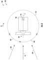
- FIG. 1 illustrates a perspective view of one embodiment of a wind turbine 100 according to the present disclosure.
- the wind turbine 100 generally includes a tower 102 extending from a support surface 104, a nacelle 106, mounted on the tower 102, and a rotor 108 coupled to the nacelle 106.
- the rotor 108 includes a rotatable hub 110 and at least one rotor blade 112 coupled to and extending outwardly from the hub 110.
- the rotor 108 includes three rotor blades 112.
- the rotor 108 may include more or less than three rotor blades 112.
- Each rotor blade 112 may be spaced about the hub 110 to facilitate rotating the rotor 108 to enable kinetic energy to be transferred from the wind into usable mechanical energy, and subsequently, electrical energy.
- the hub 110 may be rotatably coupled to an electric generator 118 ( FIG. 2 ) positioned within the nacelle 106 to permit electrical energy to be produced.
- the wind turbine 100 may also include a controller 200 configured as a turbine controller centralized within the nacelle 106.
- the controller 200 may be located within any other component of the wind turbine 100 or at a location outside the wind turbine.
- the controller 200 may be communicatively coupled to any number of the components of the wind turbine 100 in order to control the components.
- the controller 200 may include a computer or other suitable processing unit.
- the controller 200 may include suitable computer-readable instructions that, when implemented, configure the controller 200 to perform various different functions, such as receiving, transmitting and/or executing wind turbine control signals.
- the generator 118 may be coupled to the rotor 108 for producing electrical power from the rotational energy generated by the rotor 108.
- the rotor 108 may include a rotor shaft 122 coupled to the hub 110 for rotation therewith.
- the rotor shaft 122 may be rotatably supported by a main bearing 144.
- the rotor shaft 122 may, in turn, be rotatably coupled to a high-speed shaft 124 of the generator 118 through a gearbox 126 connected to a bedplate support frame 136.
- the rotor shaft 122 may provide a low-speed, high-torque input to the gearbox 126 in response to rotation of the rotor blades 112 and the hub 110.
- the gearbox 126 may then be configured to convert the low-speed, high-torque input to a high-speed, low-torque output to drive the high-speed shaft 124 and, thus, the generator 118.
- Each rotor blade 112 may also include a pitch control mechanism 120 configured to rotate each rotor blade 112 about its pitch axis 116.
- the pitch control mechanism 120 may include a pitch controller 150 configured to receive at least one pitch setpoint command from the controller 200.
- each pitch control mechanism 120 may include a pitch drive motor 128, a pitch drive gearbox 130, and a pitch drive pinion 132.
- the pitch drive motor 128 may be coupled to the pitch drive gearbox 130 so that the pitch drive motor 128 imparts mechanical force to the pitch drive gearbox 130.
- the pitch drive gearbox 130 may be coupled to the pitch drive pinion 132 for rotation therewith.
- the pitch drive pinion 132 may, in turn, be in rotational engagement with a pitch bearing 134 coupled between the hub 110 and a corresponding rotor blade 112 such that rotation of the pitch drive pinion 132 causes rotation of the pitch bearing 134.
- rotation of the pitch drive motor 128 drives the pitch drive gearbox 130 and the pitch drive pinion 132, thereby rotating the pitch bearing 134 and the rotor blade(s) 112 about the pitch axis 116.
- the wind turbine 100 may include one or more yaw drive mechanisms 138 communicatively coupled to the controller 200, with each yaw drive mechanism(s) 138 being configured to change the angle of the nacelle 106 relative to the wind (e.g., by engaging a yaw bearing 140 of the wind turbine 100).
- the controller 200 may direct the yawing of the nacelle 106 and/or the pitching of the rotor blades 112 so as to aerodynamically orient the wind turbine 100 relative to a wind(W) acting on the wind turbine 100, thereby facilitating power production.
- the wind from 152 may include a plurality of the wind turbines 100 described herein and the controller 200 configured as a farm controller.
- the wind farm 152 may include twelve wind turbines 100.
- the wind farm 152 may include any other number of wind turbines 100, such as less than twelve wind turbines 100 or greater than twelve wind turbines 100.
- the controller(s) 200 may be communicatively coupled via a wired connection, such as by connecting the controller(s) through suitable communicative links 154 (e.g., a suitable cable).
- the controller(s) may be communicatively coupled through a wireless connection, such as by using any suitable wireless communications protocol known in the art.
- the wind farm 152 may include a plurality of environmental sensors 156 for monitoring a wind profile of the wind (W) affecting the wind farm 152, and thereby the wind turbines 100.
- the environmental sensor 156 may be configured for gathering data indicative of at least one environmental condition.
- the environmental sensor 156 may be operably coupled to the controller 200.
- the environmental sensor(s) 156 may, for example, be a wind vane, an anemometer, a lidar sensor, thermometer, barometer, or other suitable sensor.
- the data gathered by the environmental sensor(s) 156 may include measures of wind direction, wind speed, wind shear, wind gust, wind veer, atmospheric pressure, pressure gradient and/or temperature.
- the environmental sensor(s) 156 may be mounted to the nacelle 106 at a location downwind of the rotor 108. It should be appreciated that the environmental sensor(s) 156 may include a network of sensors and may be positioned away from the turbine(s) 100. It should be appreciated that environmental conditions may vary significantly across a wind farm 152. Thus, the environmental sensor(s) 156 may allow for the local environmental conditions at each wind turbine 100 to be monitored individually by the respective turbine controllers and collectively by the farm controller. However, it should be appreciated that the utilization of the systems and methods disclosed herein may preclude a requirement for the environmental sensor(s) 156 to monitor certain environmental conditions, such as wind speed, in order to determine a yaw offset for the wind turbine 100
- the controller 200 may include one or more processor(s) 206 and associated memory device(s) 208 configured to perform a variety of computer-implemented functions (e.g., performing the methods, steps, calculations and the like and storing relevant data as disclosed herein). Additionally, the controller 200 may also include a communications module 210 to facilitate communications between the controller 200 and the wind turbines 100, and components thereof.
- processor(s) 206 and associated memory device(s) 208 configured to perform a variety of computer-implemented functions (e.g., performing the methods, steps, calculations and the like and storing relevant data as disclosed herein).
- the controller 200 may also include a communications module 210 to facilitate communications between the controller 200 and the wind turbines 100, and components thereof.
- the communications module 210 may include a sensor interface 212 (e.g., one or more analog-to-digital converters) to permit signals transmitted from one or more sensors, such as the environmental sensor(s) 156 to be converted into signals that can be understood and processed by the processors 206.
- the sensors may be communicatively coupled to the communications module 210 using any suitable means.
- the sensors may be coupled to the sensor interface 212 via a wired connection.
- the sensors may be coupled to the sensor interface 212 via a wireless connection, such as by using any suitable wireless communications protocol known in the art.
- the communications module 210 may also be operably coupled to an operating state control module 214 configured to change at least one wind turbine operating state.
- the term "processor” refers not only to integrated circuits referred to in the art as being included in a computer, but also refers to a controller, a microcontroller, a microcomputer, a programmable logic controller (PLC), an application specific integrated circuit, and other programmable circuits.
- the memory device(s) 208 may generally comprise memory element(s) including, but not limited to, computer readable medium (e.g., random access memory (RAM)), computer readable non-volatile medium (e.g., a flash memory), a floppy disk, a compact disc-read only memory (CD-ROM), a magneto-optical disk (MOD), a digital versatile disc (DVD) and/or other suitable memory elements.
- RAM random access memory
- CD-ROM compact disc-read only memory
- MOD magneto-optical disk
- DVD digital versatile disc
- Such memory device(s) 208 may generally be configured to store suitable computer-readable instructions that, when implemented by the processor(s) 206, configure the controller 202 to perform various functions including, but not limited to, controlling the wind turbine 100 of the plurality of wind turbines 100 of the wind farm 152 as described herein, as well as various other suitable computer-implemented functions.
- the controller 200 of the system 300 may be configured to receive a monitored performance parameter 302 and an estimated performance parameter 304 for the wind turbine 100 at multiple sampling intervals 308 of a yaw event 310. Based on the performance parameters 302, 304, the controller 200 may determine a performance differential 306 for the wind turbine 100 at the multiple sampling intervals 308. The performance differential 306 may be indicative of a ratio of, or difference, between, the monitored performance parameter 302 to the estimated performance parameter 304. For example, the controller 200 may determine the percentage of the estimated performance parameter 304 actually produced/developed by the wind turbine at the corresponding sampling interval 308.
- the performance parameter may, in an embodiment, be a performance parameter of the wind turbine 100 which is subject to monitoring.
- the performance parameter may comprise the power outputs of the wind turbines 100 of the wind farm 152.
- the performance parameter may be a tip speed ratio, a pitch setpoint, a yawing moment, and/or a bending moment. It should be appreciated that the utilization of the power production of the wind turbines 100 of the wind farm 152 may be particularly advantageous in that the measurement of the power output is employed in multiple control schemes relating to the control of the wind turbines 100 and/or the wind farm 152. Therefore, indications of the power production of the wind turbines 100 may be reliable and may be readily available to the controller 200.
- the yaw event 310 may be defined by a period between subsequent yaw setpoint commands received from the controller 200.
- yaw setpoint commands 312 may be transmitted by the controller 200 at a set interval. In an embodiment, this interval may have a duration of 60 seconds.
- the wind turbine 100 may receive the yaw setpoint command 312 and the nacelle 106 may be rotated into aerodynamic alignment with the wind (W) (e.g., aligning the axis (A) of the wind turbine 100 parallel to the wind (W)) at a first yaw angle 322.
- the rotation of the nacelle 106 may remain unchanged at the first yaw angle 322 during the yaw event 310 (e.g. 60 seconds) regardless of deviations of the wind away from aerodynamic alignment.
- the period between subsequent yaw setpoint commands 312 may include multiple sampling intervals 308.
- the controller 200 may receive indications corresponding to the performance of the wind turbine 100 in response to the environmental conditions. For example, at each sampling interval 308 of the multiple sampling intervals, the controller 200 may receive the monitored performance parameter 302, the estimated performance parameter 304, and/or a monitored wind direction 314.
- each yaw event 310 may include at least five sampling intervals 308. For example, in an embodiment each sampling interval 308 may occur once every 10 seconds over the duration of the yaw event 310. Accordingly, in such an embodiment, the controller 200 may be updated six times in between yawing events. Therefore, variations in the wind direction may be detected but not reacted to.
- the collection of the parameters at each sampling interval 308 during the corresponding yaw event 310 may serve as a test sequence for the controller 200 without necessitating a deviation from normal wind turbine 100 operations.
- the method disclosed herein may be repeated for each yaw event 310 occurring over a sampling period 316.
- the sampling period 316 may have a duration of at least one month (e.g. 30 days)).
- the sampling period 316 may be greater than five months (e.g. six months).
- the system 300 may include more than 500,000 sampling intervals 308 per wind turbine 100. It should be appreciated that the more than 500,000 sampling intervals 308 may permit the accurate detection of patterns and/or deviations from patterns which may not be accurately discernible at a lower number of sampling intervals.
- the controller 200 may determine a trendline 318 for the wind turbine 100, which correlates the performance differential 306 to a deviation of the wind direction 320 at each of the multiple sampling intervals 308.
- the deviation of the wind direction 320 may be a deviation relative to a first yaw angle 322.
- the first yaw angle 322 may correspond to a wind direction which is parallel to the axis (A) of the wind turbine 100 for the yaw event 310.
- the first yaw angle 322 may be the angle to which the nacelle is yawed in response to the yaw setpoint command 312 at the origination of the yaw event 310.
- the reciprocal of the first yaw angle may be the direction of the wind (W) at the initiation of the yaw event 310.
- the trendline 318 may, in an embodiment, be determined by the controller 200 via a polynomial expression.
- the controller 200 may, in an embodiment, utilize the trendline 318 to determine a yaw angle offset 324.
- the yaw angle offset 324 may be a difference between an angle 326 associated with the vertex 328 of the trendline 318 and the first yaw angle 322.
- the yaw angle offset 324 may be zero degrees.
- the vertex 328 may correspond to the wind direction wherein the correlation between the monitored performance parameter 302 and the estimated performance parameter 304 is maximal. Accordingly, the vertex 328 may indicate an aerodynamic alignment of the nacelle 106 to the wind (W). For example, the vertex 328 may, in an embodiment, depict the angle of the nacelle 106 relative to the wind (W) at which the wind turbine 100 is producing the full estimated performance parameter 304 (e.g., is actually producing the estimated amount of power).
- the controller 200 of the system 300 may be configured to adjust a second yaw angle 330 of the wind turbine 100 based, at least in part, on the yaw angle offset 324.
- the second yaw angle 330 may correspond to the angle to which the nacelle 106 is yawed in response to a yaw setpoint command 312 incorporating the yaw angle offset 324.
- the adjustment of the second yaw angle 330 may correspond to the introduction of a biasing value to the controller 200.
- the adjustment may correspond to an aligning or recalibration of the environmental sensor(s) 156 of the wind turbine 100.
- the adjustment may, in an embodiment, be accomplished following the installation of the wind turbine 100 or the environmental sensor 156. In an additional embodiment, the adjustment may be accomplished following a maintenance or service activity on the wind turbine 100. For example, the adjustment may include physically rotating the wind direction sensor and/or introducing a biasing factor into the control system for the wind turbine 100.
- adjusting the second yaw angle 330 of the wind turbine 100 may include establishing an alignment test interval for the wind turbine 100.
- the alignment test interval may define a test schedule for the wind turbine 100. Accordingly, the yaw angle offset may be determined in accordance with the test schedule in order to detect a drift in the alignment of the environmental sensor(s) 156 and/or the wind turbine 100.
- the controller 200 may designate a subset 332 of the plurality of wind turbines 100. The controller 200 may then receive an indication of the performance parameter 334 for each wind turbine of the designated subset 332 at each of the multiple sampling intervals 308. In at least one embodiment, the controller 200 may select the designated subset 332 of the plurality of wind turbines 100 based on a power production profile for each of the designated wind turbines 100. For example, in an embodiment, the designated subset 332 may be the wind turbine(s) 100 having a demonstrated affinity for power generation under the prevailing conditions. Alternatively, the designated subset 332 may have an average power generation capability relative to the plurality of wind turbines 100. It should be appreciated that selecting a designated subset 332 having an average, or below average power generation capability for the prevailing conditions, may ensure that a power generation level from the designated subset 332 is foreseeably achievable by other wind turbines 100 of the wind farm 152.
- the designated subset 332 may include wind turbines 100 positioned in particularly advantageous or disadvantaged locations relative to the wind (W) affecting the wind farm 152.
- the designated subset 332 may include wind turbine(s) 100 located at the point of greatest elevation of the wind farm 152 and/or along a portion of the perimeter of the wind farm 152 upwind of other wind turbines 100.
- the designated subset 332 may be in a disadvantaged position, such as in a wind shadow, or other region of disturbed wind flow. Selecting wind turbines 100 which are in a disadvantaged position may result in the designated subset 332 having a power generation capability which is foreseeably achievable by other wind turbines 100 in more advantageous positions.
- the controller 200 may model an expected performance parameter 336 for the wind turbine 100 at each of the multiple sampling intervals 308 based on the received indications of the performance parameter 334 of each wind turbine 100 of the designated subset 332.
- the expected performance parameter 336 may correspond to the estimated performance parameter 304 and may, therefore, indicate the anticipated/predicted performance parameter for the specific sampling interval 308 given the wind (W).
- the controller 200 may monitor the actual performance parameter for the wind turbine 100 at each of the multiple sampling intervals 308. It should be appreciated that the modelling may be accomplished using known techniques in the art, such as ensemble forecasting.
- the controller 200 may receive an indication of the monitored wind direction 314 from the environmental sensor 156 of the wind turbine 100 at each of the multiple sampling intervals 308 of the yaw event 310.
- the environmental sensor 156 may detect wind shifts or oscillations relative to the first yaw angle 322.
- the controller 200 may record these observations without reacting to the change in wind direction by commanding a yawing action from the yaw drive mechanism 138.
- the first yaw angle 322 may be determined by the controller 200 without a direct measurement of the wind direction. Accordingly, in an embodiment, the controller 200 may receive an indication of the yaw setpoint 312 from at least a portion of the plurality of wind turbines 100 at least once per yaw event 310. For example, in an embodiment, the controller 200 may receive an indication of the yaw direction of each wind turbine 100 of the wind farm 152 relative to a cardinal direction (N). In an embodiment, the controller 200 may determine a median yaw setpoint 338 based on the received indications of the yaw setpoints 312.
- the median yaw setpoint 338 may be indicative of a yaw-event wind direction, which may be the wind direction in axial alignment (e.g. aerodynamic alignment) with the wind turbine 100 for the yaw event 310. It should be appreciated that determining the first yaw angle 322 via the meeting yaw setpoint 338 and without a direct measurement of the wind direction may preclude errors which may be associated with the alignment/response of any individual wind turbine 100.
- the yaw-event wind direction may be considered the prevailing wind direction for the yaw event and may remain unchanged between subsequent yaw setpoint commands 312. Therefore, any wind shift away from the yaw-event wind direction may be considered to be a deviation of the wind direction 320. Accordingly, controller 200 may, at 340, determine a difference between the monitored wind direction 314 at each of the multiple sampling intervals 308 and the first yaw angle 322. The difference may correspond to the deviation of the wind direction 320 at each of the multiple sampling intervals 308 from the yaw event wind direction/first yaw angle 322.
- the controller 200 may determine a performance-parameter-correlation distribution 342 relative to the deviation of the wind direction 320 from the first yaw angle 322 for the yaw event 310.
- the performance-parameter-correlation distribution 342 may serve as a foundation for determining the trendline 318.
- the accuracy of the yaw angle offset 324 may be increased by the utilization of a second performance parameter in addition to the performance parameter 302, 304 discussed above.
- the controller may determine a second performance differential 344 for the wind turbine 100 at each of the multiple sampling intervals 308.
- the second performance differential 344 may be indicative of a ratio of a monitored second performance parameter to an estimated second performance parameter for the wind turbine 100.
- the inclusion of the second performance parameter may transform the trendline 318 into a three-dimensional trendline correlating the first performance differential 306 and the second performance differential 344 to the deviation of the wind direction 320, at each of the multiple sampling intervals 308, from the first yaw angle 322.
- the second performance parameter may include a tip speed ratio, a pitch setpoint, a yawing moment, wind speed, turbulence intensity, and/or a bending moment.
- the system 300 may define at least a first and a second yaw sector 348, 350.
- additional yaw sectors 350 may be defined as desired.
- Each of the yaw sectors 348, 350, 352 may be defined by an arc of rotation of the nacelle 106 relative to a cardinal direction (N).
- the system 300 may determine/define a first yaw angle offset 354 for the wind turbine 100 when the wind turbine 100 is in the first yaw sector 348. Additionally, the system 300 may determine/define a second yaw angle offset 356 for the wind turbine 100 when the wind turbine 100 is in the second yaw sector 350. In an embodiment, the second yaw angle offset 356 may be different than the first yaw angle offset 354. For example, the second yaw angle offset 356 may be greater than the first yaw angle offset 354 an embodiment. It should be appreciated that the utilization of multiple yaw angle offsets in distinct yaw sectors may be necessitated by the layout of the wind farm 152 (e.g.
- the utilization of multiple yaw angle offsets may permit the system 300 to tailor the adjustment of the second yaw angle 330 in consideration of topography, wake effects, and/or other site conditions.
Landscapes
- Engineering & Computer Science (AREA)
- Life Sciences & Earth Sciences (AREA)
- Sustainable Development (AREA)
- Sustainable Energy (AREA)
- Chemical & Material Sciences (AREA)
- Combustion & Propulsion (AREA)
- Mechanical Engineering (AREA)
- General Engineering & Computer Science (AREA)
- Physics & Mathematics (AREA)
- Fluid Mechanics (AREA)
- Wind Motors (AREA)
Claims (15)
- Verfahren zur Steuerung einer Windturbine eines Windparks (152) mit einer Vielzahl von Windturbinen (100), wobei das Verfahren umfasst:Bestimmen, über die Steuerung (200), eines Leistungsdifferentials (306) für die Windturbine (100) für mehrere Abtastintervalle (308) eines Gierereignisses (310), wobei das Leistungsdifferential (306) ein Verhältnis eines überwachten Leistungsparameters (302) zu einem geschätzten Leistungsparameter (304) für die Windturbine (100) anzeigt, wobei der geschätzte Leistungsparameter (304) für die Windturbine (100) auf der Grundlage von Leistungsparametern einer bestimmten Teilmenge (332) von Windturbinen des Windparks (152) bei den mehreren Abtastintervallen (308) geschätzt wird;Bestimmen, über die Steuerung (200), einer Trendlinie für die Windturbine (100), die das Leistungsdifferential (306) mit einer Abweichung einer Windrichtung (W, 314) bei jedem der mehreren Abtastintervalle (308) von einem ersten Gierwinkel (322) für das Gierereignis (310) korreliert;Bestimmen, über die Steuerung (200), eines Gierwinkel-Offsets (324), basierend auf einer Differenz zwischen einem Winkel, der einem Scheitelpunkt der Trendlinie zugeordnet ist, und dem ersten Gierwinkel (322); undEinstellen, über die Steuerung (200), eines zweiten Gierwinkels der Windturbine (100), zumindest teilweise basierend auf dem Gierwinkel-Offset (324).
- Verfahren nach Anspruch 1, wobei das Bestimmen des Leistungsdifferentials (306) für die Windturbine (100) ferner umfasst:Empfangen einer Anzeige eines überwachten Leistungsparameters (302) für jede Windturbine (100) der bestimmten Teilmenge (332) der Vielzahl von Windturbinen (100) in jedem der mehreren Abtastintervalle über die Steuerung (200); undModellieren des geschätzten Leistungsparameters für die Windturbine (100) in jedem der mehreren Abtastintervalle (308) auf der Grundlage der empfangenen Angaben des überwachten Leistungsparameters (302) jeder Windturbine (100) der bestimmten Teilmenge (332) über die Steuerung (200),.
- Verfahren nach einem der vorhergehenden Ansprüche, wobei das Bestimmen der Trendlinie für die Windturbine (100) weiterhin umfasst:Empfangen, über die Steuerung (200), einer Anzeige einer überwachten Windrichtung (314) von einem Umgebungssensor der Windturbine (100) bei jedem der mehreren Abtastintervalle (308) des Gierereignisses (310);Empfangen, über die Steuerung (200), einer Angabe eines Gier-Sollwerts (312) von mindestens einem Teil der mehreren Windturbinen (100) mindestens einmal pro Gierereignis (310);Bestimmen, über die Steuerung (200), eines mittleren Gier-Sollwerts auf der Grundlage der empfangenen Angaben, wobei der mittlere Gier-Sollwert eine Gier-Ereignis-Windrichtung anzeigt, wobei die Gier-Ereignis-Windrichtung die Windrichtung in aerodynamischer Ausrichtung mit der Windturbine (100) für das Gierereignis (310) ist und dem ersten Gierwinkel (322) entspricht;Bestimmen, über die Steuerung (200), einer Differenz zwischen der überwachten Windrichtung bei jedem der mehreren Abtastintervalle (308) und dem ersten Gierwinkel (322), wobei die Differenz der Abweichung der Windrichtung bei jedem der mehreren Abtastintervalle (308) von der Windrichtung des Gierereignisses entspricht; undBestimmen, über die Steuerung (200), einer Verteilung des Leistungsdifferentials (306) relativ zur Abweichung der Windrichtung vom ersten Gierwinkel (322) für das Gierereignis (310).
- Verfahren nach einem der vorhergehenden Ansprüche, wobei die Bestimmung des Gierwinkel-Offsets (324) weiterhin umfasst:Definieren, zumindest eines ersten Giersektors (348) und eines zweiten Giersektors (350);Bestimmen eines ersten Gierwinkel-Offsets für die Windturbine (100), wenn sich die Windturbine (100) in dem ersten Giersektor (348) befindet; undBestimmen eines zweiten Gierwinkel-Offsets (356) für die Windturbine (100), wenn sich die Windturbine (100) in dem zweiten Giersektor (350) befindet, wobei der zweite Gierwinkel-Offset (356) sich von dem ersten Gierwinkel-Offset (324) unterscheidet.
- Verfahren nach einem der vorhergehenden Ansprüche, wobei das Gierereignis (310) durch eine Periode zwischen aufeinanderfolgenden Giersollwertbefehlen definiert ist, die von der Steuerung (200) empfangen werden, wobei das Gierereignis (310) mindestens fünf Abtastintervalle umfasst.
- Verfahren nach Anspruch 5, wobei das Gierereignis (310) eine Dauer von 60 Sekunden hat und wobei jedes Abtastintervall einmal alle 10 Sekunden über die Dauer des Gierereignisses (310) auftritt.
- Verfahren nach Anspruch 5 oder 6, wobei das Verfahren für jedes Gierereignis (310) wiederholt wird, das über eine Abtastperiode von mindestens einem Monat auftritt.
- Verfahren nach einem der vorhergehenden Ansprüche, wobei Einstellen des zweiten Gierwinkels der Windturbine (100) ferner das Ausrichten oder Neukalibrieren eines Umgebungssensors der Windturbine (100) umfasst.
- Verfahren nach einem der vorhergehenden Ansprüche, wobei die Einstellung des zweiten Gierwinkels der Windturbine (100) nach der Installation der Windturbine (100) oder des Umweltsensors oder nach einer Wartungs- oder Instandhaltungsmaßnahme durchgeführt wird.
- Verfahren nach einem der vorhergehenden Ansprüche, das ferner umfasst:Festlegung eines Ausrichtungsprüfintervalls für die Windturbine (100); undBestimmen des Gierwinkel-Offsets (324) in Übereinstimmung mit einem Testplan, der durch das Ausrichtungsprüfintervall definiert ist, um eine Drift in einer Ausrichtung eines Umgebungssensors oder der Windturbine (100) zu erkennen.
- Verfahren nach einem der vorhergehenden Ansprüche, wobei der überwachte Leistungsparameter (302) eine Ausgangsleistung umfasst.
- Verfahren nach einem der vorhergehenden Ansprüche, wobei das Leistungsdifferential (306) ein erstes Leistungsdifferential (306) ist, wobei das Verfahren ferner umfasst:
Bestimmen eines zweiten Leistungsdifferentials (344) für die Windturbine (100) über die Steuerung (200) bei jedem der mehreren Abtastintervalle (308) des Gierereignisses (310), wobei das zweite Leistungsdifferential (344) ein Verhältnis eines überwachten zweiten Leistungsparameters zu einem geschätzten zweiten Leistungsparameter für die Windturbine (100) angibt, wobei die Trendlinie eine dreidimensionale Trendlinie ist, die das erste Leistungsdifferential (306) und das zweite Leistungsdifferential (344) mit der Abweichung der Windrichtung bei jedem der mehrfachen Abtastintervalle (308) von dem ersten Gierwinkel (322) korreliert. - Verfahren nach Anspruch 12, wobei die zweiten geschätzten und überwachten Leistungsparameter mindestens einen der folgenden Parameter umfassen: ein Spitzengeschwindigkeitsverhältnis, ein Drehmoment, einen Pitch-Sollwert, ein Giermoment, die Windgeschwindigkeit, die Turbulenzintensität und ein Biegemoment.
- System (300) zur Steuerung einer Windturbine (100) eines Windparks (152), wobei das System umfasst:einen Gierantriebsmechanismus zum Gieren der Windturbine (100); undeine Steuerung (200), die kommunikativ mit dem Gierantriebsmechanismus gekoppelt ist, wobei die Steuerung (200) mindestens einen Prozessor umfasst, der so konfiguriert ist, dass er eine Vielzahl von Operationen durchführt, wobei die Vielzahl von Operationen umfasst:Bestimmen eines Leistungsdifferentials (306) für die Windturbine (100) bei mehreren Abtastintervallen (308) eines Gierereignisses (310), wobei das Leistungsdifferential (306) ein Verhältnis eines überwachten Leistungsparameters (302) zu einem geschätzten Leistungsparameter (304) für die Windturbine (100) anzeigt, wobei der geschätzte Leistungsparameter (304) für die Windturbine (100) auf der Grundlage von Leistungsparametern einer bestimmten Teilmenge (332) von Windturbinen (100) des Windparks (152) bei den mehreren Abtastintervallen (308) geschätzt wird,Bestimmen einer Trendlinie für die Windturbine (100), die das Leistungsdifferential (306) mit einer Abweichung einer Windrichtung bei jedem der mehreren Abtastintervalle (308) von einem ersten Gierwinkel (322) für das Gierereignis (310) korreliert,Bestimmen eines Gierwinkel-Offsets (324) als Differenz zwischen einem mit einem Scheitelpunkt der Trendlinie verbundenen Winkel und dem ersten Gierwinkel (322); undEinstellen eines zweiten Gierwinkels der Windturbine (100), zumindest teilweise basierend auf dem Gierwinkel-Offset (324).
- System nach Anspruch 14, wobei das Bestimmen des Leistungsdifferentials (306) und der Trendlinie für die Windturbine (100) weiterhin umfasst:Empfangen einer Anzeige des überwachten Leistungsparameters (302) für jede Windturbine (100) der bestimmten Teilmenge (332) der Vielzahl von Windturbinen (100) in jedem der mehreren Abtastintervalle;Modellieren eines erwarteten Leistungsparameters für die Windturbine (100) in jedem der mehreren Abtastintervalle (308) auf der Grundlage der empfangenen Angaben des Leistungsparameters jeder Windturbine (100) der bestimmten Teilmenge;Empfangen einer Anzeige einer überwachten Windrichtung von einem Umgebungssensor der Windturbine (100) bei jedem der mehreren Abtastintervalle (308) des Gierereignisses (310);Empfangen einer Anzeige eines Gier-Sollwerts von mindestens einem Teil der Vielzahl von Windturbinen (100) mindestens einmal pro Gier-Ereignis (310);Bestimmen eines mittleren Gier-Sollwerts auf der Grundlage der empfangenen Angaben, wobei der mittlere Gier-Sollwert eine Gier-Ereignis-Windrichtung angibt, wobei die Gier-Ereignis-Windrichtung die Windrichtung in aerodynamischer Ausrichtung mit der Windturbine (100) für das Gier-Ereignis (310) ist und dem ersten Gierwinkel (322) entspricht;Bestimmen einer Differenz zwischen der überwachten Windrichtung bei jedem der mehreren Abtastintervalle (308) und dem ersten Gierwinkel (322), wobei die Differenz der Abweichung der Windrichtung bei jedem der mehreren Abtastintervalle (308) von der Windrichtung des Gierereignisses entspricht; undBestimmen einer Verteilung des Leistungsdifferentials (306) relativ zur Abweichung der Windrichtung vom ersten Gierwinkel (322) für das Gierereignis (310).
Applications Claiming Priority (1)
| Application Number | Priority Date | Filing Date | Title |
|---|---|---|---|
| US17/027,789 US11231012B1 (en) | 2020-09-22 | 2020-09-22 | Systems and methods for controlling a wind turbine |
Publications (2)
| Publication Number | Publication Date |
|---|---|
| EP3971413A1 EP3971413A1 (de) | 2022-03-23 |
| EP3971413B1 true EP3971413B1 (de) | 2024-10-30 |
Family
ID=77595456
Family Applications (1)
| Application Number | Title | Priority Date | Filing Date |
|---|---|---|---|
| EP21194388.1A Active EP3971413B1 (de) | 2020-09-22 | 2021-09-01 | Systeme und verfahren zur steuerung einer windturbine |
Country Status (5)
| Country | Link |
|---|---|
| US (1) | US11231012B1 (de) |
| EP (1) | EP3971413B1 (de) |
| CN (1) | CN114251223B (de) |
| DK (1) | DK3971413T3 (de) |
| ES (1) | ES3002312T3 (de) |
Families Citing this family (8)
| Publication number | Priority date | Publication date | Assignee | Title |
|---|---|---|---|---|
| EP3465360B1 (de) * | 2016-05-25 | 2023-02-01 | Vestas Wind Systems A/S | Windturbinensteuerungssystem mit verbesserter upsampling-technik |
| US10984154B2 (en) * | 2018-12-27 | 2021-04-20 | Utopus Insights, Inc. | System and method for evaluating models for predictive failure of renewable energy assets |
| CN113818997B (zh) * | 2020-06-19 | 2023-04-25 | 北京国电思达科技有限公司 | 一种基于大数据分析的风电机组风向自动校正方法 |
| US11649804B2 (en) * | 2021-06-07 | 2023-05-16 | General Electric Renovables Espana, S.L. | Systems and methods for controlling a wind turbine |
| CN117836514A (zh) * | 2021-08-25 | 2024-04-05 | 维斯塔斯风力系统集团公司 | 识别与风力涡轮机相关联的反复出现的自由流动风扰动 |
| CN116971917B (zh) * | 2023-06-28 | 2024-01-30 | 北京金风科创风电设备有限公司 | 偏航控制方法、装置、控制器及风力发电机组 |
| WO2025108528A1 (en) * | 2023-11-23 | 2025-05-30 | Vestas Wind Systems A/S | Calibrating a wind direction sensor of a wind turbine |
| CN118481907B (zh) * | 2024-07-01 | 2025-09-16 | 谷东科技有限公司 | 风力发电系统自适应风向追踪方法、装置、设备及介质 |
Family Cites Families (57)
| Publication number | Priority date | Publication date | Assignee | Title |
|---|---|---|---|---|
| US7004724B2 (en) | 2003-02-03 | 2006-02-28 | General Electric Company | Method and apparatus for wind turbine rotor load control based on shaft radial displacement |
| US7118339B2 (en) | 2004-06-30 | 2006-10-10 | General Electric Company | Methods and apparatus for reduction of asymmetric rotor loads in wind turbines |
| AU2007303956B2 (en) | 2006-10-02 | 2011-12-22 | Clipper Windpower, Inc. | Wind turbine with blade pitch control to compensate for wind shear and wind misalignment |
| US7883317B2 (en) | 2007-02-02 | 2011-02-08 | General Electric Company | Method for optimizing the operation of a wind turbine |
| ES2656542T3 (es) | 2007-08-31 | 2018-02-27 | Vestas Wind Systems A/S | Método para el control de al menos un mecanismo de regulación de una turbina eólica, una turbina eólica y un parque eólico |
| EP2048562B1 (de) | 2007-10-12 | 2009-08-12 | Siemens Aktiengesellschaft | Verfahren und Vorrichtung zur Bereitstellung mindestens eines Eingangssensorsignals für eine Steuerungs- und/oder Überwachungsanwendung sowie Steuerungsvorrichtung |
| EP2060785B1 (de) | 2007-11-15 | 2018-12-26 | Gamesa Innovation & Technology, S.L. | Verfahren und System für Betriebssensor |
| US8057174B2 (en) | 2008-10-09 | 2011-11-15 | General Electric Company | Method for controlling a wind turbine using a wind flow model |
| US20100092292A1 (en) | 2008-10-10 | 2010-04-15 | Jacob Johannes Nies | Apparatus and method for continuous pitching of a wind turbine |
| EP2175129A1 (de) | 2008-10-10 | 2010-04-14 | Siemens Aktiengesellschaft | Adaptive Einstellung des Blattsteigungswinkels eines Windrads |
| WO2010057737A2 (en) | 2008-11-18 | 2010-05-27 | Vestas Wind Systems A/S | A method for controlling operation of a wind turbine |
| EP2192456B1 (de) | 2008-11-26 | 2017-11-01 | Siemens Aktiengesellschaft | Schätzung der erreichbaren Stromerzeugung einer Windturbine mittels eines neuronalen Netzwerks |
| EP2213873A1 (de) | 2009-01-30 | 2010-08-04 | Siemens Aktiengesellschaft | Abschätzen einer effektiven Windrichtung für eine Windturbine mithilfe eines Lernsystems |
| GB2476316B (en) | 2009-12-21 | 2014-07-16 | Vestas Wind Sys As | A wind turbine having a control method and controller for predictive control of a wind turbine generator |
| BRPI1000003A2 (pt) * | 2010-01-27 | 2016-02-10 | Mitsubishi Heavy Ind Ltd | gerador de turbina de vento e método de controle de rotação de guinada para gerador de turbina de vento |
| US7987067B2 (en) | 2010-03-26 | 2011-07-26 | General Electric Company | Method and apparatus for optimizing wind turbine operation |
| EP2577055B8 (de) | 2010-06-02 | 2016-10-12 | Vestas Wind Systems A/S | Verfahren zum betrieb einer windturbine bei verbesserter leistungsabgabe |
| EP2444659B1 (de) | 2010-10-19 | 2016-07-06 | Siemens Aktiengesellschaft | Verfahren und System zur Einstellung eines Betriebsparameters für eine Windturbine |
| US20140003939A1 (en) * | 2011-03-15 | 2014-01-02 | Purdue Research Foundation | Load shape control of wind turbines |
| EP2518308A1 (de) | 2011-04-29 | 2012-10-31 | Siemens Aktiengesellschaft | Betriebssteuerung einer Windturbine basierend auf einem Bodenklassen-Parameterwert |
| US9606518B2 (en) | 2011-12-28 | 2017-03-28 | General Electric Company | Control system and method of predicting wind turbine power generation |
| US20130184838A1 (en) | 2012-01-06 | 2013-07-18 | Michigan Aerospace Corporation | Resource optimization using environmental and condition-based monitoring |
| EP2877742B1 (de) | 2012-07-26 | 2019-10-09 | MHI Vestas Offshore Wind A/S | Windkrachtanlagenickwinkel optimisierung und steuerung |
| US9605558B2 (en) | 2013-08-20 | 2017-03-28 | General Electric Company | System and method for preventing excessive loading on a wind turbine |
| EP2860395B1 (de) | 2013-10-09 | 2017-09-27 | Siemens Aktiengesellschaft | System zur automatischen Leistungsschätzungseinstellung |
| ES2879915T3 (es) | 2013-11-29 | 2021-11-23 | Ge Renewable Tech Wind Bv | Procedimientos para operar una turbina eólica, y turbinas eólicas |
| US9920742B2 (en) | 2014-02-20 | 2018-03-20 | General Electric Company | Dynamic cut-in wind speed for wind turbines |
| US9683552B2 (en) | 2014-03-06 | 2017-06-20 | General Electric Company | System and method for robust wind turbine operation |
| US9551322B2 (en) | 2014-04-29 | 2017-01-24 | General Electric Company | Systems and methods for optimizing operation of a wind farm |
| US9995276B2 (en) | 2014-06-19 | 2018-06-12 | Vestas Wind Systems A/S | Control of wind turbines in response to wind shear |
| US9644612B2 (en) | 2014-09-23 | 2017-05-09 | General Electric Company | Systems and methods for validating wind farm performance measurements |
| EP3224474B1 (de) | 2014-11-24 | 2020-03-25 | Vestas Wind Systems A/S | Bestimmung einer windturbinenkonfiguration |
| WO2016119795A1 (en) | 2015-01-28 | 2016-08-04 | Kk Wind Solutions A/S | Calibrating a wind vane of a wind turbine |
| US10487804B2 (en) | 2015-03-11 | 2019-11-26 | General Electric Company | Systems and methods for validating wind farm performance improvements |
| US10132295B2 (en) | 2015-05-15 | 2018-11-20 | General Electric Company | Digital system and method for managing a wind farm having plurality of wind turbines coupled to power grid |
| ES2600861B1 (es) * | 2015-07-03 | 2017-11-21 | Gamesa Innovation & Technology, S.L. | Sistema de control para detectar y evitar situaciones de desalineamiento en aerogeneradores |
| KR102362786B1 (ko) * | 2016-05-12 | 2022-02-14 | 오르스테드 윈드 파워 에이/에스 | 풍력 터빈에 대한 요 오정렬의 추정 |
| KR101789923B1 (ko) * | 2016-06-02 | 2017-10-25 | 두산중공업 주식회사 | 풍력단지 통합제어 모니터링 방법 |
| WO2017211367A1 (en) | 2016-06-07 | 2017-12-14 | Vestas Wind Systems A/S | Adaptive control of a wind turbine by detecting a change in performance |
| EP3464891B1 (de) | 2016-06-07 | 2022-01-19 | Vestas Wind Systems A/S | Adaptive steuerung einer windturbine durch erfassung einer leistungsänderung |
| US10247170B2 (en) | 2016-06-07 | 2019-04-02 | General Electric Company | System and method for controlling a dynamic system |
| ES2794827T3 (es) * | 2016-06-30 | 2020-11-19 | Vestas Wind Sys As | Método de control para una turbina eólica |
| DK179188B1 (en) * | 2016-07-06 | 2018-01-22 | Envision Energy (Jiangsu) Co Ltd | Wind turbine and a method of operating a wind turbine |
| CN106014858B (zh) * | 2016-07-21 | 2019-11-22 | 浙江运达风电股份有限公司 | 一种风电机组对风误差自动校准方法及装置 |
| US10047722B2 (en) | 2016-07-28 | 2018-08-14 | General Electric Company | System and method for controlling a wind turbine |
| EP3519693B1 (de) * | 2016-09-29 | 2020-09-16 | Vestas Wind Systems A/S | Steuerungsverfahren für eine windturbine |
| CN110168220B (zh) | 2016-12-30 | 2021-03-26 | 远景能源有限公司 | 一种评估风力涡轮机发电机性能的方法和系统 |
| US10330081B2 (en) | 2017-02-07 | 2019-06-25 | International Business Machines Corporation | Reducing curtailment of wind power generation |
| CN110537018A (zh) | 2017-04-26 | 2019-12-03 | 三菱电机株式会社 | Ai装置、激光雷达装置以及风力发电厂控制系统 |
| CN108448610B (zh) | 2018-03-12 | 2020-05-22 | 华南理工大学 | 一种基于深度学习的短期风功率预测方法 |
| CN109492777A (zh) | 2018-09-14 | 2019-03-19 | 国电电力宁夏新能源开发有限公司 | 一种基于机器学习算法平台的风电机组健康管理方法 |
| EP3791062B1 (de) * | 2018-09-17 | 2022-03-16 | American Superconductor Corporation | Gierselbstkalibrierung für einen windturbinengenerator |
| CN109667727B (zh) * | 2018-11-18 | 2020-01-10 | 浙江大学 | 一种基于功率曲线分析的风电机组偏航误差固有偏差辨识及补偿方法 |
| US10956632B2 (en) * | 2018-12-27 | 2021-03-23 | Utopus Insights, Inc. | Scalable system and engine for forecasting wind turbine failure |
| US20200210824A1 (en) * | 2018-12-28 | 2020-07-02 | Utopus Insights, Inc. | Scalable system and method for forecasting wind turbine failure with varying lead time windows |
| CN110761947B (zh) * | 2019-11-15 | 2020-09-11 | 华北电力大学 | 一种风电机组偏航校准方法及系统 |
| CN110985309B (zh) * | 2019-12-09 | 2022-03-11 | 远景智能国际私人投资有限公司 | 偏航对风异常检测方法、装置、设备和存储介质 |
-
2020
- 2020-09-22 US US17/027,789 patent/US11231012B1/en active Active
-
2021
- 2021-09-01 EP EP21194388.1A patent/EP3971413B1/de active Active
- 2021-09-01 ES ES21194388T patent/ES3002312T3/es active Active
- 2021-09-01 DK DK21194388.1T patent/DK3971413T3/da active
- 2021-09-18 CN CN202111103784.7A patent/CN114251223B/zh active Active
Also Published As
| Publication number | Publication date |
|---|---|
| ES3002312T3 (en) | 2025-03-06 |
| EP3971413A1 (de) | 2022-03-23 |
| CN114251223B (zh) | 2026-01-23 |
| US11231012B1 (en) | 2022-01-25 |
| CN114251223A (zh) | 2022-03-29 |
| DK3971413T3 (da) | 2025-02-03 |
Similar Documents
| Publication | Publication Date | Title |
|---|---|---|
| EP3971413B1 (de) | Systeme und verfahren zur steuerung einer windturbine | |
| EP2657518B1 (de) | Verfahren und Systeme zum Betrieb einer Windkraftanlage in geräuscharmer Betriebsart | |
| US7772713B2 (en) | Method and system for controlling a wind turbine | |
| EP2295793B1 (de) | System für die Bestimmung einer Ausschaltsgrenze für eine Windturbine | |
| DK1906192T3 (en) | Apparatus for evaluating sensors and / or for controlling the operation of an apparatus which includes a sensor | |
| US8035241B2 (en) | Wind turbine, control system, and method for optimizing wind turbine power production | |
| US11242841B2 (en) | System and method for controlling a wind turbine based on a collective pitch-offset | |
| EP2177755A2 (de) | Verfahren und System zum Betrieb eines Windturbinengenerators | |
| US20180283352A1 (en) | Method for Preventing Wind Turbine Rotor Blade Tower Strikes | |
| US8303251B2 (en) | Systems and methods for assembling a pitch assembly for use in a wind turbine | |
| AU2014200423A1 (en) | Method and apparatus for wind turbine noise reduction | |
| EP4265905A1 (de) | Systeme und verfahren zur steuerung einer windturbine | |
| EP4124748A1 (de) | System und verfahren zum betreiben eines windparks | |
| US20170342961A1 (en) | System and method for micrositing a wind farm for loads optimization | |
| EP2742235B1 (de) | Windkraftanlage und verfahren zur steuerung eines windturbinengenerators in der windkraftanlage | |
| EP4137695A1 (de) | System und verfahren zur steuerung einer windturbine | |
| EP3124789A1 (de) | Windturbinensteuerung mit sekundärer steuerung zur einstellung der eingangswerte der windgeschwindigkeit und/oder -richtung | |
| US20190226456A1 (en) | System and Method for Evaluating Loads of a Potential Wind Farm Site for Multiple Wind Scenarios | |
| US11421653B2 (en) | Systems and methods for multivariable control of a power generating system |
Legal Events
| Date | Code | Title | Description |
|---|---|---|---|
| PUAI | Public reference made under article 153(3) epc to a published international application that has entered the european phase |
Free format text: ORIGINAL CODE: 0009012 |
|
| STAA | Information on the status of an ep patent application or granted ep patent |
Free format text: STATUS: THE APPLICATION HAS BEEN PUBLISHED |
|
| AK | Designated contracting states |
Kind code of ref document: A1 Designated state(s): AL AT BE BG CH CY CZ DE DK EE ES FI FR GB GR HR HU IE IS IT LI LT LU LV MC MK MT NL NO PL PT RO RS SE SI SK SM TR |
|
| STAA | Information on the status of an ep patent application or granted ep patent |
Free format text: STATUS: REQUEST FOR EXAMINATION WAS MADE |
|
| 17P | Request for examination filed |
Effective date: 20220908 |
|
| RBV | Designated contracting states (corrected) |
Designated state(s): AL AT BE BG CH CY CZ DE DK EE ES FI FR GB GR HR HU IE IS IT LI LT LU LV MC MK MT NL NO PL PT RO RS SE SI SK SM TR |
|
| P01 | Opt-out of the competence of the unified patent court (upc) registered |
Effective date: 20230530 |
|
| REG | Reference to a national code |
Ipc: F03D0017000000 Ref country code: DE Ref legal event code: R079 Ref document number: 602021020911 Country of ref document: DE Free format text: PREVIOUS MAIN CLASS: F03D0007020000 Ipc: F03D0017000000 |
|
| GRAP | Despatch of communication of intention to grant a patent |
Free format text: ORIGINAL CODE: EPIDOSNIGR1 |
|
| STAA | Information on the status of an ep patent application or granted ep patent |
Free format text: STATUS: GRANT OF PATENT IS INTENDED |
|
| RIC1 | Information provided on ipc code assigned before grant |
Ipc: F03D 17/00 20160101AFI20231129BHEP |
|
| INTG | Intention to grant announced |
Effective date: 20231215 |
|
| RIN1 | Information on inventor provided before grant (corrected) |
Inventor name: WANINK, JOERG Inventor name: LANDA, BERNARD P. Inventor name: ARORA, DHIRAJ Inventor name: EVANS, SCOTT CHARLES Inventor name: SHARTZER, SAMUEL BRYAN |
|
| GRAJ | Information related to disapproval of communication of intention to grant by the applicant or resumption of examination proceedings by the epo deleted |
Free format text: ORIGINAL CODE: EPIDOSDIGR1 |
|
| STAA | Information on the status of an ep patent application or granted ep patent |
Free format text: STATUS: REQUEST FOR EXAMINATION WAS MADE |
|
| GRAP | Despatch of communication of intention to grant a patent |
Free format text: ORIGINAL CODE: EPIDOSNIGR1 |
|
| STAA | Information on the status of an ep patent application or granted ep patent |
Free format text: STATUS: GRANT OF PATENT IS INTENDED |
|
| INTC | Intention to grant announced (deleted) | ||
| INTG | Intention to grant announced |
Effective date: 20240311 |
|
| GRAJ | Information related to disapproval of communication of intention to grant by the applicant or resumption of examination proceedings by the epo deleted |
Free format text: ORIGINAL CODE: EPIDOSDIGR1 |
|
| STAA | Information on the status of an ep patent application or granted ep patent |
Free format text: STATUS: REQUEST FOR EXAMINATION WAS MADE |
|
| GRAP | Despatch of communication of intention to grant a patent |
Free format text: ORIGINAL CODE: EPIDOSNIGR1 |
|
| STAA | Information on the status of an ep patent application or granted ep patent |
Free format text: STATUS: GRANT OF PATENT IS INTENDED |
|
| INTC | Intention to grant announced (deleted) | ||
| INTG | Intention to grant announced |
Effective date: 20240516 |
|
| GRAS | Grant fee paid |
Free format text: ORIGINAL CODE: EPIDOSNIGR3 |
|
| GRAA | (expected) grant |
Free format text: ORIGINAL CODE: 0009210 |
|
| STAA | Information on the status of an ep patent application or granted ep patent |
Free format text: STATUS: THE PATENT HAS BEEN GRANTED |
|
| AK | Designated contracting states |
Kind code of ref document: B1 Designated state(s): AL AT BE BG CH CY CZ DE DK EE ES FI FR GB GR HR HU IE IS IT LI LT LU LV MC MK MT NL NO PL PT RO RS SE SI SK SM TR |
|
| REG | Reference to a national code |
Ref country code: GB Ref legal event code: FG4D |
|
| REG | Reference to a national code |
Ref country code: CH Ref legal event code: EP |
|
| REG | Reference to a national code |
Ref country code: IE Ref legal event code: FG4D |
|
| REG | Reference to a national code |
Ref country code: DE Ref legal event code: R096 Ref document number: 602021020911 Country of ref document: DE |
|
| REG | Reference to a national code |
Ref country code: DK Ref legal event code: T3 Effective date: 20250127 |
|
| REG | Reference to a national code |
Ref country code: LT Ref legal event code: MG9D |
|
| REG | Reference to a national code |
Ref country code: NL Ref legal event code: MP Effective date: 20241030 |
|
| REG | Reference to a national code |
Ref country code: ES Ref legal event code: FG2A Ref document number: 3002312 Country of ref document: ES Kind code of ref document: T3 Effective date: 20250306 |
|
| PG25 | Lapsed in a contracting state [announced via postgrant information from national office to epo] |
Ref country code: PT Free format text: LAPSE BECAUSE OF FAILURE TO SUBMIT A TRANSLATION OF THE DESCRIPTION OR TO PAY THE FEE WITHIN THE PRESCRIBED TIME-LIMIT Effective date: 20250228 Ref country code: IS Free format text: LAPSE BECAUSE OF FAILURE TO SUBMIT A TRANSLATION OF THE DESCRIPTION OR TO PAY THE FEE WITHIN THE PRESCRIBED TIME-LIMIT Effective date: 20250228 Ref country code: HR Free format text: LAPSE BECAUSE OF FAILURE TO SUBMIT A TRANSLATION OF THE DESCRIPTION OR TO PAY THE FEE WITHIN THE PRESCRIBED TIME-LIMIT Effective date: 20241030 |
|
| PG25 | Lapsed in a contracting state [announced via postgrant information from national office to epo] |
Ref country code: NL Free format text: LAPSE BECAUSE OF FAILURE TO SUBMIT A TRANSLATION OF THE DESCRIPTION OR TO PAY THE FEE WITHIN THE PRESCRIBED TIME-LIMIT Effective date: 20241030 Ref country code: FI Free format text: LAPSE BECAUSE OF FAILURE TO SUBMIT A TRANSLATION OF THE DESCRIPTION OR TO PAY THE FEE WITHIN THE PRESCRIBED TIME-LIMIT Effective date: 20241030 |
|
| REG | Reference to a national code |
Ref country code: AT Ref legal event code: MK05 Ref document number: 1737090 Country of ref document: AT Kind code of ref document: T Effective date: 20241030 |
|
| PG25 | Lapsed in a contracting state [announced via postgrant information from national office to epo] |
Ref country code: BG Free format text: LAPSE BECAUSE OF FAILURE TO SUBMIT A TRANSLATION OF THE DESCRIPTION OR TO PAY THE FEE WITHIN THE PRESCRIBED TIME-LIMIT Effective date: 20241030 |
|
| PG25 | Lapsed in a contracting state [announced via postgrant information from national office to epo] |
Ref country code: NO Free format text: LAPSE BECAUSE OF FAILURE TO SUBMIT A TRANSLATION OF THE DESCRIPTION OR TO PAY THE FEE WITHIN THE PRESCRIBED TIME-LIMIT Effective date: 20250130 |
|
| PG25 | Lapsed in a contracting state [announced via postgrant information from national office to epo] |
Ref country code: AT Free format text: LAPSE BECAUSE OF FAILURE TO SUBMIT A TRANSLATION OF THE DESCRIPTION OR TO PAY THE FEE WITHIN THE PRESCRIBED TIME-LIMIT Effective date: 20241030 Ref country code: GR Free format text: LAPSE BECAUSE OF FAILURE TO SUBMIT A TRANSLATION OF THE DESCRIPTION OR TO PAY THE FEE WITHIN THE PRESCRIBED TIME-LIMIT Effective date: 20250131 Ref country code: LV Free format text: LAPSE BECAUSE OF FAILURE TO SUBMIT A TRANSLATION OF THE DESCRIPTION OR TO PAY THE FEE WITHIN THE PRESCRIBED TIME-LIMIT Effective date: 20241030 |
|
| PG25 | Lapsed in a contracting state [announced via postgrant information from national office to epo] |
Ref country code: PL Free format text: LAPSE BECAUSE OF FAILURE TO SUBMIT A TRANSLATION OF THE DESCRIPTION OR TO PAY THE FEE WITHIN THE PRESCRIBED TIME-LIMIT Effective date: 20241030 |
|
| PG25 | Lapsed in a contracting state [announced via postgrant information from national office to epo] |
Ref country code: RS Free format text: LAPSE BECAUSE OF FAILURE TO SUBMIT A TRANSLATION OF THE DESCRIPTION OR TO PAY THE FEE WITHIN THE PRESCRIBED TIME-LIMIT Effective date: 20250130 |
|
| PG25 | Lapsed in a contracting state [announced via postgrant information from national office to epo] |
Ref country code: SM Free format text: LAPSE BECAUSE OF FAILURE TO SUBMIT A TRANSLATION OF THE DESCRIPTION OR TO PAY THE FEE WITHIN THE PRESCRIBED TIME-LIMIT Effective date: 20241030 |
|
| PG25 | Lapsed in a contracting state [announced via postgrant information from national office to epo] |
Ref country code: EE Free format text: LAPSE BECAUSE OF FAILURE TO SUBMIT A TRANSLATION OF THE DESCRIPTION OR TO PAY THE FEE WITHIN THE PRESCRIBED TIME-LIMIT Effective date: 20241030 |
|
| PG25 | Lapsed in a contracting state [announced via postgrant information from national office to epo] |
Ref country code: RO Free format text: LAPSE BECAUSE OF FAILURE TO SUBMIT A TRANSLATION OF THE DESCRIPTION OR TO PAY THE FEE WITHIN THE PRESCRIBED TIME-LIMIT Effective date: 20241030 |
|
| PG25 | Lapsed in a contracting state [announced via postgrant information from national office to epo] |
Ref country code: SK Free format text: LAPSE BECAUSE OF FAILURE TO SUBMIT A TRANSLATION OF THE DESCRIPTION OR TO PAY THE FEE WITHIN THE PRESCRIBED TIME-LIMIT Effective date: 20241030 |
|
| PG25 | Lapsed in a contracting state [announced via postgrant information from national office to epo] |
Ref country code: CZ Free format text: LAPSE BECAUSE OF FAILURE TO SUBMIT A TRANSLATION OF THE DESCRIPTION OR TO PAY THE FEE WITHIN THE PRESCRIBED TIME-LIMIT Effective date: 20241030 |
|
| PG25 | Lapsed in a contracting state [announced via postgrant information from national office to epo] |
Ref country code: IT Free format text: LAPSE BECAUSE OF FAILURE TO SUBMIT A TRANSLATION OF THE DESCRIPTION OR TO PAY THE FEE WITHIN THE PRESCRIBED TIME-LIMIT Effective date: 20241030 |
|
| REG | Reference to a national code |
Ref country code: DE Ref legal event code: R097 Ref document number: 602021020911 Country of ref document: DE |
|
| PLBE | No opposition filed within time limit |
Free format text: ORIGINAL CODE: 0009261 |
|
| STAA | Information on the status of an ep patent application or granted ep patent |
Free format text: STATUS: NO OPPOSITION FILED WITHIN TIME LIMIT |
|
| PG25 | Lapsed in a contracting state [announced via postgrant information from national office to epo] |
Ref country code: SE Free format text: LAPSE BECAUSE OF FAILURE TO SUBMIT A TRANSLATION OF THE DESCRIPTION OR TO PAY THE FEE WITHIN THE PRESCRIBED TIME-LIMIT Effective date: 20241030 |
|
| 26N | No opposition filed |
Effective date: 20250731 |
|
| PGFP | Annual fee paid to national office [announced via postgrant information from national office to epo] |
Ref country code: DK Payment date: 20250820 Year of fee payment: 5 Ref country code: DE Payment date: 20250820 Year of fee payment: 5 |
|
| PGFP | Annual fee paid to national office [announced via postgrant information from national office to epo] |
Ref country code: ES Payment date: 20251001 Year of fee payment: 5 |