EP3971160A1 - Method for producing metal-organic structure - Google Patents
Method for producing metal-organic structure Download PDFInfo
- Publication number
- EP3971160A1 EP3971160A1 EP20806271.1A EP20806271A EP3971160A1 EP 3971160 A1 EP3971160 A1 EP 3971160A1 EP 20806271 A EP20806271 A EP 20806271A EP 3971160 A1 EP3971160 A1 EP 3971160A1
- Authority
- EP
- European Patent Office
- Prior art keywords
- formulation
- solvent
- metal
- reaction vessel
- metal ion
- Prior art date
- Legal status (The legal status is an assumption and is not a legal conclusion. Google has not performed a legal analysis and makes no representation as to the accuracy of the status listed.)
- Pending
Links
- 238000004519 manufacturing process Methods 0.000 title claims abstract description 31
- 239000000203 mixture Substances 0.000 claims abstract description 58
- 238000009472 formulation Methods 0.000 claims abstract description 55
- 239000012621 metal-organic framework Substances 0.000 claims abstract description 55
- 239000002904 solvent Substances 0.000 claims abstract description 32
- 229910021645 metal ion Inorganic materials 0.000 claims abstract description 27
- 239000003446 ligand Substances 0.000 claims abstract description 23
- 238000006243 chemical reaction Methods 0.000 claims description 49
- 238000000034 method Methods 0.000 claims description 38
- IJGRMHOSHXDMSA-UHFFFAOYSA-N Atomic nitrogen Chemical compound N#N IJGRMHOSHXDMSA-UHFFFAOYSA-N 0.000 claims description 9
- XKRFYHLGVUSROY-UHFFFAOYSA-N Argon Chemical compound [Ar] XKRFYHLGVUSROY-UHFFFAOYSA-N 0.000 claims description 8
- 239000007789 gas Substances 0.000 claims description 7
- 238000003756 stirring Methods 0.000 claims description 7
- QVGXLLKOCUKJST-UHFFFAOYSA-N atomic oxygen Chemical compound [O] QVGXLLKOCUKJST-UHFFFAOYSA-N 0.000 claims description 6
- 229910052760 oxygen Inorganic materials 0.000 claims description 6
- 239000001301 oxygen Substances 0.000 claims description 6
- 239000002245 particle Substances 0.000 claims description 6
- 239000013259 porous coordination polymer Substances 0.000 claims description 6
- 239000003570 air Substances 0.000 claims description 5
- 229910052757 nitrogen Inorganic materials 0.000 claims description 5
- 239000010409 thin film Substances 0.000 claims description 5
- 229910052786 argon Inorganic materials 0.000 claims description 4
- 238000009835 boiling Methods 0.000 claims description 4
- LFQSCWFLJHTTHZ-UHFFFAOYSA-N Ethanol Chemical compound CCO LFQSCWFLJHTTHZ-UHFFFAOYSA-N 0.000 description 11
- 239000000126 substance Substances 0.000 description 11
- 229910052751 metal Inorganic materials 0.000 description 9
- -1 carboxylic acid anions Chemical class 0.000 description 8
- 230000015572 biosynthetic process Effects 0.000 description 7
- 238000003786 synthesis reaction Methods 0.000 description 7
- QTBSBXVTEAMEQO-UHFFFAOYSA-N Acetic acid Chemical compound CC(O)=O QTBSBXVTEAMEQO-UHFFFAOYSA-N 0.000 description 6
- OKKJLVBELUTLKV-UHFFFAOYSA-N Methanol Chemical compound OC OKKJLVBELUTLKV-UHFFFAOYSA-N 0.000 description 6
- RAXXELZNTBOGNW-UHFFFAOYSA-N imidazole Natural products C1=CNC=N1 RAXXELZNTBOGNW-UHFFFAOYSA-N 0.000 description 6
- 239000007795 chemical reaction product Substances 0.000 description 5
- 239000002184 metal Substances 0.000 description 5
- ZMXDDKWLCZADIW-UHFFFAOYSA-N N,N-Dimethylformamide Chemical compound CN(C)C=O ZMXDDKWLCZADIW-UHFFFAOYSA-N 0.000 description 4
- KKEYFWRCBNTPAC-UHFFFAOYSA-N Terephthalic acid Chemical compound OC(=O)C1=CC=C(C(O)=O)C=C1 KKEYFWRCBNTPAC-UHFFFAOYSA-N 0.000 description 4
- 239000012298 atmosphere Substances 0.000 description 4
- 238000002347 injection Methods 0.000 description 4
- 239000007924 injection Substances 0.000 description 4
- QQVIHTHCMHWDBS-UHFFFAOYSA-N isophthalic acid Chemical compound OC(=O)C1=CC=CC(C(O)=O)=C1 QQVIHTHCMHWDBS-UHFFFAOYSA-N 0.000 description 4
- VNWKTOKETHGBQD-UHFFFAOYSA-N methane Chemical compound C VNWKTOKETHGBQD-UHFFFAOYSA-N 0.000 description 4
- BDAGIHXWWSANSR-UHFFFAOYSA-N methanoic acid Natural products OC=O BDAGIHXWWSANSR-UHFFFAOYSA-N 0.000 description 4
- OISVCGZHLKNMSJ-UHFFFAOYSA-N 2,6-dimethylpyridine Chemical compound CC1=CC=CC(C)=N1 OISVCGZHLKNMSJ-UHFFFAOYSA-N 0.000 description 3
- XEKOWRVHYACXOJ-UHFFFAOYSA-N Ethyl acetate Chemical compound CCOC(C)=O XEKOWRVHYACXOJ-UHFFFAOYSA-N 0.000 description 3
- VZCYOOQTPOCHFL-OWOJBTEDSA-N Fumaric acid Chemical compound OC(=O)\C=C\C(O)=O VZCYOOQTPOCHFL-OWOJBTEDSA-N 0.000 description 3
- KWYUFKZDYYNOTN-UHFFFAOYSA-M Potassium hydroxide Chemical compound [OH-].[K+] KWYUFKZDYYNOTN-UHFFFAOYSA-M 0.000 description 3
- HEMHJVSKTPXQMS-UHFFFAOYSA-M Sodium hydroxide Chemical compound [OH-].[Na+] HEMHJVSKTPXQMS-UHFFFAOYSA-M 0.000 description 3
- ZMANZCXQSJIPKH-UHFFFAOYSA-N Triethylamine Chemical compound CCN(CC)CC ZMANZCXQSJIPKH-UHFFFAOYSA-N 0.000 description 3
- KRKNYBCHXYNGOX-UHFFFAOYSA-N citric acid Chemical compound OC(=O)CC(O)(C(O)=O)CC(O)=O KRKNYBCHXYNGOX-UHFFFAOYSA-N 0.000 description 3
- 230000000052 comparative effect Effects 0.000 description 3
- 238000004898 kneading Methods 0.000 description 3
- 239000000463 material Substances 0.000 description 3
- 239000002994 raw material Substances 0.000 description 3
- 239000000376 reactant Substances 0.000 description 3
- 230000035484 reaction time Effects 0.000 description 3
- 238000010008 shearing Methods 0.000 description 3
- 239000000243 solution Substances 0.000 description 3
- 238000004729 solvothermal method Methods 0.000 description 3
- 238000003860 storage Methods 0.000 description 3
- 230000002194 synthesizing effect Effects 0.000 description 3
- OSWFIVFLDKOXQC-UHFFFAOYSA-N 4-(3-methoxyphenyl)aniline Chemical compound COC1=CC=CC(C=2C=CC(N)=CC=2)=C1 OSWFIVFLDKOXQC-UHFFFAOYSA-N 0.000 description 2
- VEXZGXHMUGYJMC-UHFFFAOYSA-N Hydrochloric acid Chemical compound Cl VEXZGXHMUGYJMC-UHFFFAOYSA-N 0.000 description 2
- XEEYBQQBJWHFJM-UHFFFAOYSA-N Iron Chemical compound [Fe] XEEYBQQBJWHFJM-UHFFFAOYSA-N 0.000 description 2
- SUAKHGWARZSWIH-UHFFFAOYSA-N N,N‐diethylformamide Chemical compound CCN(CC)C=O SUAKHGWARZSWIH-UHFFFAOYSA-N 0.000 description 2
- PXHVJJICTQNCMI-UHFFFAOYSA-N Nickel Chemical compound [Ni] PXHVJJICTQNCMI-UHFFFAOYSA-N 0.000 description 2
- NBIIXXVUZAFLBC-UHFFFAOYSA-N Phosphoric acid Chemical compound OP(O)(O)=O NBIIXXVUZAFLBC-UHFFFAOYSA-N 0.000 description 2
- JUJWROOIHBZHMG-UHFFFAOYSA-N Pyridine Chemical compound C1=CC=NC=C1 JUJWROOIHBZHMG-UHFFFAOYSA-N 0.000 description 2
- QAOWNCQODCNURD-UHFFFAOYSA-N Sulfuric acid Chemical compound OS(O)(=O)=O QAOWNCQODCNURD-UHFFFAOYSA-N 0.000 description 2
- DTQVDTLACAAQTR-UHFFFAOYSA-N Trifluoroacetic acid Chemical compound OC(=O)C(F)(F)F DTQVDTLACAAQTR-UHFFFAOYSA-N 0.000 description 2
- 230000002378 acidificating effect Effects 0.000 description 2
- QMKYBPDZANOJGF-UHFFFAOYSA-N benzene-1,3,5-tricarboxylic acid Chemical compound OC(=O)C1=CC(C(O)=O)=CC(C(O)=O)=C1 QMKYBPDZANOJGF-UHFFFAOYSA-N 0.000 description 2
- 150000001875 compounds Chemical class 0.000 description 2
- 235000019253 formic acid Nutrition 0.000 description 2
- 230000005484 gravity Effects 0.000 description 2
- 150000002391 heterocyclic compounds Chemical class 0.000 description 2
- 238000005259 measurement Methods 0.000 description 2
- 239000012299 nitrogen atmosphere Substances 0.000 description 2
- 239000013110 organic ligand Substances 0.000 description 2
- 150000003839 salts Chemical class 0.000 description 2
- 239000007787 solid Substances 0.000 description 2
- 238000010532 solid phase synthesis reaction Methods 0.000 description 2
- 238000001179 sorption measurement Methods 0.000 description 2
- 229910001220 stainless steel Inorganic materials 0.000 description 2
- 239000010935 stainless steel Substances 0.000 description 2
- 238000001308 synthesis method Methods 0.000 description 2
- VZCYOOQTPOCHFL-UHFFFAOYSA-N trans-butenedioic acid Natural products OC(=O)C=CC(O)=O VZCYOOQTPOCHFL-UHFFFAOYSA-N 0.000 description 2
- XLYOFNOQVPJJNP-UHFFFAOYSA-N water Substances O XLYOFNOQVPJJNP-UHFFFAOYSA-N 0.000 description 2
- BJEPYKJPYRNKOW-REOHCLBHSA-N (S)-malic acid Chemical compound OC(=O)[C@@H](O)CC(O)=O BJEPYKJPYRNKOW-REOHCLBHSA-N 0.000 description 1
- OHLSHRJUBRUKAN-UHFFFAOYSA-N 2,3-dihydroxyterephthalic acid Chemical compound OC(=O)C1=CC=C(C(O)=O)C(O)=C1O OHLSHRJUBRUKAN-UHFFFAOYSA-N 0.000 description 1
- BZFGKBQHQJVAHS-UHFFFAOYSA-N 2-(trifluoromethyl)pyridine-4-carboxylic acid Chemical compound OC(=O)C1=CC=NC(C(F)(F)F)=C1 BZFGKBQHQJVAHS-UHFFFAOYSA-N 0.000 description 1
- LXBGSDVWAMZHDD-UHFFFAOYSA-N 2-methyl-1h-imidazole Chemical compound CC1=NC=CN1 LXBGSDVWAMZHDD-UHFFFAOYSA-N 0.000 description 1
- XWKFPIODWVPXLX-UHFFFAOYSA-N 2-methyl-5-methylpyridine Natural products CC1=CC=C(C)N=C1 XWKFPIODWVPXLX-UHFFFAOYSA-N 0.000 description 1
- GFFGJBXGBJISGV-UHFFFAOYSA-N Adenine Chemical compound NC1=NC=NC2=C1N=CN2 GFFGJBXGBJISGV-UHFFFAOYSA-N 0.000 description 1
- 229930024421 Adenine Natural products 0.000 description 1
- ROFVEXUMMXZLPA-UHFFFAOYSA-N Bipyridyl Chemical compound N1=CC=CC=C1C1=CC=CC=N1 ROFVEXUMMXZLPA-UHFFFAOYSA-N 0.000 description 1
- OYPRJOBELJOOCE-UHFFFAOYSA-N Calcium Chemical compound [Ca] OYPRJOBELJOOCE-UHFFFAOYSA-N 0.000 description 1
- VYZAMTAEIAYCRO-UHFFFAOYSA-N Chromium Chemical compound [Cr] VYZAMTAEIAYCRO-UHFFFAOYSA-N 0.000 description 1
- RYGMFSIKBFXOCR-UHFFFAOYSA-N Copper Chemical compound [Cu] RYGMFSIKBFXOCR-UHFFFAOYSA-N 0.000 description 1
- FYYHWMGAXLPEAU-UHFFFAOYSA-N Magnesium Chemical compound [Mg] FYYHWMGAXLPEAU-UHFFFAOYSA-N 0.000 description 1
- GRYLNZFGIOXLOG-UHFFFAOYSA-N Nitric acid Chemical compound O[N+]([O-])=O GRYLNZFGIOXLOG-UHFFFAOYSA-N 0.000 description 1
- 229910019142 PO4 Inorganic materials 0.000 description 1
- 239000004698 Polyethylene Substances 0.000 description 1
- HCHKCACWOHOZIP-UHFFFAOYSA-N Zinc Chemical compound [Zn] HCHKCACWOHOZIP-UHFFFAOYSA-N 0.000 description 1
- QCWXUUIWCKQGHC-UHFFFAOYSA-N Zirconium Chemical compound [Zr] QCWXUUIWCKQGHC-UHFFFAOYSA-N 0.000 description 1
- 150000001242 acetic acid derivatives Chemical class 0.000 description 1
- 229960000643 adenine Drugs 0.000 description 1
- 150000001298 alcohols Chemical class 0.000 description 1
- 229910052783 alkali metal Inorganic materials 0.000 description 1
- 150000001340 alkali metals Chemical class 0.000 description 1
- 229910052784 alkaline earth metal Inorganic materials 0.000 description 1
- 150000001342 alkaline earth metals Chemical class 0.000 description 1
- BJEPYKJPYRNKOW-UHFFFAOYSA-N alpha-hydroxysuccinic acid Natural products OC(=O)C(O)CC(O)=O BJEPYKJPYRNKOW-UHFFFAOYSA-N 0.000 description 1
- 229910052782 aluminium Inorganic materials 0.000 description 1
- XAGFODPZIPBFFR-UHFFFAOYSA-N aluminium Chemical compound [Al] XAGFODPZIPBFFR-UHFFFAOYSA-N 0.000 description 1
- 229910000147 aluminium phosphate Inorganic materials 0.000 description 1
- 150000001408 amides Chemical class 0.000 description 1
- 150000001450 anions Chemical class 0.000 description 1
- 239000012300 argon atmosphere Substances 0.000 description 1
- 238000000498 ball milling Methods 0.000 description 1
- ZOQOMVWXXWHKGT-UHFFFAOYSA-N benzene-1,3,5-tricarboxylic acid Chemical compound OC(=O)C1=CC(C(O)=O)=CC(C(O)=O)=C1.OC(=O)C1=CC(C(O)=O)=CC(C(O)=O)=C1 ZOQOMVWXXWHKGT-UHFFFAOYSA-N 0.000 description 1
- YTIVTFGABIZHHX-UHFFFAOYSA-N butynedioic acid Chemical compound OC(=O)C#CC(O)=O YTIVTFGABIZHHX-UHFFFAOYSA-N 0.000 description 1
- 229910052791 calcium Inorganic materials 0.000 description 1
- 239000011575 calcium Substances 0.000 description 1
- 150000004649 carbonic acid derivatives Chemical class 0.000 description 1
- 150000001735 carboxylic acids Chemical class 0.000 description 1
- 239000003795 chemical substances by application Substances 0.000 description 1
- 150000001805 chlorine compounds Chemical class 0.000 description 1
- 229910052804 chromium Inorganic materials 0.000 description 1
- 239000011651 chromium Substances 0.000 description 1
- 229910017052 cobalt Inorganic materials 0.000 description 1
- 239000010941 cobalt Substances 0.000 description 1
- GUTLYIVDDKVIGB-UHFFFAOYSA-N cobalt atom Chemical compound [Co] GUTLYIVDDKVIGB-UHFFFAOYSA-N 0.000 description 1
- 229910052802 copper Inorganic materials 0.000 description 1
- 239000010949 copper Substances 0.000 description 1
- HPNMFZURTQLUMO-UHFFFAOYSA-N diethylamine Chemical compound CCNCC HPNMFZURTQLUMO-UHFFFAOYSA-N 0.000 description 1
- 230000000694 effects Effects 0.000 description 1
- 150000002148 esters Chemical class 0.000 description 1
- 238000011156 evaluation Methods 0.000 description 1
- 230000001747 exhibiting effect Effects 0.000 description 1
- 239000001530 fumaric acid Substances 0.000 description 1
- 238000009775 high-speed stirring Methods 0.000 description 1
- 238000001027 hydrothermal synthesis Methods 0.000 description 1
- 150000004679 hydroxides Chemical class 0.000 description 1
- 239000011261 inert gas Substances 0.000 description 1
- 229910017053 inorganic salt Inorganic materials 0.000 description 1
- 229910052742 iron Inorganic materials 0.000 description 1
- TWBYWOBDOCUKOW-UHFFFAOYSA-N isonicotinic acid Natural products OC(=O)C1=CC=NC=C1 TWBYWOBDOCUKOW-UHFFFAOYSA-N 0.000 description 1
- 239000007788 liquid Substances 0.000 description 1
- 239000007791 liquid phase Substances 0.000 description 1
- 229910052749 magnesium Inorganic materials 0.000 description 1
- 239000011777 magnesium Substances 0.000 description 1
- 239000001630 malic acid Substances 0.000 description 1
- 235000011090 malic acid Nutrition 0.000 description 1
- 239000004570 mortar (masonry) Substances 0.000 description 1
- 239000003345 natural gas Substances 0.000 description 1
- 229910052759 nickel Inorganic materials 0.000 description 1
- 150000002823 nitrates Chemical class 0.000 description 1
- 229910017604 nitric acid Inorganic materials 0.000 description 1
- 150000002902 organometallic compounds Chemical class 0.000 description 1
- 239000010452 phosphate Substances 0.000 description 1
- 229920000573 polyethylene Polymers 0.000 description 1
- 230000002035 prolonged effect Effects 0.000 description 1
- UMJSCPRVCHMLSP-UHFFFAOYSA-N pyridine Natural products COC1=CC=CN=C1 UMJSCPRVCHMLSP-UHFFFAOYSA-N 0.000 description 1
- 238000000926 separation method Methods 0.000 description 1
- 238000004904 shortening Methods 0.000 description 1
- 239000002002 slurry Substances 0.000 description 1
- 150000003467 sulfuric acid derivatives Chemical class 0.000 description 1
- 230000002459 sustained effect Effects 0.000 description 1
- 229910052723 transition metal Inorganic materials 0.000 description 1
- 150000003624 transition metals Chemical class 0.000 description 1
- MDGRUBNBPOYDKU-UHFFFAOYSA-K trisodium benzene-1,3,5-tricarboxylate Chemical compound [Na+].[Na+].[Na+].[O-]C(=O)C1=CC(C([O-])=O)=CC(C([O-])=O)=C1 MDGRUBNBPOYDKU-UHFFFAOYSA-K 0.000 description 1
- 229910052725 zinc Inorganic materials 0.000 description 1
- 239000011701 zinc Substances 0.000 description 1
- 229910052726 zirconium Inorganic materials 0.000 description 1
Images

Classifications
-
- C—CHEMISTRY; METALLURGY
- C07—ORGANIC CHEMISTRY
- C07F—ACYCLIC, CARBOCYCLIC OR HETEROCYCLIC COMPOUNDS CONTAINING ELEMENTS OTHER THAN CARBON, HYDROGEN, HALOGEN, OXYGEN, NITROGEN, SULFUR, SELENIUM OR TELLURIUM
- C07F3/00—Compounds containing elements of Groups 2 or 12 of the Periodic Table
- C07F3/06—Zinc compounds
-
- C—CHEMISTRY; METALLURGY
- C07—ORGANIC CHEMISTRY
- C07C—ACYCLIC OR CARBOCYCLIC COMPOUNDS
- C07C51/00—Preparation of carboxylic acids or their salts, halides or anhydrides
- C07C51/41—Preparation of salts of carboxylic acids
- C07C51/412—Preparation of salts of carboxylic acids by conversion of the acids, their salts, esters or anhydrides with the same carboxylic acid part
-
- C—CHEMISTRY; METALLURGY
- C07—ORGANIC CHEMISTRY
- C07F—ACYCLIC, CARBOCYCLIC OR HETEROCYCLIC COMPOUNDS CONTAINING ELEMENTS OTHER THAN CARBON, HYDROGEN, HALOGEN, OXYGEN, NITROGEN, SULFUR, SELENIUM OR TELLURIUM
- C07F1/00—Compounds containing elements of Groups 1 or 11 of the Periodic Table
- C07F1/08—Copper compounds
-
- C—CHEMISTRY; METALLURGY
- C07—ORGANIC CHEMISTRY
- C07F—ACYCLIC, CARBOCYCLIC OR HETEROCYCLIC COMPOUNDS CONTAINING ELEMENTS OTHER THAN CARBON, HYDROGEN, HALOGEN, OXYGEN, NITROGEN, SULFUR, SELENIUM OR TELLURIUM
- C07F11/00—Compounds containing elements of Groups 6 or 16 of the Periodic Table
-
- C—CHEMISTRY; METALLURGY
- C07—ORGANIC CHEMISTRY
- C07F—ACYCLIC, CARBOCYCLIC OR HETEROCYCLIC COMPOUNDS CONTAINING ELEMENTS OTHER THAN CARBON, HYDROGEN, HALOGEN, OXYGEN, NITROGEN, SULFUR, SELENIUM OR TELLURIUM
- C07F11/00—Compounds containing elements of Groups 6 or 16 of the Periodic Table
- C07F11/005—Compounds containing elements of Groups 6 or 16 of the Periodic Table compounds without a metal-carbon linkage
-
- C—CHEMISTRY; METALLURGY
- C07—ORGANIC CHEMISTRY
- C07F—ACYCLIC, CARBOCYCLIC OR HETEROCYCLIC COMPOUNDS CONTAINING ELEMENTS OTHER THAN CARBON, HYDROGEN, HALOGEN, OXYGEN, NITROGEN, SULFUR, SELENIUM OR TELLURIUM
- C07F15/00—Compounds containing elements of Groups 8, 9, 10 or 18 of the Periodic Table
- C07F15/02—Iron compounds
-
- C—CHEMISTRY; METALLURGY
- C07—ORGANIC CHEMISTRY
- C07F—ACYCLIC, CARBOCYCLIC OR HETEROCYCLIC COMPOUNDS CONTAINING ELEMENTS OTHER THAN CARBON, HYDROGEN, HALOGEN, OXYGEN, NITROGEN, SULFUR, SELENIUM OR TELLURIUM
- C07F15/00—Compounds containing elements of Groups 8, 9, 10 or 18 of the Periodic Table
- C07F15/02—Iron compounds
- C07F15/025—Iron compounds without a metal-carbon linkage
-
- C—CHEMISTRY; METALLURGY
- C07—ORGANIC CHEMISTRY
- C07F—ACYCLIC, CARBOCYCLIC OR HETEROCYCLIC COMPOUNDS CONTAINING ELEMENTS OTHER THAN CARBON, HYDROGEN, HALOGEN, OXYGEN, NITROGEN, SULFUR, SELENIUM OR TELLURIUM
- C07F3/00—Compounds containing elements of Groups 2 or 12 of the Periodic Table
- C07F3/003—Compounds containing elements of Groups 2 or 12 of the Periodic Table without C-Metal linkages
-
- C—CHEMISTRY; METALLURGY
- C07—ORGANIC CHEMISTRY
- C07F—ACYCLIC, CARBOCYCLIC OR HETEROCYCLIC COMPOUNDS CONTAINING ELEMENTS OTHER THAN CARBON, HYDROGEN, HALOGEN, OXYGEN, NITROGEN, SULFUR, SELENIUM OR TELLURIUM
- C07F3/00—Compounds containing elements of Groups 2 or 12 of the Periodic Table
- C07F3/02—Magnesium compounds
-
- C—CHEMISTRY; METALLURGY
- C07—ORGANIC CHEMISTRY
- C07F—ACYCLIC, CARBOCYCLIC OR HETEROCYCLIC COMPOUNDS CONTAINING ELEMENTS OTHER THAN CARBON, HYDROGEN, HALOGEN, OXYGEN, NITROGEN, SULFUR, SELENIUM OR TELLURIUM
- C07F3/00—Compounds containing elements of Groups 2 or 12 of the Periodic Table
- C07F3/04—Calcium compounds
-
- C—CHEMISTRY; METALLURGY
- C07—ORGANIC CHEMISTRY
- C07F—ACYCLIC, CARBOCYCLIC OR HETEROCYCLIC COMPOUNDS CONTAINING ELEMENTS OTHER THAN CARBON, HYDROGEN, HALOGEN, OXYGEN, NITROGEN, SULFUR, SELENIUM OR TELLURIUM
- C07F5/00—Compounds containing elements of Groups 3 or 13 of the Periodic Table
- C07F5/06—Aluminium compounds
-
- C—CHEMISTRY; METALLURGY
- C07—ORGANIC CHEMISTRY
- C07F—ACYCLIC, CARBOCYCLIC OR HETEROCYCLIC COMPOUNDS CONTAINING ELEMENTS OTHER THAN CARBON, HYDROGEN, HALOGEN, OXYGEN, NITROGEN, SULFUR, SELENIUM OR TELLURIUM
- C07F5/00—Compounds containing elements of Groups 3 or 13 of the Periodic Table
- C07F5/06—Aluminium compounds
- C07F5/069—Aluminium compounds without C-aluminium linkages
-
- C—CHEMISTRY; METALLURGY
- C07—ORGANIC CHEMISTRY
- C07F—ACYCLIC, CARBOCYCLIC OR HETEROCYCLIC COMPOUNDS CONTAINING ELEMENTS OTHER THAN CARBON, HYDROGEN, HALOGEN, OXYGEN, NITROGEN, SULFUR, SELENIUM OR TELLURIUM
- C07F7/00—Compounds containing elements of Groups 4 or 14 of the Periodic Table
Definitions
- the present disclosure relates to a method for producing Metal-Organic Frameworks (MOFs).
- MOFs Metal-Organic Frameworks
- Metal-Organic Framework is a compound having a structure in which metal atoms are crosslinked with each other by an organic ligand, and typically has porosity. Metal-Organic Frameworks with porosity are also called Porous Coordination Polymers (PCPs).
- PCPs Porous Coordination Polymers
- a liquid phase synthesis method such as a solution method, a hydrothermal method, a microwave method, and an ultrasonic method has been typically used as a method for producing the Metal-Organic Framework.
- a solid phase synthesis method using a mortar, a ball mill or the like has also been used.
- a method of synthesizing Metal-Organic Frameworks using a biaxial mixing apparatus called an extruder has also been reported.
- a Metal-Organic Framework is produced by admixing a first reactant containing a specific metal ion donor and a second reactant containing a specific organic ligand under conditions of prolonged and sustained pressure and shear sufficient to synthesize the Metal-Organic Framework (Patent Literature 1)
- the present inventors have found that it is sometimes difficult to synthesize a high-quality Metal-Organic Framework in a short reaction time when the above methods are used. It is therefore an object of the present invention to provide a method for producing a high-quality Metal-Organic Framework in a short time.
- the present inventors have conducted diligent studies in order to solve the above problems. As a result, the present inventors have found a new means of applying to material synthesis a technique conventionally used exclusively for dispersing and/or atomizing particles or droplets.
- the present invention makes it possible to produce a high-quality Metal-Organic Framework in a short time.
- a method for producing a Metal-Organic Framework includes simultaneously and continuously applying a centrifugal force and a shear force to a formulation containing a metal ion donor, a multidentate ligand, and a solvent.
- the production method may comprise the steps of: preparing a formulation containing a metal ion donor, a multidentate ligand, and a solvent; and mixing the formulation while simultaneously and continuously applying a centrifugal force and a shear force to the formulation.
- this production may be carried out by sequentially adding the materials comprising the above-mentioned formulation into a reactor.
- MOFs Metal-Organic Frameworks
- the MOF may contain two or more types of metal elements, and may contain two or more types of multidentate ligands.
- the MOF may further contain monodentate ligand(s).
- the MOF may be porous. In other words, the MOF may be a Porous Coordination Polymer (PCP).
- the formulation used as a raw material for the MOF contains a metal ion donor, a multidentate ligand, and a solvent.
- a metal ion donor and the multidentate ligand any substance can be used as long as it is suitable as a combination for synthesizing a MOF.
- the metal elements of the metal ion donor can be, for example, any elements belonging to alkali metals (Group 1), alkaline earth metals (Group 2), or transition metals (Groups 3 to 12).
- the metal element is typically selected from the group consisting of magnesium, calcium, iron, aluminum, zinc, copper, nickel, cobalt, zirconium, and chromium.
- the metal ion donor may contain a plurality of metal elements. Alternatively, a plurality of metal ion donors containing different metal elements may be used in combination.
- the metal ion donor a metal salt is typically used.
- the metal ion donor may be an organic salt or an inorganic salt.
- the metal ion donor is typically selected from the group consisting of hydroxides, carbonates, acetates, sulfates, nitrates and chlorides. A plurality of metal ion donors containing the same metal element may be used in combination.
- the multidentate ligand is typically an organic multidentate ligand and is preferably selected from the group consisting of carboxylic acid anions, amine compounds, sulfonic acid anions, phosphate anions, and heterocyclic compounds.
- carboxylic acid anion include dicarboxylic acid anion and tricarboxylic acid anion. Specific examples include anions of citric acid, malic acid, terephthalic acid, isophthalic acid, trimesic acid, and derivatives thereof.
- the heterocyclic compound include bipyridine, imidazole, adenine, and derivatives thereof.
- the type of solvent contained in the above formulation is not particularly limited, and a solvent generally used for synthesizing a MOF can be used.
- the solvent may preferably be a poor solvent for at least one of the metal ion donor and the multidentate ligand.
- the formulation does not become a complete solution but becomes a semi-solid, typically a slurry, with solids remaining. This makes it possible to more effectively apply centrifugal force and shear force, which will be described later, to the above-mentioned formulation.
- solvents examples include water, alcohols such as methanol and ethanol, carboxylic acids such as formic acid and acetic acid, amides such as N, N-dimethylformamide (DMF) and N, N-diethylformamide (DEF), and esters such as ethyl acetate.
- solvents include water, alcohols such as methanol and ethanol, carboxylic acids such as formic acid and acetic acid, amides such as N, N-dimethylformamide (DMF) and N, N-diethylformamide (DEF), and esters such as ethyl acetate.
- DMF N-dimethylformamide
- DEF N-diethylformamide
- esters such as ethyl acetate.
- a mixture of a plurality of solvents may also be used.
- the amount of the solvent based on the total amount of the metal ion donor and the multidentate ligand is, for example, in a range of 30 to 2000% by weight, preferably in a range of 100 to 1000% by weight. Adopting such a configuration makes it possible to improve the production efficiency of the MOF.
- the above formulation may further contain additional substances such as reaction accelerators.
- the reaction accelerators are, for example, a basic substance or an acidic substance, and preferably a basic substance.
- the basic substance include diethylamine, triethylamine, 2,6-lutidine, pyridine, imidazole, potassium hydroxide, and sodium hydroxide.
- acidic substance include formic acid, acetic acid, trifluoroacetic acid, sulfuric acid, nitric acid, hydrochloric acid, and phosphoric acid.
- a plurality of reaction accelerators may be used in combination.
- a reaction control agent may also be added.
- the above formulation is mixed while simultaneously and continuously applying centrifugal force and shear force. This makes it possible to produce a MOF in a short time and with high quality.
- Metal-Organic Frameworks tend to be slightly brittle when compared to ordinary organometallic compounds, as implied by the term "framework" therein. Therefore, it is difficult to produce a high-quality MOF without devising a specific production method. For example, in the case of a solid-phase synthesis method using a ball mill device or the like, an extremely strong force is intermittently applied to the raw material. Therefore, the quality of the resulting MOF varies widely. Further, even in the synthesis method using an extruder, as an extremely strong shear force is locally applied to the raw material under high pressure, the similar problem is likely to occur.
- the present inventors have considered that the above problem may be solved by simultaneously and continuously adding a centrifugal force and a shear force to the above formulation.
- a centrifugal force and a shear force Conventionally, such a method has been used exclusively for the purpose of dispersing and/or atomizing particles and droplets, and has not been used for material synthesis.
- the present inventors have found that the MOF can be produced in a short time and with high quality by diverting the above method to the production of the MOF.
- Examples of the method of simultaneously and continuously applying centrifugal force and shear force to the above-mentioned formulation include the following. Initially, the formulation is introduced into a reaction vessel. Next, a rotary blade provided in the reaction vessel is rotated to stir the formulation at high speed. This rotation imparts centrifugal force to the formulation. Then, by this centrifugal force, the above-mentioned compound is pressed against an inner wall of the reaction vessel. The contact between such a formulation and the inner wall of the reaction vessel imparts a shear force to the formulation. In this way, both centrifugal force and shear force are applied to the formulation simultaneously and continuously. In this state, the metal ion donor in the formulation reacts with the multidentate ligand to obtain a MOF. The shearing force may also be generated when the particles constituting the formulation come into contact with each other.
- the rotation axis of the rotary blade is preferably parallel to the direction of gravity.
- the unevenness of the centrifugal force and the shear force applied to the formulation by rotation is reduced as compared with, for example, the case where the rotation axis is perpendicular to the gravity direction.
- One example of such a method is the thin film swirl mixing method developed by Primix Corporation.
- this method by using a thin film swirling high-speed mixer, centrifugal force and shear force can be simultaneously and continuously applied to the introduced substance.
- particles and droplets are dispersed and/or atomized.
- Specific device configurations are disclosed, for example, in JPA2007-125454 .
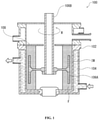
- FIG. 1 is a cross-sectional view schematically illustrating an example of a reactor used in a production method according to an aspect of the present invention.
- the reactor 100 shown in FIG. 1 is a batch type manufacturing device.
- the reactor 100 includes a reaction vessel 102.
- the reaction vessel 102 is, for example, cylindrical.
- the reaction vessel 102 typically includes an outer layer 104 for temperature control.
- the outer layer 104 is configured so that a liquid such as water can be injected. This makes it possible to control the temperature in the reaction vessel 102, particularly the temperature of the inner wall IW, which will be described later.
- the reactor 100 includes a rotary blade 106A and a rotary shaft 106B connected thereto inside the reaction vessel 102.
- the rotary blade 106A can be configured to rotate by the rotation R of the rotary shaft 106B.
- the rotary blade 106A is, for example, a cylindrical wheel having a slight gap with the inner wall IW of the reaction vessel 102.
- the wheel is typically provided with a number of holes for the formulation F to pass through.
- a dam 108 is provided on the upper side of the reactor 100. This prevents the reactants from leaking to the upper part of the reactor 100.
- the formulation F is introduced into the reaction vessel 102.
- the formulation F is stirred by rotating the rotary blade 106A through the rotary shaft 106B. Due to the centrifugal force applied to the formulation F, the formulation F is pressed against the inner wall IW while rotating. As a result, not only the above-mentioned centrifugal force but also a steady shearing force is applied to the formulation F. In this way, the formulation F is mixed while simultaneously and continuously applying centrifugal force and shear force.
- the reaction product is recovered to obtain a desired MOF.
- FIG. 2 is a cross-sectional view schematically illustrating an example of a reactor used in a production method according to another aspect of the present invention.
- the reaction device 200 shown in FIG. 2 is a continuous type manufacturing device.
- the reactor 200 includes a reaction vessel 202.
- the reaction vessel 202 is provided with two outer layers for temperature control. Specifically, in addition to the outer layer 204A having the similar structure as the outer layer 104, an additional outer layer 204B is provided on the upper part of the reaction vessel 202. This makes it possible to control the reaction temperature even in the upper part of the reaction vessel 202.
- the reactor 200 includes a rotary blade 206A and a rotary shaft 206B connected thereto inside the reaction vessel 202.
- the configurations of the rotary blade 206A and the rotary shaft 206B are the same as those described for the rotary blade 106A and the rotary shaft 106B, respectively.
- a dam 208 is provided on the upper side of the reactor 200.
- the dam 208 is smaller in size than the dam 108. This allows at least a portion of the reaction product to be delivered to the upper part of the reactor 200.
- the reactor 200 includes an injection port 210A and a discharge port 210B.
- the injection port 210A is provided in the lower part of the reactor 200 through which the formulation F can be continuously injected.
- the discharge port 210B is provided in the upper part of the reactor 200, through which at least a part of the reaction product can be discharged to the outside of the system.
- the formulation F is introduced into the reaction vessel 202 through the injection port 210A.
- the formulation F is stirred by rotating the rotary blade 206A through the rotary shaft 206B. Due to the centrifugal force applied to the formulation F, the formulation F is pressed against the inner wall IW while rotating. As a result, not only the above-mentioned centrifugal force but also a steady shearing force is applied to the formulation F. In this way, the formulation F is mixed while simultaneously and continuously applying centrifugal force and shear force.
- the reaction product obtained by this mixing is discharged from the discharge port 210B as the reaction progresses. By recovering the reaction product discharged in this way, a desired MOF is obtained.
- Specific devices for enabling the above-mentioned manufacturing method include, for example, FILMIX (Primix Corporation), Apex Disperser ZERO (Hiroshima Metal & Machinery Chemtech Co., Ltd.), and High-Shear Mixer (SILVERSON). Any device other than these may be used as long as it can simultaneously and continuously apply both centrifugal force and shear force to the formulation.
- the above production is preferably carried out while controlling the reaction temperature.
- the mixing is preferably carried out at a temperature lower than the normal boiling point of the solvent.
- the mixing is carried out, for example, at a temperature of 80°C or lower, preferably 60°C or lower. In this way, it is possible to produce MOF in a state in which the solvent in the formulation remains in appropriate amount.
- the production can be carried out while supplying at least one gas selected from the group consisting of dry air, argon, nitrogen, and oxygen into the reaction vessel. That is, in the production method according to one embodiment of the present invention, the reaction can be carried out in a closed system.
- an inert gas such as dry air, argon, and nitrogen
- an oxygen atmosphere it becomes possible to produce a MOF that is preferably synthesized in an oxygen excess atmosphere with high accuracy.
- the above production can be carried out, for example, by mixing the formulation at a linear velocity in the range of 1 to 100m/s, preferably at a linear velocity of 10 to 50m/s. If the linear velocity is too low, it may not be possible to sustainably apply shear forces to the formulation. If the linear velocity is too high, the centrifugal and shear forces applied to the formulation may be excessive.
- the metal ion donor, multidentate ligand, solvent, and optionally reaction accelerator shown in Table 1 were added to a thin film swirling high-speed mixer (FILMIX 56-L type; manufactured by Primix Corporation). Next, high-speed stirring was performed under the reaction conditions shown in Table 1. The MOFs were thereby obtained.
- the metal ion donor, multidentate ligand, solvent, and optionally reaction accelerator shown in Table 2 were added to a 100mL high pressure reaction vessel (HU-100, manufactured by SAN-AI Kagaku Co. Ltd.). Next, solvothermal synthesis was carried out using a constant temperature oven (OFP-300V; manufactured by AS ONE Corporation) under the reaction conditions shown in Table 2.
- the metal ion donor, multidentate ligand, solvent and optionally reaction accelerator shown in Table 3 were added to the 125mL grind jar.
- a stainless-steel crushing ball having a diameter of 5mm was added thereto, and ball-mill synthesis was carried out using a high-energy ball mill device (Emax; manufactured by Retsch) under the reaction conditions shown in Table 3.
- the metal ion donor and multidentate ligand shown in Table 4 were placed in a polyethylene bag and mixed thoroughly. Then, the mixture was taken out into a stainless-steel container, the solvent shown in Table 4 was added, and the mixture was further stirred and mixed. This was added to a twin-screw kneader (Process 11; manufactured by Thermo Fisher Scientific Co., Ltd.), and biaxial kneading synthesis was carried out under the reaction conditions shown in Table 4.
- the sample obtained by each of the above methods was dried under reduced pressure for 24 hours at room temperature using a vacuum desiccator (MVD-300; manufactured by AS ONE Corporation).
- the dried sample was subjected to XRD measurement using an X-ray diffractometer (MiniFlex; manufactured by Rigaku Co., Ltd.).
- X-ray diffractometer MiniFlex; manufactured by Rigaku Co., Ltd.
- at least some of the samples were heated and vacuum-dried at 140°C for 4 hours using a gas adsorption pretreatment apparatus (BERPREP-vacIII; MicrotracBEL), and then the BET specific surface area (N 2 ; 77K) was measured using a gas adsorption apparatus (BELSORP-miniX; MicrotracBEL).
- BERPREP-vacIII gas adsorption pretreatment apparatus
- BELSORP-miniX gas adsorption apparatus
- Examples 20 to 23 in Table 1 it can be seen that a higher quality MOF can in some cases be synthesized by carrying out the reaction in a dry air, nitrogen, or argon atmosphere.
- Examples 24 and 25 in Table 1 it can be seen that a higher quality MOF can in some cases be synthesized by performing the reaction in a nitrogen atmosphere.
- Examples 36 and 37 in Table 1 it can be seen that a higher quality MOF can in some cases be synthesized by performing the reaction in an oxygen atmosphere. In this way, by carrying out the reaction in a closed system as needed, it becomes possible to synthesize a wider range of MOFs.
Landscapes
- Chemical & Material Sciences (AREA)
- Organic Chemistry (AREA)
- Engineering & Computer Science (AREA)
- Oil, Petroleum & Natural Gas (AREA)
- Organic Low-Molecular-Weight Compounds And Preparation Thereof (AREA)
Abstract
Description
- The present disclosure relates to a method for producing Metal-Organic Frameworks (MOFs).
- A group of substances called Metal-Organic Framework has been attracting attention in fields such as gas storage and gas separation. The Metal-Organic Framework is a compound having a structure in which metal atoms are crosslinked with each other by an organic ligand, and typically has porosity. Metal-Organic Frameworks with porosity are also called Porous Coordination Polymers (PCPs).
- A liquid phase synthesis method such as a solution method, a hydrothermal method, a microwave method, and an ultrasonic method has been typically used as a method for producing the Metal-Organic Framework. A solid phase synthesis method using a mortar, a ball mill or the like has also been used. In recent years, a method of synthesizing Metal-Organic Frameworks using a biaxial mixing apparatus called an extruder has also been reported. In this method, a Metal-Organic Framework is produced by admixing a first reactant containing a specific metal ion donor and a second reactant containing a specific organic ligand under conditions of prolonged and sustained pressure and shear sufficient to synthesize the Metal-Organic Framework (Patent Literature 1)
- [Patent Literature 1]
US 9,815,222 B2 - However, the present inventors have found that it is sometimes difficult to synthesize a high-quality Metal-Organic Framework in a short reaction time when the above methods are used. It is therefore an object of the present invention to provide a method for producing a high-quality Metal-Organic Framework in a short time.
- The present inventors have conducted diligent studies in order to solve the above problems. As a result, the present inventors have found a new means of applying to material synthesis a technique conventionally used exclusively for dispersing and/or atomizing particles or droplets.
- Some aspects of the present invention are as described below.
- [1] A method for producing a Metal-Organic Framework, comprising: simultaneously and continuously applying a centrifugal force and a shear force to a formulation containing a metal ion donor, a multidentate ligand, and a solvent.
- [2] The method according to [1], wherein the solvent is a poor solvent for at least one of the metal ion donor and the multidentate ligand.
- [3] The method according to [1] or [2], wherein an amount of the solvent is in a range of 30 to 2000% by weight based on a total amount of the metal ion donor and the multidentate ligand.
- [4] The method according to any one of [1] to [3], wherein the method is carried out at a temperature lower than a normal boiling point of the solvent.
- [5] The method according to any one of [1] to [4], wherein the method is carried out while supplying at least one gas selected from the group consisting of dry air, argon, nitrogen, and oxygen into a reaction vessel.
- [6] The method according to any one of [1] to [5], wherein the centrifugal force is generated by stirring the formulation by rotating a rotary blade within a reaction vessel, and the shear force is generated by contact between the formulation and an inner wall of the reaction vessel due to the stirring, or by contact between particles constituting the formulation due to the stirring.
- [7] The method according to any one of [1] to [6], wherein the centrifugal force and the shear force are applied to the formulation by a thin film swirl mixing method.
- [8] The method according to any one of [1] to [7], wherein the Metal-Organic Framework is a Porous Coordination Polymer.
- The present invention makes it possible to produce a high-quality Metal-Organic Framework in a short time.
-
-
FIG. 1 is a cross-sectional view schematically illustrating an example of a reactor used in a production method according to an aspect of the present invention. -
FIG. 2 is a cross-sectional view schematically illustrating an example of a reactor used in a production method according to another aspect of the present invention. - The production methods according to an embodiment of the present invention will hereinafter be described. When referring to the drawings, the same reference numerals are given to the components exhibiting the same or similar functions, and duplicate description will be omitted.
- A method for producing a Metal-Organic Framework according to an embodiment of the present disclosure includes simultaneously and continuously applying a centrifugal force and a shear force to a formulation containing a metal ion donor, a multidentate ligand, and a solvent. The production method may comprise the steps of: preparing a formulation containing a metal ion donor, a multidentate ligand, and a solvent; and mixing the formulation while simultaneously and continuously applying a centrifugal force and a shear force to the formulation. Alternatively, this production may be carried out by sequentially adding the materials comprising the above-mentioned formulation into a reactor.
- There are no particular restrictions on the type of Metal-Organic Frameworks (MOFs) to be produced. Appropriately combining the type and coordination number of the metal ion with the type and topology of the multidentate ligand leads to a MOF with a desired structure. The MOF may contain two or more types of metal elements, and may contain two or more types of multidentate ligands. The MOF may further contain monodentate ligand(s). The MOF may be porous. In other words, the MOF may be a Porous Coordination Polymer (PCP).
- Specific examples of the MOF include those listed in the literatures below:
- Reference 1: Yabing He et al., Methane Storage in Metal-Organic Frameworks, Chem Soc Rev, 2014
- Reference 2: Jarad A. Mason et al., Evaluating metal-organic frameworks for natural gas storage, Chem. Sci., 2014, 5, 32-51
- Reference 3:
WO2019/026872 - As described above, the formulation used as a raw material for the MOF contains a metal ion donor, a multidentate ligand, and a solvent. As the metal ion donor and the multidentate ligand, any substance can be used as long as it is suitable as a combination for synthesizing a MOF.
- The metal elements of the metal ion donor can be, for example, any elements belonging to alkali metals (Group 1), alkaline earth metals (Group 2), or transition metals (Groups 3 to 12). The metal element is typically selected from the group consisting of magnesium, calcium, iron, aluminum, zinc, copper, nickel, cobalt, zirconium, and chromium. The metal ion donor may contain a plurality of metal elements. Alternatively, a plurality of metal ion donors containing different metal elements may be used in combination.
- As the metal ion donor, a metal salt is typically used. The metal ion donor may be an organic salt or an inorganic salt. The metal ion donor is typically selected from the group consisting of hydroxides, carbonates, acetates, sulfates, nitrates and chlorides. A plurality of metal ion donors containing the same metal element may be used in combination.
- The multidentate ligand is typically an organic multidentate ligand and is preferably selected from the group consisting of carboxylic acid anions, amine compounds, sulfonic acid anions, phosphate anions, and heterocyclic compounds. Examples of the carboxylic acid anion include dicarboxylic acid anion and tricarboxylic acid anion. Specific examples include anions of citric acid, malic acid, terephthalic acid, isophthalic acid, trimesic acid, and derivatives thereof. Examples of the heterocyclic compound include bipyridine, imidazole, adenine, and derivatives thereof.
- The type of solvent contained in the above formulation is not particularly limited, and a solvent generally used for synthesizing a MOF can be used. However, the solvent may preferably be a poor solvent for at least one of the metal ion donor and the multidentate ligand. With such a configuration, the formulation does not become a complete solution but becomes a semi-solid, typically a slurry, with solids remaining. This makes it possible to more effectively apply centrifugal force and shear force, which will be described later, to the above-mentioned formulation. Here, the term "poor solvent" for an object means that the solubility in a solvent of the object is 1g/50mL (=20g/L) or less at 25 °C and at atmospheric pressure. Examples of solvents that can be used include water, alcohols such as methanol and ethanol, carboxylic acids such as formic acid and acetic acid, amides such as N, N-dimethylformamide (DMF) and N, N-diethylformamide (DEF), and esters such as ethyl acetate. A mixture of a plurality of solvents may also be used.
- The amount of the solvent based on the total amount of the metal ion donor and the multidentate ligand is, for example, in a range of 30 to 2000% by weight, preferably in a range of 100 to 1000% by weight. Adopting such a configuration makes it possible to improve the production efficiency of the MOF.
- The above formulation may further contain additional substances such as reaction accelerators. The reaction accelerators are, for example, a basic substance or an acidic substance, and preferably a basic substance. Examples of the basic substance include diethylamine, triethylamine, 2,6-lutidine, pyridine, imidazole, potassium hydroxide, and sodium hydroxide. Examples of acidic substance include formic acid, acetic acid, trifluoroacetic acid, sulfuric acid, nitric acid, hydrochloric acid, and phosphoric acid. As an additional substance, a plurality of reaction accelerators may be used in combination. As an additional substance, a reaction control agent may also be added.
- The above formulation is mixed while simultaneously and continuously applying centrifugal force and shear force. This makes it possible to produce a MOF in a short time and with high quality.
- Metal-Organic Frameworks tend to be slightly brittle when compared to ordinary organometallic compounds, as implied by the term "framework" therein. Therefore, it is difficult to produce a high-quality MOF without devising a specific production method. For example, in the case of a solid-phase synthesis method using a ball mill device or the like, an extremely strong force is intermittently applied to the raw material. Therefore, the quality of the resulting MOF varies widely. Further, even in the synthesis method using an extruder, as an extremely strong shear force is locally applied to the raw material under high pressure, the similar problem is likely to occur.
- Therefore, the present inventors have considered that the above problem may be solved by simultaneously and continuously adding a centrifugal force and a shear force to the above formulation. Conventionally, such a method has been used exclusively for the purpose of dispersing and/or atomizing particles and droplets, and has not been used for material synthesis. However, the present inventors have found that the MOF can be produced in a short time and with high quality by diverting the above method to the production of the MOF.
- Examples of the method of simultaneously and continuously applying centrifugal force and shear force to the above-mentioned formulation include the following. Initially, the formulation is introduced into a reaction vessel. Next, a rotary blade provided in the reaction vessel is rotated to stir the formulation at high speed. This rotation imparts centrifugal force to the formulation. Then, by this centrifugal force, the above-mentioned compound is pressed against an inner wall of the reaction vessel. The contact between such a formulation and the inner wall of the reaction vessel imparts a shear force to the formulation. In this way, both centrifugal force and shear force are applied to the formulation simultaneously and continuously. In this state, the metal ion donor in the formulation reacts with the multidentate ligand to obtain a MOF. The shearing force may also be generated when the particles constituting the formulation come into contact with each other.
- When the above method is used, the rotation axis of the rotary blade is preferably parallel to the direction of gravity. In this case, the unevenness of the centrifugal force and the shear force applied to the formulation by rotation is reduced as compared with, for example, the case where the rotation axis is perpendicular to the gravity direction.
- One example of such a method is the thin film swirl mixing method developed by Primix Corporation. In this method, by using a thin film swirling high-speed mixer, centrifugal force and shear force can be simultaneously and continuously applied to the introduced substance. As a result, in the conventional use example, particles and droplets are dispersed and/or atomized. Specific device configurations are disclosed, for example, in
JPA2007-125454 -
FIG. 1 is a cross-sectional view schematically illustrating an example of a reactor used in a production method according to an aspect of the present invention. Thereactor 100 shown inFIG. 1 is a batch type manufacturing device. - The
reactor 100 includes areaction vessel 102. Thereaction vessel 102 is, for example, cylindrical. Thereaction vessel 102 typically includes anouter layer 104 for temperature control. Theouter layer 104 is configured so that a liquid such as water can be injected. This makes it possible to control the temperature in thereaction vessel 102, particularly the temperature of the inner wall IW, which will be described later. - The
reactor 100 includes arotary blade 106A and arotary shaft 106B connected thereto inside thereaction vessel 102. Therotary blade 106A can be configured to rotate by the rotation R of therotary shaft 106B. Therotary blade 106A is, for example, a cylindrical wheel having a slight gap with the inner wall IW of thereaction vessel 102. The wheel is typically provided with a number of holes for the formulation F to pass through. - A
dam 108 is provided on the upper side of thereactor 100. This prevents the reactants from leaking to the upper part of thereactor 100. - In the production method using the
reactor 100, initially, the formulation F is introduced into thereaction vessel 102. Next, the formulation F is stirred by rotating therotary blade 106A through therotary shaft 106B. Due to the centrifugal force applied to the formulation F, the formulation F is pressed against the inner wall IW while rotating. As a result, not only the above-mentioned centrifugal force but also a steady shearing force is applied to the formulation F. In this way, the formulation F is mixed while simultaneously and continuously applying centrifugal force and shear force. After completion of the reaction, the reaction product is recovered to obtain a desired MOF. -
FIG. 2 is a cross-sectional view schematically illustrating an example of a reactor used in a production method according to another aspect of the present invention. Thereaction device 200 shown inFIG. 2 is a continuous type manufacturing device. - The
reactor 200 includes areaction vessel 202. Thereaction vessel 202 is provided with two outer layers for temperature control. Specifically, in addition to theouter layer 204A having the similar structure as theouter layer 104, an additionalouter layer 204B is provided on the upper part of thereaction vessel 202. This makes it possible to control the reaction temperature even in the upper part of thereaction vessel 202. - The
reactor 200 includes arotary blade 206A and arotary shaft 206B connected thereto inside thereaction vessel 202. The configurations of therotary blade 206A and therotary shaft 206B are the same as those described for therotary blade 106A and therotary shaft 106B, respectively. - A
dam 208 is provided on the upper side of thereactor 200. Thedam 208 is smaller in size than thedam 108. This allows at least a portion of the reaction product to be delivered to the upper part of thereactor 200. - The
reactor 200 includes aninjection port 210A and adischarge port 210B. Theinjection port 210A is provided in the lower part of thereactor 200 through which the formulation F can be continuously injected. Thedischarge port 210B is provided in the upper part of thereactor 200, through which at least a part of the reaction product can be discharged to the outside of the system. - In the production method using the
reactor 200, initially, the formulation F is introduced into thereaction vessel 202 through theinjection port 210A. Next, the formulation F is stirred by rotating therotary blade 206A through therotary shaft 206B. Due to the centrifugal force applied to the formulation F, the formulation F is pressed against the inner wall IW while rotating. As a result, not only the above-mentioned centrifugal force but also a steady shearing force is applied to the formulation F. In this way, the formulation F is mixed while simultaneously and continuously applying centrifugal force and shear force. The reaction product obtained by this mixing is discharged from thedischarge port 210B as the reaction progresses. By recovering the reaction product discharged in this way, a desired MOF is obtained. - Specific devices for enabling the above-mentioned manufacturing method include, for example, FILMIX (Primix Corporation), Apex Disperser ZERO (Hiroshima Metal & Machinery Chemtech Co., Ltd.), and High-Shear Mixer (SILVERSON). Any device other than these may be used as long as it can simultaneously and continuously apply both centrifugal force and shear force to the formulation.
- The above production is preferably carried out while controlling the reaction temperature. In that case, the mixing is preferably carried out at a temperature lower than the normal boiling point of the solvent. The mixing is carried out, for example, at a temperature of 80°C or lower, preferably 60°C or lower. In this way, it is possible to produce MOF in a state in which the solvent in the formulation remains in appropriate amount.
- The production can be carried out while supplying at least one gas selected from the group consisting of dry air, argon, nitrogen, and oxygen into the reaction vessel. That is, in the production method according to one embodiment of the present invention, the reaction can be carried out in a closed system. For example, by performing the above production in an atmosphere of an inert gas such as dry air, argon, and nitrogen, it is possible to produce a moisture sensitive MOF with high accuracy. Alternatively, by performing the above production in an oxygen atmosphere, it becomes possible to produce a MOF that is preferably synthesized in an oxygen excess atmosphere with high accuracy.
- Further, the above production can be carried out, for example, by mixing the formulation at a linear velocity in the range of 1 to 100m/s, preferably at a linear velocity of 10 to 50m/s. If the linear velocity is too low, it may not be possible to sustainably apply shear forces to the formulation. If the linear velocity is too high, the centrifugal and shear forces applied to the formulation may be excessive.
- The metal ion donor, multidentate ligand, solvent, and optionally reaction accelerator shown in Table 1 were added to a thin film swirling high-speed mixer (FILMIX 56-L type; manufactured by Primix Corporation). Next, high-speed stirring was performed under the reaction conditions shown in Table 1. The MOFs were thereby obtained.
- The metal ion donor, multidentate ligand, solvent, and optionally reaction accelerator shown in Table 2 were added to a 100mL high pressure reaction vessel (HU-100, manufactured by SAN-AI Kagaku Co. Ltd.). Next, solvothermal synthesis was carried out using a constant temperature oven (OFP-300V; manufactured by AS ONE Corporation) under the reaction conditions shown in Table 2.
- The metal ion donor, multidentate ligand, solvent and optionally reaction accelerator shown in Table 3 were added to the 125mL grind jar. A stainless-steel crushing ball having a diameter of 5mm was added thereto, and ball-mill synthesis was carried out using a high-energy ball mill device (Emax; manufactured by Retsch) under the reaction conditions shown in Table 3.
- The metal ion donor and multidentate ligand shown in Table 4 were placed in a polyethylene bag and mixed thoroughly. Then, the mixture was taken out into a stainless-steel container, the solvent shown in Table 4 was added, and the mixture was further stirred and mixed. This was added to a twin-screw kneader (Process 11; manufactured by Thermo Fisher Scientific Co., Ltd.), and biaxial kneading synthesis was carried out under the reaction conditions shown in Table 4.
- The sample obtained by each of the above methods was dried under reduced pressure for 24 hours at room temperature using a vacuum desiccator (MVD-300; manufactured by AS ONE Corporation). The dried sample was subjected to XRD measurement using an X-ray diffractometer (MiniFlex; manufactured by Rigaku Co., Ltd.). Further, at least some of the samples were heated and vacuum-dried at 140°C for 4 hours using a gas adsorption pretreatment apparatus (BERPREP-vacIII; MicrotracBEL), and then the BET specific surface area (N2; 77K) was measured using a gas adsorption apparatus (BELSORP-miniX; MicrotracBEL).
- The quality of the obtained Metal-Organic Framework was evaluated by the presence or absence of a crystalline peak by XRD measurement and the size of the BET specific surface area SBET. These results are summarized in Tables 1 to 4.
- The following abbreviations are used in Tables 1 to 4.
- BTC: 1,3,5-benzenetricarboxylic acid (trimesic acid)
- pBDC: terephthalic acid
- iBDC: isophthalic acid
- INA: 4-pyridinecarboxylic acid
- Mim: 2-methylimidazole
- ADC: acetylenedicarboxylic acid
- DOT: dihydroxyterephthalic acid
- Fumarate: fumaric acid
- BTC3Na: trisodium 1,3,5-benzenetricarboxylate
- Further, ethanol (EtOH) having a purity of 99.5% or more was used.
- Comparing Tables 1 and 2, it can be seen that by using the production method according to the present invention, higher quality MOFs can be synthesized while significantly shortening the reaction time compared with the case of using the conventional solvothermal method. Comparing Table 1 with Tables 3 and 4, it can be seen that by using the production method according to the present invention, higher quality MOFs can be synthesized with a similar reaction time, which is comparable to the case of using the conventional ball-mill method and the biaxial kneading method.
- Further, when Examples 1 to 4 are compared as in Table 1, it can be seen that the specific surface area of the obtained MOF varies by controlling the amount of the solvent. This result suggests that the centrifugal force and shear force applied to the formulation can be optimized by controlling the viscosity of the formulation by adjusting the amount of solvent.
- Further, in Table 1, when Examples 1, 5 and 6 or Examples 8 and 9 are compared, it can be seen that higher quality MOF can be synthesized by performing the reaction at a temperature below the normal boiling point of the solvent (78.4°C in the case of ethanol, 64.7°C in the case of methanol), preferably below 60°C.
- Further, comparing Examples 20 to 23 in Table 1, it can be seen that a higher quality MOF can in some cases be synthesized by carrying out the reaction in a dry air, nitrogen, or argon atmosphere. Similarly, comparing Examples 24 and 25 in Table 1, it can be seen that a higher quality MOF can in some cases be synthesized by performing the reaction in a nitrogen atmosphere. Furthermore, comparing Examples 36 and 37 in Table 1, it can be seen that a higher quality MOF can in some cases be synthesized by performing the reaction in an oxygen atmosphere. In this way, by carrying out the reaction in a closed system as needed, it becomes possible to synthesize a wider range of MOFs.
- 100: Reactor, 102: Reaction Vessel, 104: Outer Layer, 106A: Rotary Blade, 106B: Rotary Shaft, 108: Dam, 200: Reactor, 202: Reaction Vessel, 204A: Outer Layer, 204B: Outer Layer, 206A: Rotary Blade, 206B: Rotary Shaft, 208: Dam, 210A: Injection Port, 210B: Discharge Port, F: Formulation, IW: Inner Wall, R: Rotation.


Claims (8)
- A method for producing a Metal-Organic Framework, comprising: simultaneously and continuously applying a centrifugal force and a shear force to a formulation containing a metal ion donor, a multidentate ligand, and a solvent.
- The method according to claim 1, wherein the solvent is a poor solvent for at least one of the metal ion donor and the multidentate ligand.
- The method according to claim 1 or 2, wherein an amount of the solvent is in a range of 30 to 2000% by weight based on a total amount of the metal ion donor and the multidentate ligand.
- The method according to any one of claims 1 to 3, wherein the method is carried out at a temperature lower than a normal boiling point of the solvent.
- The method according to any one of claims 1 to 4, wherein the method is carried out while supplying at least one gas selected from the group consisting of dry air, argon, nitrogen, and oxygen into a reaction vessel.
- The method according to any one of claims 1 to 5, whereinthe centrifugal force is generated by stirring the formulation by rotating a rotary blade within a reaction vessel, andthe shear force is generated by contact between the formulation and an inner wall of the reaction vessel due to the stirring, or by contact between particles constituting the formulation due to the stirring.
- The method according to any one of claims 1 to 6, wherein the centrifugal force and the shear force are applied to the formulation by a thin film swirl mixing method.
- The method according to any one of claims 1 to 7, wherein the Metal-Organic Framework is a Porous Coordination Polymer.
Applications Claiming Priority (2)
| Application Number | Priority Date | Filing Date | Title |
|---|---|---|---|
| JP2019091542 | 2019-05-14 | ||
| PCT/JP2020/019130 WO2020230820A1 (en) | 2019-05-14 | 2020-05-13 | Method for producing metal-organic structure |
Publications (2)
| Publication Number | Publication Date |
|---|---|
| EP3971160A1 true EP3971160A1 (en) | 2022-03-23 |
| EP3971160A4 EP3971160A4 (en) | 2023-08-02 |
Family
ID=73288858
Family Applications (1)
| Application Number | Title | Priority Date | Filing Date |
|---|---|---|---|
| EP20806271.1A Pending EP3971160A4 (en) | 2019-05-14 | 2020-05-13 | Method for producing metal-organic structure |
Country Status (5)
| Country | Link |
|---|---|
| US (1) | US20220220129A1 (en) |
| EP (1) | EP3971160A4 (en) |
| JP (1) | JP7686281B2 (en) |
| CN (1) | CN113825738B (en) |
| WO (1) | WO2020230820A1 (en) |
Cited By (1)
| Publication number | Priority date | Publication date | Assignee | Title |
|---|---|---|---|---|
| WO2024009979A1 (en) | 2022-07-04 | 2024-01-11 | 三井金属鉱業株式会社 | Metal-organic structure, and method for manufacturing same |
Families Citing this family (4)
| Publication number | Priority date | Publication date | Assignee | Title |
|---|---|---|---|---|
| CN112940269B (en) * | 2021-01-29 | 2023-01-06 | 华南理工大学 | A copper-based metal-organic framework material Cu-IPA for separating ethane and methane and its preparation method and application |
| WO2024024818A1 (en) * | 2022-07-28 | 2024-02-01 | 株式会社Atomis | Method for producing metal-organic structure |
| CN121969600A (en) | 2023-09-22 | 2026-05-01 | 友森股份有限公司 | Organometallic structure, method for producing the same, gas adsorbent using the same, and method for producing the gas adsorbent |
| WO2025110040A1 (en) * | 2023-11-20 | 2025-05-30 | 東洋製罐グループホールディングス株式会社 | Composite including metal organic structure and method for producing same |
Family Cites Families (15)
| Publication number | Priority date | Publication date | Assignee | Title |
|---|---|---|---|---|
| JP3134152B2 (en) * | 1999-06-17 | 2001-02-13 | 特殊機化工業株式会社 | High-speed stirring method and high-speed stirring device |
| JP2007125454A (en) * | 2005-11-01 | 2007-05-24 | Primix Copr | High-speed stirring device |
| WO2013005160A1 (en) * | 2011-07-06 | 2013-01-10 | Basf Se | Process for preparing porous metal-organic framework composed of zinc methylimidazolate |
| JP5723058B2 (en) * | 2012-03-09 | 2015-05-27 | リサーチ アンド ビジネス ファンデーション ソンギュングァン ユニバーシティResearch & Business Foundation Sungkyunkwan University | Plate-type carbon nanoparticle manufacturing method and aluminum-carbon composite material manufacturing method using the same |
| GB201309458D0 (en) * | 2013-05-27 | 2013-07-10 | Queens University Of The Belfast | Process for the Preparation of a Metal-Organic Compound |
| CN104667980B (en) * | 2015-02-17 | 2017-04-12 | 浙江工业大学 | Metal organic framework compound loaded metal-carbon oxide nano particle catalyst as well as preparation method and application thereof |
| CN108290134A (en) * | 2015-11-27 | 2018-07-17 | 巴斯夫欧洲公司 | The ultrafast high space time yield synthesis of metal-organic framework |
| JP2017144397A (en) * | 2016-02-18 | 2017-08-24 | 積水化学工業株式会社 | Carbon dioxide conversion catalyst and method for producing carboxyl group-containing compound |
| CN106076242A (en) * | 2016-06-06 | 2016-11-09 | 华南理工大学 | A kind of MOFs bimetallic adsorbing material (Fe, Co) BTC and preparation method thereof |
| CN106279009B (en) * | 2016-08-03 | 2019-09-24 | 河南大学 | Ytterbium complex and preparation method thereof as lead ion fluorescence probe |
| CN106893109B (en) * | 2017-02-17 | 2020-12-01 | 中国石油大学(华东) | A kind of continuous synthesis method of metal-organic framework compounds with stepped pore structure |
| EP3663631B1 (en) * | 2017-07-31 | 2023-10-11 | Atomis Inc. | Gas storage container |
| CN107722285B (en) * | 2017-09-15 | 2020-06-16 | 广西大学 | Hydrophobic zirconium metal organic framework material and preparation method thereof |
| CN109718734A (en) * | 2017-10-31 | 2019-05-07 | 中国石油化工股份有限公司 | The method of flow reactor and continuous multiphase reaction |
| CN109718727B (en) * | 2019-02-21 | 2021-09-03 | 西北大学 | Carbon aerogel prepared by calcining MOFs wafer, method thereof and application thereof in environmental protection and energy storage |
-
2020
- 2020-05-13 EP EP20806271.1A patent/EP3971160A4/en active Pending
- 2020-05-13 JP JP2021519462A patent/JP7686281B2/en active Active
- 2020-05-13 CN CN202080034996.1A patent/CN113825738B/en active Active
- 2020-05-13 WO PCT/JP2020/019130 patent/WO2020230820A1/en not_active Ceased
- 2020-05-13 US US17/610,160 patent/US20220220129A1/en active Pending
Cited By (1)
| Publication number | Priority date | Publication date | Assignee | Title |
|---|---|---|---|---|
| WO2024009979A1 (en) | 2022-07-04 | 2024-01-11 | 三井金属鉱業株式会社 | Metal-organic structure, and method for manufacturing same |
Also Published As
| Publication number | Publication date |
|---|---|
| JPWO2020230820A1 (en) | 2020-11-19 |
| CN113825738A (en) | 2021-12-21 |
| EP3971160A4 (en) | 2023-08-02 |
| CN113825738B (en) | 2024-07-12 |
| JP7686281B2 (en) | 2025-06-02 |
| US20220220129A1 (en) | 2022-07-14 |
| WO2020230820A1 (en) | 2020-11-19 |
Similar Documents
| Publication | Publication Date | Title |
|---|---|---|
| EP3971160A1 (en) | Method for producing metal-organic structure | |
| Głowniak et al. | Mechanochemistry: Toward green synthesis of metal–organic frameworks | |
| Titi et al. | Simple, scalable mechanosynthesis of metal–organic frameworks using liquid-assisted resonant acoustic mixing (LA-RAM) | |
| EP3004125B1 (en) | Process for the preparation of a metal-organic compound | |
| Pakamorė et al. | An ambient-temperature aqueous synthesis of zirconium-based metal–organic frameworks | |
| JP6419071B2 (en) | Method for producing nano-sized iron phosphate particles | |
| HUE028683T2 (en) | Method for the preparation of metal organic frameworks | |
| CN106883419B (en) | Rapid synthesis method and application of cobalt-based metal-organic framework material | |
| Elsaidi et al. | 3D printed MOF-based mixed matrix thin-film composite membranes | |
| CN105566654A (en) | One-dimensional structure metal-organic framework compound and preparation method thereof | |
| Moeinian et al. | How the guest molecules in nanoporous Zn (II) metal-organic framework can prevent agglomeration of ZnO nanoparticles | |
| Linder-Patton et al. | Particle size effects in the kinetic trapping of a structurally-locked form of a flexible MOF | |
| CN115232320A (en) | Green method for regulating and controlling size and morphology of MOFs crystal by adopting modifier system | |
| CN103570767B (en) | Method for synthesizing micropore ZNI-type zeolite imidazole skeleton species by ionothermal process | |
| EP2565158A2 (en) | Method for manufacturing a lithium transition metal phosphate | |
| EP1619198A1 (en) | Amorphous cefuroxime axetil and preparation process therefore | |
| WO2019057050A1 (en) | Slurry synthesis method for porous composite framework material | |
| CN101274145A (en) | Centrifugal thin film evaporator and its operating method | |
| EP4563567A1 (en) | Method for producing metal-organic structure | |
| Leszczyński et al. | Mechanochemistry unlocking stoichiometric control in alkali metal carboxylate coordination polymers | |
| WO2025063302A1 (en) | Organic metal structure, method for producing same, gas adsorption material using same, and method for producing gas adsorption material | |
| CN120718280A (en) | A zinc-based metal organic framework and its preparation method and application | |
| CN108689832A (en) | A kind of method of the porous compound skeleton material of dry powder Synthesis | |
| CN119019706A (en) | A preparation method of Fe/Mn-MOF material suitable for large-scale production | |
| CN121991375A (en) | A method for rapid synthesis of metal-organic framework materials under mild conditions |
Legal Events
| Date | Code | Title | Description |
|---|---|---|---|
| STAA | Information on the status of an ep patent application or granted ep patent |
Free format text: STATUS: THE INTERNATIONAL PUBLICATION HAS BEEN MADE |
|
| PUAI | Public reference made under article 153(3) epc to a published international application that has entered the european phase |
Free format text: ORIGINAL CODE: 0009012 |
|
| STAA | Information on the status of an ep patent application or granted ep patent |
Free format text: STATUS: REQUEST FOR EXAMINATION WAS MADE |
|
| 17P | Request for examination filed |
Effective date: 20211202 |
|
| AK | Designated contracting states |
Kind code of ref document: A1 Designated state(s): AL AT BE BG CH CY CZ DE DK EE ES FI FR GB GR HR HU IE IS IT LI LT LU LV MC MK MT NL NO PL PT RO RS SE SI SK SM TR |
|
| DAV | Request for validation of the european patent (deleted) | ||
| DAX | Request for extension of the european patent (deleted) | ||
| A4 | Supplementary search report drawn up and despatched |
Effective date: 20230629 |
|
| RIC1 | Information provided on ipc code assigned before grant |
Ipc: C07D 213/79 20060101ALI20230623BHEP Ipc: C07F 7/00 20060101ALI20230623BHEP Ipc: C07F 15/02 20060101ALI20230623BHEP Ipc: C07F 11/00 20060101ALI20230623BHEP Ipc: C07F 5/06 20060101ALI20230623BHEP Ipc: C07F 3/06 20060101ALI20230623BHEP Ipc: C07F 3/04 20060101ALI20230623BHEP Ipc: C07F 3/02 20060101ALI20230623BHEP Ipc: C07F 1/08 20060101ALI20230623BHEP Ipc: C07D 233/58 20060101ALI20230623BHEP Ipc: C07C 65/03 20060101ALI20230623BHEP Ipc: C07C 63/307 20060101ALI20230623BHEP Ipc: C07C 63/26 20060101ALI20230623BHEP Ipc: C07C 63/24 20060101ALI20230623BHEP Ipc: C07C 57/22 20060101ALI20230623BHEP Ipc: C07C 57/15 20060101ALI20230623BHEP Ipc: C07C 51/41 20060101AFI20230623BHEP |