EP3971120A1 - Sheet conveyor, sheet heater, liquid discharge apparatus, and printer - Google Patents
Sheet conveyor, sheet heater, liquid discharge apparatus, and printer Download PDFInfo
- Publication number
- EP3971120A1 EP3971120A1 EP21193014.4A EP21193014A EP3971120A1 EP 3971120 A1 EP3971120 A1 EP 3971120A1 EP 21193014 A EP21193014 A EP 21193014A EP 3971120 A1 EP3971120 A1 EP 3971120A1
- Authority
- EP
- European Patent Office
- Prior art keywords
- sheet
- conveyance
- multiple supports
- heater
- conveyance belt
- Prior art date
- Legal status (The legal status is an assumption and is not a legal conclusion. Google has not performed a legal analysis and makes no representation as to the accuracy of the status listed.)
- Pending
Links
- 239000007788 liquid Substances 0.000 title claims description 84
- 239000000463 material Substances 0.000 description 20
- 230000000052 comparative effect Effects 0.000 description 11
- 230000000694 effects Effects 0.000 description 11
- 238000010438 heat treatment Methods 0.000 description 11
- 230000006837 decompression Effects 0.000 description 10
- 239000000123 paper Substances 0.000 description 6
- 238000003491 array Methods 0.000 description 5
- 238000005192 partition Methods 0.000 description 5
- 239000000243 solution Substances 0.000 description 5
- 238000001035 drying Methods 0.000 description 4
- 238000004519 manufacturing process Methods 0.000 description 4
- 238000011144 upstream manufacturing Methods 0.000 description 4
- 239000003086 colorant Substances 0.000 description 3
- 239000000843 powder Substances 0.000 description 3
- 238000007599 discharging Methods 0.000 description 2
- 239000000839 emulsion Substances 0.000 description 2
- 239000004744 fabric Substances 0.000 description 2
- 229910052751 metal Inorganic materials 0.000 description 2
- 239000002184 metal Substances 0.000 description 2
- 239000002994 raw material Substances 0.000 description 2
- 239000002904 solvent Substances 0.000 description 2
- 239000000725 suspension Substances 0.000 description 2
- OYPRJOBELJOOCE-UHFFFAOYSA-N Calcium Chemical compound [Ca] OYPRJOBELJOOCE-UHFFFAOYSA-N 0.000 description 1
- 238000004220 aggregation Methods 0.000 description 1
- 230000002776 aggregation Effects 0.000 description 1
- 150000001413 amino acids Chemical class 0.000 description 1
- 239000000560 biocompatible material Substances 0.000 description 1
- 230000015572 biosynthetic process Effects 0.000 description 1
- 229910052791 calcium Inorganic materials 0.000 description 1
- 239000011575 calcium Substances 0.000 description 1
- 239000000919 ceramic Substances 0.000 description 1
- 238000006243 chemical reaction Methods 0.000 description 1
- 239000011248 coating agent Substances 0.000 description 1
- 238000000576 coating method Methods 0.000 description 1
- 150000001875 compounds Chemical class 0.000 description 1
- 238000001816 cooling Methods 0.000 description 1
- 238000001704 evaporation Methods 0.000 description 1
- 230000008020 evaporation Effects 0.000 description 1
- 239000000835 fiber Substances 0.000 description 1
- 239000010408 film Substances 0.000 description 1
- 239000010419 fine particle Substances 0.000 description 1
- 239000011521 glass Substances 0.000 description 1
- PCHJSUWPFVWCPO-UHFFFAOYSA-N gold Chemical compound [Au] PCHJSUWPFVWCPO-UHFFFAOYSA-N 0.000 description 1
- 229910052737 gold Inorganic materials 0.000 description 1
- 239000010931 gold Substances 0.000 description 1
- 239000008187 granular material Substances 0.000 description 1
- 230000003179 granulation Effects 0.000 description 1
- 238000005469 granulation Methods 0.000 description 1
- 238000002347 injection Methods 0.000 description 1
- 239000007924 injection Substances 0.000 description 1
- 239000010985 leather Substances 0.000 description 1
- 239000000203 mixture Substances 0.000 description 1
- 210000000056 organ Anatomy 0.000 description 1
- 239000003960 organic solvent Substances 0.000 description 1
- 239000002245 particle Substances 0.000 description 1
- 230000002093 peripheral effect Effects 0.000 description 1
- 239000012466 permeate Substances 0.000 description 1
- 239000000049 pigment Substances 0.000 description 1
- 239000004033 plastic Substances 0.000 description 1
- 102000004169 proteins and genes Human genes 0.000 description 1
- 108090000623 proteins and genes Proteins 0.000 description 1
- 239000011347 resin Substances 0.000 description 1
- 229920005989 resin Polymers 0.000 description 1
- 230000000630 rising effect Effects 0.000 description 1
- 229910052709 silver Inorganic materials 0.000 description 1
- 239000004332 silver Substances 0.000 description 1
- 239000000758 substrate Substances 0.000 description 1
- 238000004381 surface treatment Methods 0.000 description 1
- 239000004094 surface-active agent Substances 0.000 description 1
- 239000010409 thin film Substances 0.000 description 1
- XLYOFNOQVPJJNP-UHFFFAOYSA-N water Substances O XLYOFNOQVPJJNP-UHFFFAOYSA-N 0.000 description 1
- 239000002023 wood Substances 0.000 description 1
Images








Classifications
-
- B—PERFORMING OPERATIONS; TRANSPORTING
- B41—PRINTING; LINING MACHINES; TYPEWRITERS; STAMPS
- B41J—TYPEWRITERS; SELECTIVE PRINTING MECHANISMS, i.e. MECHANISMS PRINTING OTHERWISE THAN FROM A FORME; CORRECTION OF TYPOGRAPHICAL ERRORS
- B41J11/00—Devices or arrangements of selective printing mechanisms, e.g. ink-jet printers or thermal printers, for supporting or handling copy material in sheet or web form
- B41J11/0015—Devices or arrangements of selective printing mechanisms, e.g. ink-jet printers or thermal printers, for supporting or handling copy material in sheet or web form for treating before, during or after printing or for uniform coating or laminating the copy material before or after printing
- B41J11/002—Curing or drying the ink on the copy materials, e.g. by heating or irradiating
- B41J11/0021—Curing or drying the ink on the copy materials, e.g. by heating or irradiating using irradiation
-
- B—PERFORMING OPERATIONS; TRANSPORTING
- B65—CONVEYING; PACKING; STORING; HANDLING THIN OR FILAMENTARY MATERIAL
- B65H—HANDLING THIN OR FILAMENTARY MATERIAL, e.g. SHEETS, WEBS, CABLES
- B65H5/00—Feeding articles separated from piles; Feeding articles to machines
- B65H5/22—Feeding articles separated from piles; Feeding articles to machines by air-blast or suction device
- B65H5/222—Feeding articles separated from piles; Feeding articles to machines by air-blast or suction device by suction devices
- B65H5/224—Feeding articles separated from piles; Feeding articles to machines by air-blast or suction device by suction devices by suction belts
-
- B—PERFORMING OPERATIONS; TRANSPORTING
- B41—PRINTING; LINING MACHINES; TYPEWRITERS; STAMPS
- B41J—TYPEWRITERS; SELECTIVE PRINTING MECHANISMS, i.e. MECHANISMS PRINTING OTHERWISE THAN FROM A FORME; CORRECTION OF TYPOGRAPHICAL ERRORS
- B41J11/00—Devices or arrangements of selective printing mechanisms, e.g. ink-jet printers or thermal printers, for supporting or handling copy material in sheet or web form
- B41J11/0015—Devices or arrangements of selective printing mechanisms, e.g. ink-jet printers or thermal printers, for supporting or handling copy material in sheet or web form for treating before, during or after printing or for uniform coating or laminating the copy material before or after printing
- B41J11/002—Curing or drying the ink on the copy materials, e.g. by heating or irradiating
- B41J11/0022—Curing or drying the ink on the copy materials, e.g. by heating or irradiating using convection means, e.g. by using a fan for blowing or sucking air
-
- B—PERFORMING OPERATIONS; TRANSPORTING
- B41—PRINTING; LINING MACHINES; TYPEWRITERS; STAMPS
- B41J—TYPEWRITERS; SELECTIVE PRINTING MECHANISMS, i.e. MECHANISMS PRINTING OTHERWISE THAN FROM A FORME; CORRECTION OF TYPOGRAPHICAL ERRORS
- B41J11/00—Devices or arrangements of selective printing mechanisms, e.g. ink-jet printers or thermal printers, for supporting or handling copy material in sheet or web form
- B41J11/007—Conveyor belts or like feeding devices
-
- B—PERFORMING OPERATIONS; TRANSPORTING
- B41—PRINTING; LINING MACHINES; TYPEWRITERS; STAMPS
- B41J—TYPEWRITERS; SELECTIVE PRINTING MECHANISMS, i.e. MECHANISMS PRINTING OTHERWISE THAN FROM A FORME; CORRECTION OF TYPOGRAPHICAL ERRORS
- B41J11/00—Devices or arrangements of selective printing mechanisms, e.g. ink-jet printers or thermal printers, for supporting or handling copy material in sheet or web form
- B41J11/0085—Using suction for maintaining printing material flat
-
- B—PERFORMING OPERATIONS; TRANSPORTING
- B41—PRINTING; LINING MACHINES; TYPEWRITERS; STAMPS
- B41J—TYPEWRITERS; SELECTIVE PRINTING MECHANISMS, i.e. MECHANISMS PRINTING OTHERWISE THAN FROM A FORME; CORRECTION OF TYPOGRAPHICAL ERRORS
- B41J13/00—Devices or arrangements of selective printing mechanisms, e.g. ink-jet printers or thermal printers, specially adapted for supporting or handling copy material in short lengths, e.g. sheets
- B41J13/08—Conveyor bands or like feeding devices
-
- B—PERFORMING OPERATIONS; TRANSPORTING
- B65—CONVEYING; PACKING; STORING; HANDLING THIN OR FILAMENTARY MATERIAL
- B65H—HANDLING THIN OR FILAMENTARY MATERIAL, e.g. SHEETS, WEBS, CABLES
- B65H29/00—Delivering or advancing articles from machines; Advancing articles to or into piles
- B65H29/24—Delivering or advancing articles from machines; Advancing articles to or into piles by air blast or suction apparatus
- B65H29/241—Suction devices
- B65H29/242—Suction bands or belts
-
- B—PERFORMING OPERATIONS; TRANSPORTING
- B41—PRINTING; LINING MACHINES; TYPEWRITERS; STAMPS
- B41J—TYPEWRITERS; SELECTIVE PRINTING MECHANISMS, i.e. MECHANISMS PRINTING OTHERWISE THAN FROM A FORME; CORRECTION OF TYPOGRAPHICAL ERRORS
- B41J11/00—Devices or arrangements of selective printing mechanisms, e.g. ink-jet printers or thermal printers, for supporting or handling copy material in sheet or web form
- B41J11/0015—Devices or arrangements of selective printing mechanisms, e.g. ink-jet printers or thermal printers, for supporting or handling copy material in sheet or web form for treating before, during or after printing or for uniform coating or laminating the copy material before or after printing
- B41J11/002—Curing or drying the ink on the copy materials, e.g. by heating or irradiating
-
- B—PERFORMING OPERATIONS; TRANSPORTING
- B65—CONVEYING; PACKING; STORING; HANDLING THIN OR FILAMENTARY MATERIAL
- B65H—HANDLING THIN OR FILAMENTARY MATERIAL, e.g. SHEETS, WEBS, CABLES
- B65H2406/00—Means using fluid
- B65H2406/30—Suction means
- B65H2406/31—Suction box; Suction chambers
-
- B—PERFORMING OPERATIONS; TRANSPORTING
- B65—CONVEYING; PACKING; STORING; HANDLING THIN OR FILAMENTARY MATERIAL
- B65H—HANDLING THIN OR FILAMENTARY MATERIAL, e.g. SHEETS, WEBS, CABLES
- B65H2406/00—Means using fluid
- B65H2406/30—Suction means
- B65H2406/32—Suction belts
- B65H2406/322—Suction distributing means
-
- B—PERFORMING OPERATIONS; TRANSPORTING
- B65—CONVEYING; PACKING; STORING; HANDLING THIN OR FILAMENTARY MATERIAL
- B65H—HANDLING THIN OR FILAMENTARY MATERIAL, e.g. SHEETS, WEBS, CABLES
- B65H2801/00—Application field
- B65H2801/03—Image reproduction devices
- B65H2801/21—Industrial-size printers, e.g. rotary printing press
Definitions
- aspects of the present disclosure relate to a sheet conveyor, a sheet heater, a liquid discharge apparatus, and a printer.
- a printer applies a liquid onto a liquid application target such as a sheet.
- the printer includes a heater to heat the sheet on which the liquid has been applied while suctioning and conveying the sheet by a conveyance belt to accelerate drying of the liquid applied on the sheet.
- a suction conveyor includes multiple lower supports between a conveyance belt and a suction device to support a back surface of the conveyance belt from below the conveyance belt.
- the multiple lower supports extend in a conveyance direction and are arrayed in a direction perpendicular to the conveyance direction ( Japanese Patent Application Laid Open Publication No. 2018-154500 ).
- a surface of conveyance belt ruffles to form an undulation (uneven) surface between a portion that continues to contact the lower supports and a portion that does not contact the lower supports in the conveyance belt in a direction perpendicular to the conveyance direction.
- an uneven deformation occurs and remains on a sheet conveyed by the conveyance belt.
- the present embodiment has been made in view of the above problem, and an object of the present embodiment is to reduce deformation of a sheet.
- a sheet conveyor includes a conveyance belt configured to convey a sheet on a first surface of the conveyance belt in a conveyance direction, a suction device configured to suck the sheet onto the conveyance belt via the conveyance belt, and multiple supports between the conveyance belt and the suction device in a vertical direction, the multiple supports configured to support a second surface of the conveyance belt.
- a longitudinal direction of each of the multiple supports is parallel to a direction intersecting the conveyance direction, and the multiple supports are arrayed in the conveyance direction.
- the present embodiment can reduce deformation of the sheet.
- a printer 1 as a liquid discharge apparatus according to a first embodiment of the present disclosure is described with reference to FIGS. 1 and 2 .
- FIG. 1 is a schematic side view of the printer 1 according to the first embodiment.
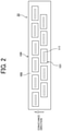
- FIG. 2 is a schematic plan view of a discharge unit of the printer 1.
- the printer 1 includes a loading unit 10 to load a sheet P into the printer 1, a pretreatment unit 20, a printing unit 30, a first dryer 40, a second dryer 50, a reverse mechanism 60, and an ejection unit 70.
- the pretreatment unit 20 serves as a liquid applier to apply a pretreatment liquid onto the sheet P.
- the pretreatment unit 20 applies, as required, a pretreatment liquid as an application liquid onto the sheet P fed (supplied) from the loading unit 10, the printing unit 30 applies a desired liquid onto the sheet P to perform required printing.
- the printer 1 After the printer 1 dries the liquid adhering to a front surface of the sheet P by the first dryer 40 and the second dryer 50, the printer 1 ejects the sheet P to the ejection unit 70 through the reverse mechanism 60 without printing on a back surface of the sheet P.
- the printer 1 may print the back surface of the sheet P after the printer 1 dries the liquid adhering to the front surface of the sheet P by the first dryer 40 and the second dryer 50 and conveys the sheet P to an upstream end of the printing unit 30 via the reversing mechanism 60, and the printer 1 then ejects the sheet P printed on both surfaces to the ejection unit 70.
- the loading unit 10 includes loading trays 11 (a lower loading tray 11A and an upper loading tray 11B) to accommodate a plurality of sheets P and feeding devices 12 (a feeding device 12A and a feeding device 12B) to separate and feed the sheets P one by one from the loading trays 11.
- the loading unit 10 supplies the sheets P to the pretreatment unit 20.
- the pretreatment unit 20 includes, e.g., a coater 21 as a treatment-liquid application unit that coats a printing surface of the sheet P with a treatment liquid having an effect of aggregation of ink particles to prevent bleed-through, for example.
- a coater 21 as a treatment-liquid application unit that coats a printing surface of the sheet P with a treatment liquid having an effect of aggregation of ink particles to prevent bleed-through, for example.
- the printing unit 30 includes a drum 31 and a liquid discharge device 32.
- the drum 31 is a bearer (rotating member) that bears the sheet P on a circumferential surface of the drum 31 and rotates.
- the liquid discharge device 32 discharges liquids toward the sheet P borne on the drum 31.
- the printing unit 30 includes transfer cylinders 34 and 35.
- the transfer cylinder 34 receives the sheet P fed from the pretreatment unit 20 and forwards the sheet P to the drum 31.
- the transfer cylinder 35 receives the sheet P conveyed by the drum 31 and forwards the sheet P to the first dryer 40.
- the transfer cylinder 34 includes a sheet gripper to grip a leading end of the sheet P conveyed from the pretreatment unit 20 to the printing unit 30.
- the sheet P thus gripped by the transfer cylinder 34 is conveyed as the transfer cylinder 34 rotates.
- the transfer cylinder 34 forwards the sheet P to the drum 31 at a position opposite (facing) the drum 31.
- the drum 31 includes a sheet gripper on a surface of the drum 31, and the leading end of the sheet P is gripped by the sheet gripper of the drum 31.
- the drum 31 includes a plurality of suction holes dispersed on a surface of the drum 31, and a suction unit generates suction airflows directed from desired suction holes of the drum 31 to an interior of the drum 31.
- the sheet gripper of the drum 31 grips the leading end of the sheet P forwarded from the transfer cylinder 34 to the drum 31, and the sheet P is attracted to and borne on the drum 31 by the suction airflows by the suction device. As the drum 31 rotates, the sheet P is conveyed.
- the liquid discharge device 32 includes discharge units 33 (discharge units 33A to 33D) to discharge liquids onto the sheet P as a liquid application device.
- discharge units 33A discharges a liquid of cyan (C)
- the discharge unit 33B discharges a liquid of magenta (M)
- the discharge unit 33C discharges a liquid of yellow (Y)
- the discharge unit 33D discharges a liquid of black (K).
- a discharge unit 33 may discharge a special liquid, that is, a liquid of spot color such as white, gold, or silver.
- each of the discharge unit 33 includes a head module 100 including a full line head.
- the head module 100 includes multiple liquid discharge heads 101 arranged in a staggered manner on a base 103.
- Each of the liquid discharge head 101 includes multiple nozzle rows, and multiple nozzles 111 are arranged in each of the nozzle rows.
- the "liquid discharge head 101" is simply referred to as a "head 101".
- the printing unit 30 controls a discharge operation of each discharge unit 33 of the liquid discharge device 32 by a drive signal corresponding to print data.
- a drive signal corresponding to print data When the sheet P borne on the drum 31 passes through a region facing the liquid discharge device 32, the liquids of respective colors are discharged from the discharge units 33 toward the sheet P, and an image corresponding to the print data is formed (printed) on the sheet P.
- the first dryer 40 includes a heating device 42 such as an infrared (IR) heater.
- the heating device 42 irradiates the sheet P, to which the liquid has been applied, with infrared rays to heat and dry the sheet P conveyed by a conveyor 41.
- the second dryer 50 includes a heating device 52 such as an ultraviolet (UV) ray irradiator.
- UV ultraviolet
- the heating device 52 of the second dryer 50 irradiates the sheet P applied with the liquid and passed through the first dryer 40 with infrared rays to heat and dry the sheet P conveyed by a conveyor 51.
- the conveyor 41 and the conveyor 51 may include a part of the same conveyance mechanism.
- the reverse mechanism 60 includes a reverse part 61 and a duplex part 62.
- the reverse part 61 reverses the sheet P that has passed through the first dryer 40 and the second dryer 50 to dry a first surface of the sheet P onto which the liquid has been applied when the printer 1 performs a duplex printing.
- the duplex part 62 feeds the reversed sheet P back to upstream of the transfer cylinder 34 of the printing unit 30.
- the reverse part 61 reverses the sheet P by switchback manner.
- the ejection unit 70 includes an ejection tray 71 on which a plurality of sheets P is stacked.
- the plurality of sheets P conveyed from the reverse mechanism 60 is sequentially stacked and held on the ejection tray 71.
- the printer 1 according to the first embodiment prints the sheet P that is a cut sheet as an example.
- the printer 1 according to the first embodiments of the present disclosure can also be applied to an apparatus using a continuous medium (web) such as continuous paper or roll paper, an apparatus using a sheet material such as wallpaper, and the like.
- the sheet heater 500 includes a sheet conveyor to convey the sheet P according to the first embodiment of the present disclosure.
- FIG. 3 is a schematic cross-sectional side view of the sheet heater 500 according to the first embodiment of the present disclosure.
- FIG. 4 is a schematic cross-sectional front view of the sheet heater 500 according to the first embodiment of the present disclosure.
- the sheet heater 500 to heat the sheet P includes a conveyance mechanism 501 as a sheet conveyor to convey the sheet P and a heater 502 that configure the heating device 52.
- the conveyance mechanism 501 includes a conveyance belt 511 that bears and conveys the sheet P.
- the conveyance mechanism 501 serves as a sheet conveyor.
- the conveyance belt 511 is an endless belt wound (stretched) between a drive roller 512 and a driven roller 513.
- the conveyance belt 511 rotates to move the sheet P.
- the conveyance mechanism 501 according to the first embodiment includes a mechanism to convey the sheet P from the printing unit 30 to the reverse mechanism 60 across the first dryer 40 and the second dryer 50 as illustrated in FIG. 1 .
- the conveyance mechanism 501 includes the conveyors 41 and 51 in FIG. 1 .
- the conveyance belt 511 is a belt that includes multiple openings from which an air is sucked by a suction chamber 514 arranged inside the conveyance belt 511.
- the suction chamber 514 serves as a suction device.
- the conveyance belt 511 may be, for example, a mesh belt, a flat belt having suction holes (openings), or the like.
- the suction chamber 514 vacuums the sheet P on the conveyance belt 511 through the openings of the conveyance belt 511.
- a suction force of the suction chamber 514 is generated by a suction device 505 (see FIG. 5 ) as described below.
- the suction chamber 514 may vacuum the sheet P by a suction blower, a fan, or the like.
- the conveyance mechanism 501 includes multiple supports 515 between the conveyance belt 511 and the suction chamber 514.
- the suction chamber 514 serves as the suction device.
- the multiple supports 515 supports a back surface of the conveyance belt 511.
- the multiple supports 515 extends in a direction intersecting the conveyance direction as indicated by arrow in FIG. 3 .
- the multiple supports 515 are arranged side by side along the conveyance direction as illustrated in FIG. 3 .
- the multiple supports 515 may have a shape of, for example, a rod, a shaft, or a linear member.
- the multiple supports are columnar rods (bars) in FIG. 6 .
- the multiple supports 515 preferably have surfaces having a curvature (curved surfaces). The surfaces having a curvature contacts the conveyance belt 511.
- the multiple supports 515 have curved surfaces to reduce contact resistance between the conveyance belt 511 and the multiple supports 515.
- the multiple supports 515 extend in a direction perpendicular to the conveyance direction (width direction) in the first embodiment. However, the multiple supports 515 may also extend obliquely with respect to the conveyance direction.
- the heater 502 includes multiple ultraviolet irradiators 521 in a housing 503.
- the multiple ultraviolet irradiators 521 arranged in a housing 503 along the conveyance direction.
- the multiple ultraviolet irradiators 521 irradiate the sheet P conveyed by the conveyance mechanism 501 with ultraviolet rays to heat the sheet P.
- the housing 503 is arranged to have a gap with the conveyance belt 511 in a vertical direction, and the gap is formed along the conveyance direction of the sheet P.
- the housing 503 includes an extension portion 503a extended lower than the conveyance belt 511 in a vertical (height) direction perpendicular to the conveyance direction of the sheet P.
- the ultraviolet irradiator 521 includes granular ultraviolet light emitting diode elements 523 (UV-LED elements) arranged in a grid pattern on an irradiation surface 522 of the ultraviolet irradiator 521. Since the UV-LED elements 523 emit light at an identical illuminance, the ultraviolet irradiator 521 uniformly emits light along the irradiation surface 522 as a whole.
- a wavelength of the ultraviolet light (UV light)
- a wavelength having a peak wavelength of 395 nm and a wavelength distribution having a full width at half maximum of about 15 nm is used.
- the ultraviolet irradiator 521 can obtain an effect of selectively heating only an image part (a part onto which the liquid is applied) and not excessively raising a temperature of a blank part (a part onto which the liquid is not applied).
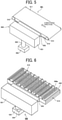
- FIG. 5 is a schematic perspective view of the conveyance mechanism 501.
- FIG. 6 is a schematic perspective view of the suction mechanism 504 forming a part of the conveyance mechanism 501.
- FIG. 7 is a cross-sectional front view of the suction chamber 514 of the suction mechanism 504 along the direction perpendicular to the conveyance direction (width direction).
- the conveyance mechanism 501 includes the conveyance belt 511, the suction chamber 514, and the suction device 505.
- the suction chamber 514 is disposed inside an inner space of the conveyance belt 511 so that the suction chamber 514 is surrounded by the conveyance belt 511.
- the suction device 505 vacuums air inside the suction chamber 514.
- the suction device 505 is disposed on a side of the suction chamber 514 in the direction perpendicular to the conveyance direction (width direction). The suction device 505 vacuums an air inside the suction chamber 514.
- the suction device 505 includes a decompression chamber 551 and a decompression device 552 that suctions an interior of the decompression chamber 551.
- the suction chamber 514 is coupled to the decompression chamber 551 with a duct 553.
- the duct 553 extends in a lateral (horizontal) direction.
- the decompression chamber 551 is coupled to the decompression device 552 with a duct 554.
- the duct 554 extends in a vertical direction.
- the suction chamber 514 includes a suction port member 540 in an upper part of the suction chamber 514.
- the suction port member 540 has multiple suction ports 540a.
- the suction chamber 514 includes a partition 542 below the suction port member 540 in the suction chamber 514.
- the partition 542 divides the suction chamber 514 into an upper chamber portion 514A and a lower chamber portion 514B.
- the partition 542 includes common suction ports 542a and 542b through which the multiple suction ports 540a commonly communicate with each other.
- the multiple common suction ports 542a and 542b are through holes and are long holes longer (extending) in the conveyance direction.
- the multiple common suction ports 542a and 542b open at positions opposed to both end portions of the suction chamber 514 in the direction perpendicular to the conveyance direction of the sheet material P (width direction).
- FIG. 7 illustrate an example in which a number of the common suction ports 542a and 542b is two. However, the number of the common suction ports may be one or three or more.
- An opening area of each of the common suction ports 542a and 542b of the partition 542 is larger than an opening area of each of the multiple suction ports 540a of the suction port member 540.
- the suction chamber 514 includes a channel member 543 coupled to the partition 542 to form suction channels 545a and 545b.
- the suction channel 545a connects the common suction port 542a to the duct 553 as a connection channel.
- the suction channel 545b connects the common suction port 542b to the duct 553.
- the suction device 505 of the suction mechanism 504 is operated to suck an interior of the decompression chamber 551 to cause the interior of the decompression chamber 551 to a negative pressure state.
- the suction device 505 generates a negative pressure inside the decompression chamber 551 to suck an interior of the suction chamber 514 through the duct 553.
- the suction device 505 sucks the interior of the suction chamber 514 to suck the lower chamber portion 514B.
- an air flow is generated in which air (gas) in the upper chamber portion 514A is sucked into the lower chamber portion 514B through the common suction ports 542a and 542b.
- the air flowing into the upper chamber portion 514A passes through the common suction ports 542a and 542b of the common suction port member 541, flows into the lower chamber portion 514B, and is sucked out from the suction chamber 514 to the decompression chamber 551 through the duct 553.
- the suction device 505 is operated to suction air from the suction port 540a, and the sheet P is attracted to the conveyance belt 511.
- the sheet P is conveyed by a circulative movement of the conveyance belt 511.
- FIGS. 9A and 9B illustrate the conveyance mechanism 501 according to the first embodiment.
- FIG. 9A is a schematic plan view of the conveyance mechanism according to the comparative example.
- FIG. 9B is a cross-sectional front view of the conveyance mechanism 501 along (corresponding to) a line A - A of FIG. 9A according to the first embodiment.
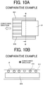
- FIGS. 10A and 10B illustrate a conveyance mechanism according to a comparative example.
- FIG. 10A is a schematic plan view of the conveyance mechanism according to the comparative example.
- FIG. 10B is a cross-sectional front view of the conveyance mechanism 501 along (corresponding to) a line B - B of FIG. 10A according to the comparative example.
- FIG. 11 is a cross-sectional front view of the conveyance mechanism according to the comparative example illustrating an effect of the conveyance mechanism according to the comparative example.
- the conveyance mechanism according to the comparative example includes multiple supports 515 between the conveyance belt 511 and the suction chamber 514.
- the multiple supports 515 contact a back surface (lower surface in FIG. 10B ) of the conveyance belt 511.
- Each of the multiple supports 515 extends in the conveyance direction as indicated by arrow in FIG. 10A .
- the multiple supports 515 are arrayed in the direction perpendicular to the conveyance direction (width direction) as illustrated in FIG. 10B .
- the sheet P when the sheet P is sucked downward by the suction chamber 514 via the conveyance belt 511, the sheet P becomes a state in which portions of the sheet P between the multiple supports 515 deform (bend) by a suction force generated by the suction chamber 514 as illustrated in FIG. 11 .
- the sheet P is deformed into an uneven shape in the direction perpendicular to the conveyance direction (width direction).
- the sheet P is conveyed by the circulative movement of the conveyance belt 511 without changing positions of the deformed parts (uneven shaped parts) of the sheet P while the sheet P is heated and dried by the heater 502.
- the moisture of the sheet P is evaporated while the sheet P is deformed into the uneven shape.
- the uneven shaped parts (deformed parts) of the sheet P remains and quality of image (image quality) on the sheet P deteriorates.
- the conveyance mechanism 501 includes the multiple supports 515, each of which extends in the direction perpendicular to the conveyance direction (width direction) as illustrated in FIG. 9A .
- the multiple supports 515 are arranged side by side in the conveyance direction as illustrated in FIG. 9A .
- the conveyance mechanism 501 (sheet conveyor) according to the first embodiment can reduce deformation of the sheet P and prevent the sheet P from having an uneven habit.
- FIG. 12 is a schematic plan view of a sheet conveyor according to the second embodiment.
- the conveyance mechanism 501 includes the multiple supports 515 divided into three portions in a direction intersecting with the conveyance direction.
- the multiple supports 515 includes three groups of multiple supports 515A, 515B, and 515C divided in the direction perpendicular to the conveyance direction (width direction) as illustrated in FIG. 12 .
- Positions of the groups (arrays) of the multiple supports 515A and 515C on both sides and a position of an array of the multiple supports 515B in a central portion of the conveyance belt 511 in the direction perpendicular to the conveyance direction (width direction) are shifted in the conveyance direction.
- the multiple supports are arrayed in the conveyance direction.
- said two or more groups of multiple supports 515A, 515B, and 515C are separated in the direction perpendicular to the conveyance direction (width direction).
- the conveyance mechanism 501 includes the groups (arrays) of the multiple supports 515A, 515B, and 515C arranged in a direction perpendicular to the conveyance direction (width direction).
- Each of the groups (arrays) of the multiple supports 515A, 515B, and 515C includes the multiple supports 515 arrayed in the conveyance direction.
- the positions of the groups (arrays) of the multiple supports 515A and 515C and the positions of the group (array) of the multiple supports 515B are shifted (staggered) in the conveyance direction.
- a positions of at least one of said two or more groups of multiple supports 515A, 515B, and 515C is shifted from a position of another of said two or more groups of multiple supports 515A, 515B, and 515C in the conveyance direction.
- any part of the sheet P in the direction perpendicular to the conveyance direction (width direction) is reliably sucked by the suction chamber 514 so that the sheet P is stably conveyed.
- the multiple supports 515 may be divided into two or more parts (two parts or four or more parts) in the direction intersecting with the conveyance direction. Further, each of a length of the divided supports 515 may be identical or different.
- a sheet heater 500 according to a sixth embodiment of the present disclosure is described with reference to FIGS. 13 and 14 .
- FIG. 13 is a schematic plan view of the sheet heater 500 according to a third embodiment of the present disclosure.
- FIG. 14 is a schematic cross-sectional side view of the sheet heater 500 according to the third embodiment of the present disclosure.
- the sheet heater 500 according to the third embodiment includes the multiple supports 515 disposed in regions other than regions immediately (directly) below the irradiation surface 522 of the ultraviolet irradiators 521 in addition to a configuration of the sheet heater 500 according to the second embodiment as illustrated in FIG. 12 .
- the multiple supports 515 are disposed in a region other than a region immediately (directly) below an irradiation region of the infrared irradiator.
- the multiple supports 515 are not directly heated by ultraviolet irradiation of the ultraviolet irradiators 521 to reduce a partial temperature rise of the conveyance belt 511.
- the sheet heater 500 can reduce temperature unevenness, drying unevenness, cockling or the like to stabilize image quality on the sheet P.
- the sheet heater 500 can reduce a partial temperature rise of the conveyance belt 511 or the like that conveys the sheet P.
- the sheet heater 500 can reduce deformation of the sheet P due to temperature unevenness and partial temperature rise of the conveyance belt 511 to increase durability of the conveyance belt 511.
- FIG. 15 is a schematic cross-sectional side view of a sheet heater 500 according to the fourth embodiment of the present disclosure.
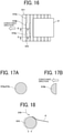
- FIG. 16 is a schematic plan view of the sheet heater 500 according to the fourth embodiment of the present disclosure.
- FIGS. 17A and 17B are cross-sectional views of one of the multiple supports 515.
- FIG. 17A is a schematic cross-sectional view of one of the multiple supports 515a and 515c along a line C - C of FIG. 16 .
- FIG. 17B is a schematic cross-sectional view of a central portion 515b of one of the multiple supports 515 along a line D - D of FIG. 16 .
- the sheet heater 500 includes a channel plate 561 between the conveyance belt 511 of the conveyance mechanism 501 and the irradiation surface 522 of the ultraviolet irradiator 521 serving as a heating unit.
- the channel plate 561 may be, for example, a general metal plate, a reflector to return the light reflected from the sheet P to the sheet P again, or the like.
- the channel plate 561 is disposed at a position close to the irradiation surface 522 to a degree in which the channel plate 561 does not block the ultraviolet light (UV light) emitted from the irradiation surface 522 of the ultraviolet irradiator 521.
- UV light ultraviolet light
- the sheet heater 500 includes an airflow generator 562 to generate an airflow 570 that flows along the irradiation surface 522.
- the airflow generator 562 is disposed between the irradiation surface 522 of the ultraviolet irradiator 521 as the heating unit and the channel plate 561.
- each of the multiple supports 515 includes end portions 515a and 515c and the central portion 515b in the direction perpendicular to the conveyance direction (width direction). Both end portions 515a and 515c of the multiple supports 515 in the direction perpendicular to the conveyance direction (width direction) have a circular cross section in the conveyance direction.
- the central portion 515b has a semicircular cross section only on a downstream side of the central portion 515b in the conveyance direction.
- the central portion 515b may have the circular cross section as illustrated in FIG. 17A in the conveyance direction, and each of end portions 515a and 515c may have a semicircular cross section as illustrated in FIG. 17B in the conveyance direction.
- FIG. 18 is a schematic cross-sectional view of the support 515 illustrating an effect of the support 515 according to the fourth embodiment.
- An airflow 570 generated by the airflow generator 562 flows toward upstream (right side in FIG. 7 ) of the sheet heater 500 in the conveyance direction as indicated by arrow in FIG. 15 along the irradiation surface 522 of the ultraviolet irradiator and the channel plate 561.
- the airflow 570 does not directly hit the sheet P on the conveyance belt 511.
- the airflow 570 does not cool the sheet P, and the sheet heater 500 can improve a drying efficiency of the sheet heater 500 to dry the sheet P.
- vapor generated from the liquid on the sheet P heated by the ultraviolet irradiation emitted from the ultraviolet irradiator 521 rises toward the irradiation surface 522 of the ultraviolet irradiator 521.
- the airflow 570 blows the vapor to upstream in the conveyance direction so that the vapor does not reach the irradiation surface 522.
- the airflow 570 containing the vapor is sucked into the suction chamber 514 by a suction airflow generated by the suction chamber 514 in a region in which the sheet P is not placed on the conveyance belt 511 and then exhausted outside the sheet heater 500.
- the sheet heater 500 blows the airflow 570 along the irradiation surface 522 of the ultraviolet irradiator 521 and sucks and discharges the airflow 570 containing the rising vapor by the suction chamber 514 toward the conveyance belt 511 opposite to the irradiation surface 522.
- the airflow 570 is discharged without directly hitting the sheet P on the conveyance belt 511 so that the drying efficiency is improved.
- the airflow 570 is generated to hit the multiple supports 515 to generate an airflow flowing along peripheral surfaces of the multiple supports 515. At this time, if a leading end of the sheet P is positioned on the multiple supports 515, the airflow 570 hits the leading end of the sheet P so that the leading end of the sheet P may be turned up by the airflow 570.
- the central portion 515b of the multiple supports 515 has the semicircular cross section only on the downstream side of the central portion 515b in the conveyance direction as illustrated in FIG. 17B .
- the airflow 570 becomes a downward flow that prevents floatation of the leading end of the sheet P so that the conveyance mechanism 501 can stably conveys the sheet P.
- FIG. 19 is a schematic partial cross-sectional side view of a main part of a sheet conveyor (conveyance mechanism 501) according to a fifth embodiment of the present disclosure.
- FIG. 20 is an enlarged partial perspective view of one of the multiple supports 515 illustrating an attachment structure of the multiple supports 515.
- FIGS. 21A to 21D are schematic partial cross-sectional side views of the sheet conveyor (conveyance mechanism 501) according to a fifth embodiment of the present disclosure to illustrate an effect of the attachment structure of the multiple supports 515.
- each of the multiple supports 515 are rotatably held by the holder 517 via the bearings 516.
- the multiple supports 515 are rotatable.
- the holder 517 and bearings 516 as illustrated in FIG. 20 can reduce sliding resistance between the conveyance belt 511 and the multiple supports 515 when the conveyance belt 511 circulates and moves.
- the joint 511a of the conveyance belt 511 can smoothly pass through the multiple supports 515 since the multiple supports 515 rotates together with the conveyance belt 511 as illustrated in FIGS. 21A to 21D .
- FIG. 22 is a schematic cross-sectional side view of a sheet heater 500 according to a sixth embodiment of the present disclosure.
- the heater 502 of the sheet heater 500 includes air blowers 581.
- the air blower 581 includes a fan 582, a channel 583, a nozzle 584, and an infrared heater 585.
- the fan 582 sucks air outside the sheet heater 500.
- the nozzle 584 is also referred to as a "blowout port”.
- the air blower 581 heats the air taken inside the channel 583 by the fan 582 with the infrared heater 585 and blows a warm air 586 from the nozzle 584 toward the sheet P through the channel 583.
- the air blower 581 reduce a vapor density in a vicinity of the sheet P to promote evaporation of the moisture in the ink while raising the temperature of the solvent and moisture in the ink applied onto the sheet P.
- the sheet heater 500 according to the sixth embodiment includes the multiple supports 515 in a region other than a region immediately (directly) below the nozzles 584 of the air blower 581 serving as an air blower as in the third embodiment (see FIG. 13 and 14 ).
- the sheet heater 500 can prevent the warm air 586 from hitting the multiple supports 515 to lift the leading end of the sheet P, thereby improving conveyance stability of the sheet heater 500.
- a "liquid" discharged from the head is not particularly limited as long as the liquid has a viscosity and surface tension of degrees dischargeable from the head.
- the viscosity of the liquid is not greater than 30 mPa ⁇ s under ordinary temperature and ordinary pressure or by heating or cooling.
- liquid examples include a solution, a suspension, or an emulsion that contains, for example, a solvent, such as water or an organic solvent, a colorant, such as dye or pigment, a functional material, such as a polymerizable compound, a resin, or a surfactant, a biocompatible material, such as DNA, amino acid, protein, or calcium, or an edible material, such as a natural colorant.
- a solvent such as water or an organic solvent
- a colorant such as dye or pigment
- a functional material such as a polymerizable compound, a resin, or a surfactant
- biocompatible material such as DNA, amino acid, protein, or calcium
- an edible material such as a natural colorant.
- Such a solution, a suspension, or an emulsion can be used for, e.g., inkjet ink, surface treatment solution, a liquid for forming components of electronic element or light-emitting element or a resist pattern of electronic circuit, or a material solution for three-dimensional fabrication.
- Examples of an energy source to generate energy to discharge liquid include a piezoelectric actuator (a laminated piezoelectric element or a thin-film piezoelectric element), a thermal actuator that employs a thermoelectric conversion element, such as a heating resistor, and an electrostatic actuator including a diaphragm and opposed electrodes.
- a piezoelectric actuator a laminated piezoelectric element or a thin-film piezoelectric element
- a thermal actuator that employs a thermoelectric conversion element, such as a heating resistor
- an electrostatic actuator including a diaphragm and opposed electrodes.
- liquid discharge apparatus examples include, not only apparatuses capable of discharging liquid to materials to which liquid can adhere, but also apparatuses to discharge a liquid toward gas or into a liquid.
- the "liquid discharge apparatus” may include units to feed, convey, and eject the material on which liquid can adhere.
- the liquid discharge apparatus may further include a pretreatment apparatus to coat a treatment liquid onto the material, and a post-treatment apparatus to coat a treatment liquid onto the material, onto which the liquid has been discharged.
- the "liquid discharge apparatus” may be, for example, an image forming apparatus to form an image on a sheet by discharging ink, or a three-dimensional fabrication apparatus to discharge a fabrication liquid to a powder layer in which powder material is formed in layers to form a three-dimensional fabrication object.
- the "liquid discharge apparatus” is not limited to an apparatus to discharge liquid to visualize meaningful images, such as letters or figures.
- the liquid discharge apparatus may be an apparatus to form arbitrary images, such as arbitrary patterns, or fabricate three-dimensional images.
- material on which liquid can adhere represents a material on which liquid is at least temporarily adhered, a material on which liquid is adhered and fixed, or a material into which liquid is adhered to permeate.
- Examples of the "material on which liquid can adhere” include recording media, such as paper sheet, recording paper, recording sheet of paper, film, and cloth, electronic component, such as electronic substrate and piezoelectric element, and media, such as powder layer, organ model, and testing cell.
- the "material on which liquid can adhere” includes any material on which liquid is adhered, unless particularly limited.
- Examples of the "material on which liquid can adhere” include any materials on which liquid can adhere even temporarily, such as paper, thread, fiber, fabric, leather, metal, plastic, glass, wood, and ceramic.
- the "liquid discharge apparatus” may be an apparatus to relatively move the head and a material on which liquid can adhere.
- liquid discharge apparatus is not limited to such an apparatus.
- the liquid discharge apparatus may be a serial head apparatus that moves the head or a line head apparatus that does not move the head.
- liquid discharge apparatus further include a treatment liquid coating apparatus to discharge a treatment liquid to a sheet to coat the treatment liquid on a sheet surface to reform the sheet surface, and an injection granulation apparatus in which a composition liquid including raw materials dispersed in a solution is injected through nozzles to granulate fine particles of the raw materials.
- image formation means “image formation”, “recording”, “printing”, “image printing”, and “fabricating” used herein may be used synonymously with each other.
Landscapes
- Engineering & Computer Science (AREA)
- Mechanical Engineering (AREA)
- Health & Medical Sciences (AREA)
- General Health & Medical Sciences (AREA)
- Toxicology (AREA)
- Ink Jet (AREA)
- Structure Of Belt Conveyors (AREA)
- Delivering By Means Of Belts And Rollers (AREA)
Abstract
A sheet conveyor (501) includes a conveyance belt (511) configured to convey a sheet on a first surface of the conveyance belt (511) in a conveyance direction, a suction device (514) configured to suck the sheet onto the conveyance belt (511) via the conveyance belt (511), and multiple supports (515) between the conveyance belt (511) and the suction device (514) in a vertical direction, the multiple supports (515) configured to support a second surface of the conveyance belt (511). A longitudinal direction of each of the multiple supports (515) is parallel to a direction intersecting the conveyance direction, and the multiple supports (515) are arrayed in the conveyance direction.
Description
- Aspects of the present disclosure relate to a sheet conveyor, a sheet heater, a liquid discharge apparatus, and a printer.
- A printer applies a liquid onto a liquid application target such as a sheet. The printer includes a heater to heat the sheet on which the liquid has been applied while suctioning and conveying the sheet by a conveyance belt to accelerate drying of the liquid applied on the sheet.
- A suction conveyor includes multiple lower supports between a conveyance belt and a suction device to support a back surface of the conveyance belt from below the conveyance belt. The multiple lower supports extend in a conveyance direction and are arrayed in a direction perpendicular to the conveyance direction (
Japanese Patent Application Laid Open Publication No. 2018-154500 - However, above-described configuration has a problem in which a portion of the conveyance belt that contacts the lower support continues to contact the lower support in the conveyance direction. Conversely, a portion of the conveyance belt that does not contact with the lower support does not continue to contact the lower support in the conveyance direction.
- Thus, a surface of conveyance belt ruffles to form an undulation (uneven) surface between a portion that continues to contact the lower supports and a portion that does not contact the lower supports in the conveyance belt in a direction perpendicular to the conveyance direction. Thus, it may occur a problem in which an uneven deformation occurs and remains on a sheet conveyed by the conveyance belt.
- The present embodiment has been made in view of the above problem, and an object of the present embodiment is to reduce deformation of a sheet.
- In an aspect of this disclosure, a sheet conveyor includes a conveyance belt configured to convey a sheet on a first surface of the conveyance belt in a conveyance direction, a suction device configured to suck the sheet onto the conveyance belt via the conveyance belt, and multiple supports between the conveyance belt and the suction device in a vertical direction, the multiple supports configured to support a second surface of the conveyance belt. A longitudinal direction of each of the multiple supports is parallel to a direction intersecting the conveyance direction, and the multiple supports are arrayed in the conveyance direction.
- The present embodiment can reduce deformation of the sheet.
- A more complete appreciation of the disclosure and many of the attendant advantages and features thereof can be readily obtained and understood from the following detailed description with reference to the accompanying drawings, wherein:
-
FIG. 1 is a schematic cross-sectional side view of a printer as a liquid discharge apparatus according to a first embodiment of the present disclosure; -
FIG. 2 is a plan view of a discharge unit of the printer; -
FIG. 3 is a schematic cross-sectional side view of a sheet heater according to the first embodiment of the present disclosure; -
FIG. 4 is a schematic cross-sectional front view of the sheet heater ofFIG. 3 ; -
FIG. 5 is a schematic perspective view of a conveyance mechanism according to the first embodiment of the present disclosure; -
FIG. 6 is a schematic perspective view of a suction mechanism forming a part of the conveyance mechanism; -
FIG. 7 is a cross-sectional front view of a suction chamber of the suction mechanism along a direction perpendicular to the conveyance direction; -
FIG. 8 is a cross-sectional front view of a suction chamber of the suction mechanism illustrating an effect of the suction mechanism; -
FIGS. 9A and 9B illustrate the conveyance mechanism according to the first embodiment of the present disclosure; -
FIGS. 10A and 10B illustrate a conveyance mechanism according to a comparative example; -
FIG. 11 is a cross-sectional front view of the conveyance mechanism according to the comparative example to illustrate an effect of the conveyance mechanism according to the comparative example; -
FIG. 12 is a schematic plan view of a sheet conveyor according to the second embodiment of the present disclosure; -
FIG. 13 is a schematic plan view of a sheet heater according to a third embodiment of the present disclosure; -
FIG. 14 is a schematic cross-sectional side view of the sheet heater according to the third embodiment of the present disclosure; -
FIG. 15 is a schematic cross-sectional side view of a sheet heater according to a fourth embodiment of the present disclosure; -
FIG. 16 is a schematic plan view of the sheet heater according to the fourth embodiment of the present disclosure; -
FIGS. 17A and 17B are cross-sectional views of one of multiple supports; -
FIG. 18 is a schematic cross-sectional view of the support illustrating an effect of the support according to the fourth embodiment; -
FIG. 19 is a schematic partial cross-sectional side view of a main part of a sheet conveyor (conveyance mechanism) according to a fifth embodiment of the present disclosure; -
FIG. 20 is an enlarged partial perspective view of one of the multiple supports illustrating an attachment structure of the multiple supports; -
FIGS. 21A to 21D are schematic partial cross-sectional side views of the sheet conveyor (conveyance mechanism) according to the fifth embodiment of the present disclosure to illustrate an effect of the attachment structure of the multiple supports; and -
FIG. 22 is a schematic cross-sectional side view of a sheet heater according to a sixth embodiment of the present disclosure. - The accompanying drawings are intended to depict embodiments of the present invention and should not be interpreted to limit the scope thereof. The accompanying drawings are not to be considered as drawn to scale unless explicitly noted. Also, identical or similar reference numerals designate identical or similar components throughout the several views.
- In describing embodiments illustrated in the drawings, specific terminology is employed for the sake of clarity. However, the disclosure of this patent specification is not intended to be limited to the specific terminology so selected and it is to be understood that each specific element includes all technical equivalents that have the same function, operate in a similar manner, and achieve similar results.
- Although the embodiments are described with technical limitations with reference to the attached drawings, such description is not intended to limit the scope of the disclosure and all of the components or elements described in the embodiments of this disclosure are not necessarily indispensable. As used herein, the singular forms "a", "an", and "the" are intended to include the plural forms as well, unless the context clearly indicates otherwise.
- Referring now to the drawings, wherein like reference numerals designate identical or corresponding parts throughout the several views, embodiments of the present disclosure are described below. A printer 1 as a liquid discharge apparatus according to a first embodiment of the present disclosure is described with reference to
FIGS. 1 and2 . -
FIG. 1 is a schematic side view of the printer 1 according to the first embodiment. -
FIG. 2 is a schematic plan view of a discharge unit of the printer 1. - The printer 1 according to the first embodiment includes a
loading unit 10 to load a sheet P into the printer 1, apretreatment unit 20, aprinting unit 30, afirst dryer 40, asecond dryer 50, areverse mechanism 60, and anejection unit 70. Thepretreatment unit 20 serves as a liquid applier to apply a pretreatment liquid onto the sheet P. - In the printer 1, the
pretreatment unit 20 applies, as required, a pretreatment liquid as an application liquid onto the sheet P fed (supplied) from theloading unit 10, theprinting unit 30 applies a desired liquid onto the sheet P to perform required printing. - After the printer 1 dries the liquid adhering to a front surface of the sheet P by the
first dryer 40 and thesecond dryer 50, the printer 1 ejects the sheet P to theejection unit 70 through thereverse mechanism 60 without printing on a back surface of the sheet P. The printer 1 may print the back surface of the sheet P after the printer 1 dries the liquid adhering to the front surface of the sheet P by thefirst dryer 40 and thesecond dryer 50 and conveys the sheet P to an upstream end of theprinting unit 30 via thereversing mechanism 60, and the printer 1 then ejects the sheet P printed on both surfaces to theejection unit 70. - The
loading unit 10 includes loading trays 11 (alower loading tray 11A and anupper loading tray 11B) to accommodate a plurality of sheets P and feeding devices 12 (afeeding device 12A and afeeding device 12B) to separate and feed the sheets P one by one from the loading trays 11. Theloading unit 10 supplies the sheets P to thepretreatment unit 20. - The
pretreatment unit 20 includes, e.g., acoater 21 as a treatment-liquid application unit that coats a printing surface of the sheet P with a treatment liquid having an effect of aggregation of ink particles to prevent bleed-through, for example. - The
printing unit 30 includes adrum 31 and aliquid discharge device 32. Thedrum 31 is a bearer (rotating member) that bears the sheet P on a circumferential surface of thedrum 31 and rotates. Theliquid discharge device 32 discharges liquids toward the sheet P borne on thedrum 31. - The
printing unit 30 includestransfer cylinders transfer cylinder 34 receives the sheet P fed from thepretreatment unit 20 and forwards the sheet P to thedrum 31. Thetransfer cylinder 35 receives the sheet P conveyed by thedrum 31 and forwards the sheet P to thefirst dryer 40. - The
transfer cylinder 34 includes a sheet gripper to grip a leading end of the sheet P conveyed from thepretreatment unit 20 to theprinting unit 30. The sheet P thus gripped by thetransfer cylinder 34 is conveyed as thetransfer cylinder 34 rotates. Thetransfer cylinder 34 forwards the sheet P to thedrum 31 at a position opposite (facing) thedrum 31. - Similarly, the
drum 31 includes a sheet gripper on a surface of thedrum 31, and the leading end of the sheet P is gripped by the sheet gripper of thedrum 31. Thedrum 31 includes a plurality of suction holes dispersed on a surface of thedrum 31, and a suction unit generates suction airflows directed from desired suction holes of thedrum 31 to an interior of thedrum 31. - The sheet gripper of the
drum 31 grips the leading end of the sheet P forwarded from thetransfer cylinder 34 to thedrum 31, and the sheet P is attracted to and borne on thedrum 31 by the suction airflows by the suction device. As thedrum 31 rotates, the sheet P is conveyed. - The
liquid discharge device 32 includes discharge units 33 (discharge units 33A to 33D) to discharge liquids onto the sheet P as a liquid application device. For example, thedischarge unit 33A discharges a liquid of cyan (C), thedischarge unit 33B discharges a liquid of magenta (M), thedischarge unit 33C discharges a liquid of yellow (Y), and thedischarge unit 33D discharges a liquid of black (K). Further, adischarge unit 33 may discharge a special liquid, that is, a liquid of spot color such as white, gold, or silver. - As illustrated in
FIG. 2 , for example, each of thedischarge unit 33 includes ahead module 100 including a full line head. Thehead module 100 includes multiple liquid discharge heads 101 arranged in a staggered manner on abase 103. Each of theliquid discharge head 101 includes multiple nozzle rows, andmultiple nozzles 111 are arranged in each of the nozzle rows. Hereinafter, the "liquid discharge head 101" is simply referred to as a "head 101". - The
printing unit 30 controls a discharge operation of eachdischarge unit 33 of theliquid discharge device 32 by a drive signal corresponding to print data. When the sheet P borne on thedrum 31 passes through a region facing theliquid discharge device 32, the liquids of respective colors are discharged from thedischarge units 33 toward the sheet P, and an image corresponding to the print data is formed (printed) on the sheet P. - The
first dryer 40 includes aheating device 42 such as an infrared (IR) heater. Theheating device 42 irradiates the sheet P, to which the liquid has been applied, with infrared rays to heat and dry the sheet P conveyed by aconveyor 41. Thesecond dryer 50 includes aheating device 52 such as an ultraviolet (UV) ray irradiator. - The
heating device 52 of thesecond dryer 50 irradiates the sheet P applied with the liquid and passed through thefirst dryer 40 with infrared rays to heat and dry the sheet P conveyed by aconveyor 51. Theconveyor 41 and theconveyor 51 may include a part of the same conveyance mechanism. - The
reverse mechanism 60 includes areverse part 61 and aduplex part 62. Thereverse part 61 reverses the sheet P that has passed through thefirst dryer 40 and thesecond dryer 50 to dry a first surface of the sheet P onto which the liquid has been applied when the printer 1 performs a duplex printing. Theduplex part 62 feeds the reversed sheet P back to upstream of thetransfer cylinder 34 of theprinting unit 30. Thereverse part 61 reverses the sheet P by switchback manner. - The
ejection unit 70 includes anejection tray 71 on which a plurality of sheets P is stacked. The plurality of sheets P conveyed from thereverse mechanism 60 is sequentially stacked and held on theejection tray 71. - The printer 1 according to the first embodiment prints the sheet P that is a cut sheet as an example. However, the printer 1 according to the first embodiments of the present disclosure can also be applied to an apparatus using a continuous medium (web) such as continuous paper or roll paper, an apparatus using a sheet material such as wallpaper, and the like.
- A
sheet heater 500 according to the first embodiment of the present disclosure is described with reference toFIGS. 3 and 4 . Thesheet heater 500 includes a sheet conveyor to convey the sheet P according to the first embodiment of the present disclosure. -
FIG. 3 is a schematic cross-sectional side view of thesheet heater 500 according to the first embodiment of the present disclosure. -
FIG. 4 is a schematic cross-sectional front view of thesheet heater 500 according to the first embodiment of the present disclosure. - The
sheet heater 500 to heat the sheet P includes aconveyance mechanism 501 as a sheet conveyor to convey the sheet P and aheater 502 that configure theheating device 52. - The
conveyance mechanism 501 includes aconveyance belt 511 that bears and conveys the sheet P. Theconveyance mechanism 501 serves as a sheet conveyor. Theconveyance belt 511 is an endless belt wound (stretched) between adrive roller 512 and a drivenroller 513. Theconveyance belt 511 rotates to move the sheet P. Theconveyance mechanism 501 according to the first embodiment includes a mechanism to convey the sheet P from theprinting unit 30 to thereverse mechanism 60 across thefirst dryer 40 and thesecond dryer 50 as illustrated inFIG. 1 . Theconveyance mechanism 501 includes theconveyors FIG. 1 . - The
conveyance belt 511 is a belt that includes multiple openings from which an air is sucked by asuction chamber 514 arranged inside theconveyance belt 511. Thesuction chamber 514 serves as a suction device. Theconveyance belt 511 may be, for example, a mesh belt, a flat belt having suction holes (openings), or the like. - The
suction chamber 514 vacuums the sheet P on theconveyance belt 511 through the openings of theconveyance belt 511. A suction force of thesuction chamber 514 is generated by a suction device 505 (seeFIG. 5 ) as described below. Thesuction chamber 514 may vacuum the sheet P by a suction blower, a fan, or the like. - The
conveyance mechanism 501 includesmultiple supports 515 between theconveyance belt 511 and thesuction chamber 514. Thesuction chamber 514 serves as the suction device. The multiple supports 515 supports a back surface of theconveyance belt 511. - The multiple supports 515 extends in a direction intersecting the conveyance direction as indicated by arrow in
FIG. 3 . Themultiple supports 515 are arranged side by side along the conveyance direction as illustrated inFIG. 3 . Here, themultiple supports 515 may have a shape of, for example, a rod, a shaft, or a linear member. The multiple supports are columnar rods (bars) inFIG. 6 . Further, themultiple supports 515 preferably have surfaces having a curvature (curved surfaces). The surfaces having a curvature contacts theconveyance belt 511. Themultiple supports 515 have curved surfaces to reduce contact resistance between theconveyance belt 511 and the multiple supports 515. - The
multiple supports 515 extend in a direction perpendicular to the conveyance direction (width direction) in the first embodiment. However, themultiple supports 515 may also extend obliquely with respect to the conveyance direction. - The
heater 502 includes multipleultraviolet irradiators 521 in ahousing 503. The multipleultraviolet irradiators 521 arranged in ahousing 503 along the conveyance direction. The multipleultraviolet irradiators 521 irradiate the sheet P conveyed by theconveyance mechanism 501 with ultraviolet rays to heat the sheet P. - As illustrated in
FIG. 3 , thehousing 503 is arranged to have a gap with theconveyance belt 511 in a vertical direction, and the gap is formed along the conveyance direction of the sheet P. As illustrated inFIG. 4 , thehousing 503 includes anextension portion 503a extended lower than theconveyance belt 511 in a vertical (height) direction perpendicular to the conveyance direction of the sheet P. - The
ultraviolet irradiator 521 includes granular ultraviolet light emitting diode elements 523 (UV-LED elements) arranged in a grid pattern on anirradiation surface 522 of theultraviolet irradiator 521. Since the UV-LED elements 523 emit light at an identical illuminance, theultraviolet irradiator 521 uniformly emits light along theirradiation surface 522 as a whole. As a wavelength of the ultraviolet light (UV light), a wavelength having a peak wavelength of 395 nm and a wavelength distribution having a full width at half maximum of about 15 nm is used. - Thus, the
ultraviolet irradiator 521 can obtain an effect of selectively heating only an image part (a part onto which the liquid is applied) and not excessively raising a temperature of a blank part (a part onto which the liquid is not applied). - Next, details of the conveyance mechanism 501 (sheet conveyor) to convey the sheet P in the first embodiment is described with reference to
FIGS. 5 to 7 . -
FIG. 5 is a schematic perspective view of theconveyance mechanism 501. -
FIG. 6 is a schematic perspective view of thesuction mechanism 504 forming a part of theconveyance mechanism 501. -
FIG. 7 is a cross-sectional front view of thesuction chamber 514 of thesuction mechanism 504 along the direction perpendicular to the conveyance direction (width direction). - The
conveyance mechanism 501 includes theconveyance belt 511, thesuction chamber 514, and thesuction device 505. Thesuction chamber 514 is disposed inside an inner space of theconveyance belt 511 so that thesuction chamber 514 is surrounded by theconveyance belt 511. Thesuction device 505 vacuums air inside thesuction chamber 514. - The
suction device 505 is disposed on a side of thesuction chamber 514 in the direction perpendicular to the conveyance direction (width direction). Thesuction device 505 vacuums an air inside thesuction chamber 514. - The
suction device 505 includes adecompression chamber 551 and adecompression device 552 that suctions an interior of thedecompression chamber 551. Thesuction chamber 514 is coupled to thedecompression chamber 551 with aduct 553. Theduct 553 extends in a lateral (horizontal) direction. Thedecompression chamber 551 is coupled to thedecompression device 552 with aduct 554. Theduct 554 extends in a vertical direction. - The
suction chamber 514 includes asuction port member 540 in an upper part of thesuction chamber 514. Thesuction port member 540 hasmultiple suction ports 540a. - The
suction chamber 514 includes apartition 542 below thesuction port member 540 in thesuction chamber 514. Thepartition 542 divides thesuction chamber 514 into anupper chamber portion 514A and alower chamber portion 514B. Thepartition 542 includescommon suction ports multiple suction ports 540a commonly communicate with each other. - The multiple
common suction ports common suction ports suction chamber 514 in the direction perpendicular to the conveyance direction of the sheet material P (width direction). -
FIG. 7 illustrate an example in which a number of thecommon suction ports - An opening area of each of the
common suction ports partition 542 is larger than an opening area of each of themultiple suction ports 540a of thesuction port member 540. - The
suction chamber 514 includes achannel member 543 coupled to thepartition 542 to formsuction channels suction channel 545a connects thecommon suction port 542a to theduct 553 as a connection channel. Thesuction channel 545b connects thecommon suction port 542b to theduct 553. - The
suction device 505 of thesuction mechanism 504 is operated to suck an interior of thedecompression chamber 551 to cause the interior of thedecompression chamber 551 to a negative pressure state. Thus, thesuction device 505 generates a negative pressure inside thedecompression chamber 551 to suck an interior of thesuction chamber 514 through theduct 553. - The
suction device 505 sucks the interior of thesuction chamber 514 to suck thelower chamber portion 514B. Thus, an air flow is generated in which air (gas) in theupper chamber portion 514A is sucked into thelower chamber portion 514B through thecommon suction ports - Accordingly, when the sheet P is on the
conveyance belt 511, an internal pressure of theupper chamber portion 514A is reduced, and the sheet P is sucked and attracted onto theconveyance belt 511. - A case in which the sheet P on the
conveyance belt 511 has a size that does not completely cover an upper portion of theupper chamber portion 514A is described below. As indicated by arrow inFIG. 8 , air flows into theupper chamber portion 514A from a portion not blocked by the sheet P through the openings of theconveyance belt 511. - The air flowing into the
upper chamber portion 514A passes through thecommon suction ports suction port member 541, flows into thelower chamber portion 514B, and is sucked out from thesuction chamber 514 to thedecompression chamber 551 through theduct 553. - In the above-described manner, the
suction device 505 is operated to suction air from thesuction port 540a, and the sheet P is attracted to theconveyance belt 511. Thus, the sheet P is conveyed by a circulative movement of theconveyance belt 511. - Next, an effect of the
sheet heater 500 according to the first embodiment is described with reference toFIGS. 9 to 11 . -
FIGS. 9A and 9B illustrate theconveyance mechanism 501 according to the first embodiment. -
FIG. 9A is a schematic plan view of the conveyance mechanism according to the comparative example. -
FIG. 9B is a cross-sectional front view of theconveyance mechanism 501 along (corresponding to) a line A - A ofFIG. 9A according to the first embodiment. -
FIGS. 10A and 10B illustrate a conveyance mechanism according to a comparative example. -
FIG. 10A is a schematic plan view of the conveyance mechanism according to the comparative example. -
FIG. 10B is a cross-sectional front view of theconveyance mechanism 501 along (corresponding to) a line B - B ofFIG. 10A according to the comparative example. -
FIG. 11 is a cross-sectional front view of the conveyance mechanism according to the comparative example illustrating an effect of the conveyance mechanism according to the comparative example. - As illustrated in
FIGS. 10A and 10B , the conveyance mechanism according to the comparative example includesmultiple supports 515 between theconveyance belt 511 and thesuction chamber 514. Themultiple supports 515 contact a back surface (lower surface inFIG. 10B ) of theconveyance belt 511. Each of themultiple supports 515 extends in the conveyance direction as indicated by arrow inFIG. 10A . Further, themultiple supports 515 are arrayed in the direction perpendicular to the conveyance direction (width direction) as illustrated inFIG. 10B . - In this comparative example, when the sheet P is sucked downward by the
suction chamber 514 via theconveyance belt 511, the sheet P becomes a state in which portions of the sheet P between themultiple supports 515 deform (bend) by a suction force generated by thesuction chamber 514 as illustrated inFIG. 11 . Thus, the sheet P is deformed into an uneven shape in the direction perpendicular to the conveyance direction (width direction). - Since the
multiple supports 515 are disposed along the conveyance direction, the sheet P is conveyed by the circulative movement of theconveyance belt 511 without changing positions of the deformed parts (uneven shaped parts) of the sheet P while the sheet P is heated and dried by theheater 502. - Therefore, when the sheet P stretched by the moisture and the moisture of the ink is heated by the
heater 502, the moisture of the sheet P is evaporated while the sheet P is deformed into the uneven shape. After the sheet P is dried, the uneven shaped parts (deformed parts) of the sheet P remains and quality of image (image quality) on the sheet P deteriorates. - Conversely, the
conveyance mechanism 501 according to the first embodiment includes themultiple supports 515, each of which extends in the direction perpendicular to the conveyance direction (width direction) as illustrated inFIG. 9A . Themultiple supports 515 are arranged side by side in the conveyance direction as illustrated inFIG. 9A . - When the sheet P is conveyed by the
conveyance belt 511, parts of the sheet P between themultiple supports 515 arrayed in the conveyance direction deform to instantaneously form a concave and convex surface (unevenness) in the sheet P. The sheet P is conveyed while the sheet P repeatedly passes themultiple supports 515 extending in the width direction and repeatedly become a concave and convex state by the circulative movement of theconveyance belt 511. Thus, the sheet P having the concave and convex surface is leveled by themultiple supports 515 extending in the width direction (direction perpendicular to the conveyance direction). - Thus, the conveyance mechanism 501 (sheet conveyor) according to the first embodiment can reduce deformation of the sheet P and prevent the sheet P from having an uneven habit.
- Next, a
sheet heater 500 according to a second embodiment of the present disclosure is described with reference toFIG. 12 . -
FIG. 12 is a schematic plan view of a sheet conveyor according to the second embodiment. - The
conveyance mechanism 501 according to the second embodiment includes themultiple supports 515 divided into three portions in a direction intersecting with the conveyance direction. Specifically, themultiple supports 515 includes three groups ofmultiple supports FIG. 12 . - Positions of the groups (arrays) of the
multiple supports multiple supports 515B in a central portion of theconveyance belt 511 in the direction perpendicular to the conveyance direction (width direction) are shifted in the conveyance direction. In each of the groups (arrays) of themultiple supports - Thus, said two or more groups of
multiple supports - Thus, the
conveyance mechanism 501 according to the second embodiment includes the groups (arrays) of themultiple supports multiple supports multiple supports 515 arrayed in the conveyance direction. The positions of the groups (arrays) of themultiple supports multiple supports 515B are shifted (staggered) in the conveyance direction. - Thus, a positions of at least one of said two or more groups of
multiple supports multiple supports - Thus, any part of the sheet P in the direction perpendicular to the conveyance direction (width direction) is reliably sucked by the
suction chamber 514 so that the sheet P is stably conveyed. - Further, the
multiple supports 515 may be divided into two or more parts (two parts or four or more parts) in the direction intersecting with the conveyance direction. Further, each of a length of the divided supports 515 may be identical or different. - A
sheet heater 500 according to a sixth embodiment of the present disclosure is described with reference toFIGS. 13 and14 . -
FIG. 13 is a schematic plan view of thesheet heater 500 according to a third embodiment of the present disclosure. -
FIG. 14 is a schematic cross-sectional side view of thesheet heater 500 according to the third embodiment of the present disclosure. - The
sheet heater 500 according to the third embodiment includes themultiple supports 515 disposed in regions other than regions immediately (directly) below theirradiation surface 522 of theultraviolet irradiators 521 in addition to a configuration of thesheet heater 500 according to the second embodiment as illustrated inFIG. 12 . When an infrared irradiator is used as the heating device as thefirst dryer 40 inFIG. 1 , themultiple supports 515 are disposed in a region other than a region immediately (directly) below an irradiation region of the infrared irradiator. - Thus, the
multiple supports 515 are not directly heated by ultraviolet irradiation of theultraviolet irradiators 521 to reduce a partial temperature rise of theconveyance belt 511. Thus, thesheet heater 500 can reduce temperature unevenness, drying unevenness, cockling or the like to stabilize image quality on the sheet P. - Further, the
sheet heater 500 can reduce a partial temperature rise of theconveyance belt 511 or the like that conveys the sheet P. Thus, thesheet heater 500 can reduce deformation of the sheet P due to temperature unevenness and partial temperature rise of theconveyance belt 511 to increase durability of theconveyance belt 511. - Next, a
sheet heater 500 according to a fourth embodiment of the present disclosure is described with reference toFIGS. 15 to 17 . -
FIG. 15 is a schematic cross-sectional side view of asheet heater 500 according to the fourth embodiment of the present disclosure. -
FIG. 16 is a schematic plan view of thesheet heater 500 according to the fourth embodiment of the present disclosure. -
FIGS. 17A and 17B are cross-sectional views of one of the multiple supports 515. -
FIG. 17A is a schematic cross-sectional view of one of themultiple supports FIG. 16 . -
FIG. 17B is a schematic cross-sectional view of acentral portion 515b of one of themultiple supports 515 along a line D - D ofFIG. 16 . - The
sheet heater 500 according to the fourth embodiment includes achannel plate 561 between theconveyance belt 511 of theconveyance mechanism 501 and theirradiation surface 522 of theultraviolet irradiator 521 serving as a heating unit. - The
channel plate 561 may be, for example, a general metal plate, a reflector to return the light reflected from the sheet P to the sheet P again, or the like. Thechannel plate 561 is disposed at a position close to theirradiation surface 522 to a degree in which thechannel plate 561 does not block the ultraviolet light (UV light) emitted from theirradiation surface 522 of theultraviolet irradiator 521. - Further, the
sheet heater 500 includes anairflow generator 562 to generate anairflow 570 that flows along theirradiation surface 522. Theairflow generator 562 is disposed between theirradiation surface 522 of theultraviolet irradiator 521 as the heating unit and thechannel plate 561. - As illustrated in
FIG. 17A , each of themultiple supports 515 includesend portions central portion 515b in the direction perpendicular to the conveyance direction (width direction). Bothend portions multiple supports 515 in the direction perpendicular to the conveyance direction (width direction) have a circular cross section in the conveyance direction. - As illustrated in
FIG. 17B , thecentral portion 515b has a semicircular cross section only on a downstream side of thecentral portion 515b in the conveyance direction. Conversely, thecentral portion 515b may have the circular cross section as illustrated inFIG. 17A in the conveyance direction, and each ofend portions FIG. 17B in the conveyance direction. - An effect of the
sheet heater 500 according to the fourth embodiment is described below with reference toFIGS. 15 to 17 andFIG. 18 . -
FIG. 18 is a schematic cross-sectional view of thesupport 515 illustrating an effect of thesupport 515 according to the fourth embodiment. - An
airflow 570 generated by theairflow generator 562 flows toward upstream (right side inFIG. 7 ) of thesheet heater 500 in the conveyance direction as indicated by arrow inFIG. 15 along theirradiation surface 522 of the ultraviolet irradiator and thechannel plate 561. Thus, theairflow 570 does not directly hit the sheet P on theconveyance belt 511. Thus, theairflow 570 does not cool the sheet P, and thesheet heater 500 can improve a drying efficiency of thesheet heater 500 to dry the sheet P. - Then, vapor generated from the liquid on the sheet P heated by the ultraviolet irradiation emitted from the
ultraviolet irradiator 521 rises toward theirradiation surface 522 of theultraviolet irradiator 521. However, theairflow 570 blows the vapor to upstream in the conveyance direction so that the vapor does not reach theirradiation surface 522. - Then, the
airflow 570 containing the vapor is sucked into thesuction chamber 514 by a suction airflow generated by thesuction chamber 514 in a region in which the sheet P is not placed on theconveyance belt 511 and then exhausted outside thesheet heater 500. - As described above, the
sheet heater 500 blows theairflow 570 along theirradiation surface 522 of theultraviolet irradiator 521 and sucks and discharges theairflow 570 containing the rising vapor by thesuction chamber 514 toward theconveyance belt 511 opposite to theirradiation surface 522. Thus, theairflow 570 is discharged without directly hitting the sheet P on theconveyance belt 511 so that the drying efficiency is improved. - As illustrated in
FIG. 18 , theairflow 570 is generated to hit themultiple supports 515 to generate an airflow flowing along peripheral surfaces of the multiple supports 515. At this time, if a leading end of the sheet P is positioned on themultiple supports 515, theairflow 570 hits the leading end of the sheet P so that the leading end of the sheet P may be turned up by theairflow 570. - Therefore, the
central portion 515b of themultiple supports 515 has the semicircular cross section only on the downstream side of thecentral portion 515b in the conveyance direction as illustrated inFIG. 17B . Thus, theairflow 570 becomes a downward flow that prevents floatation of the leading end of the sheet P so that theconveyance mechanism 501 can stably conveys the sheet P. - Next, a
sheet heater 500 according to a fifth embodiment of the present disclosure is described with reference toFIGS. 19 to 21 . -
FIG. 19 is a schematic partial cross-sectional side view of a main part of a sheet conveyor (conveyance mechanism 501) according to a fifth embodiment of the present disclosure. -
FIG. 20 is an enlarged partial perspective view of one of themultiple supports 515 illustrating an attachment structure of the multiple supports 515. -
FIGS. 21A to 21D are schematic partial cross-sectional side views of the sheet conveyor (conveyance mechanism 501) according to a fifth embodiment of the present disclosure to illustrate an effect of the attachment structure of the multiple supports 515. - Both ends of each of the
multiple supports 515 are rotatably held by theholder 517 via thebearings 516. Thus, themultiple supports 515 are rotatable. - Thus, the
holder 517 andbearings 516 as illustrated inFIG. 20 can reduce sliding resistance between theconveyance belt 511 and themultiple supports 515 when theconveyance belt 511 circulates and moves. - When the
conveyance belt 511 includes a joint 511a in theconveyance belt 511 as illustrated inFIG. 19 , the joint 511a of theconveyance belt 511 can smoothly pass through themultiple supports 515 since themultiple supports 515 rotates together with theconveyance belt 511 as illustrated inFIGS. 21A to 21D . - Next, a
sheet heater 500 according to a sixth embodiment of the present disclosure is described with reference toFIG. 22 . -
FIG. 22 is a schematic cross-sectional side view of asheet heater 500 according to a sixth embodiment of the present disclosure. - The
heater 502 of thesheet heater 500 includesair blowers 581. Theair blower 581 includes afan 582, achannel 583, anozzle 584, and aninfrared heater 585. Thefan 582 sucks air outside thesheet heater 500. Thenozzle 584 is also referred to as a "blowout port". - The
air blower 581 heats the air taken inside thechannel 583 by thefan 582 with theinfrared heater 585 and blows awarm air 586 from thenozzle 584 toward the sheet P through thechannel 583. Thus, theair blower 581 reduce a vapor density in a vicinity of the sheet P to promote evaporation of the moisture in the ink while raising the temperature of the solvent and moisture in the ink applied onto the sheet P. - The
sheet heater 500 according to the sixth embodiment includes themultiple supports 515 in a region other than a region immediately (directly) below thenozzles 584 of theair blower 581 serving as an air blower as in the third embodiment (seeFIG. 13 and14 ). - Thus, the
sheet heater 500 can prevent thewarm air 586 from hitting themultiple supports 515 to lift the leading end of the sheet P, thereby improving conveyance stability of thesheet heater 500. - It should be noted that the above-described embodiments can be combined with each other as long as there is no contradiction between the above-described embodiments.
- In the present embodiments, a "liquid" discharged from the head is not particularly limited as long as the liquid has a viscosity and surface tension of degrees dischargeable from the head.
- Preferably, the viscosity of the liquid is not greater than 30 mPa·s under ordinary temperature and ordinary pressure or by heating or cooling.
- Examples of the liquid include a solution, a suspension, or an emulsion that contains, for example, a solvent, such as water or an organic solvent, a colorant, such as dye or pigment, a functional material, such as a polymerizable compound, a resin, or a surfactant, a biocompatible material, such as DNA, amino acid, protein, or calcium, or an edible material, such as a natural colorant.
- Such a solution, a suspension, or an emulsion can be used for, e.g., inkjet ink, surface treatment solution, a liquid for forming components of electronic element or light-emitting element or a resist pattern of electronic circuit, or a material solution for three-dimensional fabrication.
- Examples of an energy source to generate energy to discharge liquid include a piezoelectric actuator (a laminated piezoelectric element or a thin-film piezoelectric element), a thermal actuator that employs a thermoelectric conversion element, such as a heating resistor, and an electrostatic actuator including a diaphragm and opposed electrodes.
- Examples of the "liquid discharge apparatus" include, not only apparatuses capable of discharging liquid to materials to which liquid can adhere, but also apparatuses to discharge a liquid toward gas or into a liquid.
- The "liquid discharge apparatus" may include units to feed, convey, and eject the material on which liquid can adhere.
- The liquid discharge apparatus may further include a pretreatment apparatus to coat a treatment liquid onto the material, and a post-treatment apparatus to coat a treatment liquid onto the material, onto which the liquid has been discharged.
- The "liquid discharge apparatus" may be, for example, an image forming apparatus to form an image on a sheet by discharging ink, or a three-dimensional fabrication apparatus to discharge a fabrication liquid to a powder layer in which powder material is formed in layers to form a three-dimensional fabrication object.
- The "liquid discharge apparatus" is not limited to an apparatus to discharge liquid to visualize meaningful images, such as letters or figures.
- For example, the liquid discharge apparatus may be an apparatus to form arbitrary images, such as arbitrary patterns, or fabricate three-dimensional images.
- The above-described term "material on which liquid can adhere" represents a material on which liquid is at least temporarily adhered, a material on which liquid is adhered and fixed, or a material into which liquid is adhered to permeate.
- Examples of the "material on which liquid can adhere" include recording media, such as paper sheet, recording paper, recording sheet of paper, film, and cloth, electronic component, such as electronic substrate and piezoelectric element, and media, such as powder layer, organ model, and testing cell.
- The "material on which liquid can adhere" includes any material on which liquid is adhered, unless particularly limited.
- Examples of the "material on which liquid can adhere" include any materials on which liquid can adhere even temporarily, such as paper, thread, fiber, fabric, leather, metal, plastic, glass, wood, and ceramic.
- The "liquid discharge apparatus" may be an apparatus to relatively move the head and a material on which liquid can adhere.
- However, the liquid discharge apparatus is not limited to such an apparatus.
- For example, the liquid discharge apparatus may be a serial head apparatus that moves the head or a line head apparatus that does not move the head.
- Examples of the "liquid discharge apparatus" further include a treatment liquid coating apparatus to discharge a treatment liquid to a sheet to coat the treatment liquid on a sheet surface to reform the sheet surface, and an injection granulation apparatus in which a composition liquid including raw materials dispersed in a solution is injected through nozzles to granulate fine particles of the raw materials.
- The terms "image formation", "recording", "printing", "image printing", and "fabricating" used herein may be used synonymously with each other.
Claims (12)
- A sheet conveyor (501) comprising:a conveyance belt (511) configured to convey a sheet on a first surface of the conveyance belt (511) in a conveyance direction;a suction device (514) configured to suck the sheet onto the conveyance belt (511) via the conveyance belt (511); andmultiple supports (515) between the conveyance belt (511) and the suction device (514) in a vertical direction, the multiple supports (515) configured to support a second surface of the conveyance belt (511),wherein a longitudinal direction of each of the multiple supports (515) is parallel to a direction intersecting the conveyance direction, andthe multiple supports (515) are arrayed in the conveyance direction.
- The sheet conveyor (501) according to claim 1,wherein the multiple supports (515) include two or more groups of multiple supports (515A, 515B, and 515C) arrayed in a direction perpendicular to the conveyance direction,said two or more groups of multiple supports (515A, 515B, and 515C) are separated in the direction perpendicular to the conveyance direction, anda position of at least one of said two or more groups of multiple supports (515A, 515B, and 515C) is shifted from a position of another of said two or more groups of multiple supports (515A, 515B, and 515C) in the conveyance direction.
- The sheet conveyor (501) according to claim 1,
wherein each of the multiple supports (515) has a shape of one of a rod, a shaft, and a linear member. - The sheet conveyor (501) according to claim 3,wherein a central portion (515b) of each of the multiple supports (515) in the direction intersecting the conveyance direction has a semicircular cross section in the conveyance direction, andboth end portions (515a and 515c) of each of the multiple supports (515) in the direction intersecting the conveyance direction has a circular cross section in the conveyance direction.
- The sheet conveyor (501) according to claim 3, wherein the multiple supports (515) have curved surfaces contacting the conveyance belt (511)
- The sheet conveyor (501) according to claim 3,
wherein the multiple supports (515) are rotatable. - The sheet conveyor (501) according to claim 1,
wherein the conveyance belt (511) is one of a mesh belt and a flat belt each having suction holes. - A sheet heater (500) comprising:the sheet conveyor (501) according to claim 1; anda heater (521) configured to heat the sheet conveyed by the conveyance belt (511).
- The sheet heater (500) according to claim 8,
wherein the heater (521) includes at least one of an infrared irradiator, an ultraviolet irradiator, and an air blower. - The sheet heater (500) according to claim 8,
wherein the multiple supports (515) are disposed in regions other than regions immediately below the heater (521). - A liquid discharge apparatus (1) comprising:a liquid application device (32) configured to apply a liquid onto a sheet; andthe sheet heater (500) according to claim 8.
- A printer (1) comprising:a printing unit (30) configured to print an image on a sheet; andthe sheet heater (500) according to claim 8.
Applications Claiming Priority (1)
| Application Number | Priority Date | Filing Date | Title |
|---|---|---|---|
| JP2020155613A JP7571437B2 (en) | 2020-09-16 | 2020-09-16 | Sheet material conveying device, sheet material heating device, liquid ejection device, printing device |
Publications (1)
| Publication Number | Publication Date |
|---|---|
| EP3971120A1 true EP3971120A1 (en) | 2022-03-23 |
Family
ID=77499712
Family Applications (1)
| Application Number | Title | Priority Date | Filing Date |
|---|---|---|---|
| EP21193014.4A Pending EP3971120A1 (en) | 2020-09-16 | 2021-08-25 | Sheet conveyor, sheet heater, liquid discharge apparatus, and printer |
Country Status (3)
| Country | Link |
|---|---|
| US (1) | US11590773B2 (en) |
| EP (1) | EP3971120A1 (en) |
| JP (1) | JP7571437B2 (en) |
Families Citing this family (3)
| Publication number | Priority date | Publication date | Assignee | Title |
|---|---|---|---|---|
| EP4342679B1 (en) | 2022-09-20 | 2025-04-16 | Ricoh Company, Ltd. | Conveyance device, drying device, image forming apparatus, and liquid discharge apparatus |
| US20240408898A1 (en) * | 2023-06-06 | 2024-12-12 | Canon Kabushiki Kaisha | Inkjet recording apparatus |
| JP2025125985A (en) | 2024-02-16 | 2025-08-28 | 富士フイルム株式会社 | Liquid jetting structure body, liquid jetting head, liquid jetting device, manufacturing method of liquid jetting structure body, and laminate |
Citations (4)
| Publication number | Priority date | Publication date | Assignee | Title |
|---|---|---|---|---|
| US6394596B1 (en) * | 1999-10-05 | 2002-05-28 | Hewlett-Packard Company | Belt-type media support for a printer |
| US20080073838A1 (en) * | 2006-09-26 | 2008-03-27 | Brother Kogyo Kabushiki Kaisha | Sheet Conveying Device |
| JP2016150794A (en) * | 2015-02-16 | 2016-08-22 | キヤノン株式会社 | Sheet transport device and recording device |
| JP2018154500A (en) | 2017-03-17 | 2018-10-04 | 株式会社リコー | Conveying device, printer and dryer |
Family Cites Families (12)
| Publication number | Priority date | Publication date | Assignee | Title |
|---|---|---|---|---|
| JP5166129B2 (en) | 2008-06-11 | 2013-03-21 | 富士フイルム株式会社 | Image forming apparatus |
| JP5146193B2 (en) | 2008-08-19 | 2013-02-20 | 株式会社リコー | Image forming apparatus |
| JP6254821B2 (en) | 2013-02-19 | 2017-12-27 | 株式会社リコー | Recording medium heating apparatus and system having the same |
| JP6225517B2 (en) | 2013-07-08 | 2017-11-08 | 株式会社リコー | Droplet discharge state detection apparatus and image forming apparatus |
| JP2015166174A (en) | 2014-02-12 | 2015-09-24 | 株式会社リコー | Liquid droplet detection device, ink jet recorder using the same, and liquid droplet detection method |
| JP6204264B2 (en) | 2014-05-20 | 2017-09-27 | 京セラドキュメントソリューションズ株式会社 | Conveying apparatus and inkjet recording apparatus |
| JP6579420B2 (en) | 2015-03-16 | 2019-09-25 | 株式会社リコー | Drying apparatus and recording medium drying system |
| EP3375619B1 (en) | 2017-03-17 | 2020-09-02 | Ricoh Company, Ltd. | Conveying device, printing apparatus, and drying device |
| JP7052249B2 (en) | 2017-08-08 | 2022-04-12 | 株式会社リコー | Image forming device, device for discharging liquid |
| US10800188B2 (en) | 2017-12-28 | 2020-10-13 | Ricoh Company, Ltd. | Sheet correcting device and printer |
| US11360414B2 (en) | 2017-12-28 | 2022-06-14 | Ricoh Company, Ltd. | Sheet correcting device and printer |
| US11285737B2 (en) | 2019-12-27 | 2022-03-29 | Ricoh Company, Ltd. | Heater, liquid discharge apparatus, and printer |
-
2020
- 2020-09-16 JP JP2020155613A patent/JP7571437B2/en active Active
-
2021
- 2021-08-25 EP EP21193014.4A patent/EP3971120A1/en active Pending
- 2021-08-30 US US17/461,832 patent/US11590773B2/en active Active
Patent Citations (4)
| Publication number | Priority date | Publication date | Assignee | Title |
|---|---|---|---|---|
| US6394596B1 (en) * | 1999-10-05 | 2002-05-28 | Hewlett-Packard Company | Belt-type media support for a printer |
| US20080073838A1 (en) * | 2006-09-26 | 2008-03-27 | Brother Kogyo Kabushiki Kaisha | Sheet Conveying Device |
| JP2016150794A (en) * | 2015-02-16 | 2016-08-22 | キヤノン株式会社 | Sheet transport device and recording device |
| JP2018154500A (en) | 2017-03-17 | 2018-10-04 | 株式会社リコー | Conveying device, printer and dryer |
Also Published As
| Publication number | Publication date |
|---|---|
| JP7571437B2 (en) | 2024-10-23 |
| JP2022049414A (en) | 2022-03-29 |
| US11590773B2 (en) | 2023-02-28 |
| US20220080749A1 (en) | 2022-03-17 |
Similar Documents
| Publication | Publication Date | Title |
|---|---|---|
| US11285737B2 (en) | Heater, liquid discharge apparatus, and printer | |
| US10562323B2 (en) | Conveying device, printing apparatus, and drying device | |
| US11590773B2 (en) | Sheet conveyor, sheet heater, liquid discharge apparatus, and printer that reduce sheet deformation via multiple supports | |
| US12145354B2 (en) | Heating device, dryer, liquid discharge apparatus, and printer | |
| JP7552258B2 (en) | Heating device, liquid ejection device, printing device | |
| US11292271B2 (en) | Heating device, liquid discharge apparatus, and printer | |
| US11752782B2 (en) | Heating device, liquid discharge apparatus, and printer | |
| JP7064708B2 (en) | Transport equipment, printing equipment and drying equipment | |
| US11597217B2 (en) | Sheet conveyor, sheet heater, liquid discharge apparatus, and printer | |
| US10442213B2 (en) | Drying device, liquid discharge apparatus, and treatment liquid applicator | |
| US11117395B2 (en) | Drying device and printer | |
| US10919321B2 (en) | Dryer and printer | |
| US11890859B2 (en) | Sheet heater, liquid discharge apparatus, and printer | |
| US11691439B2 (en) | Dryer, printer, and blower | |
| US11640128B2 (en) | Liquid discharge head, liquid discharge device, and liquid discharge apparatus | |
| US11993085B2 (en) | Heater, liquid discharge apparatus, and printer | |
| JP7155620B2 (en) | Conveying device, device for ejecting liquid | |
| JP7424062B2 (en) | Device that discharges liquid | |
| JP7491047B2 (en) | Liquid ejection device |
Legal Events
| Date | Code | Title | Description |
|---|---|---|---|
| PUAI | Public reference made under article 153(3) epc to a published international application that has entered the european phase |
Free format text: ORIGINAL CODE: 0009012 |
|
| STAA | Information on the status of an ep patent application or granted ep patent |
Free format text: STATUS: REQUEST FOR EXAMINATION WAS MADE |
|
| 17P | Request for examination filed |
Effective date: 20210825 |
|
| AK | Designated contracting states |
Kind code of ref document: A1 Designated state(s): AL AT BE BG CH CY CZ DE DK EE ES FI FR GB GR HR HU IE IS IT LI LT LU LV MC MK MT NL NO PL PT RO RS SE SI SK SM TR |
|
| STAA | Information on the status of an ep patent application or granted ep patent |
Free format text: STATUS: EXAMINATION IS IN PROGRESS |
|
| 17Q | First examination report despatched |
Effective date: 20250313 |