EP3971068A1 - Straddled vehicle - Google Patents
Straddled vehicle Download PDFInfo
- Publication number
- EP3971068A1 EP3971068A1 EP21192375.0A EP21192375A EP3971068A1 EP 3971068 A1 EP3971068 A1 EP 3971068A1 EP 21192375 A EP21192375 A EP 21192375A EP 3971068 A1 EP3971068 A1 EP 3971068A1
- Authority
- EP
- European Patent Office
- Prior art keywords
- seat
- spacer member
- ahead
- vehicle
- height
- Prior art date
- Legal status (The legal status is an assumption and is not a legal conclusion. Google has not performed a legal analysis and makes no representation as to the accuracy of the status listed.)
- Granted
Links
Images




Classifications
-
- B—PERFORMING OPERATIONS; TRANSPORTING
- B62—LAND VEHICLES FOR TRAVELLING OTHERWISE THAN ON RAILS
- B62J—CYCLE SADDLES OR SEATS; AUXILIARY DEVICES OR ACCESSORIES SPECIALLY ADAPTED TO CYCLES AND NOT OTHERWISE PROVIDED FOR, e.g. ARTICLE CARRIERS OR CYCLE PROTECTORS
- B62J1/00—Saddles or other seats for cycles; Arrangement thereof; Component parts
- B62J1/12—Box-shaped seats; Bench-type seats, e.g. dual or twin seats
-
- B—PERFORMING OPERATIONS; TRANSPORTING
- B62—LAND VEHICLES FOR TRAVELLING OTHERWISE THAN ON RAILS
- B62J—CYCLE SADDLES OR SEATS; AUXILIARY DEVICES OR ACCESSORIES SPECIALLY ADAPTED TO CYCLES AND NOT OTHERWISE PROVIDED FOR, e.g. ARTICLE CARRIERS OR CYCLE PROTECTORS
- B62J1/00—Saddles or other seats for cycles; Arrangement thereof; Component parts
- B62J1/02—Saddles resiliently mounted on the frame; Equipment therefor, e.g. springs
- B62J1/06—Saddles capable of parallel motion up and down
-
- B—PERFORMING OPERATIONS; TRANSPORTING
- B62—LAND VEHICLES FOR TRAVELLING OTHERWISE THAN ON RAILS
- B62K—CYCLES; CYCLE FRAMES; CYCLE STEERING DEVICES; RIDER-OPERATED TERMINAL CONTROLS SPECIALLY ADAPTED FOR CYCLES; CYCLE AXLE SUSPENSIONS; CYCLE SIDECARS, FORECARS, OR THE LIKE
- B62K11/00—Motorcycles, engine-assisted cycles or motor scooters with one or two wheels
- B62K11/02—Frames
- B62K11/04—Frames characterised by the engine being between front and rear wheels
-
- B—PERFORMING OPERATIONS; TRANSPORTING
- B62—LAND VEHICLES FOR TRAVELLING OTHERWISE THAN ON RAILS
- B62J—CYCLE SADDLES OR SEATS; AUXILIARY DEVICES OR ACCESSORIES SPECIALLY ADAPTED TO CYCLES AND NOT OTHERWISE PROVIDED FOR, e.g. ARTICLE CARRIERS OR CYCLE PROTECTORS
- B62J1/00—Saddles or other seats for cycles; Arrangement thereof; Component parts
- B62J1/08—Frames for saddles; Connections between saddle frames and seat pillars; Seat pillars
- B62J2001/085—Seat pillars having mechanisms to vary seat height, independently of the cycle frame
Definitions
- the present invention relates to a straddled vehicle.
- Patent Document 1 discloses a motorcycle that includes a seat height changing device.
- the seat height changing device disclosed in Patent Document 1 allows the seat height to be adjusted in two steps.
- the present invention has been made in view of the above problem, and an objective thereof is to provide a straddled vehicle having a seat height adjustment mechanism suitably restrain an interspace from emerging frontward of the seat. According to the present invention said object is solved by a straddled vehicle having the features of independent claim 1. Preferred embodiments are laid down in the dependent claims.
- a straddled vehicle comprising:
- a straddled vehicle includes the spacer member that is disposed between the seat at a relatively low height (second height) and a ahead-of-seat element. Therefore, the spacer member fills the interspace between the seat and the ahead-of-seat element, thus promoting aesthetics and restraining intrusion of water and foreign objects.
- the spacer member includes the insertion-hole closing section to close an insertion hole (first insertion hole) that is at a relatively high position of the bracket, an incorrect placement of the seat can be restrained.
- rubber As the material of the spacer member, rubber can be suitably used.
- the spacer member When the spacer member includes the tab(s) to lock to the aperture(s) of the ahead-of-seat element, the spacer member can be attached to the ahead-of-seat element in a suitable manner.
- the spacer member includes the alignment section, alignment of the spacer member with respect to the ahead-of-seat element is facilitated.
- the upper face of the spacer member is preferably located at a position lower than an imaginary plane connecting between the upper face of the ahead-of-seat element and the upper face of the seat.
- the spacer member When the spacer member includes a portion that increases in thickness in the upward direction from a lower end thereof, it is easier to adapt the shape of the spacer member to the interspace between the seat being at the second height and the ahead-of-seat element, whereby the spacer member can be reduced in weight.
- an interspace can be prevented from emerging between the seat and the spacer member in a side view of the vehicle, whereby aesthetics can be further promoted.
- the head-of-seat element may be a tank cover member that includes a portion covering a rear end portion of the fuel tank, for example.
- the tank cover member By providing the tank cover member, the shape of the fuel tank can be simplified.
- the ahead-of-seat element may be a fuel tank.
- FIG. 1 is a left side view schematically showing the motorcycle 1.
- the motorcycle 1 shown in FIG. 1 is an on-road type motorcycle.
- motorcycles according to embodiments of the present teaching are not limited to on-road type motorcycles.
- motorcycles according to embodiments of the present teaching may be motorcycles of any other type, such as a moped type, an off-road type, or a scooter type.
- front respectively mean the front, rear, right, and left as viewed from a rider on the motorcycle 1.
- up/above and down/below respectively refer to the up/above direction and the down/below direction when the motorcycle 1 is stopped on the horizontal plane.
- the motorcycle 1 includes a fuel tank 3, a main seat (which may simply be referred to as “the seat” hereinbelow) on which a rider sits, a tandem seat 26 disposed rearward of the main seat 20, an engine 80 (which is an internal combustion engine), and a body frame 70 supporting these elements.
- a main seat which may simply be referred to as “the seat” hereinbelow
- the engine 80 which is an internal combustion engine
- the body frame 70 includes a head pipe 71, a main frame 72, and a pair of rear arms 73.
- a steering shaft (not shown) is supported by the head pipe 71, with a handle bar 7 being provided at an upper portion of the steering shaft.
- Front forks 9 are provided at a lower portion of the steering shaft.
- a front wheel 10 is supported at lower end portions of the front forks 9 so as to be capable of rotating.
- the main frame 72 extends in an obliquely lower rear direction from the head pipe 71.
- the main frame 72 is linked to both of the pair of rear arms 73 via a pivot axis 74.
- a rear wheel 12 is supported at rear end portions of the pair of rear arms 73 so as to be capable of rotating.
- the body frame 70 further includes: a seat frame 75 extending in an obliquely upper rear direction from an intermediate portion of the main frame 72; and a pair of backstays 76 extending in an obliquely upper rear direction from the main frame 72, rearward of the seat frame 75.
- the seat frame 75 is located below the main seat 20 and the tandem seat 26, so as to support the main seat 20 and the tandem seat 26.
- the seat frame 75 includes a left seat frame member 75a located on the left side of the vehicle and a right seat frame member 75b located on the right side of the vehicle (see FIG. 5 ).
- the seat frame 75 and the pair of backstays 76 are connected to each other, rearward of the main frame 72.
- a grab bar 79 is attached to the seat frame 75.
- the engine 80 is located below the main frame 72.
- the engine 80 is supported by the main frame 72 in a manner not capable of swinging.
- the engine 80 includes a crankcase 82, a cylinder block 84 extending in an obliquely upper front direction from the crankcase 82, a cylinder head 86 connected to an upper portion of the cylinder block 84, and a cylinder head cover (not shown) connected to an upper portion of the cylinder head 86.
- the seat 20 is disposed rearward of the head pipe 71.
- the fuel tank 3 is located rearward of the head pipe 71 and frontward of the seat 20. In other words, the fuel tank 3 is disposed between the head pipe 71 and the seat 20.
- a tank cover member 4 is provided between the fuel tank 3 and the seat 20.
- the tank cover member 4 includes a portion covering a rear end portion of the fuel tank 3.
- the tank cover member 4 is located rearward of the head pipe 71 and frontward of the seat 20.
- any component element that is located immediately in front of the seat 20 may be referred to as an "ahead-of-seat element".
- the tank cover member 4 is an "ahead-of-seat element".
- the fuel tank 3 can be regarded as an "ahead-of-seat element".
- the motorcycle 1 includes a seat height adjustment mechanism that is capable of adjusting the height of the seat 20 in two steps. Therefore, the height of the seat 20 can be set to either a certain height (hereinafter referred to as a "first height") or another height that is lower than the first height (hereinafter referred to as the "second height").
- first height a certain height
- second height another height that is lower than the first height
- the state where the seat 20 is at the first height is referred to as a "high-position state”
- the state where the seat 20 is at the second height is referred to as a "low-position state”.
- the seat height adjustment mechanism may be able to adjust the height of the seat 20 in three or more steps.
- FIG. 2A is a side view showing the neighborhood of the seat 20 being in the high-position state. As shown in FIG. 2A , substantially no interspace exists between the seat 20 in the high-position state and the tank cover member (ahead-of-seat element) 4.
- FIG. 2B is a side view showing the neighborhood of the seat 20 being in the low-position state.
- the motorcycle 1 further includes a spacer member 30 that is disposed between the seat 20 in the low-position state (i.e., at the second height) and the tank cover member 4.
- the spacer member 30 fills the interspace between the seat 20 and the tank cover member 4.
- the seat height adjustment mechanism includes a tank bracket 5 (see FIG. 4 ), a first supporting member 40 (see FIG. 4 ), and a pair of second supporting members 50 ( FIG. 7 ) to be described below.
- FIG. 3 is a cross-sectional view of the seat 20.
- the seat 20 includes: a bottom plate 21 located at a bottom face of the seat 20; cushioning 22 supported by the bottom plate 21; and outer material 23 covering the cushioning 22.
- the bottom plate 21 includes a protrusion 21a that extends frontward.
- a plurality of load-receiving members to receive the load from the seat 20 are attached to both sides of the bottom plate 21.
- the load-receiving members may be made of rubber, for example.
- FIG. 4 is a perspective view showing a state where the seat 20, the spacer member 30, and the tank cover member 4 are removed.
- FIG. 5 is a top view showing a state where the seat 20, the tandem seat 26, and the spacer member 30 are removed.
- a cross member 77 is attached to the seat frame 75, near the fuel tank 3. The cross member 77 bridges across the left seat frame member 75a and the right seat frame member 75b.
- the tank bracket 5 is attached to the fuel tank 3 and the cross member 77. As shown in FIG. 4 , the tank bracket 5 has a plurality of insertion holes 5a and 5b into which the protrusion 21a of the bottom plate 21 can be inserted.
- the plurality of insertion holes 5a and 5b include a first insertion hole 5a and a second insertion hole 5b that is formed at a lower position than is the first insertion hole 5a.
- the protrusion 21a of the bottom plate 21 is inserted in the first insertion hole 5a when the seat 20 is in the high-position state, and when the seat 20 is in the low-position state is inserted in the second insertion hole 5b.
- the first supporting member 40 is attached to the cross member 77 and the seat frame 75.
- the first supporting member 40 may be made of a resin material, for example.
- the first supporting member 40 has a substantially H shape in a plan view, and includes a pair of front extensions 41 and a pair of rear extensions 42.
- Each of the pair of front extensions 41 has a high-position supporting surface 41a and a low-position supporting surface 41b that is located at a lower position than is the high-position supporting surface 41a.
- the low-position supporting surface 41b is located rearward of the high-position supporting surface 41a. In other words, the high-position supporting surface 41a and the low-position supporting surface 41b are arranged along the front-rear direction.
- Each of the pair of rear extensions 42 includes a high-position supporting surface 42a and a low-position supporting surface 42b that is located at a lower position than is the high-position supporting surface 42a.
- the low-position supporting surface 42b is located rearward of the high-position supporting surface 42a. In other words, the high-position supporting surface 42a and the low-position supporting surface 42b are arranged along the front-rear direction.
- FIG. 4 and FIG. 5 show the first supporting member 40 being attached to a mounting position for the low-position state.
- FIG. 6 shows the first supporting member 40 being attached to a mounting position for the high-position state. As shown in FIG. 6 , when the seat 20 is in the high-position state, the first supporting member 40 is attached more rearward than when the seat 20 is in the low-position state.
- FIG. 7 is a perspective view showing the neighborhood of the seat lock bracket 78, with the seat 20 and the tandem seat 26 removed.
- a main seat lock mechanism for securing the seat 20 to the seat frame 75 in a detachable manner and a tandem seat lock mechanism for securing the tandem seat 26 to the seat frame 75 in a detachable manner are provided.
- a pair of second supporting members 50 are disposed on both sides of the seat lock bracket 78.
- the pair of second supporting members 50 may be made of a resin material, for example.
- the pair of second supporting members 50 are attached to the seat frame 75, each extending along the front-rear direction.
- Each second supporting member 50 includes a high-position supporting surface 50a and a low-position supporting surface 50b that is located at a lower position than is the high-position supporting surface 50a.
- the low-position supporting surface 50b is located rearward of the high-position supporting surface 50a. In other words, the high-position supporting surface 50a and the low-position supporting surface 50b are arranged along the front-rear direction.
- a plurality of load-receiving members are attached to the bottom plate 21 of the seat 20, so as to protrude downward from the bottom plate 21.
- These load-receiving members are supported by the first supporting member 40 and the pair of second supporting members 50.
- the plurality of load-receiving members are supported by the high-position supporting surfaces 41a, 42a and 50a.
- the plurality of load-receiving members are supported by the low-position supporting surfaces 41b, 42b and 50b.
- the tank bracket 5, the first supporting member 40, and the pair of second supporting members 50 together function as a seat height adjustment mechanism, thus allowing the height of the seat 20 to be adjusted.
- the specific configuration of the seat height adjustment mechanism is not limited to what is exemplified herein, and various configurations that allow the height of the seat 20 to be adjusted in two or more steps may be used.
- FIG. 8A, FIG. 8B and FIG. 8C are a plan view from the rear direction, a side view from the left direction, and a plan view from the front direction, respectively, of the spacer member 30.
- FIG. 9 is a perspective view showing the neighborhood of the tank cover member 4 before the spacer member 30 is attached.
- FIG. 10 is a perspective view showing the neighborhood of the tank cover member 4 after the spacer member 30 has been attached.
- FIG. 11 is a cross-sectional view showing the spacer member 30 having been disposed between the tank cover member 4 and the seat 20.
- the spacer member 30 includes a body section 31 and an insertion-hole closing section 32.
- the spacer member 30 is made of rubber.
- the body section 31 is a portion that fills the interspace between the seat 20 and the tank cover member 4 (ahead-of-seat element)(see FIG. 11 ).
- the body section 31 has a flattened shape extending along the up-down direction and the right-left direction. As shown in FIG. 8B , the body section 31 increases in thickness (i.e., length along the front-rear direction of the vehicle) in the upward direction from a lower end thereof.
- the insertion-hole closing section 32 is a portion which extends downward from the body section 31 so as to close the first insertion hole 5a of the tank bracket 5 (see FIGS. 10 and 11 ).
- the insertion-hole closing section 32 includes: a protruding portion 32a that protrudes frontward to engage with the first insertion hole 5a; and a connecting portion 32b that interconnects between the protruding portion 32a and the body section 31.
- the tank cover member 4 includes an attachment section 4A, to which the spacer member 30 is to be attached.
- the attachment section 4 has a flattened shape extending along the up-down direction and the right-left direction.
- the attachment section 4A has two apertures (throughholes) 4a formed in positions opposing the spacer member 30 and a recess 4b.
- the spacer member 30 further includes two first tabs 33, an alignment section 34, and a second tab 35.
- the two first tabs 33 are provided on a front face of the body section 31, so as to lock into the two apertures 4a of the tank cover member 4.
- the alignment section 34 is provided on the front face of the body section 31, and is located below the first tabs 33.
- the alignment section 34 is a protruding portion that protrudes frontward from the front face of the body section 31, and as it engages with the recess 4b of the tank cover member 4, causes the spacer member 30 to be aligned with the tank cover member 4.
- the second tab 35 is provided at a lower end of the body section 31, so as to lock to a lower end of the attachment section 4A.
- an upper face 30t of the spacer member 30 is located at a position lower than an imaginary plane (indicated by dotted line DL in FIG. 11 ) connecting between an upper face 4t of the tank cover member 4 and an upper face 20t of the seat 20.
- the seat 20 overlaps a portion of the spacer member 30 in a side view of the vehicle.
- the motorcycle 1 includes the spacer member 30, which is located between the seat 20 being in the low-position state and the tank cover member 4 (ahead-of-seat element). Therefore, the spacer member 30 fills the interspace between the seat 20 and the tank cover member 4, thus promoting aesthetics and restraining intrusion of water and foreign objects.
- the spacer member 30 fills the interspace between the seat 20 and the tank cover member 4, thus promoting aesthetics and restraining intrusion of water and foreign objects.
- the spacer member 30 includes the insertion-hole closing section 32 to close the first insertion hole 5a of the tank bracket 5
- an incorrect placement of the seat 20 i.e., inserting the protrusion 21a of the bottom plate 21 into the first insertion hole 5a
- the spacer member 30 includes the insertion-hole closing section 32 to close the first insertion hole 5a of the tank bracket 5
- first tabs 33 to lock to the apertures 4a of the tank cover member 4 (ahead-of-seat element)
- the spacer member 30 can be attached to the tank cover member 4 in a suitable manner.
- the number of first tabs 33 is not limited to two as illustrated above, but may be one or greater.
- the spacer member 30 includes the alignment section 34, alignment of the spacer member 30 with respect to the tank cover member 4 (ahead-of-seat element) is facilitated.
- the upper face 30t of the spacer member 30 is preferably located at a position lower than an imaginary plane connecting between the upper face 4t of the tank cover member 4 (ahead-of-seat element) and the upper face 20t of the seat 20.
- the spacer member 30 When the spacer member 30 includes a portion that increases in thickness in the upward direction from a lower end thereof, it is easier to adapt the shape of the spacer member 30 to the interspace between the seat 20 being in the low-position state (i.e., at the second height) and the tank cover member 4, whereby the spacer member 30 can be reduced in weight.
- an interspace can be prevented from emerging between the seat 20 and the spacer member 30 in a side view of the vehicle, whereby aesthetics can be further promoted.
- the spacer member 30 rubber can be suitably used.
- the material of the spacer member 30 is not limited to rubber.
- the spacer member 30 may be made of a resin material.
- the spacer member 30 may have a different shape as compared to when it is made of rubber. For example, a portion of the body section 31 that is not exposed to the outside may be omitted (thinned out) as appropriate.
- the tank cover member 4 may be omitted; in other words, the fuel tank 3 may be the ahead-of-seat element.
- the spacer member 30 is to be attached to the fuel tank 3.
- the tank cover member 4 is provided (i.e., the ahead-of-seat element is the tank cover member 4), there is an advantage of being able to simplify the shape of the fuel tank 3.
- the motorcycle 1 has been exemplified as a straddled vehicle, the straddled vehicle is meant to be any automotive vehicle on which a rider straddles and rides, without being limited to motorcycles.
- the straddled vehicle may be a three-wheeled motorcycle (LMW) of a type whose direction of travel is changed as its body is tilted, or an ATV (All Terrain Vehicle) such as a buggy.
- LMW three-wheeled motorcycle
- ATV All Terrain Vehicle
- a straddled vehicle includes: a body frame 70 including a head pipe 71; a seat 20 on which a rider sits, the seat 20 being disposed rearward of the head pipe 71; an ahead-of-seat element located rearward of the head pipe 71 and frontward of the seat 20; and a seat height adjustment mechanism capable of adjusting height of the seat 20 in at least two steps.
- the straddled vehicle further comprises a spacer member 30 to be disposed between the ahead-of-seat element and the seat 20 being at a second height which is lower than the first height, the spacer member 30 filling an interspace between the ahead-of-seat element and the seat 20 being at the second height.
- a straddled vehicle includes the spacer member 30 that is disposed between the seat 20 at a relatively low height (second height) and a ahead-of-seat element. Therefore, the spacer member 30 fills the interspace between the seat 20 and the ahead-of-seat element, thus promoting aesthetics and restraining intrusion of water and foreign objects.
- the seat 20 includes a bottom plate 21 located at a bottom face of the seat 20; the bottom plate 21 includes a protrusion 21a that extends frontward; the seat height adjustment mechanism includes a bracket 5 having a plurality of insertion holes 5a and 5b into which the protrusion 21a of the bottom plate 21 is insertable; the plurality of insertion holes 5a and 5b include a first insertion hole 5a and a second insertion hole 5b that is formed at a lower position than is the first insertion hole 5a; and the spacer member 30 includes: a body section 31 which fills the interspace between the ahead-of-seat element and the seat 20 being at the second height; and an insertion-hole closing section 32 extending downward from the body section 31 to close the first insertion hole 5a.
- the spacer member 30 includes the insertion-hole closing section 32 to close an insertion hole (first insertion hole 5a) that is at a relatively high position of the bracket 5, an incorrect placement of the seat 20 can be restrained.
- the spacer member 30 is made of rubber.
- rubber As the material of the spacer member 30, rubber can be suitably used.
- the ahead-of-seat element has at least one aperture made in a position opposing the spacer member 30; and the spacer member 30 includes at least one tab 33 to lock to the at least one aperture.
- the spacer member 30 When the spacer member 30 includes the tab(s) 33 to lock to the aperture(s) of the ahead-of-seat element, the spacer member 30 can be attached to the ahead-of-seat element in a suitable manner.
- the spacer member 30 includes an alignment section 34 that causes the spacer member 30 to be aligned with the ahead-of-seat element.
- the spacer member 30 includes the alignment section 34, alignment of the spacer member 30 with respect to the ahead-of-seat element is facilitated.
- an upper face 30t of the spacer member 30 is located at a position lower than an imaginary plane connecting between an upper face of the ahead-of-seat element and an upper face 20t of the seat 20.
- the upper face 30t of the spacer member 30 is preferably located at a position lower than an imaginary plane connecting between the upper face of the ahead-of-seat element and the upper face 20t of the seat 20.
- the spacer member 30 includes a portion that increases in thickness in an upward direction from a lower end of the spacer member 30.
- the spacer member 30 includes a portion that increases in thickness in the upward direction from a lower end thereof, it is easier to adapt the shape of the spacer member 30 to the interspace between the seat 20 being at the second height and the ahead-of-seat element, whereby the spacer member 30 can be reduced in weight.
- the seat 20 overlaps a portion of the spacer member 30 in a side view of the vehicle.
- an interspace can be prevented from emerging between the seat 20 and the spacer member 30 in a side view of the vehicle, whereby aesthetics can be further promoted.
- the straddled vehicle further includes a fuel tank 3 provided between the head pipe 71 and the seat 20; and the ahead-of-seat element is a tank cover member 4 that includes a portion covering a rear end portion of the fuel tank 3.
- the ahead-of-seat element may be a tank cover member 4 that includes a portion covering a rear end portion of the fuel tank 3, for example.
- the tank cover member 4 By providing the tank cover member 4, the shape of the fuel tank 3 can be simplified.
- the ahead-of-seat element is a fuel tank 3 provided between the head pipe 71 and the seat 20.
- the ahead-of-seat element may be the fuel tank 3.
Landscapes
- Engineering & Computer Science (AREA)
- Mechanical Engineering (AREA)
- Automatic Cycles, And Cycles In General (AREA)
Abstract
Description
- The present invention relates to a straddled vehicle.
- Some straddled vehicles are equipped with a mechanism for allowing the height of a seat to be changed. For example,
Japanese Laid-Open Patent Publication No. 2007-50822 - In recent years, for reasons of attaining further improvements in one's ease of touching the ground with the feet, etc., an increased height adjustment range has been desired. However, when the seat height is set low, providing a large adjustment range for seat height may allow a large interspace to emerge between the seat and any component element (e.g., a fuel tank) that is located frontward of the seat. A large interspace existing frontward of the seat may result in poor aesthetics, and possibly an intrusion of water or foreign objects.
- The present invention has been made in view of the above problem, and an objective thereof is to provide a straddled vehicle having a seat height adjustment mechanism suitably restrain an interspace from emerging frontward of the seat. According to the present invention said object is solved by a straddled vehicle having the features of independent claim 1. Preferred embodiments are laid down in the dependent claims.
- The present specification discloses straddled vehicles as recited in the following Items.
- [Item 1]
A straddled vehicle comprising: - a body frame including a head pipe;
- a seat on which a rider sits, the seat being disposed rearward of the head pipe;
- an ahead-of-seat element located rearward of the head pipe and frontward of the seat; and
- a seat height adjustment mechanism capable of adjusting height of the seat in at least two steps, wherein,
- when the seat is at a first height, substantially no interspace exists between the seat and the ahead-of-seat element; and
- the straddled vehicle further comprises a spacer member to be disposed between the ahead-of-seat element and the seat being at a second height which is lower than the first height, the spacer member filling an interspace between the ahead-of-seat element and the seat being at the second height.
- A straddled vehicle according to an embodiment of the present teaching includes the spacer member that is disposed between the seat at a relatively low height (second height) and a ahead-of-seat element. Therefore, the spacer member fills the interspace between the seat and the ahead-of-seat element, thus promoting aesthetics and restraining intrusion of water and foreign objects.
- [Item 2]
The straddled vehicle of Item 1, wherein, - the seat includes a bottom plate located at a bottom face of the seat;
- the bottom plate includes a protrusion that extends frontward;
- the seat height adjustment mechanism includes a bracket having a plurality of insertion holes into which the protrusion of the bottom plate is insertable;
- the plurality of insertion holes include a first insertion hole and a second insertion hole that is formed at a lower position than is the first insertion hole; and
- the spacer member includes: a body section which fills the interspace between the ahead-of-seat element and the seat being at the second height; and an insertion-hole closing section extending downward from the body section to close the first insertion hole.
- When the spacer member includes the insertion-hole closing section to close an insertion hole (first insertion hole) that is at a relatively high position of the bracket, an incorrect placement of the seat can be restrained.
- [Item 3]
The straddled vehicle of Item 1 or 2, wherein the spacer member is made of rubber. - As the material of the spacer member, rubber can be suitably used.
- [Item 4]
The straddled vehicle of any of Items 1 to 3, wherein, - the ahead-of-seat element has at least one aperture made in a position opposing the spacer member; and
- the spacer member includes at least one tab to lock to the at least one aperture.
- When the spacer member includes the tab(s) to lock to the aperture(s) of the ahead-of-seat element, the spacer member can be attached to the ahead-of-seat element in a suitable manner.
- [Item 5]
The straddled vehicle of any of Items 1 to 4, wherein the spacer member includes an alignment section that causes the spacer member to be aligned with the ahead-of-seat element. - When the spacer member includes the alignment section, alignment of the spacer member with respect to the ahead-of-seat element is facilitated.
- [Item 6]
The straddled vehicle of any of Items 1 to 5, wherein an upper face of the spacer member is located at a position lower than an imaginary plane connecting between an upper face of the ahead-of-seat element and an upper face of the seat. - The upper face of the spacer member is preferably located at a position lower than an imaginary plane connecting between the upper face of the ahead-of-seat element and the upper face of the seat. With such a design, even if the spacer member becomes somewhat larger due to manufacturing variations, the upper face of the spacer member is restrained from becoming higher than the aforementioned imaginary plane, whereby a decrease in aesthetics is restrained.
- [Item 7]
The straddled vehicle of any of Items 1 to 6, wherein the spacer member includes a portion that increases in thickness in an upward direction from a lower end of the spacer member. - When the spacer member includes a portion that increases in thickness in the upward direction from a lower end thereof, it is easier to adapt the shape of the spacer member to the interspace between the seat being at the second height and the ahead-of-seat element, whereby the spacer member can be reduced in weight.
- [Item 8]
The straddled vehicle of any of Items 1 to 7, wherein the seat overlaps a portion of the spacer member in a side view of the vehicle. - When the seat overlaps a portion of the spacer member in a side view of the vehicle, an interspace can be prevented from emerging between the seat and the spacer member in a side view of the vehicle, whereby aesthetics can be further promoted.
- [Item 9]
- The straddled vehicle of any of Items 1 to 8, further comprising a fuel tank provided between the head pipe and the seat; and
- the ahead-of-seat element is a tank cover member that includes a portion covering a rear end portion of the fuel tank.
- The head-of-seat element may be a tank cover member that includes a portion covering a rear end portion of the fuel tank, for example. By providing the tank cover member, the shape of the fuel tank can be simplified.
- [Item 10]
The straddled vehicle of any of Items 1 to 8, wherein the ahead-of-seat element is a fuel tank provided between the head pipe and the seat. - The ahead-of-seat element may be a fuel tank.
- According to an embodiment of the present teaching, in a straddled vehicle having a seat height adjustment mechanism, it is possible to suitably restrain an interspace from emerging frontward of the seat.
-
-
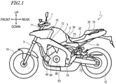
FIG. 1 is a left side view schematically showing a motorcycle 1 according to an embodiment of the present teaching. -
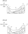
FIG. 2A is a side view showing the neighborhood of aseat 20 being in a high-position state. -
FIG. 2B is a side view showing the neighborhood of theseat 20 being in a low-position state. -
FIG. 3 is a cross-sectional view showing theseat 20. -
FIG. 4 is a perspective view showing a state where theseat 20, aspacer member 30, and atank cover member 4 are removed. -
FIG. 5 is a top view showing a state where theseat 20, atandem seat 26, and thespacer member 30 are removed. -
FIG. 6 is a top view showing a state where theseat 20 and thetandem seat 26 are removed. -
FIG. 7 is a perspective view showing the neighborhood of aseat lock bracket 78, with theseat 20 and thetandem seat 26 removed. -
FIG. 8A is a plan view showing thespacer member 30 from the rear direction. -
FIG. 8B is a side view showing thespacer member 30 from the left direction. -
FIG. 8C is a plan view showing thespacer member 30 from the front direction. -
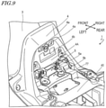
FIG. 9 is a perspective view showing the neighborhood of thetank cover member 4 before thespacer member 30 is attached. -
FIG. 10 is a perspective view showing the neighborhood of thetank cover member 4 after thespacer member 30 has been attached. -
FIG. 11 is a cross-sectional view showing thespacer member 30 having been disposed between thetank cover member 4 and theseat 20. - Hereinafter, embodiments of the present teaching will be described with reference to the drawings.
- With reference to
FIG. 1 , a motorcycle 1 according to an embodiment of the present teaching will be described.FIG. 1 is a left side view schematically showing the motorcycle 1. The motorcycle 1 shown inFIG. 1 is an on-road type motorcycle. Note that motorcycles according to embodiments of the present teaching are not limited to on-road type motorcycles. Motorcycles according to embodiments of the present teaching may be motorcycles of any other type, such as a moped type, an off-road type, or a scooter type. - In the following description, "front", "rear", "right", and "left" respectively mean the front, rear, right, and left as viewed from a rider on the motorcycle 1. Herein, "up/above" and "down/below" respectively refer to the up/above direction and the down/below direction when the motorcycle 1 is stopped on the horizontal plane.
- As shown in
FIG. 1 , the motorcycle 1 includes afuel tank 3, a main seat (which may simply be referred to as "the seat" hereinbelow) on which a rider sits, atandem seat 26 disposed rearward of themain seat 20, an engine 80 (which is an internal combustion engine), and abody frame 70 supporting these elements. - The
body frame 70 includes ahead pipe 71, amain frame 72, and a pair ofrear arms 73. A steering shaft (not shown) is supported by thehead pipe 71, with a handle bar 7 being provided at an upper portion of the steering shaft.Front forks 9 are provided at a lower portion of the steering shaft. Afront wheel 10 is supported at lower end portions of thefront forks 9 so as to be capable of rotating. - The
main frame 72 extends in an obliquely lower rear direction from thehead pipe 71. Themain frame 72 is linked to both of the pair ofrear arms 73 via apivot axis 74. Arear wheel 12 is supported at rear end portions of the pair ofrear arms 73 so as to be capable of rotating. - The
body frame 70 further includes: aseat frame 75 extending in an obliquely upper rear direction from an intermediate portion of themain frame 72; and a pair ofbackstays 76 extending in an obliquely upper rear direction from themain frame 72, rearward of theseat frame 75. - The
seat frame 75 is located below themain seat 20 and thetandem seat 26, so as to support themain seat 20 and thetandem seat 26. Theseat frame 75 includes a leftseat frame member 75a located on the left side of the vehicle and a rightseat frame member 75b located on the right side of the vehicle (seeFIG. 5 ). Theseat frame 75 and the pair ofbackstays 76 are connected to each other, rearward of themain frame 72. Agrab bar 79 is attached to theseat frame 75. - The
engine 80 is located below themain frame 72. Theengine 80 is supported by themain frame 72 in a manner not capable of swinging. Theengine 80 includes acrankcase 82, acylinder block 84 extending in an obliquely upper front direction from thecrankcase 82, acylinder head 86 connected to an upper portion of thecylinder block 84, and a cylinder head cover (not shown) connected to an upper portion of thecylinder head 86. - The
seat 20 is disposed rearward of thehead pipe 71. Thefuel tank 3 is located rearward of thehead pipe 71 and frontward of theseat 20. In other words, thefuel tank 3 is disposed between thehead pipe 71 and theseat 20. In the present embodiment, atank cover member 4 is provided between thefuel tank 3 and theseat 20. Thetank cover member 4 includes a portion covering a rear end portion of thefuel tank 3. Thetank cover member 4 is located rearward of thehead pipe 71 and frontward of theseat 20. In the present specification, any component element that is located immediately in front of theseat 20 may be referred to as an "ahead-of-seat element". In the present embodiment, thetank cover member 4 is an "ahead-of-seat element". In the case where thetank cover member 4 is not provided, thefuel tank 3 can be regarded as an "ahead-of-seat element". - The motorcycle 1 includes a seat height adjustment mechanism that is capable of adjusting the height of the
seat 20 in two steps. Therefore, the height of theseat 20 can be set to either a certain height (hereinafter referred to as a "first height") or another height that is lower than the first height (hereinafter referred to as the "second height"). In the present specification, the state where theseat 20 is at the first height is referred to as a "high-position state", whereas the state where theseat 20 is at the second height is referred to as a "low-position state". Although a configuration is illustrated herein in which the seat height adjustment mechanism is able to adjust the height of theseat 20 in two steps, the seat height adjustment mechanism may be able to adjust the height of theseat 20 in three or more steps. -
FIG. 2A is a side view showing the neighborhood of theseat 20 being in the high-position state. As shown inFIG. 2A , substantially no interspace exists between theseat 20 in the high-position state and the tank cover member (ahead-of-seat element) 4. -
FIG. 2B is a side view showing the neighborhood of theseat 20 being in the low-position state. As shown inFIG. 2B , the motorcycle 1 further includes aspacer member 30 that is disposed between theseat 20 in the low-position state (i.e., at the second height) and thetank cover member 4. Thespacer member 30 fills the interspace between theseat 20 and thetank cover member 4. - Hereinafter, the configuration of the seat height adjustment mechanism and the
spacer member 30 will be described in more detail. In the present embodiment, the seat height adjustment mechanism includes a tank bracket 5 (seeFIG. 4 ), a first supporting member 40 (seeFIG. 4 ), and a pair of second supporting members 50 (FIG. 7 ) to be described below. -
FIG. 3 is a cross-sectional view of theseat 20. As shown inFIG. 3 , theseat 20 includes: abottom plate 21 located at a bottom face of theseat 20; cushioning 22 supported by thebottom plate 21; andouter material 23 covering thecushioning 22. Thebottom plate 21 includes aprotrusion 21a that extends frontward. Although not shown herein, a plurality of load-receiving members to receive the load from theseat 20 are attached to both sides of thebottom plate 21. The load-receiving members may be made of rubber, for example. -
FIG. 4 is a perspective view showing a state where theseat 20, thespacer member 30, and thetank cover member 4 are removed.FIG. 5 is a top view showing a state where theseat 20, thetandem seat 26, and thespacer member 30 are removed. As shown inFIG. 4 andFIG. 5 , across member 77 is attached to theseat frame 75, near thefuel tank 3. Thecross member 77 bridges across the leftseat frame member 75a and the rightseat frame member 75b. - The
tank bracket 5 is attached to thefuel tank 3 and thecross member 77. As shown inFIG. 4 , thetank bracket 5 has a plurality ofinsertion holes protrusion 21a of thebottom plate 21 can be inserted. The plurality ofinsertion holes first insertion hole 5a and asecond insertion hole 5b that is formed at a lower position than is thefirst insertion hole 5a. Theprotrusion 21a of thebottom plate 21 is inserted in thefirst insertion hole 5a when theseat 20 is in the high-position state, and when theseat 20 is in the low-position state is inserted in thesecond insertion hole 5b. - The first supporting
member 40 is attached to thecross member 77 and theseat frame 75. The first supportingmember 40 may be made of a resin material, for example. The first supportingmember 40 has a substantially H shape in a plan view, and includes a pair offront extensions 41 and a pair ofrear extensions 42. - Each of the pair of
front extensions 41 has a high-position supporting surface 41a and a low-position supporting surface 41b that is located at a lower position than is the high-position supporting surface 41a. The low-position supporting surface 41b is located rearward of the high-position supporting surface 41a. In other words, the high-position supporting surface 41a and the low-position supporting surface 41b are arranged along the front-rear direction. - Each of the pair of
rear extensions 42 includes a high-position supporting surface 42a and a low-position supporting surface 42b that is located at a lower position than is the high-position supporting surface 42a. The low-position supporting surface 42b is located rearward of the high-position supporting surface 42a. In other words, the high-position supporting surface 42a and the low-position supporting surface 42b are arranged along the front-rear direction. - Note that the mounting position of the first supporting
member 40 differs depending on whether theseat 20 is in the high-position state or the low-position state.FIG. 4 andFIG. 5 show the first supportingmember 40 being attached to a mounting position for the low-position state.FIG. 6 shows the first supportingmember 40 being attached to a mounting position for the high-position state. As shown inFIG. 6 , when theseat 20 is in the high-position state, the first supportingmember 40 is attached more rearward than when theseat 20 is in the low-position state. - As shown in
FIG. 5 andFIG. 6 , aseat lock bracket 78 is attached to theseat frame 75, rearward of the first supportingmember 40. Theseat lock bracket 78 is located near a rear end portion of theseat 20.FIG. 7 is a perspective view showing the neighborhood of theseat lock bracket 78, with theseat 20 and thetandem seat 26 removed. On a lower face of theseat lock bracket 78, a main seat lock mechanism for securing theseat 20 to theseat frame 75 in a detachable manner and a tandem seat lock mechanism for securing thetandem seat 26 to theseat frame 75 in a detachable manner are provided. - A pair of second supporting
members 50 are disposed on both sides of theseat lock bracket 78. The pair of second supportingmembers 50 may be made of a resin material, for example. The pair of second supportingmembers 50 are attached to theseat frame 75, each extending along the front-rear direction. Each second supportingmember 50 includes a high-position supporting surface 50a and a low-position supporting surface 50b that is located at a lower position than is the high-position supporting surface 50a. The low-position supporting surface 50b is located rearward of the high-position supporting surface 50a. In other words, the high-position supporting surface 50a and the low-position supporting surface 50b are arranged along the front-rear direction. - As has already been described, a plurality of load-receiving members are attached to the
bottom plate 21 of theseat 20, so as to protrude downward from thebottom plate 21. These load-receiving members are supported by the first supportingmember 40 and the pair of second supportingmembers 50. Specifically, when theseat 20 is in the high-position state, the plurality of load-receiving members are supported by the high-position supporting surfaces seat 20 is in the low-position state, the plurality of load-receiving members are supported by the low-position supporting surfaces - As described above, in the present embodiment, the
tank bracket 5, the first supportingmember 40, and the pair of second supportingmembers 50 together function as a seat height adjustment mechanism, thus allowing the height of theseat 20 to be adjusted. Note that the specific configuration of the seat height adjustment mechanism is not limited to what is exemplified herein, and various configurations that allow the height of theseat 20 to be adjusted in two or more steps may be used. -
FIG. 8A, FIG. 8B andFIG. 8C are a plan view from the rear direction, a side view from the left direction, and a plan view from the front direction, respectively, of thespacer member 30.FIG. 9 is a perspective view showing the neighborhood of thetank cover member 4 before thespacer member 30 is attached.FIG. 10 is a perspective view showing the neighborhood of thetank cover member 4 after thespacer member 30 has been attached.FIG. 11 is a cross-sectional view showing thespacer member 30 having been disposed between thetank cover member 4 and theseat 20. - As shown in
FIG. 8A, FIG. 8B andFIG. 8C , thespacer member 30 includes abody section 31 and an insertion-hole closing section 32. In the present embodiment, thespacer member 30 is made of rubber. - The
body section 31 is a portion that fills the interspace between theseat 20 and the tank cover member 4 (ahead-of-seat element)(seeFIG. 11 ). Thebody section 31 has a flattened shape extending along the up-down direction and the right-left direction. As shown inFIG. 8B , thebody section 31 increases in thickness (i.e., length along the front-rear direction of the vehicle) in the upward direction from a lower end thereof. - The insertion-
hole closing section 32 is a portion which extends downward from thebody section 31 so as to close thefirst insertion hole 5a of the tank bracket 5 (seeFIGS. 10 and11 ). The insertion-hole closing section 32 includes: a protrudingportion 32a that protrudes frontward to engage with thefirst insertion hole 5a; and a connectingportion 32b that interconnects between the protrudingportion 32a and thebody section 31. - As shown in
FIG. 9 , thetank cover member 4 includes anattachment section 4A, to which thespacer member 30 is to be attached. Theattachment section 4 has a flattened shape extending along the up-down direction and the right-left direction. Theattachment section 4A has two apertures (throughholes) 4a formed in positions opposing thespacer member 30 and arecess 4b. - As shown in
FIG. 8B andFIG. 8C , thespacer member 30 further includes twofirst tabs 33, analignment section 34, and asecond tab 35. - The two
first tabs 33 are provided on a front face of thebody section 31, so as to lock into the twoapertures 4a of thetank cover member 4. Thealignment section 34 is provided on the front face of thebody section 31, and is located below thefirst tabs 33. In the example shown, thealignment section 34 is a protruding portion that protrudes frontward from the front face of thebody section 31, and as it engages with therecess 4b of thetank cover member 4, causes thespacer member 30 to be aligned with thetank cover member 4. Thesecond tab 35 is provided at a lower end of thebody section 31, so as to lock to a lower end of theattachment section 4A. - As shown in
FIG. 11 , anupper face 30t of thespacer member 30 is located at a position lower than an imaginary plane (indicated by dotted line DL inFIG. 11 ) connecting between anupper face 4t of thetank cover member 4 and anupper face 20t of theseat 20. Theseat 20 overlaps a portion of thespacer member 30 in a side view of the vehicle. - As described above, the motorcycle 1 according to an embodiment of the present teaching includes the
spacer member 30, which is located between theseat 20 being in the low-position state and the tank cover member 4 (ahead-of-seat element). Therefore, thespacer member 30 fills the interspace between theseat 20 and thetank cover member 4, thus promoting aesthetics and restraining intrusion of water and foreign objects. Thus, according to an embodiment of the present teaching, in a straddled vehicle having a seat height adjustment mechanism, it is possible to suitably restrain an interspace from emerging frontward of theseat 20. - As in the present embodiment, when the
spacer member 30 includes the insertion-hole closing section 32 to close thefirst insertion hole 5a of thetank bracket 5, an incorrect placement of the seat 20 (i.e., inserting theprotrusion 21a of thebottom plate 21 into thefirst insertion hole 5a) can be restrained. - When the
spacer member 30 includes the tabs (first tabs) 33 to lock to theapertures 4a of the tank cover member 4 (ahead-of-seat element), thespacer member 30 can be attached to thetank cover member 4 in a suitable manner. Note that the number offirst tabs 33 is not limited to two as illustrated above, but may be one or greater. - When the
spacer member 30 includes thealignment section 34, alignment of thespacer member 30 with respect to the tank cover member 4 (ahead-of-seat element) is facilitated. - The
upper face 30t of thespacer member 30 is preferably located at a position lower than an imaginary plane connecting between theupper face 4t of the tank cover member 4 (ahead-of-seat element) and theupper face 20t of theseat 20. With such a design, even if thespacer member 30 becomes somewhat larger due to manufacturing variations, theupper face 30t of thespacer member 30 is restrained from becoming higher than the aforementioned imaginary plane, whereby a decrease in aesthetics is restrained. - When the
spacer member 30 includes a portion that increases in thickness in the upward direction from a lower end thereof, it is easier to adapt the shape of thespacer member 30 to the interspace between theseat 20 being in the low-position state (i.e., at the second height) and thetank cover member 4, whereby thespacer member 30 can be reduced in weight. - When the
seat 20 overlaps a portion of thespacer member 30 in a side view of the vehicle, an interspace can be prevented from emerging between theseat 20 and thespacer member 30 in a side view of the vehicle, whereby aesthetics can be further promoted. - As the material of the
spacer member 30, rubber can be suitably used. However, the material of thespacer member 30 is not limited to rubber. For example, thespacer member 30 may be made of a resin material. When thespacer member 30 is made of a resin material, thespacer member 30 may have a different shape as compared to when it is made of rubber. For example, a portion of thebody section 31 that is not exposed to the outside may be omitted (thinned out) as appropriate. - Although the present embodiment illustrates an example where the
tank cover member 4 is the ahead-of-seat element, thetank cover member 4 may be omitted; in other words, thefuel tank 3 may be the ahead-of-seat element. In the case where thefuel tank 3 is the ahead-of-seat element, thespacer member 30 is to be attached to thefuel tank 3. In the case where thetank cover member 4 is provided (i.e., the ahead-of-seat element is the tank cover member 4), there is an advantage of being able to simplify the shape of thefuel tank 3. - Although the motorcycle 1 has been exemplified as a straddled vehicle, the straddled vehicle is meant to be any automotive vehicle on which a rider straddles and rides, without being limited to motorcycles. The straddled vehicle may be a three-wheeled motorcycle (LMW) of a type whose direction of travel is changed as its body is tilted, or an ATV (All Terrain Vehicle) such as a buggy.
- As described above, a straddled vehicle according to an embodiment of the present teaching includes: a
body frame 70 including ahead pipe 71; aseat 20 on which a rider sits, theseat 20 being disposed rearward of thehead pipe 71; an ahead-of-seat element located rearward of thehead pipe 71 and frontward of theseat 20; and a seat height adjustment mechanism capable of adjusting height of theseat 20 in at least two steps. When theseat 20 is at a first height, substantially no interspace exists between theseat 20 and the ahead-of-seat element; and the straddled vehicle further comprises aspacer member 30 to be disposed between the ahead-of-seat element and theseat 20 being at a second height which is lower than the first height, thespacer member 30 filling an interspace between the ahead-of-seat element and theseat 20 being at the second height. - A straddled vehicle according to an embodiment of the present teaching includes the
spacer member 30 that is disposed between theseat 20 at a relatively low height (second height) and a ahead-of-seat element. Therefore, thespacer member 30 fills the interspace between theseat 20 and the ahead-of-seat element, thus promoting aesthetics and restraining intrusion of water and foreign objects. - In one embodiment, the
seat 20 includes abottom plate 21 located at a bottom face of theseat 20; thebottom plate 21 includes aprotrusion 21a that extends frontward; the seat height adjustment mechanism includes abracket 5 having a plurality ofinsertion holes protrusion 21a of thebottom plate 21 is insertable; the plurality ofinsertion holes first insertion hole 5a and asecond insertion hole 5b that is formed at a lower position than is thefirst insertion hole 5a; and thespacer member 30 includes: abody section 31 which fills the interspace between the ahead-of-seat element and theseat 20 being at the second height; and an insertion-hole closing section 32 extending downward from thebody section 31 to close thefirst insertion hole 5a. - When the
spacer member 30 includes the insertion-hole closing section 32 to close an insertion hole (first insertion hole 5a) that is at a relatively high position of thebracket 5, an incorrect placement of theseat 20 can be restrained. - In one embodiment, the
spacer member 30 is made of rubber. - As the material of the
spacer member 30, rubber can be suitably used. - In one embodiment, the ahead-of-seat element has at least one aperture made in a position opposing the
spacer member 30; and thespacer member 30 includes at least onetab 33 to lock to the at least one aperture. - When the
spacer member 30 includes the tab(s) 33 to lock to the aperture(s) of the ahead-of-seat element, thespacer member 30 can be attached to the ahead-of-seat element in a suitable manner. - In one embodiment, the
spacer member 30 includes analignment section 34 that causes thespacer member 30 to be aligned with the ahead-of-seat element. - When the
spacer member 30 includes thealignment section 34, alignment of thespacer member 30 with respect to the ahead-of-seat element is facilitated. - In one embodiment, an
upper face 30t of thespacer member 30 is located at a position lower than an imaginary plane connecting between an upper face of the ahead-of-seat element and anupper face 20t of theseat 20. - The
upper face 30t of thespacer member 30 is preferably located at a position lower than an imaginary plane connecting between the upper face of the ahead-of-seat element and theupper face 20t of theseat 20. With such a design, even if thespacer member 30 becomes somewhat larger due to manufacturing variations, theupper face 30t of thespacer member 30 is restrained from becoming higher than the aforementioned imaginary plane, whereby a decrease in aesthetics is restrained. - In one embodiment, the
spacer member 30 includes a portion that increases in thickness in an upward direction from a lower end of thespacer member 30. - When the
spacer member 30 includes a portion that increases in thickness in the upward direction from a lower end thereof, it is easier to adapt the shape of thespacer member 30 to the interspace between theseat 20 being at the second height and the ahead-of-seat element, whereby thespacer member 30 can be reduced in weight. - In one embodiment, the
seat 20 overlaps a portion of thespacer member 30 in a side view of the vehicle. - When the
seat 20 overlaps a portion of thespacer member 30 in a side view of the vehicle, an interspace can be prevented from emerging between theseat 20 and thespacer member 30 in a side view of the vehicle, whereby aesthetics can be further promoted. - In one embodiment, the straddled vehicle further includes a
fuel tank 3 provided between thehead pipe 71 and theseat 20; and the ahead-of-seat element is atank cover member 4 that includes a portion covering a rear end portion of thefuel tank 3. - The ahead-of-seat element may be a
tank cover member 4 that includes a portion covering a rear end portion of thefuel tank 3, for example. By providing thetank cover member 4, the shape of thefuel tank 3 can be simplified. - In one embodiment, the ahead-of-seat element is a
fuel tank 3 provided between thehead pipe 71 and theseat 20. - The ahead-of-seat element may be the
fuel tank 3. - According to an embodiment of the present teaching, in a straddled vehicle having a seat height adjustment mechanism, it is possible to suitably restrain an interspace from emerging frontward of the seat.
Claims (10)
- A straddled vehicle comprising:a body frame (70) including a head pipe (71);a seat (20) configured for a rider to sit on, the seat (20) being disposed rearward of the head pipe (71) with regard to a front-rear direction of the vehicle;an ahead-of-seat element (3, 4) located rearward of the head pipe (71) and frontward of the seat (20) with regard to the front-rear direction of the vehicle; anda seat height adjustment mechanism (5, 40, 50) capable of adjusting height of the seat (20) in at least two steps with regard to an up-down direction of the vehicle, wherein,when the seat (20) is at a first height, substantially no interspace exists between the seat (20) and the ahead-of-seat element (3, 4); andthe straddled vehicle further comprises a spacer member (30) to be disposed between the ahead-of-seat element (3, 4) and the seat (20) being at a second height which is lower than the first height, the spacer member (30) filling an interspace between the ahead-of-seat element (3, 4) and the seat (20) being at the second height.
- The straddled vehicle of claim 1, wherein, the seat (20) includes a bottom plate (21) located at a bottom face of the seat (20);the bottom plate (21) includes a protrusion (21a) that extends frontward with regard to the front-rear direction of the vehicle;the seat height adjustment mechanism (5, 40, 50) includes a bracket having a plurality of insertion holes into which the protrusion (21a) of the bottom plate (21) is insertable;the plurality of insertion holes include a first insertion hole (5a) and a second insertion hole (5b) that is formed at a lower position than is the first insertion hole (5a) with regard to the up-down direction of the vehicle; andthe spacer member (30) includes: a body section (31) which fills the interspace between the ahead-of-seat element (3, 4) and the seat (20) being at the second height; and an insertion-hole closing section (32) extending downward from the body section (31) with regard to the up-down direction of the vehicle to close the first insertion hole (5a).
- The straddled vehicle of claim 1 or 2, wherein the spacer member (30) is made of rubber.
- The straddled vehicle of any of claims 1 to 3, wherein, the ahead-of-seat element (4) has at least one aperture (4a) made in a position opposing the spacer member (30); and
the spacer member (30) includes at least one tab (33, 35) to lock to the at least one aperture (4a). - The straddled vehicle of any of claims 1 to 4, wherein the spacer member (30) includes an alignment section (34) that causes the spacer member (30) to be aligned with the ahead-of-seat element (3, 4).
- The straddled vehicle of any of claims 1 to 5, wherein an upper face (30t) of the spacer member (30) is located at a position lower than an imaginary plane connecting between an upper face (4t) of the ahead-of-seat element (4) and an upper face (20t) of the seat (20) with regard to the up-down direction of the vehicle.
- The straddled vehicle of any of claims 1 to 6, wherein the spacer member (30) includes a portion that increases in thickness in an upward direction from a lower end of the spacer member (30) with regard to the up-down direction of the vehicle.
- The straddled vehicle of any of claims 1 to 7, wherein the seat (20) overlaps a portion of the spacer member (30) in a side view of the vehicle.
- The straddled vehicle of any of claims 1 to 8, further comprising a fuel tank (3) provided between the head pipe (71) and the seat (20); and
the ahead-of-seat element is a tank cover member (4) that includes a portion covering a rear end portion of the fuel tank (3). - The straddled vehicle of any of claims 1 to 8, wherein the ahead-of-seat element is a fuel tank (3) provided between the head pipe (71) and the seat (20).
Applications Claiming Priority (1)
| Application Number | Priority Date | Filing Date | Title |
|---|---|---|---|
| JP2020156923A JP2022050799A (en) | 2020-09-18 | 2020-09-18 | Saddle-riding type vehicle |
Publications (2)
| Publication Number | Publication Date |
|---|---|
| EP3971068A1 true EP3971068A1 (en) | 2022-03-23 |
| EP3971068B1 EP3971068B1 (en) | 2025-03-12 |
Family
ID=77431206
Family Applications (1)
| Application Number | Title | Priority Date | Filing Date |
|---|---|---|---|
| EP21192375.0A Active EP3971068B1 (en) | 2020-09-18 | 2021-08-20 | Straddled vehicle |
Country Status (2)
| Country | Link |
|---|---|
| EP (1) | EP3971068B1 (en) |
| JP (1) | JP2022050799A (en) |
Cited By (1)
| Publication number | Priority date | Publication date | Assignee | Title |
|---|---|---|---|---|
| CN117799729A (en) * | 2024-01-08 | 2024-04-02 | 重庆宗申创新技术研究院有限公司 | Adjustable seat and motorcycle |
Families Citing this family (1)
| Publication number | Priority date | Publication date | Assignee | Title |
|---|---|---|---|---|
| CN118871566A (en) | 2022-03-25 | 2024-10-29 | 麒麟控股株式会社 | Method for producing lactose difucotetraose (LDFT) |
Citations (3)
| Publication number | Priority date | Publication date | Assignee | Title |
|---|---|---|---|---|
| EP0751062A2 (en) * | 1995-06-27 | 1997-01-02 | Bayerische Motoren Werke Aktiengesellschaft, Patentabteilung AJ-3 | Height adjustable seat for a motorbike |
| EP1754657A2 (en) * | 2005-08-19 | 2007-02-21 | Yamaha Hatsudoki Kabushiki Kaisha | Seat height adjusting device for motorcycle |
| US20160214677A1 (en) * | 2015-01-23 | 2016-07-28 | Honda Motor Co., Ltd. | Storage part structure of saddle-ride-type vehicle |
-
2020
- 2020-09-18 JP JP2020156923A patent/JP2022050799A/en active Pending
-
2021
- 2021-08-20 EP EP21192375.0A patent/EP3971068B1/en active Active
Patent Citations (4)
| Publication number | Priority date | Publication date | Assignee | Title |
|---|---|---|---|---|
| EP0751062A2 (en) * | 1995-06-27 | 1997-01-02 | Bayerische Motoren Werke Aktiengesellschaft, Patentabteilung AJ-3 | Height adjustable seat for a motorbike |
| EP1754657A2 (en) * | 2005-08-19 | 2007-02-21 | Yamaha Hatsudoki Kabushiki Kaisha | Seat height adjusting device for motorcycle |
| JP2007050822A (en) | 2005-08-19 | 2007-03-01 | Yamaha Motor Co Ltd | Motorcycle seat height changing device and motorcycle |
| US20160214677A1 (en) * | 2015-01-23 | 2016-07-28 | Honda Motor Co., Ltd. | Storage part structure of saddle-ride-type vehicle |
Cited By (1)
| Publication number | Priority date | Publication date | Assignee | Title |
|---|---|---|---|---|
| CN117799729A (en) * | 2024-01-08 | 2024-04-02 | 重庆宗申创新技术研究院有限公司 | Adjustable seat and motorcycle |
Also Published As
| Publication number | Publication date |
|---|---|
| JP2022050799A (en) | 2022-03-31 |
| EP3971068B1 (en) | 2025-03-12 |
Similar Documents
| Publication | Publication Date | Title |
|---|---|---|
| JP6708687B2 (en) | Motorcycle seat frame | |
| EP3971068B1 (en) | Straddled vehicle | |
| US9669736B2 (en) | Saddle-riding type vehicle | |
| JP2004123092A (en) | Body cover structure of saddle type vehicle | |
| US11267525B2 (en) | Saddle riding vehicle | |
| EP2711273A1 (en) | Saddle riding type vehicle | |
| EP2955088B1 (en) | Straddle-type vehicle | |
| EP2055621B1 (en) | Vehicle having an article storing structure | |
| JP2007091140A (en) | Storage structure of saddle-ride type vehicle | |
| EP2679476B1 (en) | Motorcycle | |
| EP1783039B1 (en) | Motorcycle having a seat structure | |
| US9428238B2 (en) | Body frame structure for saddle type vehicle | |
| JP7177800B2 (en) | Step mounting structure | |
| JP4676281B2 (en) | Vehicle flap | |
| EP2246244B1 (en) | Two-wheeled motor vehicle | |
| US20170282985A1 (en) | Stand support structure of saddle riding vehicle | |
| EP3971067B1 (en) | Straddled vehicle seat lock | |
| JP6861665B2 (en) | Saddle-riding vehicle | |
| JP4574381B2 (en) | Step structure for motorcycle driver | |
| JP4322619B2 (en) | Body frame structure for saddle-ride type vehicles | |
| EP3971069B1 (en) | Straddled vehicle and manufacturing method for manufacturing straddled vehicle | |
| JP6290759B2 (en) | Center stand structure for saddle riding type vehicles | |
| JP2010058731A (en) | Frame of saddle-riding type vehicle and saddle-riding type vehicle equipped with the same | |
| JP6966986B2 (en) | Saddle-type vehicle | |
| EP3305641B1 (en) | Straddled vehicle |
Legal Events
| Date | Code | Title | Description |
|---|---|---|---|
| PUAI | Public reference made under article 153(3) epc to a published international application that has entered the european phase |
Free format text: ORIGINAL CODE: 0009012 |
|
| STAA | Information on the status of an ep patent application or granted ep patent |
Free format text: STATUS: REQUEST FOR EXAMINATION WAS MADE |
|
| 17P | Request for examination filed |
Effective date: 20210820 |
|
| AK | Designated contracting states |
Kind code of ref document: A1 Designated state(s): AL AT BE BG CH CY CZ DE DK EE ES FI FR GB GR HR HU IE IS IT LI LT LU LV MC MK MT NL NO PL PT RO RS SE SI SK SM TR |
|
| RBV | Designated contracting states (corrected) |
Designated state(s): AL AT BE BG CH CY CZ DE DK EE ES FI FR GB GR HR HU IE IS IT LI LT LU LV MC MK MT NL NO PL PT RO RS SE SI SK SM TR |
|
| STAA | Information on the status of an ep patent application or granted ep patent |
Free format text: STATUS: EXAMINATION IS IN PROGRESS |
|
| 17Q | First examination report despatched |
Effective date: 20221222 |
|
| P01 | Opt-out of the competence of the unified patent court (upc) registered |
Effective date: 20230527 |
|
| GRAP | Despatch of communication of intention to grant a patent |
Free format text: ORIGINAL CODE: EPIDOSNIGR1 |
|
| STAA | Information on the status of an ep patent application or granted ep patent |
Free format text: STATUS: GRANT OF PATENT IS INTENDED |
|
| INTG | Intention to grant announced |
Effective date: 20241220 |
|
| GRAS | Grant fee paid |
Free format text: ORIGINAL CODE: EPIDOSNIGR3 |
|
| GRAA | (expected) grant |
Free format text: ORIGINAL CODE: 0009210 |
|
| STAA | Information on the status of an ep patent application or granted ep patent |
Free format text: STATUS: THE PATENT HAS BEEN GRANTED |
|
| AK | Designated contracting states |
Kind code of ref document: B1 Designated state(s): AL AT BE BG CH CY CZ DE DK EE ES FI FR GB GR HR HU IE IS IT LI LT LU LV MC MK MT NL NO PL PT RO RS SE SI SK SM TR |
|
| REG | Reference to a national code |
Ref country code: GB Ref legal event code: FG4D |
|
| REG | Reference to a national code |
Ref country code: CH Ref legal event code: EP |
|
| REG | Reference to a national code |
Ref country code: DE Ref legal event code: R096 Ref document number: 602021027418 Country of ref document: DE |
|
| REG | Reference to a national code |
Ref country code: IE Ref legal event code: FG4D |
|
| PG25 | Lapsed in a contracting state [announced via postgrant information from national office to epo] |
Ref country code: RS Free format text: LAPSE BECAUSE OF FAILURE TO SUBMIT A TRANSLATION OF THE DESCRIPTION OR TO PAY THE FEE WITHIN THE PRESCRIBED TIME-LIMIT Effective date: 20250612 |
|
| PG25 | Lapsed in a contracting state [announced via postgrant information from national office to epo] |
Ref country code: FI Free format text: LAPSE BECAUSE OF FAILURE TO SUBMIT A TRANSLATION OF THE DESCRIPTION OR TO PAY THE FEE WITHIN THE PRESCRIBED TIME-LIMIT Effective date: 20250312 |
|
| PG25 | Lapsed in a contracting state [announced via postgrant information from national office to epo] |
Ref country code: ES Free format text: LAPSE BECAUSE OF FAILURE TO SUBMIT A TRANSLATION OF THE DESCRIPTION OR TO PAY THE FEE WITHIN THE PRESCRIBED TIME-LIMIT Effective date: 20250312 |
|
| REG | Reference to a national code |
Ref country code: LT Ref legal event code: MG9D |
|
| PG25 | Lapsed in a contracting state [announced via postgrant information from national office to epo] |
Ref country code: NO Free format text: LAPSE BECAUSE OF FAILURE TO SUBMIT A TRANSLATION OF THE DESCRIPTION OR TO PAY THE FEE WITHIN THE PRESCRIBED TIME-LIMIT Effective date: 20250612 |
|
| PG25 | Lapsed in a contracting state [announced via postgrant information from national office to epo] |
Ref country code: HR Free format text: LAPSE BECAUSE OF FAILURE TO SUBMIT A TRANSLATION OF THE DESCRIPTION OR TO PAY THE FEE WITHIN THE PRESCRIBED TIME-LIMIT Effective date: 20250312 |
|
| REG | Reference to a national code |
Ref country code: NL Ref legal event code: MP Effective date: 20250312 |
|
| PG25 | Lapsed in a contracting state [announced via postgrant information from national office to epo] |
Ref country code: LV Free format text: LAPSE BECAUSE OF FAILURE TO SUBMIT A TRANSLATION OF THE DESCRIPTION OR TO PAY THE FEE WITHIN THE PRESCRIBED TIME-LIMIT Effective date: 20250312 |
|
| PG25 | Lapsed in a contracting state [announced via postgrant information from national office to epo] |
Ref country code: BG Free format text: LAPSE BECAUSE OF FAILURE TO SUBMIT A TRANSLATION OF THE DESCRIPTION OR TO PAY THE FEE WITHIN THE PRESCRIBED TIME-LIMIT Effective date: 20250312 Ref country code: GR Free format text: LAPSE BECAUSE OF FAILURE TO SUBMIT A TRANSLATION OF THE DESCRIPTION OR TO PAY THE FEE WITHIN THE PRESCRIBED TIME-LIMIT Effective date: 20250613 |
|
| REG | Reference to a national code |
Ref country code: AT Ref legal event code: MK05 Ref document number: 1774822 Country of ref document: AT Kind code of ref document: T Effective date: 20250312 |
|
| PG25 | Lapsed in a contracting state [announced via postgrant information from national office to epo] |
Ref country code: NL Free format text: LAPSE BECAUSE OF FAILURE TO SUBMIT A TRANSLATION OF THE DESCRIPTION OR TO PAY THE FEE WITHIN THE PRESCRIBED TIME-LIMIT Effective date: 20250312 |
|
| PG25 | Lapsed in a contracting state [announced via postgrant information from national office to epo] |
Ref country code: SE Free format text: LAPSE BECAUSE OF FAILURE TO SUBMIT A TRANSLATION OF THE DESCRIPTION OR TO PAY THE FEE WITHIN THE PRESCRIBED TIME-LIMIT Effective date: 20250312 |
|
| PG25 | Lapsed in a contracting state [announced via postgrant information from national office to epo] |
Ref country code: SM Free format text: LAPSE BECAUSE OF FAILURE TO SUBMIT A TRANSLATION OF THE DESCRIPTION OR TO PAY THE FEE WITHIN THE PRESCRIBED TIME-LIMIT Effective date: 20250312 |
|
| PG25 | Lapsed in a contracting state [announced via postgrant information from national office to epo] |
Ref country code: PT Free format text: LAPSE BECAUSE OF FAILURE TO SUBMIT A TRANSLATION OF THE DESCRIPTION OR TO PAY THE FEE WITHIN THE PRESCRIBED TIME-LIMIT Effective date: 20250714 |
|
| PGFP | Annual fee paid to national office [announced via postgrant information from national office to epo] |
Ref country code: DE Payment date: 20250820 Year of fee payment: 5 |
|
| PG25 | Lapsed in a contracting state [announced via postgrant information from national office to epo] |
Ref country code: PL Free format text: LAPSE BECAUSE OF FAILURE TO SUBMIT A TRANSLATION OF THE DESCRIPTION OR TO PAY THE FEE WITHIN THE PRESCRIBED TIME-LIMIT Effective date: 20250312 |
|
| PGFP | Annual fee paid to national office [announced via postgrant information from national office to epo] |
Ref country code: IT Payment date: 20250825 Year of fee payment: 5 |
|
| PG25 | Lapsed in a contracting state [announced via postgrant information from national office to epo] |
Ref country code: AT Free format text: LAPSE BECAUSE OF FAILURE TO SUBMIT A TRANSLATION OF THE DESCRIPTION OR TO PAY THE FEE WITHIN THE PRESCRIBED TIME-LIMIT Effective date: 20250312 |
|
| PGFP | Annual fee paid to national office [announced via postgrant information from national office to epo] |
Ref country code: FR Payment date: 20250828 Year of fee payment: 5 |
|
| PG25 | Lapsed in a contracting state [announced via postgrant information from national office to epo] |
Ref country code: CZ Free format text: LAPSE BECAUSE OF FAILURE TO SUBMIT A TRANSLATION OF THE DESCRIPTION OR TO PAY THE FEE WITHIN THE PRESCRIBED TIME-LIMIT Effective date: 20250312 Ref country code: EE Free format text: LAPSE BECAUSE OF FAILURE TO SUBMIT A TRANSLATION OF THE DESCRIPTION OR TO PAY THE FEE WITHIN THE PRESCRIBED TIME-LIMIT Effective date: 20250312 |
|
| PG25 | Lapsed in a contracting state [announced via postgrant information from national office to epo] |
Ref country code: RO Free format text: LAPSE BECAUSE OF FAILURE TO SUBMIT A TRANSLATION OF THE DESCRIPTION OR TO PAY THE FEE WITHIN THE PRESCRIBED TIME-LIMIT Effective date: 20250312 |
|
| PG25 | Lapsed in a contracting state [announced via postgrant information from national office to epo] |
Ref country code: SK Free format text: LAPSE BECAUSE OF FAILURE TO SUBMIT A TRANSLATION OF THE DESCRIPTION OR TO PAY THE FEE WITHIN THE PRESCRIBED TIME-LIMIT Effective date: 20250312 |
|
| PG25 | Lapsed in a contracting state [announced via postgrant information from national office to epo] |
Ref country code: IS Free format text: LAPSE BECAUSE OF FAILURE TO SUBMIT A TRANSLATION OF THE DESCRIPTION OR TO PAY THE FEE WITHIN THE PRESCRIBED TIME-LIMIT Effective date: 20250712 |
|
| REG | Reference to a national code |
Ref country code: DE Ref legal event code: R097 Ref document number: 602021027418 Country of ref document: DE |
|
| PG25 | Lapsed in a contracting state [announced via postgrant information from national office to epo] |
Ref country code: DK Free format text: LAPSE BECAUSE OF FAILURE TO SUBMIT A TRANSLATION OF THE DESCRIPTION OR TO PAY THE FEE WITHIN THE PRESCRIBED TIME-LIMIT Effective date: 20250312 |
|
| PLBE | No opposition filed within time limit |
Free format text: ORIGINAL CODE: 0009261 |
|
| STAA | Information on the status of an ep patent application or granted ep patent |
Free format text: STATUS: NO OPPOSITION FILED WITHIN TIME LIMIT |
|
| REG | Reference to a national code |
Ref country code: CH Ref legal event code: L10 Free format text: ST27 STATUS EVENT CODE: U-0-0-L10-L00 (AS PROVIDED BY THE NATIONAL OFFICE) Effective date: 20260121 |
|
| 26N | No opposition filed |
Effective date: 20251215 |
|
| REG | Reference to a national code |
Ref country code: CH Ref legal event code: H13 Free format text: ST27 STATUS EVENT CODE: U-0-0-H10-H13 (AS PROVIDED BY THE NATIONAL OFFICE) Effective date: 20260324 |
|
| PG25 | Lapsed in a contracting state [announced via postgrant information from national office to epo] |
Ref country code: MC Free format text: LAPSE BECAUSE OF FAILURE TO SUBMIT A TRANSLATION OF THE DESCRIPTION OR TO PAY THE FEE WITHIN THE PRESCRIBED TIME-LIMIT Effective date: 20250312 |
|
| PG25 | Lapsed in a contracting state [announced via postgrant information from national office to epo] |
Ref country code: LU Free format text: LAPSE BECAUSE OF NON-PAYMENT OF DUE FEES Effective date: 20250820 |
|
| PG25 | Lapsed in a contracting state [announced via postgrant information from national office to epo] |
Ref country code: CH Free format text: LAPSE BECAUSE OF NON-PAYMENT OF DUE FEES Effective date: 20250831 |
|
| GBPC | Gb: european patent ceased through non-payment of renewal fee |
Effective date: 20250820 |