EP3971063A1 - A track deviation sensing mechanism - Google Patents
A track deviation sensing mechanism Download PDFInfo
- Publication number
- EP3971063A1 EP3971063A1 EP20196967.2A EP20196967A EP3971063A1 EP 3971063 A1 EP3971063 A1 EP 3971063A1 EP 20196967 A EP20196967 A EP 20196967A EP 3971063 A1 EP3971063 A1 EP 3971063A1
- Authority
- EP
- European Patent Office
- Prior art keywords
- ring
- sensing mechanism
- track deviation
- axial opening
- sleeve
- Prior art date
- Legal status (The legal status is an assumption and is not a legal conclusion. Google has not performed a legal analysis and makes no representation as to the accuracy of the status listed.)
- Granted
Links
Images


Classifications
-
- B—PERFORMING OPERATIONS; TRANSPORTING
- B62—LAND VEHICLES FOR TRAVELLING OTHERWISE THAN ON RAILS
- B62D—MOTOR VEHICLES; TRAILERS
- B62D15/00—Steering not otherwise provided for
- B62D15/02—Steering position indicators ; Steering position determination; Steering aids
- B62D15/021—Determination of steering angle
- B62D15/0215—Determination of steering angle by measuring on the steering column
-
- B—PERFORMING OPERATIONS; TRANSPORTING
- B62—LAND VEHICLES FOR TRAVELLING OTHERWISE THAN ON RAILS
- B62D—MOTOR VEHICLES; TRAILERS
- B62D1/00—Steering controls, i.e. means for initiating a change of direction of the vehicle
- B62D1/02—Steering controls, i.e. means for initiating a change of direction of the vehicle vehicle-mounted
- B62D1/16—Steering columns
-
- F—MECHANICAL ENGINEERING; LIGHTING; HEATING; WEAPONS; BLASTING
- F16—ENGINEERING ELEMENTS AND UNITS; GENERAL MEASURES FOR PRODUCING AND MAINTAINING EFFECTIVE FUNCTIONING OF MACHINES OR INSTALLATIONS; THERMAL INSULATION IN GENERAL
- F16B—DEVICES FOR FASTENING OR SECURING CONSTRUCTIONAL ELEMENTS OR MACHINE PARTS TOGETHER, e.g. NAILS, BOLTS, CIRCLIPS, CLAMPS, CLIPS OR WEDGES; JOINTS OR JOINTING
- F16B2/00—Friction-grip releasable fastenings
- F16B2/20—Clips, i.e. with gripping action effected solely by the inherent resistance to deformation of the material of the fastening
- F16B2/22—Clips, i.e. with gripping action effected solely by the inherent resistance to deformation of the material of the fastening of resilient material, e.g. rubbery material
- F16B2/24—Clips, i.e. with gripping action effected solely by the inherent resistance to deformation of the material of the fastening of resilient material, e.g. rubbery material of metal
- F16B2/241—Clips, i.e. with gripping action effected solely by the inherent resistance to deformation of the material of the fastening of resilient material, e.g. rubbery material of metal of sheet metal
- F16B2/243—Clips, i.e. with gripping action effected solely by the inherent resistance to deformation of the material of the fastening of resilient material, e.g. rubbery material of metal of sheet metal internal, i.e. with spreading action
-
- F—MECHANICAL ENGINEERING; LIGHTING; HEATING; WEAPONS; BLASTING
- F16—ENGINEERING ELEMENTS AND UNITS; GENERAL MEASURES FOR PRODUCING AND MAINTAINING EFFECTIVE FUNCTIONING OF MACHINES OR INSTALLATIONS; THERMAL INSULATION IN GENERAL
- F16D—COUPLINGS FOR TRANSMITTING ROTATION; CLUTCHES; BRAKES
- F16D1/00—Couplings for rigidly connecting two coaxial shafts or other movable machine elements
- F16D1/10—Quick-acting couplings in which the parts are connected by simply bringing them together axially
-
- F—MECHANICAL ENGINEERING; LIGHTING; HEATING; WEAPONS; BLASTING
- F16—ENGINEERING ELEMENTS AND UNITS; GENERAL MEASURES FOR PRODUCING AND MAINTAINING EFFECTIVE FUNCTIONING OF MACHINES OR INSTALLATIONS; THERMAL INSULATION IN GENERAL
- F16D—COUPLINGS FOR TRANSMITTING ROTATION; CLUTCHES; BRAKES
- F16D1/00—Couplings for rigidly connecting two coaxial shafts or other movable machine elements
- F16D1/10—Quick-acting couplings in which the parts are connected by simply bringing them together axially
- F16D2001/103—Quick-acting couplings in which the parts are connected by simply bringing them together axially the torque is transmitted via splined connections
Definitions
- the present invention relates to the field detecting degree of rotation of a steering column of a vehicle.
- Vehicles are steered by changing the orientation of the wheels by rotating the steering column.
- path defining technology it is required to initially determine a defined path along which the vehicle is required to be driven.
- the path is defined based on a predefined parameter, such as, obstacles, optimized route, shortest route and the like.
- a track follow system and mechanism to ensure that the vehicle follows the defined path.
- the track follow system is required to determine the movement of the wheels which is caused by rotation of the steering column.
- the track follow system calculates any deviation in the path of the vehicle from the defined path determined by the path defining technology.
- the deviation is either communicated to the operator to manually ensure a course correction or alternatively a controller may receive the deviation to automatically ensure the course correction.
- a controller may receive the deviation to automatically ensure the course correction.
- the present invention aims to increase the service life of the sensing mechanism for a steering column while facilitating retrofitting onto a steering column.
- a track deviation sensing mechanism for a steering column comprises a sleeve, a sensor with a ring, a first part and a second part.
- the sleeve receives the steering column.
- the sleeve has an inner wall and an outer wall defining an annular opening.
- the inner wall defines a plurality of internal splines.
- the sensor has a first axial opening.
- the ring is disposed within said first axial opening.
- the ring defines a second axial opening for accommodating the sleeve.
- a key project from the ring towards the first axial opening.
- the key is integral with the ring. Alternatively, the key is discrete from the ring.
- the first part functionally disposed between the sleeve and the ring.
- the first part lockingly connected to the sleeve and the ring.
- the first part has a third axial opening.
- the first part cooperates with the sleeve by at least one of a snap fit arrangement or an interference fit arrangement.
- the first part a keyway associated with the key.
- the second part locks the sensor and the first part at a prerequisite configuration.
- the second part has a fourth axial opening.
- the first axial opening, said second axial opening, said third axial opening, said fourth axial opening and said annular opening are coaxial.
- the second part cooperates with the sensor and the first part by at least one of a snap fit arrangement or an interference fit arrangement.
- the second part cooperates with the first part by joining elements.
- the rotation of the steering column is transmitted to the ring via the first part.
- the sensor is configured to determine the degree of rotation of the ring and hence the degree of rotation of the steering column.
- the first part and said second part are made of at least one of a polymeric material, a composite material and a metal.
- Figure 1 illustrates a steering column 1 of a vehicle cooperating with a track deviation sensing mechanism 10, in accordance with the present invention, through a sleeve 12.
- Figure 2 to Figure 5 illustrates the sleeve 12 of the steering column 1, a sensor 14, a ring 16, a first part 18 and a second part 20.
- the sensor 14 has not been described in detail.
- the sensor 14 works in the same way as known sensors for detecting rotation of a steering column 1.
- the sensor 14 has a first axial opening 22.
- the sleeve 12 has an inner wall 24 and an outer wall 26.
- the inner wall 24 defines an annular opening 28 with a locking edge 30.
- the inner wall 24 has a plurality of internal splines 32.
- the steering column 1 cooperates with the internal sleeve 32 through a plurality of complementary splines 34, defined on an external wall of the steering column 1. With rotation of the steering column 1, the sleeve 12 is caused to rotate due to the splined connection between them.
- the sensor 14 includes the ring 16 which is disposed within the first annular opening 22.
- the operation of the ring 16 with respect to the sensor 14 operates in a known way. While the sensor 14 is fixed at a predetermined position and is restricted to have any rotational or axial movement, the ring 16 is free to rotate with respect to the sensor 14. However, similar to the sensor 14, the ring 16 is also restricted to have any axial movement.
- the ring 16 defines a second axial opening 36.
- the ring 16 includes one or more key 38.
- the key 38 is a projection which radially extends towards the second axial opening 36.
- the key 38 may be integral with the ring 16.
- the key 38 is discrete from the ring 16.
- the first part 18 is disposed between the sleeve 12 and the ring 16.
- the first part 18 has a third axial opening 40.
- the first part 18 has a plurality of projection 42 with a hook 44 defined at the end thereof.
- the hook 44 may be a bead or a bump.
- the plurality of projection 42 project towards the center of the third axial opening 40.
- the projection 42 snap fits onto the locking edge 30 of the sleeve 12. This creates a rigid connection between the sleeve 12 and the first part 18.
- the first part 18 is fitted between the sleeve 12 and the ring 16 by an interference fitting method.
- the first part 18, on the surface proximate to the ring 16, has a notch forming a keyway 46.
- the keyway 46 is profiled to complement the shape of the key 38 of the ring 16.
- the key 38 of the ring 16 is adjusted to seat on the keyway 46 of the first part 18.
- the first part is locked to the sleeve 12 by the projection 42 and is also locked to the ring 16 by the key 38. Additionally, the first part 18 may be snap fitted to the ring 16 by one or more snap fitting elements 39.
- the rotational movement of the steering column 1 is transmitted to the ring 16 via the sleeve 12 and the first part 18. Since, the ring 16 is freely rotatable with respect to the sensor 14, the degree of rotation of the ring 16 is equal to the degree of rotation of the steering column 1.
- the sensor 14 detects the degree of rotation of the ring 16 which corresponds to the degree of rotation of the steering column 1. Thus, on detecting the rotation of the ring 16, the sensor 14 actually detects the degree of rotation of the steering column 1. This degree of rotation of the steering column 1 may be used for providing necessary input to an operator or a controller of the vehicle.
- the second part 20 is provided to clamp the sensor 14, the first part 18 and the sleeve 12 in a prerequisite configuration.
- the first part 18 and the second part 20 are preferably made of a polymeric material.
- the first part 18 and the second part 20 are made of a composite material or a metal.
- the second part 20 snap fits onto the sensor 14 by a plurality of snap fitting members 50.
- the snap fitting arrangement 50 projects towards the center of the fourth axial opening 48.
- the snap fitting arrangement 50 snap fits onto the sensor 14.
- the second part 20 is fitted to the sensor 14 and to the first part 18 by an interference fit or a joining element not particularly shown in the Figure. This creates a rigid connection between the sensor 14 and the first part 18.
- the second part 20 prevents in rigidly connecting the sensor 14 and the first part 18. This prevents play or friction between the first part 18 and the second part 20.
- the entire assembly of the track deviation sensing mechanism 10 is restricted to be axially displaceable.
- the first axial opening 22, the second axial opening 36, the third axial opening 40, the fourth axial opening and the annular opening 28 are coaxial along the axis X.
- the second part 20 while clamping the sensor 14, encases the sleeve 12, the first part 18 and the ring 16 of the sensor 14 within the fourth axial opening 48.
- the track deviation sensing mechanism 10 helps in avoiding any play or friction between the first part 18, the second part 20 and the sensor 14 with the ring 16. Additionally, it helps in increasing service life of the track deviation sensing mechanism for a steering column 1. Further, it facilitates the track deviation sensing mechanism 10 to be retrofittable on a steering column 10. It also reduces overall weight of the track deviation sensing mechanism 10 while minimizing cost of the track deviation sensing mechanism 10.
Landscapes
- Engineering & Computer Science (AREA)
- Mechanical Engineering (AREA)
- General Engineering & Computer Science (AREA)
- Chemical & Material Sciences (AREA)
- Combustion & Propulsion (AREA)
- Transportation (AREA)
- Steering Controls (AREA)
- Length Measuring Devices With Unspecified Measuring Means (AREA)
Abstract
Description
- The present invention relates to the field detecting degree of rotation of a steering column of a vehicle.
- Vehicles are steered by changing the orientation of the wheels by rotating the steering column. With the advent of path defining technology, it is required to initially determine a defined path along which the vehicle is required to be driven. The path is defined based on a predefined parameter, such as, obstacles, optimized route, shortest route and the like. Thus, as there is a defined path, there is also a requirement to use a track follow system and mechanism to ensure that the vehicle follows the defined path. In order to maintain the vehicle along the defined path, the track follow system is required to determine the movement of the wheels which is caused by rotation of the steering column. The track follow system calculates any deviation in the path of the vehicle from the defined path determined by the path defining technology. The deviation is either communicated to the operator to manually ensure a course correction or alternatively a controller may receive the deviation to automatically ensure the course correction. Currently, there are several types of sensor arrangement which are used to detect the deviation. However, due to constant play and friction between parts of the sensor as well as mounting arrangement, there are frequent failure issues.
- Hence, there is a requirement of a sensing mechanism for detecting deviation from a defined path which minimizes the drawbacks of the prior art to avoid play between various parts of a sensing mechanism for a steering column. The present invention aims to increase the service life of the sensing mechanism for a steering column while facilitating retrofitting onto a steering column.
- The above-mentioned problem will be solved by the teachings of claim1. Further advantageous embodiments are defined by the dependent claims and the sub claims.
- Accordingly, a track deviation sensing mechanism for a steering column comprises a sleeve, a sensor with a ring, a first part and a second part. The sleeve receives the steering column. The sleeve has an inner wall and an outer wall defining an annular opening. The inner wall defines a plurality of internal splines.
- The sensor has a first axial opening. The ring is disposed within said first axial opening. The ring defines a second axial opening for accommodating the sleeve. A key project from the ring towards the first axial opening. The key is integral with the ring. Alternatively, the key is discrete from the ring.
- The first part functionally disposed between the sleeve and the ring. The first part lockingly connected to the sleeve and the ring. The first part has a third axial opening. The first part cooperates with the sleeve by at least one of a snap fit arrangement or an interference fit arrangement. The first part a keyway associated with the key.
- The second part locks the sensor and the first part at a prerequisite configuration. The second part has a fourth axial opening. The first axial opening, said second axial opening, said third axial opening, said fourth axial opening and said annular opening are coaxial. The second part cooperates with the sensor and the first part by at least one of a snap fit arrangement or an interference fit arrangement. The second part cooperates with the first part by joining elements. The rotation of the steering column is transmitted to the ring via the first part. The sensor is configured to determine the degree of rotation of the ring and hence the degree of rotation of the steering column. The first part and said second part are made of at least one of a polymeric material, a composite material and a metal.
- The drawings show two embodiment examples of the invention, described in more detail below, wherein the brief description of the drawings refers to the accompanying figures in which:
-
Figure 1 illustrates a perspective view of a track deviation sensing mechanism, in accordance with the present invention, with a steering column arrangement; -
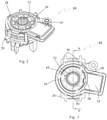
Figure 2 illustrates a perspective view of a track deviation sensing mechanism, in accordance with the present invention, without a steering column arrangement; -
Figure 3 illustrates a top view of a track deviation sensing mechanism, ofFigure 2 ; -
Figure 4 illustrates a sectional view of a track deviation sensing mechanism, ofFigure 3 , along the line A-A; and -
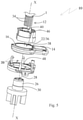
Figure 5 illustrates a exploded view of a track deviation sensing mechanism, ofFigure 2 . -
Figure 1 illustrates a steering column 1 of a vehicle cooperating with a trackdeviation sensing mechanism 10, in accordance with the present invention, through asleeve 12.Figure 2 to Figure 5 illustrates thesleeve 12 of the steering column 1, asensor 14, aring 16, afirst part 18 and asecond part 20. Thesensor 14 has not been described in detail. Thesensor 14 works in the same way as known sensors for detecting rotation of a steering column 1. Thesensor 14 has a first axial opening 22. - Referring to
Figure 2 andFigure 5 , thesleeve 12 has an inner wall 24 and anouter wall 26. The inner wall 24 defines anannular opening 28 with alocking edge 30. The inner wall 24 has a plurality ofinternal splines 32. The steering column 1 cooperates with theinternal sleeve 32 through a plurality ofcomplementary splines 34, defined on an external wall of the steering column 1. With rotation of the steering column 1, thesleeve 12 is caused to rotate due to the splined connection between them. - Referring to
Figure 2 to Figure 5 , thesensor 14 includes thering 16 which is disposed within the first annular opening 22. The operation of thering 16 with respect to thesensor 14 operates in a known way. While thesensor 14 is fixed at a predetermined position and is restricted to have any rotational or axial movement, thering 16 is free to rotate with respect to thesensor 14. However, similar to thesensor 14, thering 16 is also restricted to have any axial movement. Thering 16 defines a second axial opening 36. Thering 16 includes one ormore key 38. Thekey 38 is a projection which radially extends towards the second axial opening 36. The key 38 may be integral with thering 16. Optionally, the key 38 is discrete from thering 16. - Again, referring to
Figure 2 to Figure 5 , thefirst part 18 is disposed between thesleeve 12 and thering 16. Thefirst part 18 has a thirdaxial opening 40. Thefirst part 18 has a plurality ofprojection 42 with ahook 44 defined at the end thereof. Alternatively, thehook 44 may be a bead or a bump. The plurality ofprojection 42 project towards the center of the thirdaxial opening 40. Theprojection 42 snap fits onto the lockingedge 30 of thesleeve 12. This creates a rigid connection between thesleeve 12 and thefirst part 18. Thus, the rotational movement of the steering column 1 is transmitted to thefirst part 18 via thesleeve 12. Optionally, thefirst part 18 is fitted between thesleeve 12 and thering 16 by an interference fitting method. - The
first part 18, on the surface proximate to thering 16, has a notch forming akeyway 46. Thekeyway 46 is profiled to complement the shape of the key 38 of thering 16. The key 38 of thering 16 is adjusted to seat on thekeyway 46 of thefirst part 18. The first part is locked to thesleeve 12 by theprojection 42 and is also locked to thering 16 by the key 38. Additionally, thefirst part 18 may be snap fitted to thering 16 by one or more snapfitting elements 39. Thus, the rotational movement of the steering column 1 is transmitted to thering 16 via thesleeve 12 and thefirst part 18. Since, thering 16 is freely rotatable with respect to thesensor 14, the degree of rotation of thering 16 is equal to the degree of rotation of the steering column 1. - The
sensor 14 detects the degree of rotation of thering 16 which corresponds to the degree of rotation of the steering column 1. Thus, on detecting the rotation of thering 16, thesensor 14 actually detects the degree of rotation of the steering column 1. This degree of rotation of the steering column 1 may be used for providing necessary input to an operator or a controller of the vehicle. - The
second part 20 is provided to clamp thesensor 14, thefirst part 18 and thesleeve 12 in a prerequisite configuration. Thefirst part 18 and thesecond part 20 are preferably made of a polymeric material. Alternatively, thefirst part 18 and thesecond part 20 are made of a composite material or a metal. In accordance with an embodiment, as illustrated in theFigure 2 to Figure 5 , thesecond part 20 snap fits onto thesensor 14 by a plurality ofsnap fitting members 50. The snapfitting arrangement 50 projects towards the center of the fourthaxial opening 48. The snapfitting arrangement 50 snap fits onto thesensor 14. Optionally, thesecond part 20 is fitted to thesensor 14 and to thefirst part 18 by an interference fit or a joining element not particularly shown in the Figure. This creates a rigid connection between thesensor 14 and thefirst part 18. Thus, thesecond part 20 prevents in rigidly connecting thesensor 14 and thefirst part 18. This prevents play or friction between thefirst part 18 and thesecond part 20. The entire assembly of the trackdeviation sensing mechanism 10 is restricted to be axially displaceable. - The first axial opening 22, the second axial opening 36, the third
axial opening 40, the fourth axial opening and theannular opening 28 are coaxial along the axis X. Thesecond part 20 while clamping thesensor 14, encases thesleeve 12, thefirst part 18 and thering 16 of thesensor 14 within the fourthaxial opening 48. Thus, the trackdeviation sensing mechanism 10 helps in avoiding any play or friction between thefirst part 18, thesecond part 20 and thesensor 14 with thering 16. Additionally, it helps in increasing service life of the track deviation sensing mechanism for a steering column 1. Further, it facilitates the trackdeviation sensing mechanism 10 to be retrofittable on asteering column 10. It also reduces overall weight of the trackdeviation sensing mechanism 10 while minimizing cost of the trackdeviation sensing mechanism 10.
Claims (10)
- A track deviation sensing mechanism (10) for a steering column (1):a sleeve (12) having an inner wall (24) and an outer wall (26) defining an annular opening (28), said inner wall (24) defining a plurality of internal splines (32), said sleeve (12) receiving the steering column (1);a sensor (14) having a first axial opening (22);a ring (16) disposed within said first axial opening (22), said ring (16) defining a second axial opening (36), said second axial opening (36) accommodating said sleeve (12);a first part (18) functionally disposed between said sleeve (12) and said ring (16), said first part (18) lockingly connected to said sleeve (12) and said ring (16), said first part (18) having a third axial opening (40); anda second part (20) locking said sensor (14) and said first part (18) at a prerequisite configuration, said second part (20) having a fourth axial opening (48), said first axial opening (22), said second axial opening (36), said third axial opening (40), said fourth axial opening (48) and said annular opening (28) being coaxial.
- The track deviation sensing mechanism (10) as claimed in Claim 1, wherein said first part (18) cooperates with said sleeve (12) by at least one of a snap fit arrangement or an interference fit arrangement.
- The track deviation sensing mechanism (10) as claimed in Claim 1, wherein said second part (20) cooperates with said sensor (14) and said first part (18) by at least one of a snap fit arrangement or an interference fit arrangement.
- The track deviation sensing mechanism (10) as claimed in Claim 1, wherein said second part (20) cooperates with said first part (18) by joining elements.
- The track deviation sensing mechanism (10) as claimed in Claim 1, wherein at least one key (38) project from said ring (16).
- The track deviation sensing mechanism (10) as claimed in Claim 6, wherein said at least one key (38) is integral with said ring (16).
- The track deviation sensing mechanism (10) as claimed in Claim 6, wherein said at least one key (38) is discrete from said ring (16).
- The track deviation sensing mechanism (10) as claimed in Claim 1 and claim 6, wherein said first part (18) defines at least one keyway (46), each of said keyway (46) being associated with said at least one key (38).
- The track deviation sensing mechanism (10) as claimed in Claim 1, wherein the rotation of said steering column (1) is transmitted to said ring (16) via said first part (18), said sensor (14) being configured to determine the degree of rotation of said ring (16).
- The track deviation sensing mechanism (10) as claimed in Claim 1, wherein said first part (18) and said second part (20) are made of at least one of a polymeric material, a composite material and a metal.
Priority Applications (3)
| Application Number | Priority Date | Filing Date | Title |
|---|---|---|---|
| EP20196967.2A EP3971063B1 (en) | 2020-09-18 | 2020-09-18 | A track deviation sensing mechanism |
| BR102021010818-5A BR102021010818A2 (en) | 2020-09-18 | 2021-06-02 | LANE DEVIATION DETECTION MECHANISM |
| US17/445,626 US11713075B2 (en) | 2020-09-18 | 2021-08-23 | Track deviation sensing mechanism |
Applications Claiming Priority (1)
| Application Number | Priority Date | Filing Date | Title |
|---|---|---|---|
| EP20196967.2A EP3971063B1 (en) | 2020-09-18 | 2020-09-18 | A track deviation sensing mechanism |
Publications (2)
| Publication Number | Publication Date |
|---|---|
| EP3971063A1 true EP3971063A1 (en) | 2022-03-23 |
| EP3971063B1 EP3971063B1 (en) | 2024-08-14 |
Family
ID=72561689
Family Applications (1)
| Application Number | Title | Priority Date | Filing Date |
|---|---|---|---|
| EP20196967.2A Active EP3971063B1 (en) | 2020-09-18 | 2020-09-18 | A track deviation sensing mechanism |
Country Status (3)
| Country | Link |
|---|---|
| US (1) | US11713075B2 (en) |
| EP (1) | EP3971063B1 (en) |
| BR (1) | BR102021010818A2 (en) |
Citations (3)
| Publication number | Priority date | Publication date | Assignee | Title |
|---|---|---|---|---|
| EP1260424A2 (en) * | 2001-05-25 | 2002-11-27 | Valeo Schalter und Sensoren GmbH | Transmission unit |
| DE102008062416A1 (en) * | 2008-12-17 | 2010-07-01 | Sauer-Danfoss Aps | Angle of rotation sensor, in particular steering angle sensor for a steering unit |
| DE102017118457A1 (en) * | 2017-08-14 | 2019-02-14 | Danfoss Power Solutions Aps | Hydraulic steering arrangement |
Family Cites Families (18)
| Publication number | Priority date | Publication date | Assignee | Title |
|---|---|---|---|---|
| DE19647705C2 (en) | 1996-11-11 | 1998-10-08 | Petri Ag | Device for determining the angular position of the steering wheel in a motor vehicle |
| US5807180A (en) * | 1997-08-28 | 1998-09-15 | Dana Corporation | Constant velocity universal joint shaft and inner race combination |
| JP2008007075A (en) * | 2006-06-30 | 2008-01-17 | Yazaki Corp | Rotation connector device with built-in rudder angle sensor |
| CN101708736B (en) | 2009-12-11 | 2011-08-10 | 北汽福田汽车股份有限公司 | Steering wheel corner sensor device and automobile electronic stabilization system |
| US8390276B2 (en) * | 2010-09-27 | 2013-03-05 | Bourns Incorporated | Target magnet assembly for a sensor used with a steering gear |
| DE102011118642A1 (en) | 2011-11-15 | 2013-05-16 | Valeo Schalter Und Sensoren Gmbh | Method for connecting a sensor part with a shaft part of a motor vehicle and arrangement with a shaft part and a sensor part |
| DE102013015452A1 (en) | 2013-09-18 | 2015-03-19 | Valeo Schalter Und Sensoren Gmbh | Method for producing a magnet unit for a sensor device for detecting a measured variable characterizing a rotational state of a steering shaft of a motor vehicle, magnet unit, sensor device and motor vehicle |
| DE102014109473B4 (en) * | 2014-07-07 | 2024-01-11 | Dr. Ing. H.C. F. Porsche Aktiengesellschaft | Connection arrangement for torque transmission for use in the drive train of a motor vehicle |
| DE102015122176A1 (en) | 2015-12-18 | 2017-06-22 | Valeo Schalter Und Sensoren Gmbh | Magnet unit for a sensor device of a motor vehicle, sensor device with a magnet unit and motor vehicle with a sensor device |
| DE102016110774A1 (en) | 2016-06-13 | 2017-12-14 | Valeo Schalter Und Sensoren Gmbh | Magnet unit for a sensor device of a motor vehicle, sensor device with a magnet unit and motor vehicle with a sensor device |
| JP6683055B2 (en) * | 2016-07-27 | 2020-04-15 | 株式会社ジェイテクト | Torque detection device and electric power steering device |
| KR101888480B1 (en) | 2016-08-11 | 2018-09-20 | 이광남 | Complex Type Torque Sensor |
| DE102017118456B4 (en) * | 2017-05-23 | 2019-12-12 | Bourns, Inc. | Stator mounting in the torque sensor |
| DE102017209664A1 (en) * | 2017-06-08 | 2018-12-13 | Thyssenkrupp Ag | Steering column for a motor vehicle |
| KR102452164B1 (en) * | 2017-09-08 | 2022-10-11 | 엘지이노텍 주식회사 | Sensor assembly |
| DE102020100319A1 (en) * | 2020-01-09 | 2021-07-15 | HELLA GmbH & Co. KGaA | Angle of rotation sensor for determining an angle of rotation and / or a torque |
| US11629978B2 (en) * | 2021-02-25 | 2023-04-18 | Bcs Automotive Interface Solutions Us Llc | Absolute steering sensor assembly |
| DE102021205253B4 (en) * | 2021-05-21 | 2024-08-14 | Zf Automotive Germany Gmbh | Method for cooperative steering angle control, control unit and electromechanically assisted steering system |
-
2020
- 2020-09-18 EP EP20196967.2A patent/EP3971063B1/en active Active
-
2021
- 2021-06-02 BR BR102021010818-5A patent/BR102021010818A2/en unknown
- 2021-08-23 US US17/445,626 patent/US11713075B2/en active Active
Patent Citations (3)
| Publication number | Priority date | Publication date | Assignee | Title |
|---|---|---|---|---|
| EP1260424A2 (en) * | 2001-05-25 | 2002-11-27 | Valeo Schalter und Sensoren GmbH | Transmission unit |
| DE102008062416A1 (en) * | 2008-12-17 | 2010-07-01 | Sauer-Danfoss Aps | Angle of rotation sensor, in particular steering angle sensor for a steering unit |
| DE102017118457A1 (en) * | 2017-08-14 | 2019-02-14 | Danfoss Power Solutions Aps | Hydraulic steering arrangement |
Also Published As
| Publication number | Publication date |
|---|---|
| US11713075B2 (en) | 2023-08-01 |
| US20220089220A1 (en) | 2022-03-24 |
| EP3971063B1 (en) | 2024-08-14 |
| BR102021010818A2 (en) | 2022-07-12 |
Similar Documents
| Publication | Publication Date | Title |
|---|---|---|
| US6550567B2 (en) | Electric power steering apparatus | |
| US5853250A (en) | Wheel hub/joint unit with intermediate ring | |
| EP0712773B1 (en) | Motor vehicle steering column | |
| US5727886A (en) | Bearing device for axle | |
| US7497520B2 (en) | Fitting for a vehicle seat | |
| US4972732A (en) | Tilt-telescope steering column | |
| EP3351817B1 (en) | Slip yoke assembly | |
| US6193419B1 (en) | Wheel hub/joint unit with intermediate ring | |
| US4266646A (en) | Wheel stud mounted locking clutch | |
| CN103569189A (en) | Steering column assist system | |
| US10556616B2 (en) | Damping coupler of electronic power steering apparatus | |
| WO2004062983A1 (en) | Steering control device | |
| KR102831146B1 (en) | wheel drive assembly | |
| US5309758A (en) | Steering angle sensor for automobile | |
| EP0475183A1 (en) | A coupling between the hub of a motor-vehicle steering wheel and the steering column | |
| US20030159303A1 (en) | Steering wheel alignment system | |
| EP1605178A2 (en) | Flange assembly for supporting a bearing and an end fitting in a driveshaft assembly | |
| EP2032413A1 (en) | Adjuster for removing unwanted free play in a worm gear reduction unit in power assisted steering systems | |
| CN111699126A (en) | Steering sensor arrangement with plug-in rotary connection | |
| US11713075B2 (en) | Track deviation sensing mechanism | |
| US6364778B1 (en) | Axially adjustable steering shaft assembly with ball spline | |
| US4981049A (en) | Tilt-telescope steering column | |
| EP0375903A2 (en) | Tilt-telescope steering column | |
| CN110239611A (en) | All-terrain vehicle and its steering system | |
| US6886987B2 (en) | Hub-bearing assembly for a driving wheel of a vehicle, particularly a truck |
Legal Events
| Date | Code | Title | Description |
|---|---|---|---|
| PUAI | Public reference made under article 153(3) epc to a published international application that has entered the european phase |
Free format text: ORIGINAL CODE: 0009012 |
|
| STAA | Information on the status of an ep patent application or granted ep patent |
Free format text: STATUS: THE APPLICATION HAS BEEN PUBLISHED |
|
| AK | Designated contracting states |
Kind code of ref document: A1 Designated state(s): AL AT BE BG CH CY CZ DE DK EE ES FI FR GB GR HR HU IE IS IT LI LT LU LV MC MK MT NL NO PL PT RO RS SE SI SK SM TR |
|
| STAA | Information on the status of an ep patent application or granted ep patent |
Free format text: STATUS: REQUEST FOR EXAMINATION WAS MADE |
|
| 17P | Request for examination filed |
Effective date: 20220923 |
|
| RBV | Designated contracting states (corrected) |
Designated state(s): AL AT BE BG CH CY CZ DE DK EE ES FI FR GB GR HR HU IE IS IT LI LT LU LV MC MK MT NL NO PL PT RO RS SE SI SK SM TR |
|
| GRAP | Despatch of communication of intention to grant a patent |
Free format text: ORIGINAL CODE: EPIDOSNIGR1 |
|
| STAA | Information on the status of an ep patent application or granted ep patent |
Free format text: STATUS: GRANT OF PATENT IS INTENDED |
|
| INTG | Intention to grant announced |
Effective date: 20240405 |
|
| GRAS | Grant fee paid |
Free format text: ORIGINAL CODE: EPIDOSNIGR3 |
|
| GRAA | (expected) grant |
Free format text: ORIGINAL CODE: 0009210 |
|
| STAA | Information on the status of an ep patent application or granted ep patent |
Free format text: STATUS: THE PATENT HAS BEEN GRANTED |
|
| AK | Designated contracting states |
Kind code of ref document: B1 Designated state(s): AL AT BE BG CH CY CZ DE DK EE ES FI FR GB GR HR HU IE IS IT LI LT LU LV MC MK MT NL NO PL PT RO RS SE SI SK SM TR |
|
| REG | Reference to a national code |
Ref country code: GB Ref legal event code: FG4D |
|
| REG | Reference to a national code |
Ref country code: CH Ref legal event code: EP |
|
| REG | Reference to a national code |
Ref country code: DE Ref legal event code: R096 Ref document number: 602020035648 Country of ref document: DE |
|
| REG | Reference to a national code |
Ref country code: IE Ref legal event code: FG4D |
|
| REG | Reference to a national code |
Ref country code: LT Ref legal event code: MG9D |
|
| REG | Reference to a national code |
Ref country code: NL Ref legal event code: MP Effective date: 20240814 |
|
| PG25 | Lapsed in a contracting state [announced via postgrant information from national office to epo] |
Ref country code: NO Free format text: LAPSE BECAUSE OF FAILURE TO SUBMIT A TRANSLATION OF THE DESCRIPTION OR TO PAY THE FEE WITHIN THE PRESCRIBED TIME-LIMIT Effective date: 20241114 |
|
| REG | Reference to a national code |
Ref country code: AT Ref legal event code: MK05 Ref document number: 1713060 Country of ref document: AT Kind code of ref document: T Effective date: 20240814 |
|
| PG25 | Lapsed in a contracting state [announced via postgrant information from national office to epo] |
Ref country code: FI Free format text: LAPSE BECAUSE OF FAILURE TO SUBMIT A TRANSLATION OF THE DESCRIPTION OR TO PAY THE FEE WITHIN THE PRESCRIBED TIME-LIMIT Effective date: 20240814 Ref country code: NL Free format text: LAPSE BECAUSE OF FAILURE TO SUBMIT A TRANSLATION OF THE DESCRIPTION OR TO PAY THE FEE WITHIN THE PRESCRIBED TIME-LIMIT Effective date: 20240814 Ref country code: GR Free format text: LAPSE BECAUSE OF FAILURE TO SUBMIT A TRANSLATION OF THE DESCRIPTION OR TO PAY THE FEE WITHIN THE PRESCRIBED TIME-LIMIT Effective date: 20241115 Ref country code: PL Free format text: LAPSE BECAUSE OF FAILURE TO SUBMIT A TRANSLATION OF THE DESCRIPTION OR TO PAY THE FEE WITHIN THE PRESCRIBED TIME-LIMIT Effective date: 20240814 Ref country code: PT Free format text: LAPSE BECAUSE OF FAILURE TO SUBMIT A TRANSLATION OF THE DESCRIPTION OR TO PAY THE FEE WITHIN THE PRESCRIBED TIME-LIMIT Effective date: 20241216 |
|
| PG25 | Lapsed in a contracting state [announced via postgrant information from national office to epo] |
Ref country code: BG Free format text: LAPSE BECAUSE OF FAILURE TO SUBMIT A TRANSLATION OF THE DESCRIPTION OR TO PAY THE FEE WITHIN THE PRESCRIBED TIME-LIMIT Effective date: 20240814 |
|
| PG25 | Lapsed in a contracting state [announced via postgrant information from national office to epo] |
Ref country code: LV Free format text: LAPSE BECAUSE OF FAILURE TO SUBMIT A TRANSLATION OF THE DESCRIPTION OR TO PAY THE FEE WITHIN THE PRESCRIBED TIME-LIMIT Effective date: 20240814 |
|
| PG25 | Lapsed in a contracting state [announced via postgrant information from national office to epo] |
Ref country code: IS Free format text: LAPSE BECAUSE OF FAILURE TO SUBMIT A TRANSLATION OF THE DESCRIPTION OR TO PAY THE FEE WITHIN THE PRESCRIBED TIME-LIMIT Effective date: 20241214 Ref country code: AT Free format text: LAPSE BECAUSE OF FAILURE TO SUBMIT A TRANSLATION OF THE DESCRIPTION OR TO PAY THE FEE WITHIN THE PRESCRIBED TIME-LIMIT Effective date: 20240814 |
|
| PG25 | Lapsed in a contracting state [announced via postgrant information from national office to epo] |
Ref country code: HR Free format text: LAPSE BECAUSE OF FAILURE TO SUBMIT A TRANSLATION OF THE DESCRIPTION OR TO PAY THE FEE WITHIN THE PRESCRIBED TIME-LIMIT Effective date: 20240814 |
|
| PG25 | Lapsed in a contracting state [announced via postgrant information from national office to epo] |
Ref country code: RS Free format text: LAPSE BECAUSE OF FAILURE TO SUBMIT A TRANSLATION OF THE DESCRIPTION OR TO PAY THE FEE WITHIN THE PRESCRIBED TIME-LIMIT Effective date: 20241114 Ref country code: ES Free format text: LAPSE BECAUSE OF FAILURE TO SUBMIT A TRANSLATION OF THE DESCRIPTION OR TO PAY THE FEE WITHIN THE PRESCRIBED TIME-LIMIT Effective date: 20240814 |
|
| PG25 | Lapsed in a contracting state [announced via postgrant information from national office to epo] |
Ref country code: RS Free format text: LAPSE BECAUSE OF FAILURE TO SUBMIT A TRANSLATION OF THE DESCRIPTION OR TO PAY THE FEE WITHIN THE PRESCRIBED TIME-LIMIT Effective date: 20241114 Ref country code: PT Free format text: LAPSE BECAUSE OF FAILURE TO SUBMIT A TRANSLATION OF THE DESCRIPTION OR TO PAY THE FEE WITHIN THE PRESCRIBED TIME-LIMIT Effective date: 20241216 Ref country code: PL Free format text: LAPSE BECAUSE OF FAILURE TO SUBMIT A TRANSLATION OF THE DESCRIPTION OR TO PAY THE FEE WITHIN THE PRESCRIBED TIME-LIMIT Effective date: 20240814 Ref country code: NO Free format text: LAPSE BECAUSE OF FAILURE TO SUBMIT A TRANSLATION OF THE DESCRIPTION OR TO PAY THE FEE WITHIN THE PRESCRIBED TIME-LIMIT Effective date: 20241114 Ref country code: NL Free format text: LAPSE BECAUSE OF FAILURE TO SUBMIT A TRANSLATION OF THE DESCRIPTION OR TO PAY THE FEE WITHIN THE PRESCRIBED TIME-LIMIT Effective date: 20240814 Ref country code: LV Free format text: LAPSE BECAUSE OF FAILURE TO SUBMIT A TRANSLATION OF THE DESCRIPTION OR TO PAY THE FEE WITHIN THE PRESCRIBED TIME-LIMIT Effective date: 20240814 Ref country code: IS Free format text: LAPSE BECAUSE OF FAILURE TO SUBMIT A TRANSLATION OF THE DESCRIPTION OR TO PAY THE FEE WITHIN THE PRESCRIBED TIME-LIMIT Effective date: 20241214 Ref country code: HR Free format text: LAPSE BECAUSE OF FAILURE TO SUBMIT A TRANSLATION OF THE DESCRIPTION OR TO PAY THE FEE WITHIN THE PRESCRIBED TIME-LIMIT Effective date: 20240814 Ref country code: GR Free format text: LAPSE BECAUSE OF FAILURE TO SUBMIT A TRANSLATION OF THE DESCRIPTION OR TO PAY THE FEE WITHIN THE PRESCRIBED TIME-LIMIT Effective date: 20241115 Ref country code: FI Free format text: LAPSE BECAUSE OF FAILURE TO SUBMIT A TRANSLATION OF THE DESCRIPTION OR TO PAY THE FEE WITHIN THE PRESCRIBED TIME-LIMIT Effective date: 20240814 Ref country code: ES Free format text: LAPSE BECAUSE OF FAILURE TO SUBMIT A TRANSLATION OF THE DESCRIPTION OR TO PAY THE FEE WITHIN THE PRESCRIBED TIME-LIMIT Effective date: 20240814 Ref country code: BG Free format text: LAPSE BECAUSE OF FAILURE TO SUBMIT A TRANSLATION OF THE DESCRIPTION OR TO PAY THE FEE WITHIN THE PRESCRIBED TIME-LIMIT Effective date: 20240814 Ref country code: AT Free format text: LAPSE BECAUSE OF FAILURE TO SUBMIT A TRANSLATION OF THE DESCRIPTION OR TO PAY THE FEE WITHIN THE PRESCRIBED TIME-LIMIT Effective date: 20240814 |
|
| REG | Reference to a national code |
Ref country code: DE Ref legal event code: R119 Ref document number: 602020035648 Country of ref document: DE |
|
| PG25 | Lapsed in a contracting state [announced via postgrant information from national office to epo] |
Ref country code: RO Free format text: LAPSE BECAUSE OF FAILURE TO SUBMIT A TRANSLATION OF THE DESCRIPTION OR TO PAY THE FEE WITHIN THE PRESCRIBED TIME-LIMIT Effective date: 20240814 Ref country code: SM Free format text: LAPSE BECAUSE OF FAILURE TO SUBMIT A TRANSLATION OF THE DESCRIPTION OR TO PAY THE FEE WITHIN THE PRESCRIBED TIME-LIMIT Effective date: 20240814 Ref country code: DK Free format text: LAPSE BECAUSE OF FAILURE TO SUBMIT A TRANSLATION OF THE DESCRIPTION OR TO PAY THE FEE WITHIN THE PRESCRIBED TIME-LIMIT Effective date: 20240814 |
|
| PG25 | Lapsed in a contracting state [announced via postgrant information from national office to epo] |
Ref country code: EE Free format text: LAPSE BECAUSE OF FAILURE TO SUBMIT A TRANSLATION OF THE DESCRIPTION OR TO PAY THE FEE WITHIN THE PRESCRIBED TIME-LIMIT Effective date: 20240814 |
|
| PG25 | Lapsed in a contracting state [announced via postgrant information from national office to epo] |
Ref country code: CZ Free format text: LAPSE BECAUSE OF FAILURE TO SUBMIT A TRANSLATION OF THE DESCRIPTION OR TO PAY THE FEE WITHIN THE PRESCRIBED TIME-LIMIT Effective date: 20240814 |
|
| PG25 | Lapsed in a contracting state [announced via postgrant information from national office to epo] |
Ref country code: IT Free format text: LAPSE BECAUSE OF FAILURE TO SUBMIT A TRANSLATION OF THE DESCRIPTION OR TO PAY THE FEE WITHIN THE PRESCRIBED TIME-LIMIT Effective date: 20240814 Ref country code: SK Free format text: LAPSE BECAUSE OF FAILURE TO SUBMIT A TRANSLATION OF THE DESCRIPTION OR TO PAY THE FEE WITHIN THE PRESCRIBED TIME-LIMIT Effective date: 20240814 |
|
| REG | Reference to a national code |
Ref country code: CH Ref legal event code: PL |
|
| PG25 | Lapsed in a contracting state [announced via postgrant information from national office to epo] |
Ref country code: LU Free format text: LAPSE BECAUSE OF NON-PAYMENT OF DUE FEES Effective date: 20240918 |
|
| PLBE | No opposition filed within time limit |
Free format text: ORIGINAL CODE: 0009261 |
|
| STAA | Information on the status of an ep patent application or granted ep patent |
Free format text: STATUS: NO OPPOSITION FILED WITHIN TIME LIMIT |
|
| PG25 | Lapsed in a contracting state [announced via postgrant information from national office to epo] |
Ref country code: MC Free format text: LAPSE BECAUSE OF FAILURE TO SUBMIT A TRANSLATION OF THE DESCRIPTION OR TO PAY THE FEE WITHIN THE PRESCRIBED TIME-LIMIT Effective date: 20240814 |
|
| PG25 | Lapsed in a contracting state [announced via postgrant information from national office to epo] |
Ref country code: DE Free format text: LAPSE BECAUSE OF NON-PAYMENT OF DUE FEES Effective date: 20250401 |
|
| REG | Reference to a national code |
Ref country code: BE Ref legal event code: MM Effective date: 20240930 |
|
| PG25 | Lapsed in a contracting state [announced via postgrant information from national office to epo] |
Ref country code: BE Free format text: LAPSE BECAUSE OF NON-PAYMENT OF DUE FEES Effective date: 20240930 |
|
| PG25 | Lapsed in a contracting state [announced via postgrant information from national office to epo] |
Ref country code: FR Free format text: LAPSE BECAUSE OF NON-PAYMENT OF DUE FEES Effective date: 20241014 |
|
| 26N | No opposition filed |
Effective date: 20250515 |
|
| GBPC | Gb: european patent ceased through non-payment of renewal fee |
Effective date: 20241114 |
|
| PG25 | Lapsed in a contracting state [announced via postgrant information from national office to epo] |
Ref country code: CH Free format text: LAPSE BECAUSE OF NON-PAYMENT OF DUE FEES Effective date: 20240930 |
|
| PG25 | Lapsed in a contracting state [announced via postgrant information from national office to epo] |
Ref country code: IE Free format text: LAPSE BECAUSE OF NON-PAYMENT OF DUE FEES Effective date: 20240918 |
|
| PG25 | Lapsed in a contracting state [announced via postgrant information from national office to epo] |
Ref country code: SE Free format text: LAPSE BECAUSE OF FAILURE TO SUBMIT A TRANSLATION OF THE DESCRIPTION OR TO PAY THE FEE WITHIN THE PRESCRIBED TIME-LIMIT Effective date: 20240814 |
|
| PG25 | Lapsed in a contracting state [announced via postgrant information from national office to epo] |
Ref country code: GB Free format text: LAPSE BECAUSE OF NON-PAYMENT OF DUE FEES Effective date: 20241114 |
|
| PG25 | Lapsed in a contracting state [announced via postgrant information from national office to epo] |
Ref country code: CY Free format text: LAPSE BECAUSE OF FAILURE TO SUBMIT A TRANSLATION OF THE DESCRIPTION OR TO PAY THE FEE WITHIN THE PRESCRIBED TIME-LIMIT; INVALID AB INITIO Effective date: 20200918 |
|
| PG25 | Lapsed in a contracting state [announced via postgrant information from national office to epo] |
Ref country code: HU Free format text: LAPSE BECAUSE OF FAILURE TO SUBMIT A TRANSLATION OF THE DESCRIPTION OR TO PAY THE FEE WITHIN THE PRESCRIBED TIME-LIMIT; INVALID AB INITIO Effective date: 20200918 |