EP3971043A1 - Landwirtschaftliche arbeitsmaschine - Google Patents
Landwirtschaftliche arbeitsmaschine Download PDFInfo
- Publication number
- EP3971043A1 EP3971043A1 EP21189117.1A EP21189117A EP3971043A1 EP 3971043 A1 EP3971043 A1 EP 3971043A1 EP 21189117 A EP21189117 A EP 21189117A EP 3971043 A1 EP3971043 A1 EP 3971043A1
- Authority
- EP
- European Patent Office
- Prior art keywords
- cab
- working machine
- crash box
- driver
- chassis
- Prior art date
- Legal status (The legal status is an assumption and is not a legal conclusion. Google has not performed a legal analysis and makes no representation as to the accuracy of the status listed.)
- Granted
Links
Images


Classifications
-
- B—PERFORMING OPERATIONS; TRANSPORTING
- B60—VEHICLES IN GENERAL
- B60R—VEHICLES, VEHICLE FITTINGS, OR VEHICLE PARTS, NOT OTHERWISE PROVIDED FOR
- B60R21/00—Arrangements or fittings on vehicles for protecting or preventing injuries to occupants or pedestrians in case of accidents or other traffic risks
- B60R21/02—Occupant safety arrangements or fittings, e.g. crash pads
- B60R21/13—Roll-over protection
- B60R21/131—Protective devices for drivers in case of overturning of tractors
Definitions
- the present invention relates to a self-propelled agricultural working machine.
- Agricultural machines are often used on sloping, unpaved and possibly soft ground, where there is a non-negligible probability of an accident caused by tipping over.
- tipping for example, when a working machine is used to compact silage by driving over it in a mobile silo, since the silage can have a steep and possibly unstable slope here.
- a driver's cab of the work machine may come into contact with the ground and be deformed between the ground and the chassis.
- the driver's cab must be constructed robust enough to effectively protect the driver in such a case.
- One object of the invention is to create an agricultural working machine with crash boxes arranged between a chassis and a driver's cab, in which a crash box close to the ground after a sideways tipping over can also contribute to the dissipation of impact energy and thus to protecting the driver's cab from excessive deformation.
- the object is achieved in that, in an agricultural working machine in which a chassis forms a first body part and a driver's cab, a second body part is arranged above the first body part and can be moved relative to the chassis, and at least one crash box is arranged between the driver's cab and the chassis in order to a movement of the driver's cab approaching the chassis to be compressed, in each case a connection which can withstand tensile loads is provided between the crash box and the driver's cab and between the crash box and the chassis.
- the crash box can not only absorb energy by being compressed as usual, but also by being stretched.
- At least one of the connections should have play in the direction of relative movement to allow movement of the driver's cab relative to the chassis without deformation of the crash box.
- the body panels should also be connected by a spring sized to maintain the at least one connection in a mid-position between the limits of play. In this way, the driver's cab can be shielded from vibrations of the chassis while driving.
- an axis can be defined adjacent to a front edge of the driver's cab, about which axis the driver's cab can be pivoted relative to the chassis.
- the axle is preferably fixed to the chassis under normal operating conditions, but may in turn be movable relative to the chassis in the event of an accident, absorbing energy.
- the mobility relative to the chassis can be achieved in that a leaf spring extending in the transverse direction of the working machine is connected centrally to one of the body parts, preferably the chassis, and at its ends to the other body part, preferably the driver's cab.
- a cross member of the chassis can extend over the entire length of the leaf spring in order to support it both in the middle and at the ends connected to the driver's cab during normal driving.
- connection between the crash box and the chassis is preferably free of play; i.e. during normal driving a relative movement only takes place between the crash box and the passenger cell.
- the crash box can have deformable side walls (36) and at least one cover plate fastened to the side plates.
- One of the connections then preferably comprises a bolt extending through an opening in the cover plate and a first head inside the crash box.
- the cross section of the opening is sized to allow movement of the bolt in the direction of relative movement; a deformation of the crash box only occurs when either the body part to which the bolt is attached presses against the cover plate from the outside, or when the head strikes from the inside and thus stretches the side walls.
- the first head should be accessible through an opening on a side of the crash box opposite the top panel.
- the bolt has an external thread which engages in a complementary internal thread of one body part, then the freedom of movement of the first head relative to the cover plate can be adjusted by turning the bolt. In order to be able to exert the required torque on the first head, the above-mentioned opening on the side of the crash box opposite the cover plate is helpful.
- a washer between the first head and the cover plate is helpful in order to distribute the tensile force of the first head into the cover plate evenly around its opening and to prevent local overstressing.
- an overstretching safety device can be provided between the body parts, which absorbs a tensile force between the two as soon as the crash box has been stretched to a permissible limit.
- Such an overstretching safeguard can be implemented as an extension of the bolt beyond the first head, which in turn extends through an opening in the other body part and has a second head on a side of the opening facing away from the crash box.
- the washer mentioned above can be part of the anti-overstretch device; in particular, an overstretching safeguard integrating the washer can be movable relative to the bolt.
- the anti-overstretch device may be in the form of a cup, with the bolt passing through an opening in the bottom of the cup (i.e. the washer forming the bottom of the cup) and the first head (39) being held inside the cup.
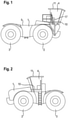
- FIG. 12 shows a side view of a tractor according to a first embodiment of the present invention.
- a driver's cab 4 is mounted on a chassis 1 with front and rear wheels 2, 3 in a position projecting forwards over the front axle.
- Behind the driver's cab 4 is a loading area 5 that offers space for loads or tools.
- the loading area 5 is lightly loaded, there is a possibility that the tractor will fall if the tractor gets on too steep a sloping ground fell forward and hit the ground with the front of the cab 4.
- FIG. 12 shows a side view of a tractor according to a second embodiment of the present invention.
- a driver's cab 4 is positioned here on a chassis 1 approximately in the middle between the front and rear axles.
- tipping over is hardly possible here; but there is (as also in the case of 1 ) the possibility of the tractor tipping sideways on steeply sloping ground so that a side wall of the driver's cab 4 touches the ground at the end, or it overturns and remains lying on the roof of the driver's cab 4.
- Figures 3 and 4 show a structure 6 of the driver's cab 4 of the tractor Fig. 1 or 2 and a section of its chassis 1 in perspective views.
- the driver's cab 4 essentially has the shape of a cuboid, and strips 7, 8, 9 of the supporting structure 6 form the edges of the cuboid and are connected to one another at its corners.
- the strips 7 form a frame which encloses a base plate 10 .
- Vertical strips 8 delimit a door opening and form the border of an in 3 windshield not shown.
- Horizontal strips 9 form a frame for a roof panel 11 (see Fig. Fig. 1 or 2 ).
- a rear wall of the driver's cab 4 is divided by a horizontal strip 12 into a lower area filled with a plate 13 made of sheet metal and an upper area, which has a 3 rear window, not shown.
- a crossbeam 15 connecting the longitudinal beams 14 comprises a horizontally elongated crossbeam 16 and two approximately vertically oriented columns 17, which bridge a height difference between the crossbeam 16 and the longitudinal beams 14.
- Transoms 16 and columns 17 each have an H- or U-shaped cross section.
- Front and rear thighs the H or U cross-sections are each formed by flat, here approximately T-shaped blanks 18 made of sheet steel, which each belong partly to one of the columns 17 and partly to the crossbeam 16; Center sections 19 connecting the legs of the H or U sections are welded to them; thus, in particular on the crossbeam 16, a projection of the front and rear legs above the middle section 19 that is variable over its length can be realized.
- Suspension struts not shown in the figures, of a type known per se are anchored on the one hand to the columns 17 and on the other hand to the front bar 7 or an adjacent front area of the floor panel 10 in order to keep the driver's cab 4 at a distance from the crossbeam 16 and a damped spring movement to allow the driver's cab 4 relative to the chassis 1 while driving the machine.
- a Panhard rod can also be provided, which is articulated in a diagonal orientation to the cross member 15 and the front bar 7 .
- a multi-layered leaf spring 20 is mounted between the portions of the front and rear legs which rise above the central portion 19 of the transom 16 .
- the middle section 19 rests in places on the sheet metal blanks 18: on the one hand, the ends 21 of the middle section 19 are wider than the distance between the blanks 18, so that the ends 21 rest on the upper edges of the blanks 18; on the other hand, the blanks 18 each have at least a slit-shaped opening 22 into which a tab of the middle section 19 projecting forwards or backwards engages.
- the front and rear panels 18 are connected to each other by two brackets 23 at their highest points.
- the leaf spring 20 is clamped between the brackets 23 and the middle section 19 .
- the driver's cab 4 is connected with play to the leaf spring 20 by a loop 24, which is anchored to the floor panel 10 of the driver's cab and extends from there as in FIG figure 5 shown extending downwardly to engage the free ends of the leaf spring 20.
- a rod 27 is inserted into the opening of the loop 24 and is fastened to the leaf spring 20 by means of screws 28 at its ends protruding from the loop 24 on both sides of the opening 26 .
- the driver's cab 4 can be pushed down until it abuts the leaf spring 20 or the crossbeam 16; when pulled upwards, the loop 24, once taut, pulls the free end of the leaf spring 20 with it, bending it in the process.
- the leaf spring 20 comprises a plurality of slats 29, 30, 31, the length of which decreases from bottom to top.
- the openings 26 are formed in the longest and consequently the lowest lamella 29 .
- the spring constant and the amount of energy dissipated per unit of deformation path therefore increases sharply with increasing deformation, so that on the one hand a moderate tensile force is already sufficient to deflect the cabin 4, but on the other hand a large amount of impact energy due to deformation of the leaf spring with a limited total deflection 20 can be dissipated.
- the cross member 15 extends under a front edge area of the floor panel 10.
- the driver's cab 4 is as in FIG 4 supported on the side members 14 by two crash boxes 32 and another cross member 33 .
- spring struts 50 are provided, which support the rear edge of the floor panel 10 and prevent the driver's cab 4 from hitting the crash boxes 32 during normal driving operation, but allow a pitching movement of the cab 4 about an axis running essentially along the leaf spring 20.
- the game containing link about the loop 24 enables the nodding movement without deformation of the leaf spring 20.
- a modified design of the leaf spring 20 in the deflected state is shown in 6 shown.
- the ends of the lowermost slat 29 and the middle section 19 are here provided with holes 34, 35, respectively, through which bolts (not shown in this figure) extending downwards from the floor 10 of the driver's cab 4 extend. Heads at the lower ends of these bolts are smaller than the holes 35 of the central section 19 so that they can pass freely through them, but smaller than the holes 34 so that when they strike the leaf spring 20 from below they bend it upwards.
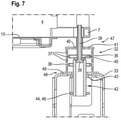
- the crash box 32 on the side facing the pressure is also exposed to tensile stress.
- the cross section of the crash box 32 shown enables it to absorb energy even under tensile stress:
- the crash box 32 has upright side walls 36 in which waves 37 are formed in a manner known per se in order to achieve reproducible compression behavior and along their upper and lower edges with cover plates 41, 48 are firmly connected.
- the shafts 37 can also absorb energy leveled when the sidewalls 36 are subjected to tensile stress.
- a connection 47 is formed between the driver's cab and the crash box by the base plate 10 - analogous to the design of the 6 -
- a bolt 38 is anchored, which engages through an opening 40 in the upper cover plate 41 of the crash box 32 in its interior and carries a head 39 there.
- the lower cover plate 48 is immovably fixed in a second connection 49 to the cross member 33 by welding, screws or the like.
- FIG. 7 shows an equilibrium position in which the freedom of movement of the driver's cab 4 downwards until the rear strip 7 touches the cover plate 41 and upwards until the head 39 hits the cover plate 41 from below is essentially the same.
- the game down is determined by the above-mentioned struts 50; the upward clearance can be adjusted if the bolt 38 and the head 39 form the shank and head of a screw which is screwed into an internal thread of the driver's cab 4.
- an opening 43 is cut out in the cross member 33 and in a second cover plate of the crash box 32 fixed immovably to the cross member, through which a screwing tool can be inserted into the crash box 32.
- a lock nut may be provided in contact with the cab 4 to fix an adjusted position of the screw.
- a washer 45 rests on the head 39 . Since its diameter is larger than that of the head, it lies down when it comes into contact with the cover plate 41 when the driver's cab 4 moves upwards its entire circumference to the latter and thus distributes a tensile force that may possibly only be transmitted at certain points by the head 39 evenly over the entire circumference of the opening 40.
- an overstretching safety device which is set up to transmit a tensile force from the bolt 38 to the cross member 33 while bypassing the crash box 32 .
- the overstretching safeguard is here an extension 42 of the bolt 38 beyond the head 39, which extends through the opening 43 of the crossbeam 33 and carries a second head 44 limiting the freedom of movement of the cabin 4 by hitting the crossbeam 33.
- the extension 42 has the shape of an upside down cup.
- the cup has a tubular stem; its upwardly facing bottom is formed by the washer 45 and the head 44 is formed by a radially outwardly directed rim 46 at the end of the shank remote from the bottom 45.
- the head 39 for a screwing tool can be reached via the hollow shaft.
- the head 39 and floor 45 are far enough below the cover plate 41 to avoid contact between the floor 45 and cover plate 41 even when the cabin 4 rocks up and down during normal driving.
- the distance between the rim 46 and the cross member 33 is greater than that between the bottom 45 and the cover plate 41 of the undeformed crash box, so that the rim 46 can only strike the cross member 33 when the crash box 32 has extended beyond the length that it is in in the intact condition has been stretched out.
Landscapes
- Engineering & Computer Science (AREA)
- Mechanical Engineering (AREA)
- Body Structure For Vehicles (AREA)
Abstract
Description
- Die vorliegende Erfindung betrifft eine selbstfahrende landwirtschaftliche Arbeitsmaschine.
- Landwirtschaftliche Arbeitsmaschinen sind häufig auf abschüssigem, unbefestigtem und eventuell nachgiebigem Untergrund im Einsatz, wo eine nicht zu vernachlässigende Wahrscheinlichkeit eines Unfalls durch Umkippen besteht. Ein erhöhtes Kipprisiko besteht etwa, wenn eine Arbeitsmaschine zum Verdichten von Silage durch Überfahren in einem Fahrsilo eingesetzt wird, da das Silagegut hier eine steile und eventuell instabile Böschung aufweisen kann. Beim Umkippen kann eine Fahrerkabine der Arbeitsmaschine in Kontakt mit dem Boden gelangen und zwischen diesem und dem Fahrgestell deformiert werden. Die Fahrerkabine muss robust genug konstruiert sein, um auch in einem solchen Fall den Fahrer wirksam zu schützen.
- Aus
DE 10 2018 005 874 A ist eine landwirtschaftliche Arbeitsmaschine bekannt, bei der die Fahrerkabine in einem rückwärtigen Bereich über Crashboxen abgestützt und um eine unter ihrer Vorderkante verlaufende Achse schwenkbar ist, so dass von vorn auf die Kabine einwirkender Druck ein Schwenken der Kabine um die Achse und in der Folge eine Stauchung der Crashboxen bewirken kann. Im Fall eines Vornüberkippens der Arbeitsmaschine sind beide Crashboxen wirksam. Wenn jedoch die Arbeitsmaschine seitwärts umkippt, dann gerät im Wesentlichen nur die bodenabgewandte Crashbox unter Druck; die andere bleibt wirkungslos. - Eine Aufgabe der Erfindung ist, eine landwirtschaftliche Arbeitsmaschine mit zwischen einem Fahrgestell und einer Fahrerkabine angeordneten Crashboxen zu schaffen, bei der auch eine nach einem Seitwärtsumkippen bodennahe Crashbox zur Dissipation von Aufprallenergie und damit zum Schutz der Fahrerkabine vor übermäßiger Deformation beitragen kann.
- Die Aufgabe wird gelöst, indem bei einer landwirtschaftlichen Arbeitsmaschine, bei der ein Fahrgestell ein erstes Karosserieteil und eine Fahrerkabine ein über dem ersten Karosserieteil angeordnetes und relativ zum Fahrgestell bewegliches zweites Karosserieteil bildet und wenigstens eine Crashbox zwischen der Fahrerkabine und dem Fahrgestell angeordnet ist, um durch eine sich dem Fahrgestell annähernde Bewegung der Fahrerkabine gestaucht zu werden, jeweils eine zugbelastbare Verbindung zwischen der Crashbox und der Fahrerkabine sowie zwischen der Crashbox und dem Fahrgestell vorgesehen ist. So kann die Crashbox Energie nicht nur dadurch aufnehmen, dass sie wie üblich gestaucht wird, sondern auch dadurch, dass sie in die Länge gezogen wird.
- Wenigstens eine der Verbindungen sollte ein Spiel in Richtung der Relativbewegung aufweisen, um eine Bewegung der Fahrerkabine relativ zum Fahrgestell ohne Deformation der Crashbox zuzulassen.
- Die Karosserieteile sollten ferner durch eine Feder verbunden sein, die bemessen ist, um die wenigstens eine Verbindung in einer Mittelstellung zwischen den Grenzen des Spiels zu halten. So kann die Fahrerkabine vor Erschütterungen des Fahrgestells während der Fahrt abgeschirmt werden.
- Um die Relativbewegung von Fahrgestell und Fahrerkabine im Wesentlichen auf einen einzigen Freiheitsgrad einzuschränken, kann benachbart zu einer vorderen Kante der Fahrerkabine eine Achse definiert sein, um die die Fahrerkabine relativ zum Fahrgestell schwenkbar ist.
- Die Achse ist vorzugsweise unter normalen Betriebsbedingungen am Fahrgestell fest, kann aber ihrerseits bei einem Unfall unter Energieaufnahme relativ zum Fahrgestell bewegbar sein.
- Die Beweglichkeit relativ zum Fahrgestell kann dadurch erreicht werden, dass eine sich in Querrichtung der Arbeitsmaschine erstreckende Blattfeder mittig an einem der Karosserieteile, vorzugsweise dem Fahrgestell, und an ihren Enden mit dem anderen Karosserieteil, vorzugsweise der Fahrerkabine, verbunden ist.
- Insbesondere kann ein Querträger des Fahrgestells sich über die gesamte Länge der Blattfeder erstrecken, um diese bei normaler Fahrt sowohl in der Mitte als auch an den mit der Fahrerkabine verbundenen Enden zu unterstützen.
- Vorzugsweise ist die Verbindung der Crashbox zum Fahrgestell spielfrei; d.h. bei normaler Fahrt findet eine Relativbewegung nur zwischen der Crashbox und der Fahrgastzelle statt.
- Die Crashbox kann in an sich bekannter Weise verformbare Seitenwände (36) und wenigstens eine an den Seitenplatten befestigte Deckplatte aufweisen. Eine der Verbindungen umfasst dann vorzugsweise einen Bolzen, der sich durch eine Öffnung der Deckplatte erstreckt, und einen ersten Kopf im Innern der Crashbox. Der Querschnitt der Öffnung ist bemessen, um eine Bewegung des Bolzens in Richtung der Relativbewegung zuzulassen; zu einer Deformation der Crashbox kommt es erst dann, wenn entweder das eine Karosserieteil, an dem der Bolzen befestigt ist, von außen gegen die Deckplatte drückt, oder wenn der Kopf von innen anschlägt und dadurch die Seitenwände in die Länge zieht.
- Um den Zusammenbau zu erleichtern, sollte der erste Kopf über eine Öffnung an einer der Deckplatte gegenüberliegenden Seite der Crashbox zugänglich sein.
- Wenn der Bolzen ein Außengewinde aufweist, das in ein komplementäres Innengewinde des einen Karosserieteils eingreift, dann kann durch Drehen des Bolzens die Bewegungsfreiheit des ersten Kopfs relativ zur Deckplatte justiert werden. Um ein dafür erforderliches Drehmoment auf den ersten Kopf ausüben zu können, ist die oben erwähnte Öffnung an der der Deckplatte gegenüberliegenden Seite der Crashbox hilfreich.
- Eine Unterlegscheibe zwischen dem ersten Kopf und der Deckplatte ist hilfreich, um die Zugkraft des ersten Kopfs in die Deckplatte gleichmäßig um deren Öffnung herum verteilt einzuleiten und einer lokalen Überbeanspruchung vorzubeugen.
- Um ein Aufreißen der Crashbox unter einer übermäßigen Zugbelastung zu vermeiden, kann zwischen den Karosserieteilen eine Überdehnungssicherung vorgesehen sein, die eine Zugkraft zwischen beiden aufnimmt, sobald die Crashbox bis an eine zulässige Grenze gedehnt ist.
- Eine solche Überdehnungssicherung kann als eine Verlängerung des Bolzens über den ersten Kopf hinaus realisiert sein, die sich ihrerseits durch eine Öffnung des anderen Karosserieteils hindurch erstreckt und einen zweiten Kopf an einer von der Crashbox abgewandten Seite der Öffnung aufweist.
- Die oben erwähnte Unterlegscheibe kann Teil der Überdehnungssicherung sein; insbesondere kann eine die Unterlegscheibe integrierende Überdehnungssicherung relativ zum Bolzen beweglich sein.
- Insbesondere kann die Überdehnungssicherung die Form eines Bechers hat, wobei der Bolzen eine Öffnung im Boden des Bechers durchsetzt (m.a.W. die Unterlegscheibe den Boden des Bechers bildet) und der erste Kopf (39) im Innern des Bechers gehalten ist.
- Weitere Merkmale und Vorteile der Erfindung ergeben sich aus der nachfolgenden Beschreibung von Ausführungsbeispielen unter Bezugnahme auf die beigefügten Figuren. Es zeigen:
- Fig. 1
- eine Seitenansicht einer landwirtschaftlichen Arbeitsmaschine gemäß einer ersten Ausgestaltung der Erfindung;
- Fig. 2
- eine zu
Figur 1 analoge Seitenansicht gemäß einer zweiten Ausgestaltung; - Fig. 3 und 4
- perspektivische Ansichten der Fahrerkabine und eines Teils des Fahrgestells;
- Fig. 5
- eine spielhaltige Verbindung zwischen Fahrerkabine und Fahrgestell;
- Fig. 6
- eine Abwandlung der spielhaltigen Verbindung; und
- Fig. 7
- einen Schnitt durch eine Crashbox.
-
Fig. 1 zeigt eine Seitenansicht eines Traktors gemäß einer ersten Ausgestaltung der vorliegenden Erfindung. Auf einem Fahrgestell 1 mit Vorder- und Hinterrädern 2, 3 ist in über die Vorderachse nach vorn vorstehender Stellung eine Fahrerkabine 4 montiert. Hinter der Fahrerkabine 4 erstreckt sich eine Ladefläche 5, die Platz für Lasten oder Werkzeuge bietet. Insbesondere wenn die Ladefläche 5 wenig beladen ist, besteht, wenn der Traktor auf zu steil abschüssigen Untergrund gerät, die Möglichkeit, dass der Traktor vornüberkippt und mit der Vorderseite der Fahrerkabine 4 auf den Boden schlägt. -
Fig. 2 zeigt eine Seitenansicht eines Traktors gemäß einer zweiten Ausgestaltung der vorliegenden Erfindung. Eine Fahrerkabine 4 ist hier auf einem Fahrgestell 1 in etwa mittig zwischen Vorder- und Hinterachsen positioniert. Ein Vornüberkippen ist hier in der Praxis kaum möglich; es besteht aber (wie auch im Fall derFig. 1 ) die Möglichkeit, dass der Traktor auf seitwärts stark abschüssigem Untergrund zur Seite kippt, so dass am Ende eine Seitenwand der Fahrerkabine 4 den Boden berührt, oder er sich überschlägt und auf dem Dach der Fahrerkabine 4 liegenbleibt. -
Fig. 3 und 4 zeigen ein Tragwerk 6 der Fahrerkabine 4 des Traktors ausFig. 1 oder 2 sowie einen Ausschnitt seines Fahrgestells 1 in perspektivischen Ansichten. - Die Fahrerkabine 4 hat im Wesentlichen die Form eines Quaders, und Leisten 7, 8, 9 des Tragwerks 6 bilden die Kanten des Quaders und sind an dessen Ecken untereinander verbunden. Die Leisten 7 bilden einen Rahmen, der eine Bodenplatte 10 einfasst. Vertikale Leisten 8 begrenzen eine Türöffnung und bilden die Einfassung einer in
Fig. 3 nicht gezeigten Frontscheibe. - Horizontale Leisten 9 bilden einen Rahmen für eine Dachplatte 11 (s.
Fig. 1 oder 2 ). Eine Rückwand der Fahrerkabine 4 ist durch eine horizontale Leiste 12 unterteilt in einen durch eine Platte 13 aus Blech ausgefüllten unteren Bereich und einen oberen Bereich, der eine inFig. 3 nicht gezeigte Heckscheibe aufnimmt. - Unter der Fahrerkabine 4 erstrecken sich zwei Längsträger 14 des Fahrgestells 1. Ein die Längsträger 14 verbindender Querträger 15 umfasst einen horizontal langgestreckten Querbalken 16 sowie zwei in etwa vertikal orientierte Säulen 17, die einen Höhenunterschied zwischen dem Querbalken 16 und den Längsträgern 14 überbrücken. Querbalken 16 und Säulen 17 haben jeweils einen H- oder U-förmigen Querschnitt. Vordere und hintere Schenkel der H- oder U- Querschnitte sind jeweils durch flache, hier in etwa T-förmige Zuschnitte 18 aus Stahlblech gebildet, die jeweils teils einer der Säulen 17 und teils dem Querbalken 16 angehören; Mittelabschnitte 19, die die Schenkel der H- oder U-Querschnitte verbinden, sind mit diesen verschweißt; so ist insbesondere am Querbalken 16 ein über dessen Länge hinweg variabler Überstand der vorderen und hinteren Schenkel über den Mittelabschnitt 19 nach oben realisierbar.
- In den Figuren nicht gezeigte Federbeine von an sich bekannter Bauart sind einerseits an den Säulen 17, andererseits an der vorderen Leiste 7 oder einem daran angrenzenden vorderen Bereich der Bodenplatte 10 verankert, um die Fahrerkabine 4 von dem Querbalken 16 beabstandet zu halten und eine gedämpfte Federbewegung der Fahrerkabine 4 relativ zum Fahrgestell 1 während der Fahrt der Maschine zu ermöglichen. Um die Federbeweglichkeit der Fahrerkabine 4 im Wesentlichen auf die Vertikalrichtung einzuschränken, kann ferner ein Panhardstab vorgesehen sein, der in einer diagonalen Orientierung an den Querträger 15 und die vordere Leiste 7 angelenkt ist.
- Eine mehrlagige Blattfeder 20 ist zwischen den über den Mittelabschnitt 19 des Querbalkens 16 aufragenden Teilen von dessen vorderen und hinteren Schenkeln angebracht. Der Mittelabschnitt 19 liegt stellenweise auf den Blechzuschnitten 18 auf: zum einen sind die Enden 21 des Mittelabschnitts 19 breiter als der Abstand zwischen den Zuschnitten 18, so dass die Enden 21 auf den Oberkanten der Zuschnitte 18 aufliegen, zum anderen weisen die Zuschnitte 18 jeweils wenigstens eine schlitzförmige Öffnung 22 auf, in die eine nach vorn bzw. hinten überstehende Lasche des Mittelabschnitts 19 eingreift.
- Die vorderen und hinteren Zuschnitte 18 sind an ihren höchsten Punkten untereinander durch zwei Bügel 23 verbunden. Die Blattfeder 20 ist zwischen den Bügeln 23 und dem Mittelabschnitt 19 eingeklemmt.
- Die Fahrerkabine 4 ist mit der Blattfeder 20 durch eine Schlaufe 24 spielhaltig verbunden, die an der Bodenplatte 10 der Fahrerkabine verankert ist und sich von dort wie in
Fig. 5 gezeigt nach unten erstreckt, um an den freien Enden der Blattfeder 20 anzugreifen. Am freien Ende der Blattfeder 20 ist eine - hier randoffene - Öffnung 26 ausgeschnitten. Ein Stab 27 ist in die Öffnung der Schlaufe 24 eingesteckt und an seinen aus der Schlaufe 24 überstehenden Enden beiderseits der Öffnung 26 mit Hilfe von Schrauben 28 an der Blattfeder 20 befestigt. So kann die Fahrerkabine 4 bei einem Unfall abwärts gedrückt werden, bis sie an die Blattfeder 20 oder den Querbalken 16 anstößt; wenn sie nach oben gezogen wird, zieht die Schlaufe 24, sobald sie straff gespannt ist, das freie Ende der Blattfeder 20 mit sich und verbiegt diese dabei. - Die Blattfeder 20 umfasst mehrere Lamellen 29, 30, 31, deren Länge von unten nach oben abnimmt. Die Öffnungen 26 sind in der längsten und folglich der untersten Lamelle 29 gebildet. Je stärker das freie Ende der Blattfeder 20 nach oben gezogen wird, umso größer wird die Zahl der Lamellen 29, 30, 31, die von der Deformation betroffen sind. Die Federkonstante und die Menge der pro Einheit des Deformationswegs dissipierten Energie nimmt daher mit wachsender Deformation stark zu, so dass zwar einerseits bereits eine mäßige Zugkraft ausreicht, um die Kabine 4 auszulenken, andererseits aber bei begrenzter Gesamtauslenkung eine große Menge an Aufprallenergie durch Verformung der Blattfeder 20 dissipiert werden kann.
- Der Querträger 15 erstreckt sich unter einem vorderen Randbereich der Bodenplatte 10. An ihrer Rückseite ist die Fahrerkabine 4 wie in
Fig. 4 zu sehen durch zwei Crashboxen 32 und einen weiteren Querträger 33 an den Längsträgern 14 abgestützt. Außerdem sind benachbart zu den Crashboxen 32 wie inDE 10 2018 005 874 A beschrieben, Federbeine 50 vorgesehen, die den hinteren Rand der Bodenplatte 10 stützen und im normalen Fahrbetrieb ein Aufschlagen der Fahrerkabine 4 auf die Crashboxen 32 verhindern, aber eine Nickbewegung der Kabine 4 um eine im Wesentlichen entlang der Blattfeder 20 verlaufende Achse zulassen. Die spielhaltige Verbindung über die Schlaufe 24 ermöglicht die Nickbewegung ohne Deformation der Blattfeder 20. - Eine abgewandelte Bauform der Blattfeder 20 in ausgelenktem Zustand ist in
Fig. 6 gezeigt. Die Enden der untersten Lamelle 29 und des Mittelabschnitts 19 sind hier jeweils mit Löchern 34, 35 versehen, durch die sich (in dieser Fig. nicht gezeigte) sich vom Boden 10 der Fahrerkabine 4 abwärts erstreckende Bolzen erstrecken. Köpfe an den unteren Enden dieser Bolzen sind kleiner als die Löcher 35 des Mittelabschnitts 19, so dass sie diese ungehindert durchlaufen können, aber kleiner als die Löcher 34, so dass sie, wenn sie von unten an die Blattfeder 20 anschlagen, diese aufwärts biegen. - Wie eingangs mit Bezug auf
Fig. 1 und 2 erläutert, können bei einem Unfall insbesondere Kräfte von vorn oder aus seitlicher Richtung auf die Fahrerkabine 4 einwirken. Den Kräften von vorn kann die Fahrerkabine 4 im Wesentlichen unter Beibehaltung ihrer Form nachgeben, indem sie beide Crashboxen 32 staucht und die freien Enden der Blattfeder 20 nach oben zieht. - Wenn bei einem Unfall Druck aus seitlicher Richtung auf die Fahrerkabine 4 einwirkt, dann führt dies zu einer Stauchbeanspruchung der Crashbox 32 und einem Anschlagen der Kabine 4 an die Blattfeder 20 an der druckabgewandten Seite der Kabine 4 und zu einer Zugbeanspruchung auf der druckzugewandten Seite. Die Stauchbeanspruchung wird zum Teil bestimmungsgemäß von der Crashbox 32 aufgenommen.. Auf der druckzugewandten Seite kann die Blattfeder 20 durch Verbiegung, wie oben erläutert, eine große Menge an Energie aufnehmen.
- Auch die Crashbox 32 auf der druckzugewandten Seite ist einer Zugbeanspruchung ausgesetzt. Der in
Fig. 7 gezeigte Querschnitt der Crashbox 32 ermöglicht es dieser, auch bei Zugbeanspruchung Energie aufzunehmen: Die Crashbox 32 hat aufrechte Seitenwände 36, in denen in an sich bekannter Weise Wellen 37 geformt sind, um ein reproduzierbares Stauchverhalten zu erzielen, und die entlang ihrer oberen und unteren Kanten mit Deckplatten 41, 48 fest verbunden sind. Die Wellen 37 können aber auch unter Energieaufnahme eingeebnet werden, wenn die Seitenwände 36 einer Zugbeanspruchung ausgesetzt sind. Um eine solche Zugbeanspruchung im Bedarfsfall erzeugen zu können, ist eine Verbindung 47 zwischen der Fahrerkabine und der Crashbox gebildet, indem an der Bodenplatte 10 - analog zur Ausgestaltung derFig. 6 - ein Bolzen 38 verankert ist, der durch eine Öffnung 40 in der oberen Deckplatte 41 der Crashbox 32 in deren Innenraum eingreift und dort einen Kopf 39 trägt. Die untere Deckplatte 48 ist in einer zweiten Verbindung 49 unbeweglich, durch Schweißung, Schrauben o.dgl., am Querträger 33 befestigt. Indem der Kopf 39 bei einer Aufwärtsbewegung der Fahrerkabine 4 die obere Deckplatte 41 mit sich zieht, kann er die Seitenwände 36 vertikal in die Länge ziehen. Diese Möglichkeit besteht, wenn die Crashbox 32 intakt und unverformt ist, aber in noch größerem Umfang, wenn sie bereits im Rahmen des Unfallgeschehens gestaucht worden ist. Dies ist insbesondere dann von Vorteil, wenn die Kabine 4, z.B. bei einem Überrollvorgang, Belastungen in wechselnden Richtungen ausgesetzt ist. -
Fig. 7 zeigt eine Gleichgewichtsstellung, in der die Bewegungsfreiheit der Fahrerkabine 4 nach unten bis zu einem Aufsetzen der hinteren Leiste 7 auf die Deckplatte 41 und nach oben bis zu einem Anschlagen des Kopfes 39 von unten an die Deckplatte 41 im Wesentlichen gleich ist. Das Spiel nach unten ist durch die oben erwähnten Federbeine 50 bestimmt; das Spiel nach oben kann justiert werden, wenn der Bolzen 38 und der Kopf 39 Schaft und Kopf einer Schraube bilden, die in ein Innengewinde der Fahrerkabine 4 eingeschraubt ist. Um zu diesem Zweck ein Drehmoment auf den Kopf 39 ausüben zu können, sind im Querträger 33 und einer auf dem Querträger unbeweglich befestigten zweiten Deckplatte der Crashbox 32 eine Öffnung 43 ausgespart, über die ein Schraubwerkzeug in die Crashbox 32 eingeführt werden kann. Eine nicht dargestellte Kontermutter kann in Kontakt mit der Fahrerkabine 4 vorgesehen sein, um eine eingestellte Stellung der Schraube zu fixieren. - Auf dem Kopf 39 liegt eine Unterlegscheibe 45 auf. Da deren Durchmesser größer ist als der des Kopfes, legt sie sich, wenn sie bei einer Aufwärtsbewegung der Fahrerkabine 4 mit der Deckscheibe 41 in Kontakt kommt, auf ihrem gesamten Umfang an letztere an und verteilt so eine vom Kopf 39 möglicherweise nur punktuell übertragene Zugkraft gleichmäßig über den gesamten Umfang der Öffnung 40.
- Um zu verhindern, dass eine übermäßige Zugbeanspruchung der Deckplatte 41 zu einem Abreißen führt, ist eine Überdehnungssicherung vorgesehen, die eingerichtet ist, eine Zugkraft des Bolzens 38 unter Umgehung der Crashbox 32 auf den Querträger 33 zu übertragen. Die Überdehnungssicherung ist hier eine Verlängerung 42 des Bolzens 38 über den Kopf 39 hinaus, die die Öffnung 43 des Querträgers 33 durchgreift und einen zweiten, die Bewegungsfreiheit der Kabine 4 durch Anschlagen am Querträger 33 begrenzenden Kopf 44 trägt. Im hier gezeigten Fall hat die Verlängerung 42 die Form eines auf dem Kopf stehenden Bechers. Der Becher hat einen rohrförmigen Schaft; sein nach oben gekehrter Boden ist durch die Unterlegscheibe 45 gebildet ist, und der Kopf 44 ist durch eine radial nach außen gerichtete Krempe 46 am vom Boden 45 abgewandten Ende des Schafts gebildet. Über den hohlen Schaft ist der Kopf 39 für ein Schraubwerkzeug erreichbar. Im Stillstand der Arbeitsmaschine liegen Kopf 39 und Boden 45 weit genug unter der Deckplatte 41, um einen Kontakt zwischen Boden 45 und Deckplatte 41 auch dann zu vermeiden, wenn die Kabine 4 im normalen Fahrbetrieb auf und ab wippt. Der Abstand zwischen der Krempe 46 und dem Querträger 33 ist größer als der zwischen Boden 45 und Deckplatte 41 der unverformten Crashbox, so dass die Krempe 46 erst dann an den Querträger 33 anschlagen kann, wenn die Crashbox 32 über die Länge, die sie im intakten Zustand aufweist, hinaus gedehnt worden ist.
-
- 1
- Fahrgestell
- 2
- Vorderrad
- 3
- Hinterrad
- 4
- Fahrerkabine
- 5
- Ladefläche
- 6
- Tragwerk
- 7
- Leiste
- 8
- Leiste
- 9
- Leiste
- 10
- Bodenplatte
- 11
- Dachplatte
- 12
- Leiste
- 13
- Platte
- 14
- Längsträger
- 15
- Querträger
- 16
- Querbalken
- 17
- Säule
- 18
- Zuschnitt
- 19
- Mittelabschnitt
- 20
- Blattfeder
- 21
- Ende von 19
- 22
- Öffnung
- 23
- Bügel
- 24
- Schlaufe
- 25 26
- Öffnung
- 27
- Kopf
- 28
- Schraube
- 29
- Lamelle
- 30
- Lamelle
- 31
- Lamelle
- 32
- Crashbox
- 33
- Querträger
- 34
- Loch
- 35
- Loch
- 36
- Seitenwand
- 37
- Welle
- 38
- Bolzen
- 39
- Kopf
- 40
- Öffnung
- 41
- Deckplatte
- 42
- Verlängerung
- 43
- Öffnung
- 44
- Kopf
- 45
- Boden
- 46
- Krempe
- 47
- Verbindung
- 48
- Deckplatte
- 49
- Verbindung
- 50
- Federbein
Claims (12)
- Landwirtschaftliche Arbeitsmaschine, bei der ein Fahrgestell (1) ein erstes Karosserieteil (1) und eine Fahrerkabine (4) ein über dem ersten Karosserieteil (1) angeordnetes und relativ zum Fahrgestell bewegliches zweites Karosserieteil (4) bildet und wenigstens eine Crashbox (32) zwischen der Fahrerkabine (4) und dem Fahrgestell (1) angeordnet ist, um durch eine sich dem Fahrgestell (1) annähernde Bewegung der Fahrerkabine (4) gestaucht zu werden, dadurch gekennzeichnet, dass jeweils eine zugbelastbare Verbindung (47, 49) zwischen der Crashbox (32) und der Fahrerkabine (4) sowie zwischen der Crashbox (32) und dem Fahrgestell (1) vorgesehen ist.
- Landwirtschaftliche Arbeitsmaschine nach Anspruch 1, dadurch gekennzeichnet, dass wenigstens eine der Verbindungen (47) ein Spiel in Richtung der Relativbewegung aufweist.
- Landwirtschaftliche Arbeitsmaschine nach Anspruch 2, dadurch gekennzeichnet, dass die Karosserieteile (1, 4) ferner durch eine Feder (25) verbunden sind, die bemessen ist, um die wenigstens eine Verbindung (47) in einer Mittelstellung zwischen den Grenzen des Spiels zu halten.
- Landwirtschaftliche Arbeitsmaschine nach Anspruch 1 oder 2, dadurch gekennzeichnet, dass die Relativbewegung eine Schwenkbewegung um eine zu einer vorderen Kante der Fahrerkabine benachbarte Achse ist.
- Landwirtschaftliche Arbeitsmaschine nach einem der vorhergehenden Ansprüche, dadurch gekennzeichnet, dass die Verbindung (49) zwischen der Crashbox (32) und dem Fahrgestell (1) spielfrei ist.
- Landwirtschaftliche Arbeitsmaschine nach einem der vorhergehenden Ansprüche, dadurch gekennzeichnet, dass die Crashbox (32) verformbare Seitenwände (36) und wenigstens eine an den Seitenplatten befestigte Deckplatte (41) aufweist, und dass eine der Verbindungen (47) einen Bolzen (38), der sich durch eine Öffnung der Deckplatte (41) erstreckt, und einen ersten Kopf (39) im Innern der Crashbox (32) umfasst.
- Landwirtschaftliche Arbeitsmaschine nach Anspruch 6, dadurch gekennzeichnet, dass der erste Kopf (39) über eine Öffnung (43) an einer der Deckplatte gegenüberliegenden Seite der Crashbox (32) zugänglich ist.
- Landwirtschaftliche Arbeitsmaschine nach Anspruch 6 oder 7, dadurch gekennzeichnet, dass der Bolzen (38) ein Außengewinde aufweist, das in ein komplementäres Innengewinde eines der Karosserieteile (4) eingreift.
- Landwirtschaftliche Arbeitsmaschine nach Anspruch 6, 7 oder 8, dadurch gekennzeichnet, dass eine Unterlegscheibe (45) zwischen dem ersten Kopf (39) und der Deckplatte (41) vorgesehen ist.
- Landwirtschaftliche Arbeitsmaschine nach einem der Ansprüche 6 bis 9, dadurch gekennzeichnet, dass eine Überdehnungssicherung zwischen den Karosserieteilen (1, 4) vorgesehen ist, um eine Zugkraft zwischen beiden aufzunehmen, sobald die Crashbox (32) bis an eine zulässige Grenze gedehnt ist.
- Landwirtschaftliche Arbeitsmaschine nach Anspruch 10, dadurch gekennzeichnet, dass die Überdehnungssicherung den Bolzen (38) bis durch eine Öffnung (43) des anderen Karosserieteils (1) hindurch verlängert und einen zweiten Kopf (44) an einer von der Crashbox (32) abgewandten Seite der Öffnung (43) aufweist.
- Landwirtschaftliche Arbeitsmaschine nach Anspruch 10 oder 11, dadurch gekennzeichnet, dass die Überdehnungssicherung die Form eines Bechers hat, wobei der Bolzen (38) eine Öffnung im Boden des Bechers durchsetzt und der erste Kopf (39) im Innern des Bechers gehalten ist.
Applications Claiming Priority (1)
| Application Number | Priority Date | Filing Date | Title |
|---|---|---|---|
| DE102020124720.6A DE102020124720A1 (de) | 2020-09-22 | 2020-09-22 | Landwirtschaftliche Arbeitsmaschine |
Publications (2)
| Publication Number | Publication Date |
|---|---|
| EP3971043A1 true EP3971043A1 (de) | 2022-03-23 |
| EP3971043B1 EP3971043B1 (de) | 2023-11-01 |
Family
ID=77168118
Family Applications (1)
| Application Number | Title | Priority Date | Filing Date |
|---|---|---|---|
| EP21189117.1A Active EP3971043B1 (de) | 2020-09-22 | 2021-08-02 | Landwirtschaftliche arbeitsmaschine |
Country Status (2)
| Country | Link |
|---|---|
| EP (1) | EP3971043B1 (de) |
| DE (1) | DE102020124720A1 (de) |
Cited By (1)
| Publication number | Priority date | Publication date | Assignee | Title |
|---|---|---|---|---|
| FI20245437A1 (fi) * | 2024-04-08 | 2025-10-09 | Ponsse Oyj | Työkoneen ohjaamo, työkone ja menetelmä työkoneen ohjaamon mitoittamiseksi |
Citations (7)
| Publication number | Priority date | Publication date | Assignee | Title |
|---|---|---|---|---|
| US3560019A (en) * | 1969-05-22 | 1971-02-02 | Portland Wire & Iron Works | Shock cushioning mounting means for canopies on heavy equipment |
| US4143903A (en) * | 1976-07-22 | 1979-03-13 | Kabushiki Kaisha Komatsu Seisakusho | Mounting apparatus of driver's cab for earth moving vehicle |
| GB2013142A (en) * | 1978-01-25 | 1979-08-08 | Kippencourt Ltd | Tractor Cabs |
| US5964310A (en) * | 1997-12-12 | 1999-10-12 | Caterpillar Inc. | Operator's station supporting structure |
| EP2484579A2 (de) * | 2011-02-02 | 2012-08-08 | CNH Italia S.p.A. | Überrollschutzsystembefestigung für aufgehängte Fahrerkabinen für einen landwirtschaftlichen Traktor mit Vierradantrieb |
| DE102015214456A1 (de) * | 2015-07-30 | 2017-02-02 | Deere & Company | Kabinenlagerungsanordnung für ein Nutzfahrzeug |
| DE102018005874A1 (de) | 2018-07-25 | 2020-01-30 | Claas Selbstfahrende Erntemaschinen Gmbh | Landwirtschaftliche Arbeitsmaschine |
-
2020
- 2020-09-22 DE DE102020124720.6A patent/DE102020124720A1/de active Pending
-
2021
- 2021-08-02 EP EP21189117.1A patent/EP3971043B1/de active Active
Patent Citations (8)
| Publication number | Priority date | Publication date | Assignee | Title |
|---|---|---|---|---|
| US3560019A (en) * | 1969-05-22 | 1971-02-02 | Portland Wire & Iron Works | Shock cushioning mounting means for canopies on heavy equipment |
| US4143903A (en) * | 1976-07-22 | 1979-03-13 | Kabushiki Kaisha Komatsu Seisakusho | Mounting apparatus of driver's cab for earth moving vehicle |
| GB2013142A (en) * | 1978-01-25 | 1979-08-08 | Kippencourt Ltd | Tractor Cabs |
| US5964310A (en) * | 1997-12-12 | 1999-10-12 | Caterpillar Inc. | Operator's station supporting structure |
| EP2484579A2 (de) * | 2011-02-02 | 2012-08-08 | CNH Italia S.p.A. | Überrollschutzsystembefestigung für aufgehängte Fahrerkabinen für einen landwirtschaftlichen Traktor mit Vierradantrieb |
| DE102015214456A1 (de) * | 2015-07-30 | 2017-02-02 | Deere & Company | Kabinenlagerungsanordnung für ein Nutzfahrzeug |
| DE102018005874A1 (de) | 2018-07-25 | 2020-01-30 | Claas Selbstfahrende Erntemaschinen Gmbh | Landwirtschaftliche Arbeitsmaschine |
| EP3608213A1 (de) * | 2018-07-25 | 2020-02-12 | CLAAS Selbstfahrende Erntemaschinen GmbH | Landwirtschaftliche arbeitsmaschine |
Cited By (1)
| Publication number | Priority date | Publication date | Assignee | Title |
|---|---|---|---|---|
| FI20245437A1 (fi) * | 2024-04-08 | 2025-10-09 | Ponsse Oyj | Työkoneen ohjaamo, työkone ja menetelmä työkoneen ohjaamon mitoittamiseksi |
Also Published As
| Publication number | Publication date |
|---|---|
| EP3971043B1 (de) | 2023-11-01 |
| DE102020124720A1 (de) | 2022-03-24 |
Similar Documents
| Publication | Publication Date | Title |
|---|---|---|
| DE69629839T2 (de) | Kraftfahrzeugvorderbau, und verfahren zum absorbieren der aufprallenergie durch diesen vorderbau | |
| DE69934077T2 (de) | Fahrzeug-Verzögerungsverfahren und Strassen-Aufpralldämpfer zur Durchführung davon | |
| DE10234438B4 (de) | Stoßfängeraufhängung für Fahrzeuge | |
| DE10350451B4 (de) | Stossfängergerät | |
| DE2757421A1 (de) | Stossabsorbierende vorrichtung | |
| DE2845548C2 (de) | ||
| WO2003039915A1 (de) | Frontstruktur eines kraftfahrzeuges | |
| EP2558360A2 (de) | Luftfahrzeug mit einer integrierten energieaufnehmenden verformungsstruktur und luftfahrzeug mit einem derartigen rumpf | |
| DE2600937C2 (de) | ||
| EP2064104A1 (de) | Kopfmodul für ein schienenfahrzeug | |
| WO2012076006A9 (de) | Vorrichtung zur befestigung von tür- oder klappenscharnieren oder anderen elementen an den türen oder klappen oder an der karosserie von kraftfahrzeugen | |
| EP1160133B1 (de) | Deformationselement | |
| EP3971043B1 (de) | Landwirtschaftliche arbeitsmaschine | |
| EP3608213B1 (de) | Landwirtschaftliche arbeitsmaschine | |
| DE10040272C2 (de) | Rammpuffer | |
| DE10028704A1 (de) | Kraftfahrzeug mit Aggregateabsenkung | |
| DE102015004416A1 (de) | Frontpartie für ein Kraftfahrzeug | |
| EP3702187B1 (de) | Aufprallschutzverstärkung einer fahrzeugkonstruktion sowie verbindungs- und herstellungsverfahren dafür | |
| DE102020124719A1 (de) | Landwirtschaftliche Arbeitsmaschine | |
| DE602004004613T2 (de) | Schutzstruktur für Fahrzeug | |
| EP0621170A1 (de) | Vordere Lageranordnung für das Fahrerhaus eines Lastkraftwagens | |
| DE10232799A1 (de) | Vorbaustruktur an Kraftfahrzeugen | |
| WO2023083547A1 (de) | Energiespeicher-bodenanlage für einen elektrisch antreibbaren kraftwagen | |
| WO2006136318A1 (de) | Kraftfahrzeug | |
| EP3851683B1 (de) | Befestigungselement, einbauelement für fahrzeuge und fahrzeug |
Legal Events
| Date | Code | Title | Description |
|---|---|---|---|
| PUAI | Public reference made under article 153(3) epc to a published international application that has entered the european phase |
Free format text: ORIGINAL CODE: 0009012 |
|
| STAA | Information on the status of an ep patent application or granted ep patent |
Free format text: STATUS: THE APPLICATION HAS BEEN PUBLISHED |
|
| AK | Designated contracting states |
Kind code of ref document: A1 Designated state(s): AL AT BE BG CH CY CZ DE DK EE ES FI FR GB GR HR HU IE IS IT LI LT LU LV MC MK MT NL NO PL PT RO RS SE SI SK SM TR |
|
| STAA | Information on the status of an ep patent application or granted ep patent |
Free format text: STATUS: REQUEST FOR EXAMINATION WAS MADE |
|
| 17P | Request for examination filed |
Effective date: 20220923 |
|
| RBV | Designated contracting states (corrected) |
Designated state(s): AL AT BE BG CH CY CZ DE DK EE ES FI FR GB GR HR HU IE IS IT LI LT LU LV MC MK MT NL NO PL PT RO RS SE SI SK SM TR |
|
| RIC1 | Information provided on ipc code assigned before grant |
Ipc: B60R 21/13 20060101AFI20230424BHEP |
|
| GRAP | Despatch of communication of intention to grant a patent |
Free format text: ORIGINAL CODE: EPIDOSNIGR1 |
|
| STAA | Information on the status of an ep patent application or granted ep patent |
Free format text: STATUS: GRANT OF PATENT IS INTENDED |
|
| P01 | Opt-out of the competence of the unified patent court (upc) registered |
Effective date: 20230516 |
|
| INTG | Intention to grant announced |
Effective date: 20230602 |
|
| GRAS | Grant fee paid |
Free format text: ORIGINAL CODE: EPIDOSNIGR3 |
|
| GRAA | (expected) grant |
Free format text: ORIGINAL CODE: 0009210 |
|
| STAA | Information on the status of an ep patent application or granted ep patent |
Free format text: STATUS: THE PATENT HAS BEEN GRANTED |
|
| AK | Designated contracting states |
Kind code of ref document: B1 Designated state(s): AL AT BE BG CH CY CZ DE DK EE ES FI FR GB GR HR HU IE IS IT LI LT LU LV MC MK MT NL NO PL PT RO RS SE SI SK SM TR |
|
| REG | Reference to a national code |
Ref country code: GB Ref legal event code: FG4D Free format text: NOT ENGLISH |
|
| REG | Reference to a national code |
Ref country code: CH Ref legal event code: EP |
|
| REG | Reference to a national code |
Ref country code: IE Ref legal event code: FG4D Free format text: LANGUAGE OF EP DOCUMENT: GERMAN |
|
| REG | Reference to a national code |
Ref country code: DE Ref legal event code: R096 Ref document number: 502021001837 Country of ref document: DE |
|
| REG | Reference to a national code |
Ref country code: LT Ref legal event code: MG9D |
|
| REG | Reference to a national code |
Ref country code: NL Ref legal event code: MP Effective date: 20231101 |
|
| PG25 | Lapsed in a contracting state [announced via postgrant information from national office to epo] |
Ref country code: GR Free format text: LAPSE BECAUSE OF FAILURE TO SUBMIT A TRANSLATION OF THE DESCRIPTION OR TO PAY THE FEE WITHIN THE PRESCRIBED TIME-LIMIT Effective date: 20240202 |
|
| PG25 | Lapsed in a contracting state [announced via postgrant information from national office to epo] |
Ref country code: IS Free format text: LAPSE BECAUSE OF FAILURE TO SUBMIT A TRANSLATION OF THE DESCRIPTION OR TO PAY THE FEE WITHIN THE PRESCRIBED TIME-LIMIT Effective date: 20240301 |
|
| PG25 | Lapsed in a contracting state [announced via postgrant information from national office to epo] |
Ref country code: LT Free format text: LAPSE BECAUSE OF FAILURE TO SUBMIT A TRANSLATION OF THE DESCRIPTION OR TO PAY THE FEE WITHIN THE PRESCRIBED TIME-LIMIT Effective date: 20231101 |
|
| PG25 | Lapsed in a contracting state [announced via postgrant information from national office to epo] |
Ref country code: NL Free format text: LAPSE BECAUSE OF FAILURE TO SUBMIT A TRANSLATION OF THE DESCRIPTION OR TO PAY THE FEE WITHIN THE PRESCRIBED TIME-LIMIT Effective date: 20231101 |
|
| PG25 | Lapsed in a contracting state [announced via postgrant information from national office to epo] |
Ref country code: ES Free format text: LAPSE BECAUSE OF FAILURE TO SUBMIT A TRANSLATION OF THE DESCRIPTION OR TO PAY THE FEE WITHIN THE PRESCRIBED TIME-LIMIT Effective date: 20231101 |
|
| PG25 | Lapsed in a contracting state [announced via postgrant information from national office to epo] |
Ref country code: NL Free format text: LAPSE BECAUSE OF FAILURE TO SUBMIT A TRANSLATION OF THE DESCRIPTION OR TO PAY THE FEE WITHIN THE PRESCRIBED TIME-LIMIT Effective date: 20231101 Ref country code: LT Free format text: LAPSE BECAUSE OF FAILURE TO SUBMIT A TRANSLATION OF THE DESCRIPTION OR TO PAY THE FEE WITHIN THE PRESCRIBED TIME-LIMIT Effective date: 20231101 Ref country code: IS Free format text: LAPSE BECAUSE OF FAILURE TO SUBMIT A TRANSLATION OF THE DESCRIPTION OR TO PAY THE FEE WITHIN THE PRESCRIBED TIME-LIMIT Effective date: 20240301 Ref country code: GR Free format text: LAPSE BECAUSE OF FAILURE TO SUBMIT A TRANSLATION OF THE DESCRIPTION OR TO PAY THE FEE WITHIN THE PRESCRIBED TIME-LIMIT Effective date: 20240202 Ref country code: ES Free format text: LAPSE BECAUSE OF FAILURE TO SUBMIT A TRANSLATION OF THE DESCRIPTION OR TO PAY THE FEE WITHIN THE PRESCRIBED TIME-LIMIT Effective date: 20231101 Ref country code: BG Free format text: LAPSE BECAUSE OF FAILURE TO SUBMIT A TRANSLATION OF THE DESCRIPTION OR TO PAY THE FEE WITHIN THE PRESCRIBED TIME-LIMIT Effective date: 20240201 Ref country code: PT Free format text: LAPSE BECAUSE OF FAILURE TO SUBMIT A TRANSLATION OF THE DESCRIPTION OR TO PAY THE FEE WITHIN THE PRESCRIBED TIME-LIMIT Effective date: 20240301 |
|
| PG25 | Lapsed in a contracting state [announced via postgrant information from national office to epo] |
Ref country code: SE Free format text: LAPSE BECAUSE OF FAILURE TO SUBMIT A TRANSLATION OF THE DESCRIPTION OR TO PAY THE FEE WITHIN THE PRESCRIBED TIME-LIMIT Effective date: 20231101 Ref country code: RS Free format text: LAPSE BECAUSE OF FAILURE TO SUBMIT A TRANSLATION OF THE DESCRIPTION OR TO PAY THE FEE WITHIN THE PRESCRIBED TIME-LIMIT Effective date: 20231101 Ref country code: PL Free format text: LAPSE BECAUSE OF FAILURE TO SUBMIT A TRANSLATION OF THE DESCRIPTION OR TO PAY THE FEE WITHIN THE PRESCRIBED TIME-LIMIT Effective date: 20231101 Ref country code: NO Free format text: LAPSE BECAUSE OF FAILURE TO SUBMIT A TRANSLATION OF THE DESCRIPTION OR TO PAY THE FEE WITHIN THE PRESCRIBED TIME-LIMIT Effective date: 20240201 Ref country code: LV Free format text: LAPSE BECAUSE OF FAILURE TO SUBMIT A TRANSLATION OF THE DESCRIPTION OR TO PAY THE FEE WITHIN THE PRESCRIBED TIME-LIMIT Effective date: 20231101 Ref country code: HR Free format text: LAPSE BECAUSE OF FAILURE TO SUBMIT A TRANSLATION OF THE DESCRIPTION OR TO PAY THE FEE WITHIN THE PRESCRIBED TIME-LIMIT Effective date: 20231101 |
|
| PG25 | Lapsed in a contracting state [announced via postgrant information from national office to epo] |
Ref country code: DK Free format text: LAPSE BECAUSE OF FAILURE TO SUBMIT A TRANSLATION OF THE DESCRIPTION OR TO PAY THE FEE WITHIN THE PRESCRIBED TIME-LIMIT Effective date: 20231101 |
|
| PG25 | Lapsed in a contracting state [announced via postgrant information from national office to epo] |
Ref country code: CZ Free format text: LAPSE BECAUSE OF FAILURE TO SUBMIT A TRANSLATION OF THE DESCRIPTION OR TO PAY THE FEE WITHIN THE PRESCRIBED TIME-LIMIT Effective date: 20231101 |
|
| PG25 | Lapsed in a contracting state [announced via postgrant information from national office to epo] |
Ref country code: SK Free format text: LAPSE BECAUSE OF FAILURE TO SUBMIT A TRANSLATION OF THE DESCRIPTION OR TO PAY THE FEE WITHIN THE PRESCRIBED TIME-LIMIT Effective date: 20231101 |
|
| PG25 | Lapsed in a contracting state [announced via postgrant information from national office to epo] |
Ref country code: SM Free format text: LAPSE BECAUSE OF FAILURE TO SUBMIT A TRANSLATION OF THE DESCRIPTION OR TO PAY THE FEE WITHIN THE PRESCRIBED TIME-LIMIT Effective date: 20231101 Ref country code: SK Free format text: LAPSE BECAUSE OF FAILURE TO SUBMIT A TRANSLATION OF THE DESCRIPTION OR TO PAY THE FEE WITHIN THE PRESCRIBED TIME-LIMIT Effective date: 20231101 Ref country code: IT Free format text: LAPSE BECAUSE OF FAILURE TO SUBMIT A TRANSLATION OF THE DESCRIPTION OR TO PAY THE FEE WITHIN THE PRESCRIBED TIME-LIMIT Effective date: 20231101 Ref country code: EE Free format text: LAPSE BECAUSE OF FAILURE TO SUBMIT A TRANSLATION OF THE DESCRIPTION OR TO PAY THE FEE WITHIN THE PRESCRIBED TIME-LIMIT Effective date: 20231101 Ref country code: DK Free format text: LAPSE BECAUSE OF FAILURE TO SUBMIT A TRANSLATION OF THE DESCRIPTION OR TO PAY THE FEE WITHIN THE PRESCRIBED TIME-LIMIT Effective date: 20231101 Ref country code: CZ Free format text: LAPSE BECAUSE OF FAILURE TO SUBMIT A TRANSLATION OF THE DESCRIPTION OR TO PAY THE FEE WITHIN THE PRESCRIBED TIME-LIMIT Effective date: 20231101 |
|
| REG | Reference to a national code |
Ref country code: DE Ref legal event code: R097 Ref document number: 502021001837 Country of ref document: DE |
|
| PLBE | No opposition filed within time limit |
Free format text: ORIGINAL CODE: 0009261 |
|
| STAA | Information on the status of an ep patent application or granted ep patent |
Free format text: STATUS: NO OPPOSITION FILED WITHIN TIME LIMIT |
|
| 26N | No opposition filed |
Effective date: 20240802 |
|
| PG25 | Lapsed in a contracting state [announced via postgrant information from national office to epo] |
Ref country code: SI Free format text: LAPSE BECAUSE OF FAILURE TO SUBMIT A TRANSLATION OF THE DESCRIPTION OR TO PAY THE FEE WITHIN THE PRESCRIBED TIME-LIMIT Effective date: 20231101 |
|
| PG25 | Lapsed in a contracting state [announced via postgrant information from national office to epo] |
Ref country code: SI Free format text: LAPSE BECAUSE OF FAILURE TO SUBMIT A TRANSLATION OF THE DESCRIPTION OR TO PAY THE FEE WITHIN THE PRESCRIBED TIME-LIMIT Effective date: 20231101 |
|
| REG | Reference to a national code |
Ref country code: CH Ref legal event code: PL |
|
| PG25 | Lapsed in a contracting state [announced via postgrant information from national office to epo] |
Ref country code: LU Free format text: LAPSE BECAUSE OF NON-PAYMENT OF DUE FEES Effective date: 20240802 |
|
| PG25 | Lapsed in a contracting state [announced via postgrant information from national office to epo] |
Ref country code: MC Free format text: LAPSE BECAUSE OF FAILURE TO SUBMIT A TRANSLATION OF THE DESCRIPTION OR TO PAY THE FEE WITHIN THE PRESCRIBED TIME-LIMIT Effective date: 20231101 Ref country code: CH Free format text: LAPSE BECAUSE OF NON-PAYMENT OF DUE FEES Effective date: 20240831 |
|
| PG25 | Lapsed in a contracting state [announced via postgrant information from national office to epo] |
Ref country code: IE Free format text: LAPSE BECAUSE OF NON-PAYMENT OF DUE FEES Effective date: 20240802 |
|
| PG25 | Lapsed in a contracting state [announced via postgrant information from national office to epo] |
Ref country code: FI Free format text: LAPSE BECAUSE OF FAILURE TO SUBMIT A TRANSLATION OF THE DESCRIPTION OR TO PAY THE FEE WITHIN THE PRESCRIBED TIME-LIMIT Effective date: 20231101 |
|
| PGFP | Annual fee paid to national office [announced via postgrant information from national office to epo] |
Ref country code: DE Payment date: 20250820 Year of fee payment: 5 |
|
| PGFP | Annual fee paid to national office [announced via postgrant information from national office to epo] |
Ref country code: BE Payment date: 20250820 Year of fee payment: 5 |
|
| PGFP | Annual fee paid to national office [announced via postgrant information from national office to epo] |
Ref country code: AT Payment date: 20251020 Year of fee payment: 5 Ref country code: FR Payment date: 20250828 Year of fee payment: 5 |
|
| PG25 | Lapsed in a contracting state [announced via postgrant information from national office to epo] |
Ref country code: RO Free format text: LAPSE BECAUSE OF FAILURE TO SUBMIT A TRANSLATION OF THE DESCRIPTION OR TO PAY THE FEE WITHIN THE PRESCRIBED TIME-LIMIT Effective date: 20231101 |
|
| PG25 | Lapsed in a contracting state [announced via postgrant information from national office to epo] |
Ref country code: CY Free format text: LAPSE BECAUSE OF FAILURE TO SUBMIT A TRANSLATION OF THE DESCRIPTION OR TO PAY THE FEE WITHIN THE PRESCRIBED TIME-LIMIT; INVALID AB INITIO Effective date: 20210802 |
|
| PG25 | Lapsed in a contracting state [announced via postgrant information from national office to epo] |
Ref country code: HU Free format text: LAPSE BECAUSE OF FAILURE TO SUBMIT A TRANSLATION OF THE DESCRIPTION OR TO PAY THE FEE WITHIN THE PRESCRIBED TIME-LIMIT; INVALID AB INITIO Effective date: 20210802 |