EP3971017A1 - Marine propulsion system and marine power supply system - Google Patents
Marine propulsion system and marine power supply system Download PDFInfo
- Publication number
- EP3971017A1 EP3971017A1 EP21194527.4A EP21194527A EP3971017A1 EP 3971017 A1 EP3971017 A1 EP 3971017A1 EP 21194527 A EP21194527 A EP 21194527A EP 3971017 A1 EP3971017 A1 EP 3971017A1
- Authority
- EP
- European Patent Office
- Prior art keywords
- battery
- power
- current
- value
- electric motor
- Prior art date
- Legal status (The legal status is an assumption and is not a legal conclusion. Google has not performed a legal analysis and makes no representation as to the accuracy of the status listed.)
- Granted
Links
Images



Classifications
-
- B—PERFORMING OPERATIONS; TRANSPORTING
- B63—SHIPS OR OTHER WATERBORNE VESSELS; RELATED EQUIPMENT
- B63H—MARINE PROPULSION OR STEERING
- B63H21/00—Use of propulsion power plant or units on vessels
- B63H21/20—Use of propulsion power plant or units on vessels the vessels being powered by combinations of different types of propulsion units
-
- H—ELECTRICITY
- H02—GENERATION; CONVERSION OR DISTRIBUTION OF ELECTRIC POWER
- H02J—ELECTRIC POWER NETWORKS; CIRCUIT ARRANGEMENTS OR SYSTEMS FOR SUPPLYING OR DISTRIBUTING ELECTRIC POWER; SYSTEMS FOR STORING ELECTRIC ENERGY
- H02J7/00—Circuit arrangements for charging or discharging batteries or for supplying loads from batteries
- H02J7/80—Circuit arrangements for charging or discharging batteries or for supplying loads from batteries including monitoring or indicating arrangements
- H02J7/82—Control of state of charge [SOC]
-
- B—PERFORMING OPERATIONS; TRANSPORTING
- B60—VEHICLES IN GENERAL
- B60L—PROPULSION OF ELECTRICALLY-PROPELLED VEHICLES; SUPPLYING ELECTRIC POWER FOR AUXILIARY EQUIPMENT OF ELECTRICALLY-PROPELLED VEHICLES; ELECTRODYNAMIC BRAKE SYSTEMS FOR VEHICLES IN GENERAL; MAGNETIC SUSPENSION OR LEVITATION FOR VEHICLES; MONITORING OPERATING VARIABLES OF ELECTRICALLY-PROPELLED VEHICLES; ELECTRIC SAFETY DEVICES FOR ELECTRICALLY-PROPELLED VEHICLES
- B60L1/00—Supplying electric power to auxiliary equipment of vehicles
-
- B—PERFORMING OPERATIONS; TRANSPORTING
- B60—VEHICLES IN GENERAL
- B60L—PROPULSION OF ELECTRICALLY-PROPELLED VEHICLES; SUPPLYING ELECTRIC POWER FOR AUXILIARY EQUIPMENT OF ELECTRICALLY-PROPELLED VEHICLES; ELECTRODYNAMIC BRAKE SYSTEMS FOR VEHICLES IN GENERAL; MAGNETIC SUSPENSION OR LEVITATION FOR VEHICLES; MONITORING OPERATING VARIABLES OF ELECTRICALLY-PROPELLED VEHICLES; ELECTRIC SAFETY DEVICES FOR ELECTRICALLY-PROPELLED VEHICLES
- B60L15/00—Methods, circuits, or devices for controlling the traction-motor speed of electrically-propelled vehicles
- B60L15/20—Methods, circuits, or devices for controlling the traction-motor speed of electrically-propelled vehicles for control of the vehicle or its driving motor to achieve a desired performance, e.g. speed, torque, programmed variation of speed
-
- B—PERFORMING OPERATIONS; TRANSPORTING
- B60—VEHICLES IN GENERAL
- B60L—PROPULSION OF ELECTRICALLY-PROPELLED VEHICLES; SUPPLYING ELECTRIC POWER FOR AUXILIARY EQUIPMENT OF ELECTRICALLY-PROPELLED VEHICLES; ELECTRODYNAMIC BRAKE SYSTEMS FOR VEHICLES IN GENERAL; MAGNETIC SUSPENSION OR LEVITATION FOR VEHICLES; MONITORING OPERATING VARIABLES OF ELECTRICALLY-PROPELLED VEHICLES; ELECTRIC SAFETY DEVICES FOR ELECTRICALLY-PROPELLED VEHICLES
- B60L50/00—Electric propulsion with power supplied within the vehicle
- B60L50/50—Electric propulsion with power supplied within the vehicle using propulsion power supplied by batteries or fuel cells
- B60L50/60—Electric propulsion with power supplied within the vehicle using propulsion power supplied by batteries or fuel cells using power supplied by batteries
-
- B—PERFORMING OPERATIONS; TRANSPORTING
- B60—VEHICLES IN GENERAL
- B60L—PROPULSION OF ELECTRICALLY-PROPELLED VEHICLES; SUPPLYING ELECTRIC POWER FOR AUXILIARY EQUIPMENT OF ELECTRICALLY-PROPELLED VEHICLES; ELECTRODYNAMIC BRAKE SYSTEMS FOR VEHICLES IN GENERAL; MAGNETIC SUSPENSION OR LEVITATION FOR VEHICLES; MONITORING OPERATING VARIABLES OF ELECTRICALLY-PROPELLED VEHICLES; ELECTRIC SAFETY DEVICES FOR ELECTRICALLY-PROPELLED VEHICLES
- B60L53/00—Methods of charging batteries, specially adapted for electric vehicles; Charging stations or on-board charging equipment therefor; Exchange of energy storage elements in electric vehicles
- B60L53/20—Methods of charging batteries, specially adapted for electric vehicles; Charging stations or on-board charging equipment therefor; Exchange of energy storage elements in electric vehicles characterised by converters located in the vehicle
-
- B—PERFORMING OPERATIONS; TRANSPORTING
- B60—VEHICLES IN GENERAL
- B60L—PROPULSION OF ELECTRICALLY-PROPELLED VEHICLES; SUPPLYING ELECTRIC POWER FOR AUXILIARY EQUIPMENT OF ELECTRICALLY-PROPELLED VEHICLES; ELECTRODYNAMIC BRAKE SYSTEMS FOR VEHICLES IN GENERAL; MAGNETIC SUSPENSION OR LEVITATION FOR VEHICLES; MONITORING OPERATING VARIABLES OF ELECTRICALLY-PROPELLED VEHICLES; ELECTRIC SAFETY DEVICES FOR ELECTRICALLY-PROPELLED VEHICLES
- B60L58/00—Methods or circuit arrangements for monitoring or controlling batteries or fuel cells, specially adapted for electric vehicles
- B60L58/10—Methods or circuit arrangements for monitoring or controlling batteries or fuel cells, specially adapted for electric vehicles for monitoring or controlling batteries
- B60L58/12—Methods or circuit arrangements for monitoring or controlling batteries or fuel cells, specially adapted for electric vehicles for monitoring or controlling batteries responding to state of charge [SoC]
-
- B—PERFORMING OPERATIONS; TRANSPORTING
- B60—VEHICLES IN GENERAL
- B60L—PROPULSION OF ELECTRICALLY-PROPELLED VEHICLES; SUPPLYING ELECTRIC POWER FOR AUXILIARY EQUIPMENT OF ELECTRICALLY-PROPELLED VEHICLES; ELECTRODYNAMIC BRAKE SYSTEMS FOR VEHICLES IN GENERAL; MAGNETIC SUSPENSION OR LEVITATION FOR VEHICLES; MONITORING OPERATING VARIABLES OF ELECTRICALLY-PROPELLED VEHICLES; ELECTRIC SAFETY DEVICES FOR ELECTRICALLY-PROPELLED VEHICLES
- B60L58/00—Methods or circuit arrangements for monitoring or controlling batteries or fuel cells, specially adapted for electric vehicles
- B60L58/10—Methods or circuit arrangements for monitoring or controlling batteries or fuel cells, specially adapted for electric vehicles for monitoring or controlling batteries
- B60L58/18—Methods or circuit arrangements for monitoring or controlling batteries or fuel cells, specially adapted for electric vehicles for monitoring or controlling batteries of two or more battery modules
- B60L58/20—Methods or circuit arrangements for monitoring or controlling batteries or fuel cells, specially adapted for electric vehicles for monitoring or controlling batteries of two or more battery modules having different nominal voltages
-
- B—PERFORMING OPERATIONS; TRANSPORTING
- B63—SHIPS OR OTHER WATERBORNE VESSELS; RELATED EQUIPMENT
- B63H—MARINE PROPULSION OR STEERING
- B63H21/00—Use of propulsion power plant or units on vessels
- B63H21/12—Use of propulsion power plant or units on vessels the vessels being motor-driven
- B63H21/14—Use of propulsion power plant or units on vessels the vessels being motor-driven relating to internal-combustion engines
-
- B—PERFORMING OPERATIONS; TRANSPORTING
- B63—SHIPS OR OTHER WATERBORNE VESSELS; RELATED EQUIPMENT
- B63H—MARINE PROPULSION OR STEERING
- B63H21/00—Use of propulsion power plant or units on vessels
- B63H21/12—Use of propulsion power plant or units on vessels the vessels being motor-driven
- B63H21/17—Use of propulsion power plant or units on vessels the vessels being motor-driven by electric motor
-
- B—PERFORMING OPERATIONS; TRANSPORTING
- B63—SHIPS OR OTHER WATERBORNE VESSELS; RELATED EQUIPMENT
- B63H—MARINE PROPULSION OR STEERING
- B63H21/00—Use of propulsion power plant or units on vessels
- B63H21/21—Control means for engine or transmission, specially adapted for use on marine vessels
-
- F—MECHANICAL ENGINEERING; LIGHTING; HEATING; WEAPONS; BLASTING
- F02—COMBUSTION ENGINES; HOT-GAS OR COMBUSTION-PRODUCT ENGINE PLANTS
- F02B—INTERNAL-COMBUSTION PISTON ENGINES; COMBUSTION ENGINES IN GENERAL
- F02B63/00—Adaptations of engines for driving pumps, hand-held tools or electric generators; Portable combinations of engines with engine-driven devices
- F02B63/04—Adaptations of engines for driving pumps, hand-held tools or electric generators; Portable combinations of engines with engine-driven devices for electric generators
- F02B63/042—Rotating electric generators
-
- F—MECHANICAL ENGINEERING; LIGHTING; HEATING; WEAPONS; BLASTING
- F02—COMBUSTION ENGINES; HOT-GAS OR COMBUSTION-PRODUCT ENGINE PLANTS
- F02N—STARTING OF COMBUSTION ENGINES; STARTING AIDS FOR SUCH ENGINES, NOT OTHERWISE PROVIDED FOR
- F02N11/00—Starting of engines by means of electric motors
- F02N11/08—Circuits specially adapted for starting of engines
- F02N11/0862—Circuits specially adapted for starting of engines characterised by the electrical power supply means, e.g. battery
-
- H—ELECTRICITY
- H02—GENERATION; CONVERSION OR DISTRIBUTION OF ELECTRIC POWER
- H02J—ELECTRIC POWER NETWORKS; CIRCUIT ARRANGEMENTS OR SYSTEMS FOR SUPPLYING OR DISTRIBUTING ELECTRIC POWER; SYSTEMS FOR STORING ELECTRIC ENERGY
- H02J7/00—Circuit arrangements for charging or discharging batteries or for supplying loads from batteries
- H02J7/855—Circuit arrangements for charging or discharging batteries or for supplying loads from batteries with circuits adapted for supplying loads from the battery
-
- B—PERFORMING OPERATIONS; TRANSPORTING
- B60—VEHICLES IN GENERAL
- B60L—PROPULSION OF ELECTRICALLY-PROPELLED VEHICLES; SUPPLYING ELECTRIC POWER FOR AUXILIARY EQUIPMENT OF ELECTRICALLY-PROPELLED VEHICLES; ELECTRODYNAMIC BRAKE SYSTEMS FOR VEHICLES IN GENERAL; MAGNETIC SUSPENSION OR LEVITATION FOR VEHICLES; MONITORING OPERATING VARIABLES OF ELECTRICALLY-PROPELLED VEHICLES; ELECTRIC SAFETY DEVICES FOR ELECTRICALLY-PROPELLED VEHICLES
- B60L2200/00—Type of vehicles
- B60L2200/32—Waterborne vessels
-
- B—PERFORMING OPERATIONS; TRANSPORTING
- B60—VEHICLES IN GENERAL
- B60L—PROPULSION OF ELECTRICALLY-PROPELLED VEHICLES; SUPPLYING ELECTRIC POWER FOR AUXILIARY EQUIPMENT OF ELECTRICALLY-PROPELLED VEHICLES; ELECTRODYNAMIC BRAKE SYSTEMS FOR VEHICLES IN GENERAL; MAGNETIC SUSPENSION OR LEVITATION FOR VEHICLES; MONITORING OPERATING VARIABLES OF ELECTRICALLY-PROPELLED VEHICLES; ELECTRIC SAFETY DEVICES FOR ELECTRICALLY-PROPELLED VEHICLES
- B60L2240/00—Control parameters of input or output; Target parameters
- B60L2240/40—Drive Train control parameters
- B60L2240/52—Drive Train control parameters related to converters
- B60L2240/529—Current
-
- B—PERFORMING OPERATIONS; TRANSPORTING
- B60—VEHICLES IN GENERAL
- B60L—PROPULSION OF ELECTRICALLY-PROPELLED VEHICLES; SUPPLYING ELECTRIC POWER FOR AUXILIARY EQUIPMENT OF ELECTRICALLY-PROPELLED VEHICLES; ELECTRODYNAMIC BRAKE SYSTEMS FOR VEHICLES IN GENERAL; MAGNETIC SUSPENSION OR LEVITATION FOR VEHICLES; MONITORING OPERATING VARIABLES OF ELECTRICALLY-PROPELLED VEHICLES; ELECTRIC SAFETY DEVICES FOR ELECTRICALLY-PROPELLED VEHICLES
- B60L2240/00—Control parameters of input or output; Target parameters
- B60L2240/40—Drive Train control parameters
- B60L2240/54—Drive Train control parameters related to batteries
- B60L2240/549—Current
-
- B—PERFORMING OPERATIONS; TRANSPORTING
- B60—VEHICLES IN GENERAL
- B60L—PROPULSION OF ELECTRICALLY-PROPELLED VEHICLES; SUPPLYING ELECTRIC POWER FOR AUXILIARY EQUIPMENT OF ELECTRICALLY-PROPELLED VEHICLES; ELECTRODYNAMIC BRAKE SYSTEMS FOR VEHICLES IN GENERAL; MAGNETIC SUSPENSION OR LEVITATION FOR VEHICLES; MONITORING OPERATING VARIABLES OF ELECTRICALLY-PROPELLED VEHICLES; ELECTRIC SAFETY DEVICES FOR ELECTRICALLY-PROPELLED VEHICLES
- B60L50/00—Electric propulsion with power supplied within the vehicle
- B60L50/50—Electric propulsion with power supplied within the vehicle using propulsion power supplied by batteries or fuel cells
- B60L50/60—Electric propulsion with power supplied within the vehicle using propulsion power supplied by batteries or fuel cells using power supplied by batteries
- B60L50/61—Electric propulsion with power supplied within the vehicle using propulsion power supplied by batteries or fuel cells using power supplied by batteries by batteries charged by engine-driven generators, e.g. series hybrid electric vehicles
-
- B—PERFORMING OPERATIONS; TRANSPORTING
- B60—VEHICLES IN GENERAL
- B60L—PROPULSION OF ELECTRICALLY-PROPELLED VEHICLES; SUPPLYING ELECTRIC POWER FOR AUXILIARY EQUIPMENT OF ELECTRICALLY-PROPELLED VEHICLES; ELECTRODYNAMIC BRAKE SYSTEMS FOR VEHICLES IN GENERAL; MAGNETIC SUSPENSION OR LEVITATION FOR VEHICLES; MONITORING OPERATING VARIABLES OF ELECTRICALLY-PROPELLED VEHICLES; ELECTRIC SAFETY DEVICES FOR ELECTRICALLY-PROPELLED VEHICLES
- B60L50/00—Electric propulsion with power supplied within the vehicle
- B60L50/50—Electric propulsion with power supplied within the vehicle using propulsion power supplied by batteries or fuel cells
- B60L50/60—Electric propulsion with power supplied within the vehicle using propulsion power supplied by batteries or fuel cells using power supplied by batteries
- B60L50/66—Arrangements of batteries
-
- B—PERFORMING OPERATIONS; TRANSPORTING
- B63—SHIPS OR OTHER WATERBORNE VESSELS; RELATED EQUIPMENT
- B63H—MARINE PROPULSION OR STEERING
- B63H21/00—Use of propulsion power plant or units on vessels
- B63H21/20—Use of propulsion power plant or units on vessels the vessels being powered by combinations of different types of propulsion units
- B63H2021/202—Use of propulsion power plant or units on vessels the vessels being powered by combinations of different types of propulsion units of hybrid electric type
-
- B—PERFORMING OPERATIONS; TRANSPORTING
- B63—SHIPS OR OTHER WATERBORNE VESSELS; RELATED EQUIPMENT
- B63H—MARINE PROPULSION OR STEERING
- B63H21/00—Use of propulsion power plant or units on vessels
- B63H21/20—Use of propulsion power plant or units on vessels the vessels being powered by combinations of different types of propulsion units
- B63H2021/202—Use of propulsion power plant or units on vessels the vessels being powered by combinations of different types of propulsion units of hybrid electric type
- B63H2021/205—Use of propulsion power plant or units on vessels the vessels being powered by combinations of different types of propulsion units of hybrid electric type the second power unit being of the internal combustion engine type, or the like, e.g. a Diesel engine
-
- B—PERFORMING OPERATIONS; TRANSPORTING
- B63—SHIPS OR OTHER WATERBORNE VESSELS; RELATED EQUIPMENT
- B63H—MARINE PROPULSION OR STEERING
- B63H21/00—Use of propulsion power plant or units on vessels
- B63H21/21—Control means for engine or transmission, specially adapted for use on marine vessels
- B63H2021/216—Control means for engine or transmission, specially adapted for use on marine vessels using electric control means
-
- G—PHYSICS
- G01—MEASURING; TESTING
- G01R—MEASURING ELECTRIC VARIABLES; MEASURING MAGNETIC VARIABLES
- G01R31/00—Arrangements for testing electric properties; Arrangements for locating electric faults; Arrangements for electrical testing characterised by what is being tested not provided for elsewhere
- G01R31/36—Arrangements for testing, measuring or monitoring the electrical condition of accumulators or electric batteries, e.g. capacity or state of charge [SoC]
- G01R31/382—Arrangements for monitoring battery or accumulator variables, e.g. SoC
-
- H—ELECTRICITY
- H01—ELECTRIC ELEMENTS
- H01M—PROCESSES OR MEANS, e.g. BATTERIES, FOR THE DIRECT CONVERSION OF CHEMICAL ENERGY INTO ELECTRICAL ENERGY
- H01M10/00—Secondary cells; Manufacture thereof
- H01M10/42—Methods or arrangements for servicing or maintenance of secondary cells or secondary half-cells
- H01M10/48—Accumulators combined with arrangements for measuring, testing or indicating the condition of cells, e.g. the level or density of the electrolyte
-
- Y—GENERAL TAGGING OF NEW TECHNOLOGICAL DEVELOPMENTS; GENERAL TAGGING OF CROSS-SECTIONAL TECHNOLOGIES SPANNING OVER SEVERAL SECTIONS OF THE IPC; TECHNICAL SUBJECTS COVERED BY FORMER USPC CROSS-REFERENCE ART COLLECTIONS [XRACs] AND DIGESTS
- Y02—TECHNOLOGIES OR APPLICATIONS FOR MITIGATION OR ADAPTATION AGAINST CLIMATE CHANGE
- Y02T—CLIMATE CHANGE MITIGATION TECHNOLOGIES RELATED TO TRANSPORTATION
- Y02T10/00—Road transport of goods or passengers
- Y02T10/60—Other road transportation technologies with climate change mitigation effect
- Y02T10/62—Hybrid vehicles
-
- Y—GENERAL TAGGING OF NEW TECHNOLOGICAL DEVELOPMENTS; GENERAL TAGGING OF CROSS-SECTIONAL TECHNOLOGIES SPANNING OVER SEVERAL SECTIONS OF THE IPC; TECHNICAL SUBJECTS COVERED BY FORMER USPC CROSS-REFERENCE ART COLLECTIONS [XRACs] AND DIGESTS
- Y02—TECHNOLOGIES OR APPLICATIONS FOR MITIGATION OR ADAPTATION AGAINST CLIMATE CHANGE
- Y02T—CLIMATE CHANGE MITIGATION TECHNOLOGIES RELATED TO TRANSPORTATION
- Y02T10/00—Road transport of goods or passengers
- Y02T10/60—Other road transportation technologies with climate change mitigation effect
- Y02T10/7072—Electromobility specific charging systems or methods for batteries, ultracapacitors, supercapacitors or double-layer capacitors
-
- Y—GENERAL TAGGING OF NEW TECHNOLOGICAL DEVELOPMENTS; GENERAL TAGGING OF CROSS-SECTIONAL TECHNOLOGIES SPANNING OVER SEVERAL SECTIONS OF THE IPC; TECHNICAL SUBJECTS COVERED BY FORMER USPC CROSS-REFERENCE ART COLLECTIONS [XRACs] AND DIGESTS
- Y02—TECHNOLOGIES OR APPLICATIONS FOR MITIGATION OR ADAPTATION AGAINST CLIMATE CHANGE
- Y02T—CLIMATE CHANGE MITIGATION TECHNOLOGIES RELATED TO TRANSPORTATION
- Y02T10/00—Road transport of goods or passengers
- Y02T10/60—Other road transportation technologies with climate change mitigation effect
- Y02T10/72—Electric energy management in electromobility
-
- Y—GENERAL TAGGING OF NEW TECHNOLOGICAL DEVELOPMENTS; GENERAL TAGGING OF CROSS-SECTIONAL TECHNOLOGIES SPANNING OVER SEVERAL SECTIONS OF THE IPC; TECHNICAL SUBJECTS COVERED BY FORMER USPC CROSS-REFERENCE ART COLLECTIONS [XRACs] AND DIGESTS
- Y02—TECHNOLOGIES OR APPLICATIONS FOR MITIGATION OR ADAPTATION AGAINST CLIMATE CHANGE
- Y02T—CLIMATE CHANGE MITIGATION TECHNOLOGIES RELATED TO TRANSPORTATION
- Y02T90/00—Enabling technologies or technologies with a potential or indirect contribution to GHG emissions mitigation
- Y02T90/10—Technologies relating to charging of electric vehicles
- Y02T90/14—Plug-in electric vehicles
Definitions
- the present invention relates to a marine propulsion system and a marine power supply system.
- a marine propulsion system and a marine power supply system both of which supply power to a marine propulsion unit including an engine and an electric motor, are known in general.
- Such a marine propulsion system and a marine power supply system are disclosed in JP 2017-218016 A , for example.
- JP 2017-218016 A discloses a marine vessel including a marine propulsion device (marine propulsion unit) including an engine and an electric motor.
- the marine propulsion device includes a propeller. Both the engine and the electric motor generate power to rotate the propeller.
- the marine vessel includes a starter motor, a first battery that supplies power to the starter motor, and a second battery that supplies power to the electric motor.
- the starter motor starts the engine using the power from the first battery.
- the electric motor rotates the propeller using the power from the second battery.
- a marine vessel including a marine propulsion device separately includes a third battery to supply power to other devices in the marine vessel in addition to a first battery and a second battery to drive a propeller in order to ensure reliable driving of the propeller.
- a marine propulsion system includes a marine propulsion unit including a propulsion generator, an engine configured to drive the propulsion generator, and an electric motor configured to drive the propulsion generator, a first battery configured to supply power to a starter configured to start the engine, a second battery configured to supply power to the electric motor, a third battery configured to supply power to at least one of a plurality of devices in a marine vessel excluding the starter and the electric motor, and a charge amount acquisition controller configured or programmed to perform a control to acquire a charge amount of at least one of the first battery, the second battery, or the third battery based on first power supplied from a power source to the first battery, the second battery, and the third battery, and second power supplied from the first battery, the second battery, and the third battery to devices in the marine vessel.
- a marine propulsion system includes the charge amount acquisition controller configured or programmed to perform a control to acquire the charge amount of at least one of the first battery, the second battery, or the third battery based on the first power supplied from the power source to the first battery, the second battery, and the third battery, and the second power supplied from the first battery, the second battery, and the third battery to the devices in the marine vessel. Accordingly, the charge amount acquisition controller acquires the charge amount of at least one of the first battery, the second battery, and the third battery based on the first power and the second power. That is, the charge amount of the battery (at least one of the first battery, the second battery, or the third battery) that supplies power to the devices in the marine vessel is understood.
- a marine propulsion system preferably further includes a power distributor connected to the first battery, the second battery, and the third battery and configured to distribute the first power from the power source to the first battery, the second battery, and the third battery, the first battery and the third battery are preferably configured to supply the second power to the devices in the marine vessel via the power distributor, and the second battery is preferably configured to supply the second power to the electric motor without interposition of the power distributor. Accordingly, in the power distributor, at least the first power and the second power of the first battery and the third battery are acquired, and at least the first power of the second battery is acquired. Therefore, the charge amounts of the first battery, the second battery, and the third battery that supply power to the devices in the marine vessel are easily understood.
- the charge amount acquisition controller is preferably configured or programmed to perform a control to acquire a value of a current as the first power supplied to the second battery based on a value of a current that flows from the power distributor to the second battery, acquire a value of a current as the second power supplied to the electric motor based on a value of a current that flows from the second battery to the electric motor, and acquire the charge amount of the second battery based on the value of the current as the first power and the value of the current as the second power.
- the value of the current as the first power supplied to the second battery is acquired based on the value of the current that flows from the power distributor to the second battery, and the value of the current as the second power supplied to the electric motor is acquired based on the value of the current that flows from the second battery to the electric motor. Consequently, the charge amount of the second battery is reliably understood based on the value of the current.
- the electric motor preferably includes a power converter configured to convert the current as the second power supplied from the second battery from a direct current to an alternating current
- the power converter preferably includes a first current sensor configured to detect the value of the current supplied to the electric motor
- the charge amount acquisition controller is preferably configured or programmed to perform a control to acquire the value of the current as the first power supplied to the second battery based on the value of the current detected by the first current sensor and acquire the charge amount of the second battery based on the value of the current as the first power and the value of the current as the second power.
- the value of the current as the second power supplied from the second battery is acquired by the first current sensor of the power converter provided in the electric motor.
- the number of components is reduced, and the system structure is simplified.
- a marine propulsion system including the charge amount acquisition controller configured or programmed to acquire the value of the current as the first power supplied to the second battery based on the value of the current that flows from the power distributor to the second battery and acquire the charge amount of the second battery preferably further includes a converter provided between the power distributor and the second battery and configured to boost a value of a voltage as the first power, and a second current sensor provided on a power distributor side relative to the converter and configured to detect a value of a current that flows between the power distributor and the second battery.
- the charge amount acquisition controller is preferably configured or programmed to perform a control to acquire the value of the current as the first power supplied to the second battery based on the value of the current detected by the second current sensor and acquire the charge amount of the second battery based on the value of the current as the first power and the value of the current as the second power. Accordingly, the value of the current as the first power supplied to the second battery is acquired by the second current sensor on the upstream side in the current flow direction relative to the converter, and thus as compared with a case in which the current sensor is provided on the downstream side relative to the converter, the system structure on the downstream side relative to the converter is simplified.
- the power distributor preferably includes the second current sensor, and the charge amount acquisition controller is preferably configured or programmed to perform a control to acquire the value of the current as the first power supplied to the second battery based on the value of the current detected by the second current sensor and acquire the charge amount of the second battery based on the value of the current as the first power and the value of the current as the second power.
- the second current sensor of the power distributor acquires the value of the current as the first power supplied to the second battery.
- the power distributor preferably includes a third current sensor configured to detect a value of a current that flows between the power distributor and the first battery
- the charge amount acquisition controller is preferably configured or programmed to perform a control to acquire the charge amount of the first battery based on the value of the current as the first power supplied to the first battery, detected by the third current sensor, and the value of the current as the second power. Accordingly, the two second and third current sensors are integrated into the power distributor, and thus the system structure is further simplified.
- the charge amount acquisition controller is preferably configured or programmed to perform a control to limit or stop a power supply to the second battery when the charge amount of the first battery is equal to or less than a charge amount threshold. Accordingly, the amount of power supplied to the second battery having the power source common to the first battery is reduced or reduced to zero, and thus the amount of power supplied to the first battery is increased.
- the power distributor preferably includes a fourth current sensor configured to detect a value of a current that flows between the power distributor and the third battery
- the charge amount acquisition controller is preferably configured or programmed to perform a control to acquire the charge amount of the third battery based on the value of the current as the first power supplied to the third battery, detected by the fourth current sensor, and the value of the current as the second power. Accordingly, the three second, third, and fourth current sensors are integrated into the power distributor, and thus the system structure is further simplified.
- a marine propulsion system preferably further includes an electric motor controller configured or programmed to perform a control to limit or stop driving of the electric motor based on the charge amount of the second battery. Accordingly, when the charge amount of the second battery is not sufficient, the amount of power supplied to the electric motor is reduced or reduced to 0, and thus the power consumption of the second battery is reduced.
- the power source preferably includes a generator mounted on the marine propulsion unit and configured to generate power when the engine is driven. Accordingly, the generator generates power to supply the power to the first battery, the second battery, and the third battery.
- the second battery is preferably a lead storage battery. Accordingly, even in the lead storage battery that generally does not directly include a current sensor, the charge amount is understood based on the first power supplied to the lead storage battery and the second power supplied from the lead storage battery.
- the second battery is preferably a lithium-ion battery
- the lithium-ion battery preferably includes a fifth current sensor configured to detect a value of a current as the first power supplied from the power source to the lithium-ion battery and a value of a current as the second power supplied from the lithium-ion battery to the electric motor
- the charge amount acquisition controller is preferably configured or programmed to perform a control to acquire a charge amount of the lithium-ion battery based on the value of the current as the first power supplied to the lithium-ion battery, detected by the fifth current sensor, and the value of the current as the second power.
- both the value of the current as the first power supplied to the lithium-ion battery and the value of the current as the second power supplied from the lithium-ion battery to the electric motor are detected by the fifth current sensor generally provided in the lithium-ion battery. Therefore, as compared with a case in which a current sensor that detects the value of the current as the first power supplied to the lithium-ion battery and a current sensor that detects the value of the current as the second power supplied from the lithium-ion battery to the electric motor are provided separately from the lithium-ion battery, the number of components is reduced, and the system structure is simplified.
- the structure of a marine propulsion system 1a is now described with reference to FIGS. 1 to 3 .
- the marine propulsion system 1a is a component of a marine vessel 100.
- arrow FWD represents the forward movement direction of the marine vessel 100
- arrow BWD represents the reverse movement direction of the marine vessel 100.
- the marine vessel 100 includes a hull 1 and the marine propulsion system 1a.
- the marine propulsion system 1a includes an outboard motor 2 and a marine power supply system 3. Furthermore, a steering 4 (see FIG. 2 ) is provided on the outboard motor 2.
- the outboard motor 2 is an example of a "marine propulsion unit”.
- the marine vessel 100 is an outboard motor boat.
- the marine power supply system 3 is a power supply system that supplies power to the outboard motor 2.
- the marine propulsion system 1a performs a control to acquire the charge amounts of a main battery 33, an electric motor battery 34, and a house battery 35 based on first power P20, first power P10, and first power P30 (see FIG. 3 ) supplied (input) from a generator 29 of the outboard motor 2 to the main battery 33, the electric motor battery 34, and the house battery 35, and second power P21, second power P11, and second power P31 (see FIG. 3 ) supplied (output) from the main battery 33, the electric motor battery 34, and the house battery 35 to devices in the marine vessel 100 with a hybrid controller 31 of the marine power supply system 3.
- first power P20, first power P10, and first power P30 supplied (input) from a generator 29 of the outboard motor 2 to the main battery 33, the electric motor battery 34, and the house battery 35
- second power P21, second power P11, and second power P31 supplied (output) from the main battery 33, the electric motor battery 34, and the house battery 35 to devices in the marine
- the “first power (P10, P20, and P30)” refers to power input to each battery
- the “second power (P11, P21, and P31)” refers to power output from each battery.
- the hybrid controller 31 is an example of a "charge amount acquisition controller”.
- the generator 29 is an example of a "power source”.
- the main battery 33 is an example of a "first battery”.
- the electric motor battery 34 is an example of a "second battery”.
- the house battery 35 is an example of a "third battery”.
- the outboard motor 2 is attached to the hull 1 via the steering 4.
- the outboard motor 2 includes an engine 21, an electric motor 22, a propeller 23, an engine electronic control unit (ECU) 24, a starter motor 25, a clutch 26, and a shift actuator 27.
- the propeller 23 is an example of a "propulsion generator”.
- the starter motor 25 is an example of a "starter”.
- the outboard motor 2 includes an inverter control device 28 including a first current sensor 28a and the generator 29.
- the inverter control device 28 is an example of a "power converter” or an “electric motor controller”.
- the engine 21 drives the propeller 23.
- the engine 21 is an internal combustion engine driven by explosive combustion of gasoline, light oil, or the like.
- the engine 21 is connected to the propeller 23 via a drive shaft 21a, the clutch 26, and a propeller shaft 23a.
- a driving force (rotational force) is transmitted from the engine 21 to the propeller 23 such that the propeller 23 rotates, and the marine vessel 100 (hull 1) is propelled.
- the electric motor 22 drives the propeller 23.
- the electric motor 22 is a motor.
- the electric motor 22 is driven using power converted by the inverter control device 28.
- the electric motor 22 is connected to the propeller 23 via a shaft 22a, the clutch 26, and the propeller shaft 23a.
- a driving force (rotational force) is transmitted from the electric motor 22 to the propeller 23 such that the propeller 23 rotates, and the marine vessel 100 (hull 1) is propelled.
- the electric motor 22 drives and assists the clutch 26 (propeller shaft 23a) when the clutch 26 performs a switching operation described below.
- the propeller 23 is positioned in the water, and rotates to generate a propulsive force.
- the engine ECU 24 communicates with the hybrid controller 31 described below and the inverter control device 28.
- the engine ECU 24 transmits and receives information and command signals to and from the hybrid controller 31 and the inverter control device 28 by controller area network (CAN) communication.
- CAN controller area network
- the engine ECU 24 is connected to the main battery 33 via a power distributor 5.
- the engine ECU 24 operates using power from the main battery 33.
- dotted lines are shown as communication lines, and solid lines are shown as power lines.
- the communication lines may represent wired communication or wireless communication.
- the starter motor 25 starts the engine 21. Specifically, the starter motor 25 is connected to the main battery 33 via the power distributor 5. The starter motor 25 is driven using the second power P21 from the main battery 33. The starter motor 25 rotates (cranks) a crankshaft of the engine 21 based on a command from the engine ECU 24 (hybrid controller 31). The engine 21 is cranked by the starter motor 25, fuel is supplied into the engine 21 by a fuel supplier (not shown), and the fuel in the engine 21 is ignited by an igniter (not shown) to start the engine 21. The second power P21 is supplied from the main battery 33 to the fuel supplier and the igniter.
- the clutch 26 is provided between the engine 21 and the propeller 23, and switches between a state in which a rotational force is transmitted from the engine 21 to the propeller 23 (a state in which "the shift position is at a forward movement position” or a state in which "the shift position is at a reverse movement position") and a state in which a rotational force is not transmitted from the engine 21 to the propeller 23 (a state in which "the shift position is at a neutral position") (performs the switching operation).
- the clutch 26 is a dog clutch, for example.
- the clutch 26 may be a friction clutch.
- the electric motor 22 rotates a gear in the clutch 26 or the propeller 23 such that the rotation of the gear in the clutch 26 or the propeller 23 is synchronized with rotation of the drive shaft 21a connected to the engine 21 before the clutch 26 performs the switching operation.
- the rotation speed of the gear in the clutch 26 and the rotation speed of the drive shaft 21a are close to each other, and thus the impact in the clutch 26 during the switching operation of the clutch 26 is reduced.
- the shift actuator 27 moves the shift position between the forward movement position and the neutral position and moves the shift position between the reverse movement position and the neutral position based on commands from the hybrid controller 31.
- the inverter control device 28 performs a control to convert a current as the second power P11 supplied from the electric motor battery 34 from a direct current to an alternating current and performs a control to supply AC power to the electric motor 22 that drives the propeller 23, based on a command from at least one of the hybrid controller 31 or the engine ECU 24.
- the inverter control device 28 is provided with the first current sensor 28a that detects a value of a current that flows from the electric motor battery 34 to the inverter control device 28 (a value of a current as the second power P11 supplied from the electric motor battery 34 to the electric motor 22).
- the value of the current as the second power P11 detected by the first current sensor 28a is acquired by the hybrid controller 31.
- the engine 21 is driven such that the generator 29 generates power and inputs the generated power to the power distributor 5.
- the generated power is supplied to the main battery 33, the electric motor battery 34, and the house battery 35 via the power distributor 5.
- the marine power supply system 3 includes the hybrid controller 31, a marine vessel maneuvering unit 32, the main battery 33, the electric motor battery 34, the house battery 35, a converter 36, an external connection power supply 37, and the power distributor 5.
- the hybrid controller 31, the marine vessel maneuvering unit 32, the main battery 33, the electric motor battery 34, the house battery 35, the converter 36, the external connection power supply 37, and the power distributor 5 are provided in the hull 1, for example.
- the marine vessel maneuvering unit 32 includes a remote control 32a, a joystick 32b, and a marine vessel maneuvering controller 32c.
- the remote control 32a and the joystick 32b receive input operations by an operator and transmit operation signals based on the received input operations to the marine vessel maneuvering controller 32c.
- the marine vessel maneuvering controller 32c includes a remote control ECU, and is configured or programmed to transmit the operation signals to the engine ECU 24 and the steering 4 via the hybrid controller 31.
- the first power P20 is supplied (input) from the generator 29 or an external power supply (not shown) connected to the external connection power supply 37 to the main battery 33 via the power distributor 5.
- the main battery 33 supplies (outputs) the second power P21 to the starter motor 25 that starts the engine 21 via the power distributor 5.
- the main battery 33 is a lead storage battery or a lithium-ion battery.
- the first power P10 is supplied (input) from the generator 29 or the external power supply (not shown) connected to the external connection power supply 37 to the electric motor battery 34 via the power distributor 5.
- the electric motor battery 34 supplies (outputs) the second power P11 to the electric motor 22 (inverter control device 28) without interposition of the power distributor 5.
- the electric motor battery 34 is a lead storage battery.
- the first power P30 is supplied (input) from the generator 29 or the external power supply (not shown) connected to the external connection power supply 37 to the house battery 35 via the power distributor 5.
- the house battery 35 supplies (outputs) the second power P31 to at least one (a device in a house) of devices in the marine vessel 100 excluding the electric motor 22 and the starter motor 25.
- the house battery 35 is a lead storage battery or a lithium-ion battery.
- the first power P20 and the first power P30 are input to the main battery 33 and the house battery 35 via the power distributor 5, and the second power P21 and the second power P31 are output from the main battery 33 and the house battery 35 via the power distributor 5.
- the first power P10 is input to the electric motor battery 34 via the power distributor 5, and the second power P11 is output from the electric motor battery 34 without interposition of the power distributor 5.
- the converter 36 is provided between the power distributor 5 and the electric motor battery 34.
- the converter 36 boosts a value of a voltage as the first power P10 supplied (output) to the electric motor battery 34 via the power distributor 5. For example, the converter 36 boosts a voltage of 12V to a voltage of 36 V or 48 V.
- the external connection power supply 37 is connectable to the external power supply (commercial power supply) outside the marine vessel 100.
- the external connection power supply 37 is connected to the power distributor 5 and supplies (inputs) power from the external power supply outside the marine vessel 100 to the power distributor 5.
- the external connection power supply 37 converts a current from an alternating current to a direct current and supplies the direct current to the power distributor 5.
- the power distributor 5 is connected to the main battery 33, the electric motor battery 34, and the house battery 35, and supplies (distributes) the first power P20, the first power P10, and the first power P30 from the generator 29 to the main battery 33, the electric motor battery 34 and the house battery 35, respectively.
- the power distributor 5 includes a second current sensor 51a, a third current sensor 51b, a fourth current sensor 51c, a switch 52a provided in the second current sensor 51a, a switch 52b provided in the third current sensor 51b, and a switch 52c provided in the fourth current sensor 51c.
- the second current sensor 51a is provided on the power distributor 5 side relative to the converter 36, and detects a value of a current that flows between the power distributor 5 and the electric motor battery 34. That is, the second current sensor 51a detects the value of the current as the first power P10 supplied (input) from the generator 29 to the electric motor battery 34 via the power distributor 5.
- the third current sensor 51b detects values of currents that flow between the power distributor 5 and the main battery 33. That is, the third current sensor 51b detects the value of the current as the first power P20 supplied (input) from the generator 29 to the main battery 33 via the power distributor 5. Furthermore, the third current sensor 51b detects the value of the current as the second power P21 supplied (output) from the main battery 33 to the starter motor 25 via the power distributor 5.
- the fourth current sensor 51c detects values of currents that flow between the power distributor 5 and the house battery 35. That is, the fourth current sensor 51c detects the value of the current as the first power P30 supplied (input) from the power distributor 5 to the house battery 35. Furthermore, the fourth current sensor 51c detects the value of the current as the second power P31 supplied (output) from the house battery 35 to a predetermined device in the marine vessel 100 via the power distributor 5.
- the values of the currents detected by the second current sensor 51a, the third current sensor 51b, and the fourth current sensor 51c are acquired by the hybrid controller 31.
- the switch 52a opens and closes an electric circuit between the power distributor 5 and the electric motor battery 34.
- the second current sensor 51a is provided in the electric circuit between the switch 52a and the electric motor battery 34.
- the switch 52b opens and closes an electric circuit between the power distributor 5 and the main battery 33.
- the third current sensor 51b is provided in the electric circuit between the switch 52b and the main battery 33.
- the switch 52c opens and closes an electric circuit between the power distributor 5 and the house battery 35.
- the fourth current sensor 51c is provided in the electric circuit between the switch 52c and the house battery 35.
- the open states and the closed states of the switch 52a, the switch 52b, and the switch 52c are switched by the hybrid controller 31.
- the hybrid controller 31 includes a control circuit that controls both driving of the engine 21 in the outboard motor 2 and driving of the electric motor 22 in the outboard motor 2.
- the hybrid controller 31 includes a processor that performs an arithmetic process, such as a CPU.
- the hybrid controller 31 acquires the value of the current as the first power P10 supplied (input) to the electric motor battery 34 based on the value of the current detected by the second current sensor 51a. Furthermore, the hybrid controller 31 acquires the value of the current as the second power P11 supplied (output) to the electric motor 22 based on the value of the current detected by the first current sensor 28a.
- the hybrid controller 31 performs a control to acquire the charge amount of the electric motor battery 34 based on the value of the current as the first power P10 detected by the second current sensor 51a and the value of the current as the second power P11 detected by the first current sensor 28a.
- the hybrid controller 31 acquires the charge amount of the electric motor battery 34 by adding a value (charging power) obtained by multiplying a value of a current as the first power P10 (power input to the motor battery 34) by a value of the voltage of the motor battery 34 to a value obtained by subtracting a value (consumed power) obtained by multiplying a value of a current as the second power P11 (power output from the motor battery 34) by a value of the voltage of the motor battery 34 from a value of power based on a fully charged state.
- a value (charging power) obtained by multiplying a value of a current as the first power P10 (power input to the motor battery 34) by a value of the voltage of the motor battery 34
- the hybrid controller 31 acquires the value of the current as the first power P20 supplied (input) to the main battery 33 based on the value of the current detected by the third current sensor 51b. Furthermore, the hybrid controller 31 acquires the value of the current as the second power P21 supplied (output) from the main battery 33 to the starter motor 25 based on the value of the current detected by the third current sensor 51b.
- the hybrid controller 31 performs a control to acquire the charge amount of the main battery 33 based on the value of the current as the first power P20 detected by the third current sensor 51b and the value of the current as the second power P21 detected by the third current sensor 51b.
- the hybrid controller 31 acquires the value of the current as the first power P30 supplied (input) to the house battery 35 based on the value of the current detected by the fourth current sensor 51c. Furthermore, the hybrid controller 31 acquires the value of the current as the second power P31 supplied (output) from the house battery 35 to the predetermined device in the marine vessel 100 based on the value of the current detected by the fourth current sensor 51c.
- the hybrid controller 31 performs a control to acquire the charge amount of the house battery 35 based on the value of the current as the first power P30 detected by the fourth current sensor 51c and the value of the current as the second power P31 detected by the fourth current sensor 51c.
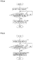
- the hybrid controller 31 performs a control to stop a power supply to the electric motor battery 34 when the charge amount C1 of the main battery 33 is equal to or less than a charge amount threshold T1. Specifically, the hybrid controller 31 stops a power supply to the electric motor battery 34 by opening (turning off) the switch 52a of the power distributor 5. The flow of this control process is described below with reference to a flowchart of FIG. 4 .
- the hybrid controller 31 transmits predetermined charging information regarding the charge amount of the electric motor battery 34 to the inverter control device 28 in order for the inverter control device 28 to perform a control to stop driving of the electric motor 22 based on the charge amount of the electric motor battery 34.
- the hybrid controller 31 transmits the predetermined charging information indicating that the charge amount C2 of the electric motor battery 34 has become a charge amount threshold T2 or less to the inverter control device 28 when the charge amount C2 of the electric motor battery 34 becomes equal to or less than the charge amount threshold T2. Then, the inverter control device 28 performs a control to stop driving of the electric motor 22 based on the predetermined charging information.
- the flow of this control process is described below with reference to a flowchart of FIG. 5 .
- step S1 the charge amounts of the main battery 33, the electric motor battery 34, and the house battery 35 are acquired based on the values of the currents detected by the first current sensor 28a, the second current sensor 51a, the third current sensor 51b, and the fourth current sensor 51c. Then, the process advances to step S2.
- step S2 it is determined whether or not the charge amount C1 of the main battery 33 is equal to or less than the charge amount threshold T1.
- the process advances to step S3.
- the charge amount C1 of the main battery 33 is greater than the charge amount threshold T1, the process operation in step S2 is repeated.
- step S3 the switch 52a of the power distributor 5 is opened such that a power supply to the electric motor battery 34 is stopped.
- step S11 the charge amounts of the main battery 33, the electric motor battery 34, and the house battery 35 are acquired based on the values of the currents detected by the first current sensor 28a, the second current sensor 51a, the third current sensor 51b, and the fourth current sensor 51c. Then, the process advances to step S12.
- step S12 it is determined whether or not the charge amount C2 of the electric motor battery 34 is equal to or less than the charge amount threshold T2.
- the process advances to step S13.
- the process operation in step S12 is repeated.
- step S13 the predetermined charging information is transmitted to the inverter control device 28. Consequently, the inverter control device 28 performs a control to stop driving of the electric motor 22 based on the predetermined charging information.
- the marine propulsion system 1a includes the hybrid controller 31 configured or programmed to perform a control to acquire the charge amount of at least one of the main battery 33, the electric motor battery 34, or the house battery 35 based on the first power P20, the first power P10, and the first power P30 supplied from the power source (generator 29) to the main battery 33, the electric motor battery 34, and the house battery 35, respectively, and the second power P21, the second power P11, and the second power P31 supplied from the main battery 33, the electric motor battery 34, and the house battery 35 to the devices in the marine vessel 100, respectively.
- the hybrid controller 31 configured or programmed to perform a control to acquire the charge amount of at least one of the main battery 33, the electric motor battery 34, or the house battery 35 based on the first power P20, the first power P10, and the first power P30 supplied from the power source (generator 29) to the main battery 33, the electric motor battery 34, and the house battery 35, respectively, and the second power P21, the second power P11, and
- the hybrid controller 31 acquires the charge amounts of the main battery 33, the electric motor battery 34, and the house battery 35 based on the first power P20, the first power P10, and the first power P30 and the second power P21, the second power P11, and the second power P31. That is, the charge amounts of the batteries (the main battery 33, the electric motor battery 34, and the house battery 35) that supply power to the devices in the marine vessel 100 are understood.
- the charge amounts of at least two of the main battery 33, the electric motor battery 34, or the house battery 35 necessary power management is performed according to the importance of a supply destination to which power is supplied.
- a predetermined control to ensure required power is performed in order to maintain driving of the marine vessel 100 until returning to port.
- the marine propulsion system 1a further includes the power distributor 5 connected to the main battery 33, the electric motor battery 34, and the house battery 35 to distribute the first power P20, the first power P10, and the first power P30 from the power source (generator 29) to the main battery 33, the electric motor battery 34, and the house battery 35, respectively, the main battery 33 and the house battery 35 supply the second power P21 and the second power P31 to the devices in the marine vessel 100 via the power distributor 5, and the electric motor battery 34 supplies the second power P11 to the electric motor 22 without interposition of the power distributor 5.
- the power distributor 5 at least the first power P20, the first power P30, the second power P21, and the second power P31 of the main battery 33 and the house battery 35 are acquired, and at least the first power P10 of the electric motor battery 34 is acquired. Therefore, the charge amounts of the main battery 33, the electric motor battery 34, and the house battery 35 that supply power to the devices in the marine vessel 100 are easily understood.
- the hybrid controller 31 is configured or programmed to perform a control to acquire the value of the current as the first power P10 supplied to the electric motor battery 34 based on the value of the current that flows from the power distributor 5 to the electric motor battery 34, acquire the value of the current as the second power P11 supplied to the electric motor 22 based on the value of the current that flows from the electric motor battery 34 to the electric motor 22, and acquire the charge amount of the electric motor battery 34 based on the value of the current as the first power P10 and the value of the current as the second power P11.
- the value of the current as the first power P10 supplied to the electric motor battery 34 is acquired based on the value of the current that flows from the power distributor 5 to the electric motor battery 34, and the value of the current as the second power P11 supplied to the electric motor 22 is acquired based on the value of the current that flows from the electric motor battery 34 to the electric motor 22. Consequently, the charge amount of the electric motor battery 34 is reliably understood based on the value of the current.
- the electric motor 22 includes the power converter (inverter control device 28) to convert the current as the second power P11 supplied from the electric motor battery 34 from a direct current to an alternating current
- the power converter includes the first current sensor 28a to detect the value of the current supplied to the electric motor 22
- the hybrid controller 31 is configured or programmed to perform a control to acquire the value of the current as the first power P10 supplied to the electric motor battery 34 based on the value of the current detected by the first current sensor 28a and acquire the charge amount of the electric motor battery 34 based on the value of the current as the first power P10 and the value of the current as the second power P11.
- the value of the current as the second power P11 supplied from the electric motor battery 34 is acquired by the first current sensor 28a of the power converter provided in the electric motor 22.
- the number of components is reduced, and the system structure is simplified.
- the marine propulsion system 1a further includes the converter 36 provided between the power distributor 5 and the electric motor battery 34 to boost the value of the voltage as the first power P10, and the second current sensor 51a provided on the power distributor 5 side relative to the converter 36 to detect the value of the current that flows between the power distributor 5 and the electric motor battery 34, and the hybrid controller 31 is configured or programmed to perform a control to acquire the value of the current as the first power P10 supplied to the electric motor battery 34 based on the value of the current detected by the second current sensor 51a and acquire the charge amount of the electric motor battery 34 based on the value of the current as the first power P10 and the value of the current as the second power P11.
- the value of the current as the first power P10 supplied to the electric motor battery 34 is acquired by the second current sensor 51a on the upstream side in the current flow direction relative to the converter 36, and thus as compared with a case in which the current sensor is provided on the downstream side relative to the converter 36, the system structure on the downstream side relative to the converter 36 is simplified.
- the power distributor 5 includes the second current sensor 51a, and the hybrid controller 31 is configured or programmed to perform a control to acquire the value of the current as the first power P10 supplied to the electric motor battery 34 based on the value of the current detected by the second current sensor 51a and acquire the charge amount of the electric motor battery 34 based on the value of the current as the first power P10 and the value of the current as the second power P11. Accordingly, the second current sensor 51a of the power distributor 5 acquires the value of the current as the first power P10 supplied to the electric motor battery 34.
- the number of components is reduced, and the system structure is simplified.
- the power distributor 5 includes the third current sensor 51b to detect the value of the current that flows between the power distributor 5 and the main battery 33, and the hybrid controller 31 is configured or programmed to perform a control to acquire the charge amount of the main battery 33 based on the value of the current as the first power P20 supplied to the main battery 33, detected by the third current sensor 51b, and the value of the current as the second power P21. Accordingly, the two second and third current sensors 51a and 51b are integrated into the power distributor 5, and thus the system structure is further simplified.
- the hybrid controller 31 is configured or programmed to perform a control to limit or stop a power supply to the electric motor battery 34 when the charge amount of the main battery 33 is equal to or less than the charge amount threshold. Accordingly, the amount of power supplied to the electric motor battery 34 having the power source (generator 29) common to the main battery 33 is reduced or reduced to zero, and thus the amount of power supplied to the main battery 33 is increased.
- the power distributor 5 includes the fourth current sensor 51c to detect the value of the current that flows between the power distributor 5 and the house battery 35, and the hybrid controller 31 is configured or programmed to perform a control to acquire the charge amount of the house battery 35 based on the value of the current as the first power P30 supplied to the house batter 35, detected by the fourth current sensor 51c, and the value of the current as the second power P31. Accordingly, the three second, third, and fourth current sensors 51a, 51b, and 51c are integrated into the power distributor 5, and thus the system structure is further simplified.
- the marine propulsion system 1a further includes the electric motor controller (inverter control device 28) to perform a control to limit or stop driving of the electric motor 22 based on the charge amount of the electric motor battery 34. Accordingly, when the charge amount of the electric motor battery 34 is not sufficient, the amount of power supplied to the electric motor 22 is reduced or reduced to 0, and thus the power consumption of the electric motor battery 34 is reduced.
- the electric motor controller inverter control device 28
- the power source includes the generator 29 mounted on the outboard motor 2 to generate power when the engine 21 is driven. Accordingly, the generator 29 generates power to supply the power to the main battery 33, the electric motor battery 34, and the house battery 35.
- the electric motor battery 34 is a lead storage battery. Accordingly, even in the lead storage battery (electric motor battery 34) that generally does not directly include a current sensor, the charge amount is understood based on the first power P10 supplied to the lead storage battery and the second power P11 supplied from the lead storage battery.
- an electric motor battery 234 is a lithium-ion battery, unlike the first preferred embodiment in which the electric motor battery 34 is a lead storage battery.
- the same or similar structures as those of the first preferred embodiment are denoted by the same reference numerals.
- a marine propulsion system 201a of a marine vessel 200 includes an outboard motor 2 and a marine power supply system 203.
- the marine power supply system 203 includes the electric motor battery 234, which is a lithium-ion battery.
- the electric motor battery 234 includes a fifth current sensor 234a.
- the fifth current sensor 234a detects both a value of a current as first power P10 supplied from a generator 29 to the electric motor battery 234 and a value of a current as second power P11 supplied from the electric motor battery 234 to an electric motor 22.
- the hybrid controller 31 performs a control to acquire the charge amount of the electric motor battery 234 based on the value of the current as the first power P10 supplied to the electric motor battery 234, detected by the fifth current sensor 234a and the value of the current as the second power P11.
- the electric motor battery 234 is a lithium-ion battery
- the lithium-ion battery includes the fifth current sensor 234a to detect the value of the current as the first power P10 supplied from the power source (generator 29) to the lithium-ion battery and the value of the current as the second power P11 supplied from the lithium-ion battery to the electric motor 22, and the hybrid controller 31 is configured or programmed to perform a control to acquire the charge amount of the lithium-ion battery based on the value of the current as the first power P10 supplied to the lithium-ion battery, detected by the fifth current sensor 234a, and the value of the current as the second power P11.
- both the value of the current as the first power P10 supplied to the lithium-ion battery and the value of the current as the second power P11 supplied from the lithium-ion battery to the electric motor 22 are detected by the fifth current sensor 234a generally provided in the lithium-ion battery. Therefore, as compared with a case in which a current sensor that detects the value of the current as the first power P10 supplied to the lithium-ion battery and a current sensor that detects the value of the current as the second power P11 supplied from the lithium-ion battery to the electric motor 22 are provided separately from the lithium-ion battery, the number of components is reduced, and the system structure is simplified.
- the marine vessel is preferably an outboard motor boat in each of the first and second preferred embodiments described above, the present teaching is not restricted to this. That is, the marine vessel may alternatively be a marine vessel other than an outboard motor boat.
- the marine vessel may be a marine vessel including an inboard motor, an inboard-outboard motor, or a jet propulsion device.
- main battery the electric motor battery, and the house battery are preferably provided in the hull in each of the first and second preferred embodiments described above, the present teaching is not restricted to this. That is, at least one of the main battery, the electric motor battery, or the house battery may alternatively be provided in the outboard motor.
- the electric motor battery is preferably a lead storage battery in the first preferred embodiment described above, and the electric motor battery is preferably a lithium-ion battery in the second preferred embodiment described above, the present teaching is not restricted to this.
- the electric motor battery may alternatively be a battery other than a lead storage battery and a lithium-ion battery, such as a lithium battery.
- the generator is preferably provided in the outboard motor in each of the first and second preferred embodiments described above, the present teaching is not restricted to this.
- the generator may alternatively be provided in the hull.
- the hybrid controller preferably acquires the charge amounts of all of the main battery, the electric motor battery, and the house battery in each of the first and second preferred embodiments described above, the present teaching is not restricted to this. In the present teaching, the hybrid controller may alternatively acquire the charge amounts of only one or two of the main battery, the electric motor battery, and the house battery.
- the present teaching is not restricted to this.
- the charge amounts of the main battery, the electric motor battery, and the house battery may alternatively be acquired based on a value of a voltage detected by a voltmeter that measures the open end voltage of a battery.
- the value of the voltage as the first power supplied to the electric motor battery may be detected by the converter.
- a control is preferably performed to stop a power supply to the electric motor battery when the charge amount of the main battery is equal to or less than the predetermined charge amount threshold in each of the first and second preferred embodiments described above, the present teaching is not restricted to this.
- a control may alternatively be performed to limit a power supply to the electric motor battery.
- a control is preferably performed to stop driving of the electric motor when the charge amount of the electric motor battery is equal to or less than the predetermined charge amount threshold in each of the first and second preferred embodiments described above, the present teaching is not restricted to this. In the present teaching, when the charge amount of the electric motor battery is equal to or less than the predetermined charge amount threshold, a control may alternatively be performed to limit driving of the electric motor.
- process operations performed by the hybrid controller are described using flowcharts in a flow-driven manner in which processes are performed in order along a process flow for the convenience of illustration in each of the first and second preferred embodiments described above, the present teaching is not restricted to this.
- the process operations performed by the hybrid controller may alternatively be performed in an event-driven manner in which the processes are performed on an event basis.
- the process operations performed by the hybrid controller may be performed in a complete event-driven manner or in a combination of an event-driven manner and a flow-driven manner.
Landscapes
- Engineering & Computer Science (AREA)
- Mechanical Engineering (AREA)
- Power Engineering (AREA)
- Chemical & Material Sciences (AREA)
- Combustion & Propulsion (AREA)
- Transportation (AREA)
- Ocean & Marine Engineering (AREA)
- Sustainable Development (AREA)
- Sustainable Energy (AREA)
- Life Sciences & Earth Sciences (AREA)
- General Engineering & Computer Science (AREA)
- Charge And Discharge Circuits For Batteries Or The Like (AREA)
- Electric Propulsion And Braking For Vehicles (AREA)
- Control Of Charge By Means Of Generators (AREA)
Abstract
Description
- The present invention relates to a marine propulsion system and a marine power supply system.
- A marine propulsion system and a marine power supply system, both of which supply power to a marine propulsion unit including an engine and an electric motor, are known in general. Such a marine propulsion system and a marine power supply system are disclosed in
JP 2017-218016 A -
JP 2017-218016 A JP 2017-218016 A - However, conventional marine vessels including the marine vessel disclosed in
JP 2017-218016 A - It is an object of the present invention to provide a marine propulsion system and a marine power supply system that understand the charge amounts of batteries that supply power to devices in a marine vessel. According to the present invention, said object is solved by a marine propulsion system and a marine power supply system having the features of
independent claims 1 and 14. Preferred embodiments are laid down in the dependent claims. - A marine propulsion system according to a preferred embodiment includes a marine propulsion unit including a propulsion generator, an engine configured to drive the propulsion generator, and an electric motor configured to drive the propulsion generator, a first battery configured to supply power to a starter configured to start the engine, a second battery configured to supply power to the electric motor, a third battery configured to supply power to at least one of a plurality of devices in a marine vessel excluding the starter and the electric motor, and a charge amount acquisition controller configured or programmed to perform a control to acquire a charge amount of at least one of the first battery, the second battery, or the third battery based on first power supplied from a power source to the first battery, the second battery, and the third battery, and second power supplied from the first battery, the second battery, and the third battery to devices in the marine vessel.
- A marine propulsion system according to a preferred embodiment includes the charge amount acquisition controller configured or programmed to perform a control to acquire the charge amount of at least one of the first battery, the second battery, or the third battery based on the first power supplied from the power source to the first battery, the second battery, and the third battery, and the second power supplied from the first battery, the second battery, and the third battery to the devices in the marine vessel. Accordingly, the charge amount acquisition controller acquires the charge amount of at least one of the first battery, the second battery, and the third battery based on the first power and the second power. That is, the charge amount of the battery (at least one of the first battery, the second battery, or the third battery) that supplies power to the devices in the marine vessel is understood. When the charge amounts of at least two of the first battery, the second battery, or the third battery are understood, necessary power management is performed according to the importance of a supply destination to which power is supplied. When the charge amounts of the batteries (the first battery and the second battery) used to drive the marine propulsion unit are understood, a predetermined control to ensure required power is performed in order to maintain driving of the marine vessel until returning to port.
- A marine propulsion system according to a preferred embodiment preferably further includes a power distributor connected to the first battery, the second battery, and the third battery and configured to distribute the first power from the power source to the first battery, the second battery, and the third battery, the first battery and the third battery are preferably configured to supply the second power to the devices in the marine vessel via the power distributor, and the second battery is preferably configured to supply the second power to the electric motor without interposition of the power distributor. Accordingly, in the power distributor, at least the first power and the second power of the first battery and the third battery are acquired, and at least the first power of the second battery is acquired. Therefore, the charge amounts of the first battery, the second battery, and the third battery that supply power to the devices in the marine vessel are easily understood.
- In such a case, the charge amount acquisition controller is preferably configured or programmed to perform a control to acquire a value of a current as the first power supplied to the second battery based on a value of a current that flows from the power distributor to the second battery, acquire a value of a current as the second power supplied to the electric motor based on a value of a current that flows from the second battery to the electric motor, and acquire the charge amount of the second battery based on the value of the current as the first power and the value of the current as the second power. Accordingly, the value of the current as the first power supplied to the second battery is acquired based on the value of the current that flows from the power distributor to the second battery, and the value of the current as the second power supplied to the electric motor is acquired based on the value of the current that flows from the second battery to the electric motor. Consequently, the charge amount of the second battery is reliably understood based on the value of the current.
- In a marine propulsion system including the charge amount acquisition controller configured or programmed to acquire the value of the current as the first power supplied to the second battery based on the value of the current that flows from the power distributor to the second battery and acquire the charge amount of the second battery, the electric motor preferably includes a power converter configured to convert the current as the second power supplied from the second battery from a direct current to an alternating current, the power converter preferably includes a first current sensor configured to detect the value of the current supplied to the electric motor, and the charge amount acquisition controller is preferably configured or programmed to perform a control to acquire the value of the current as the first power supplied to the second battery based on the value of the current detected by the first current sensor and acquire the charge amount of the second battery based on the value of the current as the first power and the value of the current as the second power. Accordingly, the value of the current as the second power supplied from the second battery is acquired by the first current sensor of the power converter provided in the electric motor. Thus, as compared with a case in which a dedicated current sensor is provided to acquire the value of the current as the second power, the number of components is reduced, and the system structure is simplified.
- A marine propulsion system including the charge amount acquisition controller configured or programmed to acquire the value of the current as the first power supplied to the second battery based on the value of the current that flows from the power distributor to the second battery and acquire the charge amount of the second battery preferably further includes a converter provided between the power distributor and the second battery and configured to boost a value of a voltage as the first power, and a second current sensor provided on a power distributor side relative to the converter and configured to detect a value of a current that flows between the power distributor and the second battery. The charge amount acquisition controller is preferably configured or programmed to perform a control to acquire the value of the current as the first power supplied to the second battery based on the value of the current detected by the second current sensor and acquire the charge amount of the second battery based on the value of the current as the first power and the value of the current as the second power. Accordingly, the value of the current as the first power supplied to the second battery is acquired by the second current sensor on the upstream side in the current flow direction relative to the converter, and thus as compared with a case in which the current sensor is provided on the downstream side relative to the converter, the system structure on the downstream side relative to the converter is simplified.
- In such a case, the power distributor preferably includes the second current sensor, and the charge amount acquisition controller is preferably configured or programmed to perform a control to acquire the value of the current as the first power supplied to the second battery based on the value of the current detected by the second current sensor and acquire the charge amount of the second battery based on the value of the current as the first power and the value of the current as the second power. Accordingly, the second current sensor of the power distributor acquires the value of the current as the first power supplied to the second battery. Thus, as compared with a case in which a dedicated current sensor is provided to acquire the value of the current as the first power, the number of components is reduced, and the system structure is simplified.
- In a marine propulsion system including the power distributor including the second current sensor, the power distributor preferably includes a third current sensor configured to detect a value of a current that flows between the power distributor and the first battery, and the charge amount acquisition controller is preferably configured or programmed to perform a control to acquire the charge amount of the first battery based on the value of the current as the first power supplied to the first battery, detected by the third current sensor, and the value of the current as the second power. Accordingly, the two second and third current sensors are integrated into the power distributor, and thus the system structure is further simplified.
- In a marine propulsion system including the power distributor including the third current sensor, the charge amount acquisition controller is preferably configured or programmed to perform a control to limit or stop a power supply to the second battery when the charge amount of the first battery is equal to or less than a charge amount threshold. Accordingly, the amount of power supplied to the second battery having the power source common to the first battery is reduced or reduced to zero, and thus the amount of power supplied to the first battery is increased.
- In a marine propulsion system including the power distributor including the third current sensor, the power distributor preferably includes a fourth current sensor configured to detect a value of a current that flows between the power distributor and the third battery, and the charge amount acquisition controller is preferably configured or programmed to perform a control to acquire the charge amount of the third battery based on the value of the current as the first power supplied to the third battery, detected by the fourth current sensor, and the value of the current as the second power. Accordingly, the three second, third, and fourth current sensors are integrated into the power distributor, and thus the system structure is further simplified.
- A marine propulsion system according to a preferred embodiment preferably further includes an electric motor controller configured or programmed to perform a control to limit or stop driving of the electric motor based on the charge amount of the second battery. Accordingly, when the charge amount of the second battery is not sufficient, the amount of power supplied to the electric motor is reduced or reduced to 0, and thus the power consumption of the second battery is reduced.
- In such a case, the power source preferably includes a generator mounted on the marine propulsion unit and configured to generate power when the engine is driven. Accordingly, the generator generates power to supply the power to the first battery, the second battery, and the third battery.
- In a marine propulsion system according to a preferred embodiment, the second battery is preferably a lead storage battery. Accordingly, even in the lead storage battery that generally does not directly include a current sensor, the charge amount is understood based on the first power supplied to the lead storage battery and the second power supplied from the lead storage battery.
- In a marine propulsion system according to a preferred embodiment, the second battery is preferably a lithium-ion battery, the lithium-ion battery preferably includes a fifth current sensor configured to detect a value of a current as the first power supplied from the power source to the lithium-ion battery and a value of a current as the second power supplied from the lithium-ion battery to the electric motor, and the charge amount acquisition controller is preferably configured or programmed to perform a control to acquire a charge amount of the lithium-ion battery based on the value of the current as the first power supplied to the lithium-ion battery, detected by the fifth current sensor, and the value of the current as the second power. Accordingly, both the value of the current as the first power supplied to the lithium-ion battery and the value of the current as the second power supplied from the lithium-ion battery to the electric motor are detected by the fifth current sensor generally provided in the lithium-ion battery. Therefore, as compared with a case in which a current sensor that detects the value of the current as the first power supplied to the lithium-ion battery and a current sensor that detects the value of the current as the second power supplied from the lithium-ion battery to the electric motor are provided separately from the lithium-ion battery, the number of components is reduced, and the system structure is simplified.
- The above and other elements, features, steps, characteristics and advantages of preferred embodiments will become more apparent from the following detailed description of the preferred embodiments with reference to the attached drawings.
-
-
FIG. 1 is a perspective view schematically showing a marine vessel including a marine propulsion system according to a first preferred embodiment. -
FIG. 2 is a side view illustrating the structure of an outboard motor according to the first preferred embodiment. -
FIG. 3 is a block diagram showing the structure of the marine vessel according to the first preferred embodiment. -
FIG. 4 is a flowchart showing a control process performed when the charge amount of a main battery of the marine propulsion system is reduced according to the first preferred embodiment. -
FIG. 5 is a flowchart showing a control process performed when the charge amount of an electric motor battery of the marine propulsion system is reduced according to the first preferred embodiment. -
FIG. 6 is a block diagram showing the structure of a marine vessel according to a second preferred embodiment. - Preferred embodiments are hereinafter described with reference to the drawings.
- The structure of a
marine propulsion system 1a according to a first preferred embodiment is now described with reference toFIGS. 1 to 3 . Themarine propulsion system 1a is a component of amarine vessel 100. In the figures, arrow FWD represents the forward movement direction of themarine vessel 100, and arrow BWD represents the reverse movement direction of themarine vessel 100. - As shown in
FIG. 1 , themarine vessel 100 includes ahull 1 and themarine propulsion system 1a. - The
marine propulsion system 1a includes anoutboard motor 2 and a marinepower supply system 3. Furthermore, a steering 4 (seeFIG. 2 ) is provided on theoutboard motor 2. Theoutboard motor 2 is an example of a "marine propulsion unit". - The
marine vessel 100 is an outboard motor boat. The marinepower supply system 3 is a power supply system that supplies power to theoutboard motor 2. - The
marine propulsion system 1a according to the first preferred embodiment performs a control to acquire the charge amounts of amain battery 33, anelectric motor battery 34, and ahouse battery 35 based on first power P20, first power P10, and first power P30 (seeFIG. 3 ) supplied (input) from agenerator 29 of theoutboard motor 2 to themain battery 33, theelectric motor battery 34, and thehouse battery 35, and second power P21, second power P11, and second power P31 (seeFIG. 3 ) supplied (output) from themain battery 33, theelectric motor battery 34, and thehouse battery 35 to devices in themarine vessel 100 with ahybrid controller 31 of the marinepower supply system 3. The details are described below. In the description, the "first power (P10, P20, and P30)" refers to power input to each battery, and the "second power (P11, P21, and P31)" refers to power output from each battery. Thehybrid controller 31 is an example of a "charge amount acquisition controller". Thegenerator 29 is an example of a "power source". Themain battery 33 is an example of a "first battery". Theelectric motor battery 34 is an example of a "second battery". Thehouse battery 35 is an example of a "third battery". - As shown in
FIG. 2 , theoutboard motor 2 is attached to thehull 1 via thesteering 4. Theoutboard motor 2 includes anengine 21, anelectric motor 22, apropeller 23, an engine electronic control unit (ECU) 24, astarter motor 25, a clutch 26, and ashift actuator 27. Thepropeller 23 is an example of a "propulsion generator". Thestarter motor 25 is an example of a "starter". - As shown in
FIG. 3 , theoutboard motor 2 includes aninverter control device 28 including a firstcurrent sensor 28a and thegenerator 29. Theinverter control device 28 is an example of a "power converter" or an "electric motor controller". - The
engine 21 drives thepropeller 23. Specifically, theengine 21 is an internal combustion engine driven by explosive combustion of gasoline, light oil, or the like. Theengine 21 is connected to thepropeller 23 via adrive shaft 21a, the clutch 26, and apropeller shaft 23a. A driving force (rotational force) is transmitted from theengine 21 to thepropeller 23 such that thepropeller 23 rotates, and the marine vessel 100 (hull 1) is propelled. - The
electric motor 22 drives thepropeller 23. Theelectric motor 22 is a motor. Theelectric motor 22 is driven using power converted by theinverter control device 28. Theelectric motor 22 is connected to thepropeller 23 via ashaft 22a, the clutch 26, and thepropeller shaft 23a. A driving force (rotational force) is transmitted from theelectric motor 22 to thepropeller 23 such that thepropeller 23 rotates, and the marine vessel 100 (hull 1) is propelled. Theelectric motor 22 drives and assists the clutch 26 (propeller shaft 23a) when the clutch 26 performs a switching operation described below. Thepropeller 23 is positioned in the water, and rotates to generate a propulsive force. - As shown in
FIG. 3 , theengine ECU 24 communicates with thehybrid controller 31 described below and theinverter control device 28. For example, theengine ECU 24 transmits and receives information and command signals to and from thehybrid controller 31 and theinverter control device 28 by controller area network (CAN) communication. Theengine ECU 24 is connected to themain battery 33 via apower distributor 5. Theengine ECU 24 operates using power from themain battery 33. InFIG. 3 , dotted lines are shown as communication lines, and solid lines are shown as power lines. The communication lines may represent wired communication or wireless communication. - The
starter motor 25 starts theengine 21. Specifically, thestarter motor 25 is connected to themain battery 33 via thepower distributor 5. Thestarter motor 25 is driven using the second power P21 from themain battery 33. Thestarter motor 25 rotates (cranks) a crankshaft of theengine 21 based on a command from the engine ECU 24 (hybrid controller 31). Theengine 21 is cranked by thestarter motor 25, fuel is supplied into theengine 21 by a fuel supplier (not shown), and the fuel in theengine 21 is ignited by an igniter (not shown) to start theengine 21. The second power P21 is supplied from themain battery 33 to the fuel supplier and the igniter. - As shown in
FIG. 2 , the clutch 26 is provided between theengine 21 and thepropeller 23, and switches between a state in which a rotational force is transmitted from theengine 21 to the propeller 23 (a state in which "the shift position is at a forward movement position" or a state in which "the shift position is at a reverse movement position") and a state in which a rotational force is not transmitted from theengine 21 to the propeller 23 (a state in which "the shift position is at a neutral position") (performs the switching operation). The clutch 26 is a dog clutch, for example. The clutch 26 may be a friction clutch. Theelectric motor 22 rotates a gear in the clutch 26 or thepropeller 23 such that the rotation of the gear in the clutch 26 or thepropeller 23 is synchronized with rotation of thedrive shaft 21a connected to theengine 21 before the clutch 26 performs the switching operation. The rotation speed of the gear in the clutch 26 and the rotation speed of thedrive shaft 21a are close to each other, and thus the impact in the clutch 26 during the switching operation of the clutch 26 is reduced. - The
shift actuator 27 moves the shift position between the forward movement position and the neutral position and moves the shift position between the reverse movement position and the neutral position based on commands from thehybrid controller 31. - The
inverter control device 28 performs a control to convert a current as the second power P11 supplied from theelectric motor battery 34 from a direct current to an alternating current and performs a control to supply AC power to theelectric motor 22 that drives thepropeller 23, based on a command from at least one of thehybrid controller 31 or theengine ECU 24. - The
inverter control device 28 is provided with the firstcurrent sensor 28a that detects a value of a current that flows from theelectric motor battery 34 to the inverter control device 28 (a value of a current as the second power P11 supplied from theelectric motor battery 34 to the electric motor 22). The value of the current as the second power P11 detected by the firstcurrent sensor 28a is acquired by thehybrid controller 31. - The
engine 21 is driven such that thegenerator 29 generates power and inputs the generated power to thepower distributor 5. The generated power is supplied to themain battery 33, theelectric motor battery 34, and thehouse battery 35 via thepower distributor 5. - As shown in
FIG. 3 , the marinepower supply system 3 includes thehybrid controller 31, a marinevessel maneuvering unit 32, themain battery 33, theelectric motor battery 34, thehouse battery 35, aconverter 36, an externalconnection power supply 37, and thepower distributor 5. - The
hybrid controller 31, the marinevessel maneuvering unit 32, themain battery 33, theelectric motor battery 34, thehouse battery 35, theconverter 36, the externalconnection power supply 37, and thepower distributor 5 are provided in thehull 1, for example. - The marine
vessel maneuvering unit 32 includes aremote control 32a, ajoystick 32b, and a marinevessel maneuvering controller 32c. Theremote control 32a and thejoystick 32b receive input operations by an operator and transmit operation signals based on the received input operations to the marinevessel maneuvering controller 32c. The marinevessel maneuvering controller 32c includes a remote control ECU, and is configured or programmed to transmit the operation signals to theengine ECU 24 and thesteering 4 via thehybrid controller 31. - The first power P20 is supplied (input) from the
generator 29 or an external power supply (not shown) connected to the externalconnection power supply 37 to themain battery 33 via thepower distributor 5. Themain battery 33 supplies (outputs) the second power P21 to thestarter motor 25 that starts theengine 21 via thepower distributor 5. Themain battery 33 is a lead storage battery or a lithium-ion battery. - The first power P10 is supplied (input) from the
generator 29 or the external power supply (not shown) connected to the externalconnection power supply 37 to theelectric motor battery 34 via thepower distributor 5. Theelectric motor battery 34 supplies (outputs) the second power P11 to the electric motor 22 (inverter control device 28) without interposition of thepower distributor 5. Theelectric motor battery 34 is a lead storage battery. - The first power P30 is supplied (input) from the
generator 29 or the external power supply (not shown) connected to the externalconnection power supply 37 to thehouse battery 35 via thepower distributor 5. Thehouse battery 35 supplies (outputs) the second power P31 to at least one (a device in a house) of devices in themarine vessel 100 excluding theelectric motor 22 and thestarter motor 25. Thehouse battery 35 is a lead storage battery or a lithium-ion battery. - That is, the first power P20 and the first power P30 are input to the
main battery 33 and thehouse battery 35 via thepower distributor 5, and the second power P21 and the second power P31 are output from themain battery 33 and thehouse battery 35 via thepower distributor 5. On the other hand, the first power P10 is input to theelectric motor battery 34 via thepower distributor 5, and the second power P11 is output from theelectric motor battery 34 without interposition of thepower distributor 5. - The
converter 36 is provided between thepower distributor 5 and theelectric motor battery 34. Theconverter 36 boosts a value of a voltage as the first power P10 supplied (output) to theelectric motor battery 34 via thepower distributor 5. For example, theconverter 36 boosts a voltage of 12V to a voltage of 36 V or 48 V. - The external
connection power supply 37 is connectable to the external power supply (commercial power supply) outside themarine vessel 100. The externalconnection power supply 37 is connected to thepower distributor 5 and supplies (inputs) power from the external power supply outside themarine vessel 100 to thepower distributor 5. The externalconnection power supply 37 converts a current from an alternating current to a direct current and supplies the direct current to thepower distributor 5. - The
power distributor 5 is connected to themain battery 33, theelectric motor battery 34, and thehouse battery 35, and supplies (distributes) the first power P20, the first power P10, and the first power P30 from thegenerator 29 to themain battery 33, theelectric motor battery 34 and thehouse battery 35, respectively. - Specifically, the
power distributor 5 includes a secondcurrent sensor 51a, a thirdcurrent sensor 51b, a fourthcurrent sensor 51c, aswitch 52a provided in the secondcurrent sensor 51a, aswitch 52b provided in the thirdcurrent sensor 51b, and aswitch 52c provided in the fourthcurrent sensor 51c. - The second
current sensor 51a is provided on thepower distributor 5 side relative to theconverter 36, and detects a value of a current that flows between thepower distributor 5 and theelectric motor battery 34. That is, the secondcurrent sensor 51a detects the value of the current as the first power P10 supplied (input) from thegenerator 29 to theelectric motor battery 34 via thepower distributor 5. - The third
current sensor 51b detects values of currents that flow between thepower distributor 5 and themain battery 33. That is, the thirdcurrent sensor 51b detects the value of the current as the first power P20 supplied (input) from thegenerator 29 to themain battery 33 via thepower distributor 5. Furthermore, the thirdcurrent sensor 51b detects the value of the current as the second power P21 supplied (output) from themain battery 33 to thestarter motor 25 via thepower distributor 5. - The fourth
current sensor 51c detects values of currents that flow between thepower distributor 5 and thehouse battery 35. That is, the fourthcurrent sensor 51c detects the value of the current as the first power P30 supplied (input) from thepower distributor 5 to thehouse battery 35. Furthermore, the fourthcurrent sensor 51c detects the value of the current as the second power P31 supplied (output) from thehouse battery 35 to a predetermined device in themarine vessel 100 via thepower distributor 5. - The values of the currents detected by the second
current sensor 51a, the thirdcurrent sensor 51b, and the fourthcurrent sensor 51c are acquired by thehybrid controller 31. - The
switch 52a opens and closes an electric circuit between thepower distributor 5 and theelectric motor battery 34. The secondcurrent sensor 51a is provided in the electric circuit between theswitch 52a and theelectric motor battery 34. - The
switch 52b opens and closes an electric circuit between thepower distributor 5 and themain battery 33. The thirdcurrent sensor 51b is provided in the electric circuit between theswitch 52b and themain battery 33. - The
switch 52c opens and closes an electric circuit between thepower distributor 5 and thehouse battery 35. The fourthcurrent sensor 51c is provided in the electric circuit between theswitch 52c and thehouse battery 35. - The open states and the closed states of the
switch 52a, theswitch 52b, and theswitch 52c are switched by thehybrid controller 31. - The
hybrid controller 31 includes a control circuit that controls both driving of theengine 21 in theoutboard motor 2 and driving of theelectric motor 22 in theoutboard motor 2. For example, thehybrid controller 31 includes a processor that performs an arithmetic process, such as a CPU. - The
hybrid controller 31 acquires the value of the current as the first power P10 supplied (input) to theelectric motor battery 34 based on the value of the current detected by the secondcurrent sensor 51a. Furthermore, thehybrid controller 31 acquires the value of the current as the second power P11 supplied (output) to theelectric motor 22 based on the value of the current detected by the firstcurrent sensor 28a. - Then, the
hybrid controller 31 performs a control to acquire the charge amount of theelectric motor battery 34 based on the value of the current as the first power P10 detected by the secondcurrent sensor 51a and the value of the current as the second power P11 detected by the firstcurrent sensor 28a. For example, thehybrid controller 31 acquires the charge amount of theelectric motor battery 34 by adding a value (charging power) obtained by multiplying a value of a current as the first power P10 (power input to the motor battery 34) by a value of the voltage of themotor battery 34 to a value obtained by subtracting a value (consumed power) obtained by multiplying a value of a current as the second power P11 (power output from the motor battery 34) by a value of the voltage of themotor battery 34 from a value of power based on a fully charged state. - The
hybrid controller 31 acquires the value of the current as the first power P20 supplied (input) to themain battery 33 based on the value of the current detected by the thirdcurrent sensor 51b. Furthermore, thehybrid controller 31 acquires the value of the current as the second power P21 supplied (output) from themain battery 33 to thestarter motor 25 based on the value of the current detected by the thirdcurrent sensor 51b. - Then, the
hybrid controller 31 performs a control to acquire the charge amount of themain battery 33 based on the value of the current as the first power P20 detected by the thirdcurrent sensor 51b and the value of the current as the second power P21 detected by the thirdcurrent sensor 51b. - The
hybrid controller 31 acquires the value of the current as the first power P30 supplied (input) to thehouse battery 35 based on the value of the current detected by the fourthcurrent sensor 51c. Furthermore, thehybrid controller 31 acquires the value of the current as the second power P31 supplied (output) from thehouse battery 35 to the predetermined device in themarine vessel 100 based on the value of the current detected by the fourthcurrent sensor 51c. - Then, the
hybrid controller 31 performs a control to acquire the charge amount of thehouse battery 35 based on the value of the current as the first power P30 detected by the fourthcurrent sensor 51c and the value of the current as the second power P31 detected by the fourthcurrent sensor 51c. - The
hybrid controller 31 performs a control to stop a power supply to theelectric motor battery 34 when the charge amount C1 of themain battery 33 is equal to or less than a charge amount threshold T1. Specifically, thehybrid controller 31 stops a power supply to theelectric motor battery 34 by opening (turning off) theswitch 52a of thepower distributor 5. The flow of this control process is described below with reference to a flowchart ofFIG. 4 . - The
hybrid controller 31 transmits predetermined charging information regarding the charge amount of theelectric motor battery 34 to theinverter control device 28 in order for theinverter control device 28 to perform a control to stop driving of theelectric motor 22 based on the charge amount of theelectric motor battery 34. - For example, the
hybrid controller 31 transmits the predetermined charging information indicating that the charge amount C2 of theelectric motor battery 34 has become a charge amount threshold T2 or less to theinverter control device 28 when the charge amount C2 of theelectric motor battery 34 becomes equal to or less than the charge amount threshold T2. Then, theinverter control device 28 performs a control to stop driving of theelectric motor 22 based on the predetermined charging information. The flow of this control process is described below with reference to a flowchart ofFIG. 5 . - The control process executed by the
hybrid controller 31 when the charge amount of themain battery 33 is reduced is now described with reference to the flowchart ofFIG. 4 . - In step S1, the charge amounts of the
main battery 33, theelectric motor battery 34, and thehouse battery 35 are acquired based on the values of the currents detected by the firstcurrent sensor 28a, the secondcurrent sensor 51a, the thirdcurrent sensor 51b, and the fourthcurrent sensor 51c. Then, the process advances to step S2. - In step S2, it is determined whether or not the charge amount C1 of the
main battery 33 is equal to or less than the charge amount threshold T1. When the charge amount C1 of themain battery 33 is equal to or less than the charge amount threshold T1, the process advances to step S3. When the charge amount C1 of themain battery 33 is greater than the charge amount threshold T1, the process operation in step S2 is repeated. - In step S3, the
switch 52a of thepower distributor 5 is opened such that a power supply to theelectric motor battery 34 is stopped. - The control process executed by the
hybrid controller 31 when the charge amount of theelectric motor battery 34 is reduced is now described with reference to the flowchart ofFIG. 5 . - In step S11, the charge amounts of the
main battery 33, theelectric motor battery 34, and thehouse battery 35 are acquired based on the values of the currents detected by the firstcurrent sensor 28a, the secondcurrent sensor 51a, the thirdcurrent sensor 51b, and the fourthcurrent sensor 51c. Then, the process advances to step S12. - In step S12, it is determined whether or not the charge amount C2 of the
electric motor battery 34 is equal to or less than the charge amount threshold T2. When the charge amount C2 of theelectric motor battery 34 is equal to or less than the charge amount threshold T2, the process advances to step S13. When the charge amount C2 of theelectric motor battery 34 is greater than the charge amount threshold T2, the process operation in step S12 is repeated. - In step S13, the predetermined charging information is transmitted to the
inverter control device 28. Consequently, theinverter control device 28 performs a control to stop driving of theelectric motor 22 based on the predetermined charging information. - According to the first preferred embodiment, the following advantageous effects are achieved.
- According to the first preferred embodiment, the
marine propulsion system 1a includes thehybrid controller 31 configured or programmed to perform a control to acquire the charge amount of at least one of themain battery 33, theelectric motor battery 34, or thehouse battery 35 based on the first power P20, the first power P10, and the first power P30 supplied from the power source (generator 29) to themain battery 33, theelectric motor battery 34, and thehouse battery 35, respectively, and the second power P21, the second power P11, and the second power P31 supplied from themain battery 33, theelectric motor battery 34, and thehouse battery 35 to the devices in themarine vessel 100, respectively. Accordingly, thehybrid controller 31 acquires the charge amounts of themain battery 33, theelectric motor battery 34, and thehouse battery 35 based on the first power P20, the first power P10, and the first power P30 and the second power P21, the second power P11, and the second power P31. That is, the charge amounts of the batteries (themain battery 33, theelectric motor battery 34, and the house battery 35) that supply power to the devices in themarine vessel 100 are understood. When the charge amounts of at least two of themain battery 33, theelectric motor battery 34, or thehouse battery 35 is understood, necessary power management is performed according to the importance of a supply destination to which power is supplied. When the charge amounts of the batteries (themain battery 33 and the electric motor battery 34) used to drive thepropeller 23 are understood, a predetermined control to ensure required power is performed in order to maintain driving of themarine vessel 100 until returning to port. - According to the first preferred embodiment, the
marine propulsion system 1a further includes thepower distributor 5 connected to themain battery 33, theelectric motor battery 34, and thehouse battery 35 to distribute the first power P20, the first power P10, and the first power P30 from the power source (generator 29) to themain battery 33, theelectric motor battery 34, and thehouse battery 35, respectively, themain battery 33 and thehouse battery 35 supply the second power P21 and the second power P31 to the devices in themarine vessel 100 via thepower distributor 5, and theelectric motor battery 34 supplies the second power P11 to theelectric motor 22 without interposition of thepower distributor 5. Accordingly, in thepower distributor 5, at least the first power P20, the first power P30, the second power P21, and the second power P31 of themain battery 33 and thehouse battery 35 are acquired, and at least the first power P10 of theelectric motor battery 34 is acquired. Therefore, the charge amounts of themain battery 33, theelectric motor battery 34, and thehouse battery 35 that supply power to the devices in themarine vessel 100 are easily understood. - According to the first preferred embodiment, the
hybrid controller 31 is configured or programmed to perform a control to acquire the value of the current as the first power P10 supplied to theelectric motor battery 34 based on the value of the current that flows from thepower distributor 5 to theelectric motor battery 34, acquire the value of the current as the second power P11 supplied to theelectric motor 22 based on the value of the current that flows from theelectric motor battery 34 to theelectric motor 22, and acquire the charge amount of theelectric motor battery 34 based on the value of the current as the first power P10 and the value of the current as the second power P11. Accordingly, the value of the current as the first power P10 supplied to theelectric motor battery 34 is acquired based on the value of the current that flows from thepower distributor 5 to theelectric motor battery 34, and the value of the current as the second power P11 supplied to theelectric motor 22 is acquired based on the value of the current that flows from theelectric motor battery 34 to theelectric motor 22. Consequently, the charge amount of theelectric motor battery 34 is reliably understood based on the value of the current. - According to the first preferred embodiment, the
electric motor 22 includes the power converter (inverter control device 28) to convert the current as the second power P11 supplied from theelectric motor battery 34 from a direct current to an alternating current, the power converter includes the firstcurrent sensor 28a to detect the value of the current supplied to theelectric motor 22, and thehybrid controller 31 is configured or programmed to perform a control to acquire the value of the current as the first power P10 supplied to theelectric motor battery 34 based on the value of the current detected by the firstcurrent sensor 28a and acquire the charge amount of theelectric motor battery 34 based on the value of the current as the first power P10 and the value of the current as the second power P11. Accordingly, the value of the current as the second power P11 supplied from theelectric motor battery 34 is acquired by the firstcurrent sensor 28a of the power converter provided in theelectric motor 22. Thus, as compared with a case in which a dedicated current sensor is provided to acquire the value of the current as the second power P11, the number of components is reduced, and the system structure is simplified. - According to the first preferred embodiment, the
marine propulsion system 1a further includes theconverter 36 provided between thepower distributor 5 and theelectric motor battery 34 to boost the value of the voltage as the first power P10, and the secondcurrent sensor 51a provided on thepower distributor 5 side relative to theconverter 36 to detect the value of the current that flows between thepower distributor 5 and theelectric motor battery 34, and thehybrid controller 31 is configured or programmed to perform a control to acquire the value of the current as the first power P10 supplied to theelectric motor battery 34 based on the value of the current detected by the secondcurrent sensor 51a and acquire the charge amount of theelectric motor battery 34 based on the value of the current as the first power P10 and the value of the current as the second power P11. Accordingly, the value of the current as the first power P10 supplied to theelectric motor battery 34 is acquired by the secondcurrent sensor 51a on the upstream side in the current flow direction relative to theconverter 36, and thus as compared with a case in which the current sensor is provided on the downstream side relative to theconverter 36, the system structure on the downstream side relative to theconverter 36 is simplified. - According to the first preferred embodiment, the
power distributor 5 includes the secondcurrent sensor 51a, and thehybrid controller 31 is configured or programmed to perform a control to acquire the value of the current as the first power P10 supplied to theelectric motor battery 34 based on the value of the current detected by the secondcurrent sensor 51a and acquire the charge amount of theelectric motor battery 34 based on the value of the current as the first power P10 and the value of the current as the second power P11. Accordingly, the secondcurrent sensor 51a of thepower distributor 5 acquires the value of the current as the first power P10 supplied to theelectric motor battery 34. Thus, as compared with a case in which a dedicated current sensor is provided to acquire the value of the current as the first power P10, the number of components is reduced, and the system structure is simplified. - According to the first preferred embodiment, the
power distributor 5 includes the thirdcurrent sensor 51b to detect the value of the current that flows between thepower distributor 5 and themain battery 33, and thehybrid controller 31 is configured or programmed to perform a control to acquire the charge amount of themain battery 33 based on the value of the current as the first power P20 supplied to themain battery 33, detected by the thirdcurrent sensor 51b, and the value of the current as the second power P21. Accordingly, the two second and thirdcurrent sensors power distributor 5, and thus the system structure is further simplified. - According to the first preferred embodiment, the
hybrid controller 31 is configured or programmed to perform a control to limit or stop a power supply to theelectric motor battery 34 when the charge amount of themain battery 33 is equal to or less than the charge amount threshold. Accordingly, the amount of power supplied to theelectric motor battery 34 having the power source (generator 29) common to themain battery 33 is reduced or reduced to zero, and thus the amount of power supplied to themain battery 33 is increased. - According to the first preferred embodiment, the
power distributor 5 includes the fourthcurrent sensor 51c to detect the value of the current that flows between thepower distributor 5 and thehouse battery 35, and thehybrid controller 31 is configured or programmed to perform a control to acquire the charge amount of thehouse battery 35 based on the value of the current as the first power P30 supplied to thehouse batter 35, detected by the fourthcurrent sensor 51c, and the value of the current as the second power P31. Accordingly, the three second, third, and fourthcurrent sensors power distributor 5, and thus the system structure is further simplified. - According to the first preferred embodiment, the
marine propulsion system 1a further includes the electric motor controller (inverter control device 28) to perform a control to limit or stop driving of theelectric motor 22 based on the charge amount of theelectric motor battery 34. Accordingly, when the charge amount of theelectric motor battery 34 is not sufficient, the amount of power supplied to theelectric motor 22 is reduced or reduced to 0, and thus the power consumption of theelectric motor battery 34 is reduced. - According to the first preferred embodiment, the power source includes the
generator 29 mounted on theoutboard motor 2 to generate power when theengine 21 is driven. Accordingly, thegenerator 29 generates power to supply the power to themain battery 33, theelectric motor battery 34, and thehouse battery 35. - According to the first preferred embodiment, the
electric motor battery 34 is a lead storage battery. Accordingly, even in the lead storage battery (electric motor battery 34) that generally does not directly include a current sensor, the charge amount is understood based on the first power P10 supplied to the lead storage battery and the second power P11 supplied from the lead storage battery. - A second preferred embodiment is now described with reference to
FIG. 6 . In the second preferred embodiment, anelectric motor battery 234 is a lithium-ion battery, unlike the first preferred embodiment in which theelectric motor battery 34 is a lead storage battery. In the figures, the same or similar structures as those of the first preferred embodiment are denoted by the same reference numerals. - A
marine propulsion system 201a of amarine vessel 200 according to the second preferred embodiment includes anoutboard motor 2 and a marinepower supply system 203. The marinepower supply system 203 includes theelectric motor battery 234, which is a lithium-ion battery. - The
electric motor battery 234 includes a fifthcurrent sensor 234a. - The fifth
current sensor 234a detects both a value of a current as first power P10 supplied from agenerator 29 to theelectric motor battery 234 and a value of a current as second power P11 supplied from theelectric motor battery 234 to anelectric motor 22. - The
hybrid controller 31 performs a control to acquire the charge amount of theelectric motor battery 234 based on the value of the current as the first power P10 supplied to theelectric motor battery 234, detected by the fifthcurrent sensor 234a and the value of the current as the second power P11. - The remaining structures of the second preferred embodiment are similar to those of the first preferred embodiment.
- According to the second preferred embodiment, the following advantageous effects are achieved.
- According to the second preferred embodiment, the
electric motor battery 234 is a lithium-ion battery, the lithium-ion battery includes the fifthcurrent sensor 234a to detect the value of the current as the first power P10 supplied from the power source (generator 29) to the lithium-ion battery and the value of the current as the second power P11 supplied from the lithium-ion battery to theelectric motor 22, and thehybrid controller 31 is configured or programmed to perform a control to acquire the charge amount of the lithium-ion battery based on the value of the current as the first power P10 supplied to the lithium-ion battery, detected by the fifthcurrent sensor 234a, and the value of the current as the second power P11. Accordingly, both the value of the current as the first power P10 supplied to the lithium-ion battery and the value of the current as the second power P11 supplied from the lithium-ion battery to theelectric motor 22 are detected by the fifthcurrent sensor 234a generally provided in the lithium-ion battery. Therefore, as compared with a case in which a current sensor that detects the value of the current as the first power P10 supplied to the lithium-ion battery and a current sensor that detects the value of the current as the second power P11 supplied from the lithium-ion battery to theelectric motor 22 are provided separately from the lithium-ion battery, the number of components is reduced, and the system structure is simplified. - The remaining advantageous effects of the second preferred embodiment are similar to those of the first preferred embodiment.
- The preferred embodiments described above are illustrative for present teaching but the present teaching also relates to modifications of the preferred embodiments.
- For example, while the marine vessel is preferably an outboard motor boat in each of the first and second preferred embodiments described above, the present teaching is not restricted to this. That is, the marine vessel may alternatively be a marine vessel other than an outboard motor boat. For example, the marine vessel may be a marine vessel including an inboard motor, an inboard-outboard motor, or a jet propulsion device.
- While the main battery, the electric motor battery, and the house battery are preferably provided in the hull in each of the first and second preferred embodiments described above, the present teaching is not restricted to this. That is, at least one of the main battery, the electric motor battery, or the house battery may alternatively be provided in the outboard motor.
- While the electric motor battery is preferably a lead storage battery in the first preferred embodiment described above, and the electric motor battery is preferably a lithium-ion battery in the second preferred embodiment described above, the present teaching is not restricted to this. In the present teaching, the electric motor battery may alternatively be a battery other than a lead storage battery and a lithium-ion battery, such as a lithium battery.
- While the generator is preferably provided in the outboard motor in each of the first and second preferred embodiments described above, the present teaching is not restricted to this. For example, the generator may alternatively be provided in the hull.
- While the hybrid controller preferably acquires the charge amounts of all of the main battery, the electric motor battery, and the house battery in each of the first and second preferred embodiments described above, the present teaching is not restricted to this. In the present teaching, the hybrid controller may alternatively acquire the charge amounts of only one or two of the main battery, the electric motor battery, and the house battery.
- While the charge amounts of the main battery, the electric motor battery, and the house battery are preferably acquired based on the values of the currents detected by the current sensors in each of the first and second preferred embodiments described above, the present teaching is not restricted to this. In the present teaching, the charge amounts of the main battery, the electric motor battery, and the house battery may alternatively be acquired based on a value of a voltage detected by a voltmeter that measures the open end voltage of a battery. Alternatively, for the electric motor battery, the value of the voltage as the first power supplied to the electric motor battery may be detected by the converter.
- While a control is preferably performed to stop a power supply to the electric motor battery when the charge amount of the main battery is equal to or less than the predetermined charge amount threshold in each of the first and second preferred embodiments described above, the present teaching is not restricted to this. In the present teaching, when the charge amount of the main battery is equal to or less than the predetermined charge amount threshold, a control may alternatively be performed to limit a power supply to the electric motor battery.
- While a control is preferably performed to stop driving of the electric motor when the charge amount of the electric motor battery is equal to or less than the predetermined charge amount threshold in each of the first and second preferred embodiments described above, the present teaching is not restricted to this. In the present teaching, when the charge amount of the electric motor battery is equal to or less than the predetermined charge amount threshold, a control may alternatively be performed to limit driving of the electric motor.
- While the process operations performed by the hybrid controller are described using flowcharts in a flow-driven manner in which processes are performed in order along a process flow for the convenience of illustration in each of the first and second preferred embodiments described above, the present teaching is not restricted to this. In the present teaching, the process operations performed by the hybrid controller may alternatively be performed in an event-driven manner in which the processes are performed on an event basis. In this case, the process operations performed by the hybrid controller may be performed in a complete event-driven manner or in a combination of an event-driven manner and a flow-driven manner.
Claims (13)
- A marine propulsion system (1a, 201a) comprising:a marine propulsion unit (2) including a propulsion generator (23), an engine (21) configured to drive the propulsion generator (23), and an electric motor (22) configured to drive the propulsion generator (23);a first battery (33) configured to supply power to a starter (25) configured to start the engine (21);a second battery (34, 234) configured to supply power to the electric motor (22);a third battery (35) configured to supply power to at least one of a plurality of devices in a marine vessel (100, 200) excluding the starter (25) and the electric motor (22); anda charge amount acquisition controller (31) configured or programmed to perform a control to acquire a charge amount of at least one of the first battery (33), the second battery (34, 234), or the third battery (35) based on first power (P20, P10, P30) supplied from a power source (29) to the first battery (33), the second battery (34, 234), and the third battery (35), and second power (P11, P21, P31) supplied from the first battery (33), the second battery (34, 234), and the third battery (35) to devices in the marine vessel (100,200).
- The marine propulsion system according to claim 1, further comprising:a power distributor (5) connected to the first battery (33), the second battery (34, 234), and the third battery (35) and configured to distribute the first power (P20, P10, P30) from the power source (29) to the first battery (33), the second battery (34, 234), and the third battery (35); whereinthe first battery (33) and the third battery (35) are configured to supply the second power (P11, P21, P31) to the devices in the marine vessel (100,200) via the power distributor (5); andthe second battery (34, 234) is configured to supply the second power (P11, P21, P31) to the electric motor (22) without interposition of the power distributor (5).
- The marine propulsion system according to claim 2, wherein the charge amount acquisition controller (31) is configured or programmed to perform a control to:acquire a value of a current as the first power (P20, P10, P30) supplied to the second battery (34, 234) based on a value of a current that flows from the power distributor (5) to the second battery (34, 234);acquire a value of a current as the second power (P11, P21, P31) supplied to the electric motor (22) based on a value of a current that flows from the second battery (34, 234) to the electric motor (22); andacquire the charge amount of the second battery (34, 234) based on the value of the current as the first power (P20, P10, P30) and the value of the current as the second power (P11, P21, P31).
- The marine propulsion system according to claim 3, wherein the electric motor (22) includes a power converter (28) configured to convert the current as the second power (P11, P21, P31) supplied from the second battery (34, 234) from a direct current to an alternating current;the power converter (28) includes a first current sensor (28a) configured to detect the value of the current supplied to the electric motor (22); andthe charge amount acquisition controller (31) is configured or programmed to perform a control to:acquire the value of the current as the first power (P20, P10, P30) supplied to the second battery (34, 234) based on the value of the current detected by the first current sensor (28a); andacquire the charge amount of the second battery (34, 234) based on the value of the current as the first power (P20, P10, P30) and the value of the current as the second power (P11, P21, P31).
- The marine propulsion system according to claim 3 or 4, further comprising:a converter (36) provided between the power distributor (5) and the second battery (34, 234) and configured to boost a value of a voltage as the first power (P20, P10, P30); anda second current sensor (51a) provided on a power distributor side relative to the converter (36) and configured to detect a value of a current that flows between the power distributor (5) and the second battery (34, 234); whereinthe charge amount acquisition controller (31) is configured or programmed to perform a control to:acquire the value of the current as the first power (P20, P10, P30) supplied to the second battery (34, 234) based on the value of the current detected by the second current sensor (51a); andacquire the charge amount of the second battery (34, 234) based on the value of the current as the first power (P20, P10, P30) and the value of the current as the second power (P11, P21, P31).
- The marine propulsion system according to claim 5, wherein the power distributor (5) includes the second current sensor (51a); and
the charge amount acquisition controller (31) is configured or programmed to perform a control to:acquire the value of the current as the first power (P20, P10, P30) supplied to the second battery (34, 234) based on the value of the current detected by the second current sensor (51a); andacquire the charge amount of the second battery (34, 234) based on the value of the current as the first power (P20, P10, P30) and the value of the current as the second power (P11, P21, P31). - The marine propulsion system according to claim 6, wherein the power distributor (5) includes a third current sensor (51b) configured to detect a value of a current that flows between the power distributor (5) and the first battery (33); and
the charge amount acquisition controller (31) is configured or programmed to perform a control to acquire the charge amount of the first battery (33) based on the value of the current as the first power (P20, P10, P30) supplied to the first battery (33), detected by the third current sensor (51b), and the value of the current as the second power (P11, P21, P31). - The marine propulsion system according to claim 7, wherein the charge amount acquisition controller (31) is configured or programmed to perform a control to limit or stop a power supply to the second battery (34, 234) when the charge amount of the first battery (33) is equal to or less than a charge amount threshold.
- The marine propulsion system according to claim 7 or 8, wherein the power distributor (5) includes a fourth current sensor (51c) configured to detect a value of a current that flows between the power distributor (5) and the third battery (35); and
the charge amount acquisition controller (31) is configured or programmed to perform a control to acquire the charge amount of the third battery (35) based on the value of the current as the first power (P20, P10, P30) supplied to the third battery (35), detected by the fourth current sensor (51c), and the value of the current as the second power (P11, P21, P31). - The marine propulsion system according to any one of claims 1 to 9, further comprising:
an electric motor controller (28) configured or programmed to perform a control to limit or stop driving of the electric motor (22) based on the charge amount of the second battery (34, 234). - The marine propulsion system according to any one of claims 1 to 10, wherein the power source (29) includes a generator mounted on the marine propulsion unit (2) and configured to generate power when the engine (21) is driven.
- The marine propulsion system according to any one of claims 1 to 11, wherein the second battery (34) is a lead storage battery.
- The marine propulsion system according to any one of claims 1 to 11, wherein the second battery (234) is a lithium-ion battery;the lithium-ion battery includes a fifth current sensor (234a) configured to detect a value of a current as the first power (P20, P10, P30) supplied from the power source (29) to the lithium-ion battery and a value of a current as the second power (P11, P21, P31) supplied from the lithium-ion battery to the electric motor (22); andthe charge amount acquisition controller (31) is configured or programmed to perform a control to acquire a charge amount of the lithium-ion battery based on the value of the current as the first power (P20, P10, P30) supplied to the lithium-ion battery, detected by the fifth current sensor (234a), and the value of the current as the second power (P11, P21, P31).
Applications Claiming Priority (1)
| Application Number | Priority Date | Filing Date | Title |
|---|---|---|---|
| JP2020151230A JP2022045569A (en) | 2020-09-09 | 2020-09-09 | Vessel propulsion system and power source system for vessel |
Publications (2)
| Publication Number | Publication Date |
|---|---|
| EP3971017A1 true EP3971017A1 (en) | 2022-03-23 |
| EP3971017B1 EP3971017B1 (en) | 2022-10-19 |
Family
ID=77626997
Family Applications (1)
| Application Number | Title | Priority Date | Filing Date |
|---|---|---|---|
| EP21194527.4A Active EP3971017B1 (en) | 2020-09-09 | 2021-09-02 | Marine propulsion system and marine power supply system |
Country Status (3)
| Country | Link |
|---|---|
| US (1) | US12249858B2 (en) |
| EP (1) | EP3971017B1 (en) |
| JP (1) | JP2022045569A (en) |
Families Citing this family (4)
| Publication number | Priority date | Publication date | Assignee | Title |
|---|---|---|---|---|
| US12351280B2 (en) * | 2021-09-28 | 2025-07-08 | Kawasaki Motors, Ltd. | Small planing watercraft and method of controlling small planing watercraft |
| US20240182141A1 (en) * | 2022-12-06 | 2024-06-06 | Metal Industries Research & Development Centre | Multihull module |
| US12612144B1 (en) * | 2023-06-14 | 2026-04-28 | Brunswick Corporation | Electric marine propulsion system and control method |
| US20250092835A1 (en) * | 2023-09-20 | 2025-03-20 | Innotech Products LLC | Wireless throttle controller system and a method thereof |
Citations (5)
| Publication number | Priority date | Publication date | Assignee | Title |
|---|---|---|---|---|
| US20100125383A1 (en) * | 2008-11-14 | 2010-05-20 | Pierre Caouette | Electronic method of controlling propulsion and regeneration for electric, hybrid-electric and diesel-electric marine crafts, and an apparatus therefor |
| US8043132B1 (en) * | 2009-09-01 | 2011-10-25 | Brunswick Corporation | Method for operating a propulsion system of a watercraft |
| US8682516B1 (en) * | 2010-10-22 | 2014-03-25 | Brunswick Corporation | Systems and methods for powering hybrid marine propulsion systems |
| JP2017218016A (en) | 2016-06-07 | 2017-12-14 | ヤマハ発動機株式会社 | Ship propulsion machine |
| US20200062362A1 (en) * | 2018-08-23 | 2020-02-27 | Yamaha Hatsudoki Kabushiki Kaisha | Hybrid type vessel propulsion apparatus |
Family Cites Families (17)
| Publication number | Priority date | Publication date | Assignee | Title |
|---|---|---|---|---|
| JP3940284B2 (en) * | 2001-10-24 | 2007-07-04 | ヤマハマリン株式会社 | A device for maintaining the remaining battery charge of a ship equipped with a propulsion engine |
| JP5394156B2 (en) * | 2008-08-06 | 2014-01-22 | ヤマハ発動機株式会社 | Battery charge control device and ship equipped with the same |
| JP4572979B2 (en) * | 2008-10-21 | 2010-11-04 | トヨタ自動車株式会社 | Power supply system, vehicle equipped with the same, and control method of power supply system |
| JP5477778B2 (en) * | 2010-05-28 | 2014-04-23 | スズキ株式会社 | Control device for battery parallel connection circuit |
| US9054555B1 (en) * | 2011-03-22 | 2015-06-09 | Brunswick Corporation | Methods and systems for charging a rechargeable battery device on a marine vessel |
| US9735591B2 (en) * | 2012-02-27 | 2017-08-15 | Kyocera Corporation | Control apparatus, control system, and storage battery control method |
| GB2510821B (en) * | 2013-02-13 | 2015-08-19 | Jaguar Land Rover Ltd | Charging Method |
| JP2015106962A (en) * | 2013-11-29 | 2015-06-08 | 株式会社デンソー | Charge discharge controller and charge discharge system |
| JP2017017954A (en) * | 2015-07-06 | 2017-01-19 | ヤマハ発動機株式会社 | Outboard motor power generation system and outboard motor |
| JP6671223B2 (en) * | 2016-04-12 | 2020-03-25 | ヤマハ発動機株式会社 | Ship power supply system |
| JP6456883B2 (en) * | 2016-08-03 | 2019-01-23 | ヤマハ発動機株式会社 | Ship propulsion machine |
| JP6574456B2 (en) * | 2017-04-25 | 2019-09-11 | 株式会社Subaru | Control device for electric vehicle |
| JP2021160665A (en) * | 2020-04-02 | 2021-10-11 | ヤマハ発動機株式会社 | Device and method of controlling vessel battery, and vessel |
| JP2021160664A (en) * | 2020-04-02 | 2021-10-11 | ヤマハ発動機株式会社 | Device and method of controlling vessel battery, and vessel |
| JP7454469B2 (en) * | 2020-08-18 | 2024-03-22 | 株式会社Subaru | vehicle power system |
| JP2022049255A (en) * | 2020-09-16 | 2022-03-29 | ヤマハ発動機株式会社 | Ship propulsion system, outboard engine, and ship |
| JP2022117838A (en) * | 2021-02-01 | 2022-08-12 | ヤマハ発動機株式会社 | Power supply system for ship |
-
2020
- 2020-09-09 JP JP2020151230A patent/JP2022045569A/en active Pending
-
2021
- 2021-08-26 US US17/412,311 patent/US12249858B2/en active Active
- 2021-09-02 EP EP21194527.4A patent/EP3971017B1/en active Active
Patent Citations (5)
| Publication number | Priority date | Publication date | Assignee | Title |
|---|---|---|---|---|
| US20100125383A1 (en) * | 2008-11-14 | 2010-05-20 | Pierre Caouette | Electronic method of controlling propulsion and regeneration for electric, hybrid-electric and diesel-electric marine crafts, and an apparatus therefor |
| US8043132B1 (en) * | 2009-09-01 | 2011-10-25 | Brunswick Corporation | Method for operating a propulsion system of a watercraft |
| US8682516B1 (en) * | 2010-10-22 | 2014-03-25 | Brunswick Corporation | Systems and methods for powering hybrid marine propulsion systems |
| JP2017218016A (en) | 2016-06-07 | 2017-12-14 | ヤマハ発動機株式会社 | Ship propulsion machine |
| US20200062362A1 (en) * | 2018-08-23 | 2020-02-27 | Yamaha Hatsudoki Kabushiki Kaisha | Hybrid type vessel propulsion apparatus |
Also Published As
| Publication number | Publication date |
|---|---|
| JP2022045569A (en) | 2022-03-22 |
| EP3971017B1 (en) | 2022-10-19 |
| US20220073179A1 (en) | 2022-03-10 |
| US12249858B2 (en) | 2025-03-11 |
Similar Documents
| Publication | Publication Date | Title |
|---|---|---|
| EP3971017B1 (en) | Marine propulsion system and marine power supply system | |
| US9054555B1 (en) | Methods and systems for charging a rechargeable battery device on a marine vessel | |
| US8608521B1 (en) | Mission-based systems and methods for operating hybrid propulsion systems for marine vessels | |
| JP4421344B2 (en) | Ship drive control method | |
| US12509205B2 (en) | Ship control method, ship control program, and ship control system, and ship | |
| EP3895981A1 (en) | Marine power supply system and method for controlling marine power supply system | |
| JP5711108B2 (en) | Marine propulsion device | |
| EP3971079B1 (en) | Marine propulsion system and outboard motor | |
| US11459077B2 (en) | Marine power supply system and method for power control in marine propulsion system | |
| JP5996695B2 (en) | Marine propulsion device | |
| JP4102220B2 (en) | Hybrid system | |
| EP3971080A1 (en) | Marine propulsion system | |
| US11447223B2 (en) | Control device for battery of marine vessel, control method therefor, and marine vessel | |
| JP2025109748A (en) | Marine power distribution system and ship | |
| US20240199184A1 (en) | Control device for battery of marine vessel, control method therefor, and marine vessel | |
| JP5877916B2 (en) | Marine propulsion device | |
| JP6660512B1 (en) | Operating method of hybrid propulsion ship and hybrid propulsion ship | |
| EP4534404B1 (en) | Title of invention: method for controlling ship, ship control program, ship control system, and ship | |
| US12163463B2 (en) | Outboard motor, engine starting system, and watercraft propulsion system | |
| JP4495372B2 (en) | Ship power generation and propulsion systems | |
| JP2008030749A (en) | Power generation and propulsion system of ship |
Legal Events
| Date | Code | Title | Description |
|---|---|---|---|
| PUAI | Public reference made under article 153(3) epc to a published international application that has entered the european phase |
Free format text: ORIGINAL CODE: 0009012 |
|
| STAA | Information on the status of an ep patent application or granted ep patent |
Free format text: STATUS: THE APPLICATION HAS BEEN PUBLISHED |
|
| AK | Designated contracting states |
Kind code of ref document: A1 Designated state(s): AL AT BE BG CH CY CZ DE DK EE ES FI FR GB GR HR HU IE IS IT LI LT LU LV MC MK MT NL NO PL PT RO RS SE SI SK SM TR |
|
| STAA | Information on the status of an ep patent application or granted ep patent |
Free format text: STATUS: REQUEST FOR EXAMINATION WAS MADE |
|
| GRAP | Despatch of communication of intention to grant a patent |
Free format text: ORIGINAL CODE: EPIDOSNIGR1 |
|
| STAA | Information on the status of an ep patent application or granted ep patent |
Free format text: STATUS: GRANT OF PATENT IS INTENDED |
|
| 17P | Request for examination filed |
Effective date: 20220331 |
|
| RBV | Designated contracting states (corrected) |
Designated state(s): AL AT BE BG CH CY CZ DE DK EE ES FI FR GB GR HR HU IE IS IT LI LT LU LV MC MK MT NL NO PL PT RO RS SE SI SK SM TR |
|
| RIC1 | Information provided on ipc code assigned before grant |
Ipc: B63H 21/21 20060101ALN20220414BHEP Ipc: B60L 58/20 20190101ALI20220414BHEP Ipc: B63H 21/20 20060101ALI20220414BHEP Ipc: B60W 20/13 20160101ALI20220414BHEP Ipc: B60L 50/61 20190101AFI20220414BHEP |
|
| INTG | Intention to grant announced |
Effective date: 20220502 |
|
| GRAS | Grant fee paid |
Free format text: ORIGINAL CODE: EPIDOSNIGR3 |
|
| GRAA | (expected) grant |
Free format text: ORIGINAL CODE: 0009210 |
|
| STAA | Information on the status of an ep patent application or granted ep patent |
Free format text: STATUS: THE PATENT HAS BEEN GRANTED |
|
| AK | Designated contracting states |
Kind code of ref document: B1 Designated state(s): AL AT BE BG CH CY CZ DE DK EE ES FI FR GB GR HR HU IE IS IT LI LT LU LV MC MK MT NL NO PL PT RO RS SE SI SK SM TR |
|
| REG | Reference to a national code |
Ref country code: GB Ref legal event code: FG4D |
|
| REG | Reference to a national code |
Ref country code: CH Ref legal event code: EP |
|
| REG | Reference to a national code |
Ref country code: DE Ref legal event code: R096 Ref document number: 602021000591 Country of ref document: DE |
|
| REG | Reference to a national code |
Ref country code: IE Ref legal event code: FG4D |
|
| REG | Reference to a national code |
Ref country code: AT Ref legal event code: REF Ref document number: 1525370 Country of ref document: AT Kind code of ref document: T Effective date: 20221115 |
|
| REG | Reference to a national code |
Ref country code: NL Ref legal event code: FP |
|
| REG | Reference to a national code |
Ref country code: LT Ref legal event code: MG9D |
|
| REG | Reference to a national code |
Ref country code: AT Ref legal event code: MK05 Ref document number: 1525370 Country of ref document: AT Kind code of ref document: T Effective date: 20221019 |
|
| PG25 | Lapsed in a contracting state [announced via postgrant information from national office to epo] |
Ref country code: SE Free format text: LAPSE BECAUSE OF FAILURE TO SUBMIT A TRANSLATION OF THE DESCRIPTION OR TO PAY THE FEE WITHIN THE PRESCRIBED TIME-LIMIT Effective date: 20221019 Ref country code: PT Free format text: LAPSE BECAUSE OF FAILURE TO SUBMIT A TRANSLATION OF THE DESCRIPTION OR TO PAY THE FEE WITHIN THE PRESCRIBED TIME-LIMIT Effective date: 20230220 Ref country code: NO Free format text: LAPSE BECAUSE OF FAILURE TO SUBMIT A TRANSLATION OF THE DESCRIPTION OR TO PAY THE FEE WITHIN THE PRESCRIBED TIME-LIMIT Effective date: 20230119 Ref country code: LT Free format text: LAPSE BECAUSE OF FAILURE TO SUBMIT A TRANSLATION OF THE DESCRIPTION OR TO PAY THE FEE WITHIN THE PRESCRIBED TIME-LIMIT Effective date: 20221019 Ref country code: FI Free format text: LAPSE BECAUSE OF FAILURE TO SUBMIT A TRANSLATION OF THE DESCRIPTION OR TO PAY THE FEE WITHIN THE PRESCRIBED TIME-LIMIT Effective date: 20221019 Ref country code: ES Free format text: LAPSE BECAUSE OF FAILURE TO SUBMIT A TRANSLATION OF THE DESCRIPTION OR TO PAY THE FEE WITHIN THE PRESCRIBED TIME-LIMIT Effective date: 20221019 Ref country code: AT Free format text: LAPSE BECAUSE OF FAILURE TO SUBMIT A TRANSLATION OF THE DESCRIPTION OR TO PAY THE FEE WITHIN THE PRESCRIBED TIME-LIMIT Effective date: 20221019 |
|
| PG25 | Lapsed in a contracting state [announced via postgrant information from national office to epo] |
Ref country code: RS Free format text: LAPSE BECAUSE OF FAILURE TO SUBMIT A TRANSLATION OF THE DESCRIPTION OR TO PAY THE FEE WITHIN THE PRESCRIBED TIME-LIMIT Effective date: 20221019 Ref country code: PL Free format text: LAPSE BECAUSE OF FAILURE TO SUBMIT A TRANSLATION OF THE DESCRIPTION OR TO PAY THE FEE WITHIN THE PRESCRIBED TIME-LIMIT Effective date: 20221019 Ref country code: LV Free format text: LAPSE BECAUSE OF FAILURE TO SUBMIT A TRANSLATION OF THE DESCRIPTION OR TO PAY THE FEE WITHIN THE PRESCRIBED TIME-LIMIT Effective date: 20221019 Ref country code: IS Free format text: LAPSE BECAUSE OF FAILURE TO SUBMIT A TRANSLATION OF THE DESCRIPTION OR TO PAY THE FEE WITHIN THE PRESCRIBED TIME-LIMIT Effective date: 20230219 Ref country code: HR Free format text: LAPSE BECAUSE OF FAILURE TO SUBMIT A TRANSLATION OF THE DESCRIPTION OR TO PAY THE FEE WITHIN THE PRESCRIBED TIME-LIMIT Effective date: 20221019 Ref country code: GR Free format text: LAPSE BECAUSE OF FAILURE TO SUBMIT A TRANSLATION OF THE DESCRIPTION OR TO PAY THE FEE WITHIN THE PRESCRIBED TIME-LIMIT Effective date: 20230120 |
|
| P01 | Opt-out of the competence of the unified patent court (upc) registered |
Effective date: 20230527 |
|
| REG | Reference to a national code |
Ref country code: DE Ref legal event code: R097 Ref document number: 602021000591 Country of ref document: DE |
|
| PG25 | Lapsed in a contracting state [announced via postgrant information from national office to epo] |
Ref country code: SM Free format text: LAPSE BECAUSE OF FAILURE TO SUBMIT A TRANSLATION OF THE DESCRIPTION OR TO PAY THE FEE WITHIN THE PRESCRIBED TIME-LIMIT Effective date: 20221019 Ref country code: RO Free format text: LAPSE BECAUSE OF FAILURE TO SUBMIT A TRANSLATION OF THE DESCRIPTION OR TO PAY THE FEE WITHIN THE PRESCRIBED TIME-LIMIT Effective date: 20221019 Ref country code: EE Free format text: LAPSE BECAUSE OF FAILURE TO SUBMIT A TRANSLATION OF THE DESCRIPTION OR TO PAY THE FEE WITHIN THE PRESCRIBED TIME-LIMIT Effective date: 20221019 Ref country code: DK Free format text: LAPSE BECAUSE OF FAILURE TO SUBMIT A TRANSLATION OF THE DESCRIPTION OR TO PAY THE FEE WITHIN THE PRESCRIBED TIME-LIMIT Effective date: 20221019 Ref country code: CZ Free format text: LAPSE BECAUSE OF FAILURE TO SUBMIT A TRANSLATION OF THE DESCRIPTION OR TO PAY THE FEE WITHIN THE PRESCRIBED TIME-LIMIT Effective date: 20221019 |
|
| PLBE | No opposition filed within time limit |
Free format text: ORIGINAL CODE: 0009261 |
|
| STAA | Information on the status of an ep patent application or granted ep patent |
Free format text: STATUS: NO OPPOSITION FILED WITHIN TIME LIMIT |
|
| PG25 | Lapsed in a contracting state [announced via postgrant information from national office to epo] |
Ref country code: SK Free format text: LAPSE BECAUSE OF FAILURE TO SUBMIT A TRANSLATION OF THE DESCRIPTION OR TO PAY THE FEE WITHIN THE PRESCRIBED TIME-LIMIT Effective date: 20221019 Ref country code: AL Free format text: LAPSE BECAUSE OF FAILURE TO SUBMIT A TRANSLATION OF THE DESCRIPTION OR TO PAY THE FEE WITHIN THE PRESCRIBED TIME-LIMIT Effective date: 20221019 |
|
| 26N | No opposition filed |
Effective date: 20230720 |
|
| PG25 | Lapsed in a contracting state [announced via postgrant information from national office to epo] |
Ref country code: SI Free format text: LAPSE BECAUSE OF FAILURE TO SUBMIT A TRANSLATION OF THE DESCRIPTION OR TO PAY THE FEE WITHIN THE PRESCRIBED TIME-LIMIT Effective date: 20221019 |
|
| PG25 | Lapsed in a contracting state [announced via postgrant information from national office to epo] |
Ref country code: LU Free format text: LAPSE BECAUSE OF NON-PAYMENT OF DUE FEES Effective date: 20230902 |
|
| REG | Reference to a national code |
Ref country code: BE Ref legal event code: MM Effective date: 20230930 |
|
| PG25 | Lapsed in a contracting state [announced via postgrant information from national office to epo] |
Ref country code: LU Free format text: LAPSE BECAUSE OF NON-PAYMENT OF DUE FEES Effective date: 20230902 Ref country code: IT Free format text: LAPSE BECAUSE OF FAILURE TO SUBMIT A TRANSLATION OF THE DESCRIPTION OR TO PAY THE FEE WITHIN THE PRESCRIBED TIME-LIMIT Effective date: 20221019 Ref country code: MC Free format text: LAPSE BECAUSE OF FAILURE TO SUBMIT A TRANSLATION OF THE DESCRIPTION OR TO PAY THE FEE WITHIN THE PRESCRIBED TIME-LIMIT Effective date: 20221019 |
|
| REG | Reference to a national code |
Ref country code: IE Ref legal event code: MM4A |
|
| PG25 | Lapsed in a contracting state [announced via postgrant information from national office to epo] |
Ref country code: IE Free format text: LAPSE BECAUSE OF NON-PAYMENT OF DUE FEES Effective date: 20230902 |
|
| PG25 | Lapsed in a contracting state [announced via postgrant information from national office to epo] |
Ref country code: IE Free format text: LAPSE BECAUSE OF NON-PAYMENT OF DUE FEES Effective date: 20230902 Ref country code: FR Free format text: LAPSE BECAUSE OF NON-PAYMENT OF DUE FEES Effective date: 20230930 |
|
| PG25 | Lapsed in a contracting state [announced via postgrant information from national office to epo] |
Ref country code: BE Free format text: LAPSE BECAUSE OF NON-PAYMENT OF DUE FEES Effective date: 20230930 |
|
| PG25 | Lapsed in a contracting state [announced via postgrant information from national office to epo] |
Ref country code: BG Free format text: LAPSE BECAUSE OF FAILURE TO SUBMIT A TRANSLATION OF THE DESCRIPTION OR TO PAY THE FEE WITHIN THE PRESCRIBED TIME-LIMIT Effective date: 20221019 |
|
| PG25 | Lapsed in a contracting state [announced via postgrant information from national office to epo] |
Ref country code: BG Free format text: LAPSE BECAUSE OF FAILURE TO SUBMIT A TRANSLATION OF THE DESCRIPTION OR TO PAY THE FEE WITHIN THE PRESCRIBED TIME-LIMIT Effective date: 20221019 |
|
| REG | Reference to a national code |
Ref country code: CH Ref legal event code: PL |
|
| PG25 | Lapsed in a contracting state [announced via postgrant information from national office to epo] |
Ref country code: CH Free format text: LAPSE BECAUSE OF NON-PAYMENT OF DUE FEES Effective date: 20240930 |
|
| PG25 | Lapsed in a contracting state [announced via postgrant information from national office to epo] |
Ref country code: CY Free format text: LAPSE BECAUSE OF FAILURE TO SUBMIT A TRANSLATION OF THE DESCRIPTION OR TO PAY THE FEE WITHIN THE PRESCRIBED TIME-LIMIT; INVALID AB INITIO Effective date: 20210902 |
|
| PG25 | Lapsed in a contracting state [announced via postgrant information from national office to epo] |
Ref country code: HU Free format text: LAPSE BECAUSE OF FAILURE TO SUBMIT A TRANSLATION OF THE DESCRIPTION OR TO PAY THE FEE WITHIN THE PRESCRIBED TIME-LIMIT; INVALID AB INITIO Effective date: 20210902 |
|
| PGFP | Annual fee paid to national office [announced via postgrant information from national office to epo] |
Ref country code: DE Payment date: 20250919 Year of fee payment: 5 |
|
| PGFP | Annual fee paid to national office [announced via postgrant information from national office to epo] |
Ref country code: NL Payment date: 20250918 Year of fee payment: 5 |
|
| PG25 | Lapsed in a contracting state [announced via postgrant information from national office to epo] |
Ref country code: TR Free format text: LAPSE BECAUSE OF FAILURE TO SUBMIT A TRANSLATION OF THE DESCRIPTION OR TO PAY THE FEE WITHIN THE PRESCRIBED TIME-LIMIT Effective date: 20221019 |