EP3971010A1 - Charger and vehicle - Google Patents
Charger and vehicle Download PDFInfo
- Publication number
- EP3971010A1 EP3971010A1 EP21196624.7A EP21196624A EP3971010A1 EP 3971010 A1 EP3971010 A1 EP 3971010A1 EP 21196624 A EP21196624 A EP 21196624A EP 3971010 A1 EP3971010 A1 EP 3971010A1
- Authority
- EP
- European Patent Office
- Prior art keywords
- power
- port
- charger
- vehicle
- path
- Prior art date
- Legal status (The legal status is an assumption and is not a legal conclusion. Google has not performed a legal analysis and makes no representation as to the accuracy of the status listed.)
- Granted
Links
Images


Classifications
-
- B—PERFORMING OPERATIONS; TRANSPORTING
- B60—VEHICLES IN GENERAL
- B60L—PROPULSION OF ELECTRICALLY-PROPELLED VEHICLES; SUPPLYING ELECTRIC POWER FOR AUXILIARY EQUIPMENT OF ELECTRICALLY-PROPELLED VEHICLES; ELECTRODYNAMIC BRAKE SYSTEMS FOR VEHICLES IN GENERAL; MAGNETIC SUSPENSION OR LEVITATION FOR VEHICLES; MONITORING OPERATING VARIABLES OF ELECTRICALLY-PROPELLED VEHICLES; ELECTRIC SAFETY DEVICES FOR ELECTRICALLY-PROPELLED VEHICLES
- B60L53/00—Methods of charging batteries, specially adapted for electric vehicles; Charging stations or on-board charging equipment therefor; Exchange of energy storage elements in electric vehicles
- B60L53/20—Methods of charging batteries, specially adapted for electric vehicles; Charging stations or on-board charging equipment therefor; Exchange of energy storage elements in electric vehicles characterised by converters located in the vehicle
-
- H—ELECTRICITY
- H02—GENERATION; CONVERSION OR DISTRIBUTION OF ELECTRIC POWER
- H02J—ELECTRIC POWER NETWORKS; CIRCUIT ARRANGEMENTS OR SYSTEMS FOR SUPPLYING OR DISTRIBUTING ELECTRIC POWER; SYSTEMS FOR STORING ELECTRIC ENERGY
- H02J7/00—Circuit arrangements for charging or discharging batteries or for supplying loads from batteries
- H02J7/34—Parallel operation in networks using both storage and other DC sources, e.g. providing buffering
-
- B—PERFORMING OPERATIONS; TRANSPORTING
- B60—VEHICLES IN GENERAL
- B60L—PROPULSION OF ELECTRICALLY-PROPELLED VEHICLES; SUPPLYING ELECTRIC POWER FOR AUXILIARY EQUIPMENT OF ELECTRICALLY-PROPELLED VEHICLES; ELECTRODYNAMIC BRAKE SYSTEMS FOR VEHICLES IN GENERAL; MAGNETIC SUSPENSION OR LEVITATION FOR VEHICLES; MONITORING OPERATING VARIABLES OF ELECTRICALLY-PROPELLED VEHICLES; ELECTRIC SAFETY DEVICES FOR ELECTRICALLY-PROPELLED VEHICLES
- B60L1/00—Supplying electric power to auxiliary equipment of vehicles
- B60L1/006—Supplying electric power to auxiliary equipment of vehicles to power outlets
-
- B—PERFORMING OPERATIONS; TRANSPORTING
- B60—VEHICLES IN GENERAL
- B60L—PROPULSION OF ELECTRICALLY-PROPELLED VEHICLES; SUPPLYING ELECTRIC POWER FOR AUXILIARY EQUIPMENT OF ELECTRICALLY-PROPELLED VEHICLES; ELECTRODYNAMIC BRAKE SYSTEMS FOR VEHICLES IN GENERAL; MAGNETIC SUSPENSION OR LEVITATION FOR VEHICLES; MONITORING OPERATING VARIABLES OF ELECTRICALLY-PROPELLED VEHICLES; ELECTRIC SAFETY DEVICES FOR ELECTRICALLY-PROPELLED VEHICLES
- B60L53/00—Methods of charging batteries, specially adapted for electric vehicles; Charging stations or on-board charging equipment therefor; Exchange of energy storage elements in electric vehicles
- B60L53/20—Methods of charging batteries, specially adapted for electric vehicles; Charging stations or on-board charging equipment therefor; Exchange of energy storage elements in electric vehicles characterised by converters located in the vehicle
- B60L53/22—Constructional details or arrangements of charging converters specially adapted for charging electric vehicles
-
- B—PERFORMING OPERATIONS; TRANSPORTING
- B60—VEHICLES IN GENERAL
- B60L—PROPULSION OF ELECTRICALLY-PROPELLED VEHICLES; SUPPLYING ELECTRIC POWER FOR AUXILIARY EQUIPMENT OF ELECTRICALLY-PROPELLED VEHICLES; ELECTRODYNAMIC BRAKE SYSTEMS FOR VEHICLES IN GENERAL; MAGNETIC SUSPENSION OR LEVITATION FOR VEHICLES; MONITORING OPERATING VARIABLES OF ELECTRICALLY-PROPELLED VEHICLES; ELECTRIC SAFETY DEVICES FOR ELECTRICALLY-PROPELLED VEHICLES
- B60L53/00—Methods of charging batteries, specially adapted for electric vehicles; Charging stations or on-board charging equipment therefor; Exchange of energy storage elements in electric vehicles
- B60L53/60—Monitoring or controlling charging stations
-
- B—PERFORMING OPERATIONS; TRANSPORTING
- B60—VEHICLES IN GENERAL
- B60L—PROPULSION OF ELECTRICALLY-PROPELLED VEHICLES; SUPPLYING ELECTRIC POWER FOR AUXILIARY EQUIPMENT OF ELECTRICALLY-PROPELLED VEHICLES; ELECTRODYNAMIC BRAKE SYSTEMS FOR VEHICLES IN GENERAL; MAGNETIC SUSPENSION OR LEVITATION FOR VEHICLES; MONITORING OPERATING VARIABLES OF ELECTRICALLY-PROPELLED VEHICLES; ELECTRIC SAFETY DEVICES FOR ELECTRICALLY-PROPELLED VEHICLES
- B60L55/00—Arrangements for supplying energy stored within a vehicle to a power network, i.e. vehicle-to-grid [V2G] arrangements
-
- H—ELECTRICITY
- H02—GENERATION; CONVERSION OR DISTRIBUTION OF ELECTRIC POWER
- H02H—EMERGENCY PROTECTIVE CIRCUIT ARRANGEMENTS
- H02H9/00—Emergency protective circuit arrangements for limiting excess current or voltage without disconnection
- H02H9/001—Emergency protective circuit arrangements for limiting excess current or voltage without disconnection limiting speed of change of electric quantities, e.g. soft switching on or off
-
- H—ELECTRICITY
- H02—GENERATION; CONVERSION OR DISTRIBUTION OF ELECTRIC POWER
- H02J—ELECTRIC POWER NETWORKS; CIRCUIT ARRANGEMENTS OR SYSTEMS FOR SUPPLYING OR DISTRIBUTING ELECTRIC POWER; SYSTEMS FOR STORING ELECTRIC ENERGY
- H02J7/00—Circuit arrangements for charging or discharging batteries or for supplying loads from batteries
- H02J7/02—Circuit arrangements for charging or discharging batteries or for supplying loads from batteries for charging batteries from AC mains by converters
-
- H—ELECTRICITY
- H02—GENERATION; CONVERSION OR DISTRIBUTION OF ELECTRIC POWER
- H02J—ELECTRIC POWER NETWORKS; CIRCUIT ARRANGEMENTS OR SYSTEMS FOR SUPPLYING OR DISTRIBUTING ELECTRIC POWER; SYSTEMS FOR STORING ELECTRIC ENERGY
- H02J7/00—Circuit arrangements for charging or discharging batteries or for supplying loads from batteries
- H02J7/70—Circuit arrangements for charging or discharging batteries or for supplying loads from batteries characterised by the mechanical construction
-
- H—ELECTRICITY
- H02—GENERATION; CONVERSION OR DISTRIBUTION OF ELECTRIC POWER
- H02J—ELECTRIC POWER NETWORKS; CIRCUIT ARRANGEMENTS OR SYSTEMS FOR SUPPLYING OR DISTRIBUTING ELECTRIC POWER; SYSTEMS FOR STORING ELECTRIC ENERGY
- H02J7/00—Circuit arrangements for charging or discharging batteries or for supplying loads from batteries
- H02J7/855—Circuit arrangements for charging or discharging batteries or for supplying loads from batteries with circuits adapted for supplying loads from the battery
-
- H—ELECTRICITY
- H02—GENERATION; CONVERSION OR DISTRIBUTION OF ELECTRIC POWER
- H02J—ELECTRIC POWER NETWORKS; CIRCUIT ARRANGEMENTS OR SYSTEMS FOR SUPPLYING OR DISTRIBUTING ELECTRIC POWER; SYSTEMS FOR STORING ELECTRIC ENERGY
- H02J7/00—Circuit arrangements for charging or discharging batteries or for supplying loads from batteries
- H02J7/865—Battery or charger load switching, e.g. concurrent charging and load supply
-
- H—ELECTRICITY
- H02—GENERATION; CONVERSION OR DISTRIBUTION OF ELECTRIC POWER
- H02J—ELECTRIC POWER NETWORKS; CIRCUIT ARRANGEMENTS OR SYSTEMS FOR SUPPLYING OR DISTRIBUTING ELECTRIC POWER; SYSTEMS FOR STORING ELECTRIC ENERGY
- H02J7/00—Circuit arrangements for charging or discharging batteries or for supplying loads from batteries
- H02J7/90—Regulation of charging or discharging current or voltage
- H02J7/933—Regulation of charging or discharging current or voltage the cycle being controlled or terminated in response to electric parameters
-
- H—ELECTRICITY
- H02—GENERATION; CONVERSION OR DISTRIBUTION OF ELECTRIC POWER
- H02M—APPARATUS FOR CONVERSION BETWEEN AC AND AC, BETWEEN AC AND DC, OR BETWEEN DC AND DC, AND FOR USE WITH MAINS OR SIMILAR POWER SUPPLY SYSTEMS; CONVERSION OF DC OR AC INPUT POWER INTO SURGE OUTPUT POWER; CONTROL OR REGULATION THEREOF
- H02M3/00—Conversion of DC power input into DC power output
- H02M3/22—Conversion of DC power input into DC power output with intermediate conversion into AC
- H02M3/24—Conversion of DC power input into DC power output with intermediate conversion into AC by static converters
- H02M3/28—Conversion of DC power input into DC power output with intermediate conversion into AC by static converters using discharge tubes with control electrode or semiconductor devices with control electrode to produce the intermediate AC
- H02M3/325—Conversion of DC power input into DC power output with intermediate conversion into AC by static converters using discharge tubes with control electrode or semiconductor devices with control electrode to produce the intermediate AC using devices of a triode or a transistor type requiring continuous application of a control signal
- H02M3/335—Conversion of DC power input into DC power output with intermediate conversion into AC by static converters using discharge tubes with control electrode or semiconductor devices with control electrode to produce the intermediate AC using devices of a triode or a transistor type requiring continuous application of a control signal using semiconductor devices only
- H02M3/33569—Conversion of DC power input into DC power output with intermediate conversion into AC by static converters using discharge tubes with control electrode or semiconductor devices with control electrode to produce the intermediate AC using devices of a triode or a transistor type requiring continuous application of a control signal using semiconductor devices only having several active switching elements
- H02M3/33573—Full-bridge at primary side of an isolation transformer
-
- H—ELECTRICITY
- H02—GENERATION; CONVERSION OR DISTRIBUTION OF ELECTRIC POWER
- H02M—APPARATUS FOR CONVERSION BETWEEN AC AND AC, BETWEEN AC AND DC, OR BETWEEN DC AND DC, AND FOR USE WITH MAINS OR SIMILAR POWER SUPPLY SYSTEMS; CONVERSION OF DC OR AC INPUT POWER INTO SURGE OUTPUT POWER; CONTROL OR REGULATION THEREOF
- H02M3/00—Conversion of DC power input into DC power output
- H02M3/22—Conversion of DC power input into DC power output with intermediate conversion into AC
- H02M3/24—Conversion of DC power input into DC power output with intermediate conversion into AC by static converters
- H02M3/28—Conversion of DC power input into DC power output with intermediate conversion into AC by static converters using discharge tubes with control electrode or semiconductor devices with control electrode to produce the intermediate AC
- H02M3/325—Conversion of DC power input into DC power output with intermediate conversion into AC by static converters using discharge tubes with control electrode or semiconductor devices with control electrode to produce the intermediate AC using devices of a triode or a transistor type requiring continuous application of a control signal
- H02M3/335—Conversion of DC power input into DC power output with intermediate conversion into AC by static converters using discharge tubes with control electrode or semiconductor devices with control electrode to produce the intermediate AC using devices of a triode or a transistor type requiring continuous application of a control signal using semiconductor devices only
- H02M3/33569—Conversion of DC power input into DC power output with intermediate conversion into AC by static converters using discharge tubes with control electrode or semiconductor devices with control electrode to produce the intermediate AC using devices of a triode or a transistor type requiring continuous application of a control signal using semiconductor devices only having several active switching elements
- H02M3/33576—Conversion of DC power input into DC power output with intermediate conversion into AC by static converters using discharge tubes with control electrode or semiconductor devices with control electrode to produce the intermediate AC using devices of a triode or a transistor type requiring continuous application of a control signal using semiconductor devices only having several active switching elements having at least one active switching element at the secondary side of an isolation transformer
- H02M3/33584—Bidirectional converters
-
- B—PERFORMING OPERATIONS; TRANSPORTING
- B60—VEHICLES IN GENERAL
- B60L—PROPULSION OF ELECTRICALLY-PROPELLED VEHICLES; SUPPLYING ELECTRIC POWER FOR AUXILIARY EQUIPMENT OF ELECTRICALLY-PROPELLED VEHICLES; ELECTRODYNAMIC BRAKE SYSTEMS FOR VEHICLES IN GENERAL; MAGNETIC SUSPENSION OR LEVITATION FOR VEHICLES; MONITORING OPERATING VARIABLES OF ELECTRICALLY-PROPELLED VEHICLES; ELECTRIC SAFETY DEVICES FOR ELECTRICALLY-PROPELLED VEHICLES
- B60L2210/00—Converter types
- B60L2210/30—AC to DC converters
-
- B—PERFORMING OPERATIONS; TRANSPORTING
- B60—VEHICLES IN GENERAL
- B60L—PROPULSION OF ELECTRICALLY-PROPELLED VEHICLES; SUPPLYING ELECTRIC POWER FOR AUXILIARY EQUIPMENT OF ELECTRICALLY-PROPELLED VEHICLES; ELECTRODYNAMIC BRAKE SYSTEMS FOR VEHICLES IN GENERAL; MAGNETIC SUSPENSION OR LEVITATION FOR VEHICLES; MONITORING OPERATING VARIABLES OF ELECTRICALLY-PROPELLED VEHICLES; ELECTRIC SAFETY DEVICES FOR ELECTRICALLY-PROPELLED VEHICLES
- B60L2210/00—Converter types
- B60L2210/40—DC to AC converters
-
- B—PERFORMING OPERATIONS; TRANSPORTING
- B60—VEHICLES IN GENERAL
- B60L—PROPULSION OF ELECTRICALLY-PROPELLED VEHICLES; SUPPLYING ELECTRIC POWER FOR AUXILIARY EQUIPMENT OF ELECTRICALLY-PROPELLED VEHICLES; ELECTRODYNAMIC BRAKE SYSTEMS FOR VEHICLES IN GENERAL; MAGNETIC SUSPENSION OR LEVITATION FOR VEHICLES; MONITORING OPERATING VARIABLES OF ELECTRICALLY-PROPELLED VEHICLES; ELECTRIC SAFETY DEVICES FOR ELECTRICALLY-PROPELLED VEHICLES
- B60L2270/00—Problem solutions or means not otherwise provided for
- B60L2270/20—Inrush current reduction, i.e. avoiding high currents when connecting the battery
-
- H—ELECTRICITY
- H02—GENERATION; CONVERSION OR DISTRIBUTION OF ELECTRIC POWER
- H02J—ELECTRIC POWER NETWORKS; CIRCUIT ARRANGEMENTS OR SYSTEMS FOR SUPPLYING OR DISTRIBUTING ELECTRIC POWER; SYSTEMS FOR STORING ELECTRIC ENERGY
- H02J2105/00—Networks for supplying or distributing electric power characterised by their spatial reach or by the load
- H02J2105/30—Networks for supplying or distributing electric power characterised by their spatial reach or by the load the load networks being external to vehicles, i.e. exchanging power with vehicles
- H02J2105/33—Networks for supplying or distributing electric power characterised by their spatial reach or by the load the load networks being external to vehicles, i.e. exchanging power with vehicles exchanging power with road vehicles
- H02J2105/37—Networks for supplying or distributing electric power characterised by their spatial reach or by the load the load networks being external to vehicles, i.e. exchanging power with vehicles exchanging power with road vehicles exchanging power with electric vehicles [EV] or with hybrid electric vehicles [HEV]
-
- H—ELECTRICITY
- H02—GENERATION; CONVERSION OR DISTRIBUTION OF ELECTRIC POWER
- H02J—ELECTRIC POWER NETWORKS; CIRCUIT ARRANGEMENTS OR SYSTEMS FOR SUPPLYING OR DISTRIBUTING ELECTRIC POWER; SYSTEMS FOR STORING ELECTRIC ENERGY
- H02J2207/00—Details of circuit arrangements for charging or discharging batteries or supplying loads from batteries
- H02J2207/20—Charging or discharging characterised by the power electronics converter
-
- H—ELECTRICITY
- H02—GENERATION; CONVERSION OR DISTRIBUTION OF ELECTRIC POWER
- H02J—ELECTRIC POWER NETWORKS; CIRCUIT ARRANGEMENTS OR SYSTEMS FOR SUPPLYING OR DISTRIBUTING ELECTRIC POWER; SYSTEMS FOR STORING ELECTRIC ENERGY
- H02J2207/00—Details of circuit arrangements for charging or discharging batteries or supplying loads from batteries
- H02J2207/50—Charging of capacitors, supercapacitors, ultra-capacitors or double layer capacitors
-
- Y—GENERAL TAGGING OF NEW TECHNOLOGICAL DEVELOPMENTS; GENERAL TAGGING OF CROSS-SECTIONAL TECHNOLOGIES SPANNING OVER SEVERAL SECTIONS OF THE IPC; TECHNICAL SUBJECTS COVERED BY FORMER USPC CROSS-REFERENCE ART COLLECTIONS [XRACs] AND DIGESTS
- Y02—TECHNOLOGIES OR APPLICATIONS FOR MITIGATION OR ADAPTATION AGAINST CLIMATE CHANGE
- Y02E—REDUCTION OF GREENHOUSE GAS [GHG] EMISSIONS, RELATED TO ENERGY GENERATION, TRANSMISSION OR DISTRIBUTION
- Y02E60/00—Enabling technologies; Technologies with a potential or indirect contribution to GHG emissions mitigation
-
- Y—GENERAL TAGGING OF NEW TECHNOLOGICAL DEVELOPMENTS; GENERAL TAGGING OF CROSS-SECTIONAL TECHNOLOGIES SPANNING OVER SEVERAL SECTIONS OF THE IPC; TECHNICAL SUBJECTS COVERED BY FORMER USPC CROSS-REFERENCE ART COLLECTIONS [XRACs] AND DIGESTS
- Y02—TECHNOLOGIES OR APPLICATIONS FOR MITIGATION OR ADAPTATION AGAINST CLIMATE CHANGE
- Y02T—CLIMATE CHANGE MITIGATION TECHNOLOGIES RELATED TO TRANSPORTATION
- Y02T10/00—Road transport of goods or passengers
- Y02T10/60—Other road transportation technologies with climate change mitigation effect
- Y02T10/70—Energy storage systems for electromobility, e.g. batteries
-
- Y—GENERAL TAGGING OF NEW TECHNOLOGICAL DEVELOPMENTS; GENERAL TAGGING OF CROSS-SECTIONAL TECHNOLOGIES SPANNING OVER SEVERAL SECTIONS OF THE IPC; TECHNICAL SUBJECTS COVERED BY FORMER USPC CROSS-REFERENCE ART COLLECTIONS [XRACs] AND DIGESTS
- Y02—TECHNOLOGIES OR APPLICATIONS FOR MITIGATION OR ADAPTATION AGAINST CLIMATE CHANGE
- Y02T—CLIMATE CHANGE MITIGATION TECHNOLOGIES RELATED TO TRANSPORTATION
- Y02T10/00—Road transport of goods or passengers
- Y02T10/60—Other road transportation technologies with climate change mitigation effect
- Y02T10/7072—Electromobility specific charging systems or methods for batteries, ultracapacitors, supercapacitors or double-layer capacitors
-
- Y—GENERAL TAGGING OF NEW TECHNOLOGICAL DEVELOPMENTS; GENERAL TAGGING OF CROSS-SECTIONAL TECHNOLOGIES SPANNING OVER SEVERAL SECTIONS OF THE IPC; TECHNICAL SUBJECTS COVERED BY FORMER USPC CROSS-REFERENCE ART COLLECTIONS [XRACs] AND DIGESTS
- Y02—TECHNOLOGIES OR APPLICATIONS FOR MITIGATION OR ADAPTATION AGAINST CLIMATE CHANGE
- Y02T—CLIMATE CHANGE MITIGATION TECHNOLOGIES RELATED TO TRANSPORTATION
- Y02T10/00—Road transport of goods or passengers
- Y02T10/60—Other road transportation technologies with climate change mitigation effect
- Y02T10/72—Electric energy management in electromobility
-
- Y—GENERAL TAGGING OF NEW TECHNOLOGICAL DEVELOPMENTS; GENERAL TAGGING OF CROSS-SECTIONAL TECHNOLOGIES SPANNING OVER SEVERAL SECTIONS OF THE IPC; TECHNICAL SUBJECTS COVERED BY FORMER USPC CROSS-REFERENCE ART COLLECTIONS [XRACs] AND DIGESTS
- Y02—TECHNOLOGIES OR APPLICATIONS FOR MITIGATION OR ADAPTATION AGAINST CLIMATE CHANGE
- Y02T—CLIMATE CHANGE MITIGATION TECHNOLOGIES RELATED TO TRANSPORTATION
- Y02T10/00—Road transport of goods or passengers
- Y02T10/80—Technologies aiming to reduce greenhouse gasses emissions common to all road transportation technologies
- Y02T10/92—Energy efficient charging or discharging systems for batteries, ultracapacitors, supercapacitors or double-layer capacitors specially adapted for vehicles
-
- Y—GENERAL TAGGING OF NEW TECHNOLOGICAL DEVELOPMENTS; GENERAL TAGGING OF CROSS-SECTIONAL TECHNOLOGIES SPANNING OVER SEVERAL SECTIONS OF THE IPC; TECHNICAL SUBJECTS COVERED BY FORMER USPC CROSS-REFERENCE ART COLLECTIONS [XRACs] AND DIGESTS
- Y02—TECHNOLOGIES OR APPLICATIONS FOR MITIGATION OR ADAPTATION AGAINST CLIMATE CHANGE
- Y02T—CLIMATE CHANGE MITIGATION TECHNOLOGIES RELATED TO TRANSPORTATION
- Y02T90/00—Enabling technologies or technologies with a potential or indirect contribution to GHG emissions mitigation
- Y02T90/10—Technologies relating to charging of electric vehicles
- Y02T90/12—Electric charging stations
-
- Y—GENERAL TAGGING OF NEW TECHNOLOGICAL DEVELOPMENTS; GENERAL TAGGING OF CROSS-SECTIONAL TECHNOLOGIES SPANNING OVER SEVERAL SECTIONS OF THE IPC; TECHNICAL SUBJECTS COVERED BY FORMER USPC CROSS-REFERENCE ART COLLECTIONS [XRACs] AND DIGESTS
- Y02—TECHNOLOGIES OR APPLICATIONS FOR MITIGATION OR ADAPTATION AGAINST CLIMATE CHANGE
- Y02T—CLIMATE CHANGE MITIGATION TECHNOLOGIES RELATED TO TRANSPORTATION
- Y02T90/00—Enabling technologies or technologies with a potential or indirect contribution to GHG emissions mitigation
- Y02T90/10—Technologies relating to charging of electric vehicles
- Y02T90/14—Plug-in electric vehicles
-
- Y—GENERAL TAGGING OF NEW TECHNOLOGICAL DEVELOPMENTS; GENERAL TAGGING OF CROSS-SECTIONAL TECHNOLOGIES SPANNING OVER SEVERAL SECTIONS OF THE IPC; TECHNICAL SUBJECTS COVERED BY FORMER USPC CROSS-REFERENCE ART COLLECTIONS [XRACs] AND DIGESTS
- Y04—INFORMATION OR COMMUNICATION TECHNOLOGIES HAVING AN IMPACT ON OTHER TECHNOLOGY AREAS
- Y04S—SYSTEMS INTEGRATING TECHNOLOGIES RELATED TO POWER NETWORK OPERATION, COMMUNICATION OR INFORMATION TECHNOLOGIES FOR IMPROVING THE ELECTRICAL POWER GENERATION, TRANSMISSION, DISTRIBUTION, MANAGEMENT OR USAGE, i.e. SMART GRIDS
- Y04S10/00—Systems supporting electrical power generation, transmission or distribution
- Y04S10/12—Monitoring or controlling equipment for energy generation units, e.g. distributed energy generation [DER] or load-side generation
- Y04S10/126—Monitoring or controlling equipment for energy generation units, e.g. distributed energy generation [DER] or load-side generation the energy generation units being or involving electric vehicles [EV] or hybrid vehicles [HEV], i.e. power aggregation of EV or HEV, vehicle to grid arrangements [V2G]
Definitions
- the present disclosure relates to a charger and a vehicle.
- a vehicle described in Japanese Patent Laying-Open No. 2013-240191 has mounted thereon a charger that outputs electric power input from an inlet to a power storage device and outputs electric power input from the power storage device to an electric outlet.
- a power line connected to the charger branches off into a power line extending to the inlet and a power line extending to the electric outlet.
- a CO (Change-Over) contact relay that connects either the inlet or the electric outlet to the charger is arranged at the branch point.
- Two relays (a charging relay and a system main relay) are further provided between the charger and the power storage device.
- the number of relays provided around the charger tends to increase.
- the burden of the wiring work is likely to increase and the frequency of occurrence of an abnormality is likely to increase.
- a precharge relay is provided inside the charger, it is concerned that the number of relays provided inside the charger increases. An increase in the number of components provided inside the charger and an increase in the number of components provided around the charger both lead to an increase in cost.
- the present disclosure has been made to solve the above-described problem, and an object of the present disclosure is to reduce the number of relays provided around a charger while simplifying a circuit inside the charger, and suitably perform charging and power feeding by the charger.
- a charger includes: a bidirectional converter; a DC port that electrically connects the charger to a power storage device; a first AC port that receives first AC power for charging the power storage device; and a second AC port that outputs second AC power.
- the bidirectional converter converts the first AC power into DC power and outputs the DC power to the DC port, and converts DC power supplied from the power storage device to the DC port into the second AC power and outputs the second AC power to the second AC port.
- the charger further includes: a switching device including at least one switching relay that selectively switches between a first power path and a second power path, the first power path connecting the bidirectional converter and the first AC port, the second power path connecting the bidirectional converter and the second AC port; and an electric resistance connected in parallel to a position that bypasses a switching relay on the first power path, of the at least one switching relay.
- a switching device including at least one switching relay that selectively switches between a first power path and a second power path, the first power path connecting the bidirectional converter and the first AC port, the second power path connecting the bidirectional converter and the second AC port; and an electric resistance connected in parallel to a position that bypasses a switching relay on the first power path, of the at least one switching relay.
- limiting resistance the electric resistance connected in parallel to the position that bypasses the switching relay on the first power path
- the bidirectional converter converts the AC power (first AC power) input to the first AC port into the DC power.
- the power storage device can be charged with the thus-obtained DC power.
- the bidirectional converter also converts the DC power supplied from the power storage device to the DC port into the AC power (second AC power).
- the thus-obtained AC power is output from the second AC port, and thus, power feeding by the charger can be suitably performed.
- the switching device can bring one of the first power path and the second power path into a connected state and bring the other into a disconnected state.
- switching of the power path by the charger can be suitably performed.
- the switching device since the switching device is provided inside the charger, the number of relays provided around the charger (i.e., outside the charger) can be reduced.
- the electric resistance limiting resistance
- the switching relay also functions as a precharge relay, the number of relays provided inside the charger can also be reduced.
- the limiting resistance may be arranged between the first AC port and the bidirectional converter.
- the limiting resistance may be connected in series to a fuse.
- the switching relay may be implemented by an electromagnetic mechanical relay.
- the switching relay may be implemented by an electromagnetic contactor that is generally referred to as "contactor”.
- the bidirectional converter may be connected to each of a first power line and a second power line.
- the first power line may be connected to the DC port.
- the second power line may branch off into the first power path and the second power path at a branch point.
- the power line branches off inside the charger, and thus, circuits around the charger (i.e., circuits outside the charger) are simplified.
- the switching relay on the first power path may be a CO (Change-Over) contact relay arranged at the branch point to bring one of the first power path and the second power path into a connected state and bring the other into a disconnected state.
- CO Change-Over
- the CO contact relay can bring one of the first power path and the second power path into the connected state and bring the other into the disconnected state. According to the above-described configuration, the number of relays can be reduced, as compared with a configuration in which relays are separately provided on the first power path and the second power path.
- the CO contact relay may be a first CO contact relay provided on a power path having a first polarity, and a second CO contact relay paired with the first CO contact relay may be provided on a power path having a second polarity opposite to the first polarity.
- the switching relay on the first power path may be a first switching relay arranged between the first AC port and the branch point to switch between connection and disconnection of the first power path.
- the at least one switching relay in the switching device may further include a second switching relay arranged between the second AC port and the branch point to switch between connection and disconnection of the second power path.
- the first switching relay and the second switching relay are provided on the first power path and the second power path, respectively. According to the above-described configuration, both of the first power path and the second power path can be brought into the connected state or the disconnected state as needed.
- the first switching relay may be provided on the first power path having the first polarity
- a third switching relay paired with the first switching relay may be provided on the first power path having the second polarity opposite to the first polarity
- the second switching relay may be provided on the second power path having the first polarity
- a fourth switching relay paired with the second switching relay may be provided on the second power path having the second polarity opposite to the first polarity.
- the DC port may be a connector that connects, to the charger, a power line extending to the power storage device.
- the first AC port may be a connector that connects, to the charger, a power line extending to an inlet to which a charging plug is connectable.
- the second AC port may be a connector that connects, to the charger, a power line extending to an electric outlet that outputs AC power.
- the above-described charger can perform charging of the power storage device using the electric power input to the inlet, and power feeding to the electric outlet using the electric power supplied from the power storage device to the DC port.
- the charger is removable by each connector, which facilitates replacement of the charger.
- the above-described charger may be connectable through the first AC port to a plurality of types of inlets having different specifications.
- the above-described electric outlet may output the second AC power output from the second AC port as it is, or may include a built-in power conversion circuit that performs predetermined power conversion (e.g., voltage transformation) of the second AC power.
- the charger may include a capacitor precharged by the first AC power at the start of charging of the power storage device.
- the capacitor may be included in the bidirectional converter.
- a vehicle includes: any charger described above; and a controller that controls the charger.
- the controller controls the switching device such that when charging of the power storage device using the first AC power is started, the switching relay on the first power path brings the first power path into a disconnected state and thus the limiting resistance suppresses an inrush current at the time of precharging, and when the precharging is completed, the switching relay on the first power path brings the first power path into a connected state.
- the controller controls the charger, and thus, charging and power feeding by the charger can be performed.
- the above-described control makes it possible to suppress the inrush current at the start of charging (at the time of precharging).
- the vehicle may further include: the power storage device electrically connected to the DC port of the charger; an inlet electrically connected to the first AC port of the charger; and a vehicle interior electric outlet electrically connected to the second AC port of the charger.
- the above-described vehicle can perform external charging of the power storage device using the electric power input to the inlet.
- the external charging refers to charging of the power storage device using the electric power supplied from outside the vehicle.
- the above-described vehicle can also perform power feeding to the vehicle interior electric outlet using the electric power of the power storage device.
- the power feeding to the vehicle interior electric outlet will also be referred to as "electric outlet power feeding".
- the electric outlet power feeding the vehicle interior electric outlet becomes available, which improves the convenience of an occupant.
- the electric power output to the vehicle interior electric outlet may be AC power having a voltage of 100 V or higher, or may be AC power having a voltage lower than 100 V.
- the vehicle may be configured such that a component that operates in accordance with a control signal from the controller is not provided between the first AC port and the inlet and between the second AC port and the vehicle interior electric outlet.
- the number of signal lines around the charger can be reduced.
- the controller may bring the first power path into the disconnected state and bring the second power path into the connected state.
- an occupant can use the vehicle interior electric outlet during traveling of the vehicle.
- the first AC port may output third AC power.
- the bidirectional converter may convert the DC power supplied from the power storage device to the DC port into the third AC power and output the third AC power to the first AC port.
- the controller may control the switching device such that when external power feeding for outputting the third AC power from the first AC port to the inlet is started, the switching relay connected in parallel to the limiting resistance brings the first power path into the disconnected state and thus the limiting resistance suppresses an inrush current, and then, the switching relay connected in parallel to the limiting resistance brings the first power path into the connected state.
- the charger can convert the electric power of the power storage device into the third AC power and output the third AC power from the first AC port to the inlet. That is, the above-described vehicle can perform external power feeding.
- the external power feeding refers to supply of the electric power from the inlet of the vehicle to outside the vehicle.
- the above-described control makes it possible to suppress the inrush current at the start of external power feeding.
- the above-described vehicle may be an electrically-powered vehicle.
- the electrically-powered vehicle refers to a vehicle that travels using electric power stored in a power storage device. Examples of the electrically-powered vehicle include an electric vehicle (EV) and a plug-in hybrid vehicle (PHV).
- EV electric vehicle
- PSV plug-in hybrid vehicle
- ECU electronice control unit
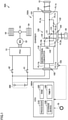
- Fig. 1 shows a configuration of a vehicle 50A according to a first embodiment.
- vehicle 50A includes an inlet 10, an electric outlet 20, a charger 100A, a battery 200, and an ECU 500A.
- Charger 100A includes a housing 101. Housing 101 includes a DC port 102 that electrically connects charger 100A to battery 200, a first AC port 103, a second AC port 104 that outputs AC power, and a communication port 105 to which a communication line is connectable.
- ECU 500A controls charger 100A.
- ECU 500A according to the first embodiment corresponds to an example of "controller" according to the present disclosure.
- first AC port 103 When vehicle 50A performs external charging, AC power for charging battery 200 is input to first AC port 103.
- second AC port 104 outputs AC power.
- first AC port 103 When vehicle 50A performs external power feeding, first AC port 103 outputs AC power.
- the AC power input to first AC port 103 at the time of external charging corresponds to an example of "first AC power” according to the present disclosure.
- the AC power output from second AC port 104 at the time of electric outlet power feeding corresponds to an example of "second AC power” according to the present disclosure.
- the AC power output from first AC port 103 at the time of external power feeding corresponds to an example of "third AC power" according to the present disclosure.
- DC port 102 is a connector that connects, to charger 100A, a power line extending to battery 200.
- First AC port 103 is a connector that connects, to charger 100A, a power line extending to inlet 10 to which a charging plug is connectable.
- Second AC port 104 is a connector that connects, to charger 100A, a power line extending to electric outlet 20 that outputs AC power.
- Charger 100A is removable by each connector, which facilitates replacement of charger 100A.
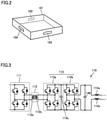
- Fig. 2 is a perspective view showing an example shape of housing 101.
- housing 101 has a shape of, for example, a flat box.
- Each of DC port 102, first AC port 103 and second AC port 104 is provided in, for example, a side surface of housing 101.
- the shape of housing 101 and the arrangement of each port are not limited to the example shown in Fig. 2 , and can be changed as appropriate.
- charger 100A includes, in housing 101, a bidirectional converter 110, a switching device 120, a limiting resistance 131, and a fuse 132.
- Bidirectional converter 110 converts the first AC power input to first AC port 103 at the time of external charging into DC power and outputs the DC power to DC port 102.
- bidirectional converter 110 converts DC power supplied from battery 200 to DC port 102 into the second AC power and outputs the second AC power to second AC port 104.
- bidirectional converter 110 converts the DC power supplied from battery 200 to DC port 102 into the third AC power and outputs the third AC power to first AC port 103.
- bidirectional converter 110 includes a capacitor 140 (see Fig. 3 ).
- Capacitor 140 is precharged by the first AC power at the start of external charging.
- Capacitor 140 is also precharged at the start of external power feeding.
- Limiting resistance 131 is an electric resistance that suppresses an inrush current at the time of precharging. Fuse 132 blows when an overcurrent flows.
- Fig. 3 shows an example circuit configuration of bidirectional converter 110.
- bidirectional converter 110 includes an inverter 111, an insulating circuit 112, an inverter 113, two reactors 114a and 114b, and capacitor 140.
- Inverter 111 is a full bridge circuit including four switching elements.
- Insulating circuit 112 is an insulating transformer including a first coil 112a and a second coil 112b. Insulating circuit 112 performs voltage transformation at a ratio corresponding to a winding ratio between first coil 112a and second coil 112b.
- Inverter 113 includes a first inverter 113a, a second inverter 113b and a smoothing capacitor 113c.
- Each of first inverter 113a and second inverter 113b is a full bridge circuit including four switching elements.
- Each switching element included in inverters 111 and 113 is controlled by ECU 500A.
- ECU 500A controls bidirectional converter 110 such that bidirectional converter 110 performs power conversion described below.
- various types of sensors e.g., a current sensor and a voltage sensor
- a current sensor and a voltage sensor may be provided at appropriate locations of the circuit shown in Fig. 3 in order to obtain information used by ECU 500A for control.
- inverter 111 converts DC power input from a first end (on the DC port 102 side shown in Fig. 1 ) into high-frequency AC power and outputs the high-frequency AC power to insulating circuit 112.
- Insulating circuit 112 transmits the output (AC power) of inverter 111 to first inverter 113a, and first inverter 113a rectifies the AC power received from insulating circuit 112 and outputs the rectified power to second inverter 113b.
- Second inverter 113b converts the DC power received from first inverter 113a into predetermined AC power and outputs the AC power to a second end (on the reactor 114a, 114b side).
- second inverter 113b rectifies AC power input from the second end and outputs the rectified power to first inverter 113a
- first inverter 113a converts the DC power received from second inverter 113b into high-frequency AC power.
- Insulating circuit 112 transmits the output (AC power) of first inverter 113a to inverter 111
- inverter 111 rectifies the AC power received from insulating circuit 112 and outputs the rectified power to the first end.
- switching device 120 includes CO (Change-Over) contact relays 121 and 122.
- CO contact relays 121 and 122 switch between connection and disconnection of power paths in a charging circuit.
- first power path a power path that connects bidirectional converter 110 and first AC port 103 not via limiting resistance 131
- first power path a power path that connects bidirectional converter 110 and first AC port 103 not via limiting resistance 131
- second power path a power path that connects bidirectional converter 110 and first AC port 103 not via limiting resistance 131
- a power line PL1a forms a part of the first power path having a first polarity
- a power line PL1b forms a part of the first power path having a second polarity.
- second power path A power path connecting bidirectional converter 110 and second AC port 104
- a power line PL2a forms a part of the second power path having the first polarity
- a power line PL2b forms a part of the second power path having the second polarity
- a power path connecting bidirectional converter 110 and first AC port 103 via limiting resistance 131 will be referred to as "third power path”.
- a power line PL1c forms a part of the third power path having the first polarity
- power line PL1b forms a part of the third power path having the second polarity.
- Switching device 120 selectively switches between the first power path and the second power path. Specifically, each of CO contact relays 121 and 122 brings one of the first power path and the second power path into a connected state and brings the other into a disconnected state. Each of CO contact relays 121 and 122 is implemented by an electromagnetic mechanical relay. CO contact relays 121 and 122 according to the first embodiment correspond to examples of "first CO contact relay” and "second CO contact relay", respectively.
- a power line PL11a having the first polarity and a power line PL11b having the second polarity are connected to the first end of bidirectional converter 110.
- a power line PL12a having the first polarity and a power line PL12b having the second polarity are connected to the second end of bidirectional converter 110.
- the electric power is input to the second end and output from the first end.
- the electric power is input to the first end and output from the second end.
- the first polarity and the second polarity are opposite to each other.
- Each of power lines PL11a and PL11b is connected to DC port 102.
- Power line PL12a branches off into power line PL1a and power line PL2a at a first branch point.
- CO contact relay 121 is arranged at the first branch point.
- Power line PL12b branches off into power line PL1b and power line PL2b at a second branch point.
- CO contact relay 122 is arranged at the second branch point.
- Power line PL11a and power line PL12a according to the first embodiment correspond to examples of "first power line” and "second power line” according to the present disclosure, respectively.
- Power line PL1c is connected to each of a position of CO contact relay 121 on the bidirectional converter 110 side and a position of CO contact relay 121 on the first AC port 103 side in power line PL1a.
- Limiting resistance 131 and fuse 132 connected in series are provided on power line PL1c.
- CO contact relay 121 is connected in parallel to limiting resistance 131.
- Limiting resistance 131 is connected in parallel to a position that bypasses CO contact relay 121 located on the first power path.
- CO contact relays 121 and 122 form a pair to switch between connection and disconnection of each of the power paths having the first polarity and the power paths having the second polarity.
- CO contact relay 121 is arranged at the first branch point to bring one of the first AC port 103 side (power line PL1a) and the second AC port 104 side (power line PL2a) into the connected state and bring the other into the disconnected state.
- CO contact relay 122 is arranged at the second branch point to bring one of the first AC port 103 side (power line PL1b) and the second AC port 104 side (power line PL2b) into the connected state and bring the other into the disconnected state.
- CO contact relay 121 When CO contact relay 121 is connected to power line PL1a (first power path), the second power path is disconnected. When CO contact relay 121 is connected to power line PL2a (second power path), the first power path is disconnected. When CO contact relay 122 is connected to power line PL1b (first power path), the second power path is disconnected. When CO contact relay 122 is connected to power line PL2b (second power path), each of the first power path and the third power path is disconnected.
- Inlet 10 is electrically connected to first AC port 103 of charger 100A through a power line.
- a connector is provided at a tip of the power line extending to inlet 10, and the connector of inlet 10 is connected to first AC port 103.
- Inlet 10 is placed such that a user can use inlet 10 from outside vehicle 50A.
- Inlet 10 may be provided in, for example, a rear side surface of a vehicle body.
- Inlet 10 is covered with a charging lid when not in use. When the user opens the charging lid, inlet 10 is exposed.
- EVSE electric vehicle supply equipment
- the plug of the EVSE is implemented by, for example, a connector of a charging cable, and when the plug is connected to inlet 10, the EVSE and vehicle 50A are electrically connected through the charging cable.
- the user can supply electric power from inlet 10 of vehicle 50A to the EVSE.
- the EVSE may reversely flow the electric power supplied from vehicle 50A to a not-shown power network.
- Electric outlet 20 is electrically connected to second AC port 104 of charger 100A through a power line.
- a connector is provided at a tip of the power line extending to electric outlet 20, and the connector of electric outlet 20 is connected to second AC port 104.
- Electric outlet 20 is implemented by a vehicle interior electric outlet placed in the interior of vehicle 50A. Electric outlet 20 outputs the second AC power.
- the second AC power is, for example, AC power having a voltage of 100 V.
- Battery 200 is electrically connected to DC port 102 of charger 100A through a power line. Battery 200 stores electric power for causing vehicle 50A to travel.
- Battery 200 is implemented by, for example, a secondary battery such as a lithium ion battery or a nickel metal hydride battery.
- a secondary battery such as a lithium ion battery or a nickel metal hydride battery.
- an assembled battery including a plurality of lithium ion batteries is used as the secondary battery.
- the assembled battery is formed by electrically connecting a plurality of cells to each other.
- Battery 200 according to the first embodiment corresponds to an example of "power storage device" according to the present disclosure.
- ECU 500A is connected to communication port 105 of charger 100A through a signal line.
- a component that operates in accordance with a control signal from ECU 500A is not provided between first AC port 103 and inlet 10 and between second AC port 104 and electric outlet 20. Therefore, the number of signal lines around charger 100A can be reduced.
- ECU 500A includes a processor 510, a random access memory (RAM) 520, a storage device 530, and a timer 540.
- a central processing unit (CPU) can, for example, be used as processor 510.
- RAM 520 functions as a working memory that temporarily stores data to be processed by processor 510.
- Storage device 530 can preserve the stored information.
- Storage device 530 includes, for example, a read only memory (ROM) and a rewritable non-volatile memory.
- information e.g., maps, mathematical formulas and various parameters
- processor 510 performs the programs stored in storage device 530, thereby performing various controls in ECU 500A.
- Timer 540 provides a notification about the arrival of the set time to processor 510.
- a signal indicating that the set time has come is transmitted from timer 540 to processor 510.
- ECU 500A can obtain the current time by using a real time clock (RTC) circuit (not shown) built into ECU 500A.
- RTC real time clock
- ECU 500A may accept a reservation of each of timer charging and timer power feeding from the user.
- the timer charging and the timer power feeding refer to external charging and external power feeding performed in accordance with preset schedules, respectively.
- the user may be able to input the schedule (start time and end time) of each of timer charging and timer power feeding into ECU 500A, and make a reservation of each of timer charging and timer power feeding in ECU 500A.
- the input device may be mounted on vehicle 50A, or may be implemented by a mobile terminal (e.g., smartphone).
- ECU 500A may perform each of the reserved timer charging and the reserved timer power feeding.
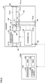
- Fig. 4 shows an example manner of transmission of control signals in housing 101 of charger 100A.
- ECU 500A is connected to each of bidirectional converter 110 and CO contact relays 121 and 122 in housing 101 through direct lines.
- Each direct line is a direct control line that directly connects devices on a one-to-one basis.
- ECU 500A can directly control each of bidirectional converter 110 and CO contact relays 121 and 122. By using the direct lines for transmission of the control signals, the control speed is increased.
- Fig. 5 shows a modification of the manner of transmission of the control signals shown in Fig. 4 .
- charger 100A includes a charging ECU 150 in housing 101.
- ECU 500A and charging ECU 150 can communicate with each other.
- ECU 500A and charging ECU 150 may be connected to each other through a controller area network (CAN) bus.
- a central gateway (CGW) may be provided between ECU 500A and charging ECU 150.
- Charging ECU 150 controls each of bidirectional converter 110 and CO contact relays 121 and 122 in accordance with the control signal from ECU 500A.
- ECU 500A may control bidirectional converter 110 through charging ECU 150 and ECU 500A may control CO contact relays 121 and 122 through the direct lines.
- vehicle 50A further includes a power control unit (PCU) 51, a motor generator (MG) 52, a motive power transmission gear 53, a driving wheel 54, system main relays (SMRs) 61 and 62, and a startup switch 70.
- PCU power control unit
- MG motor generator
- SMRs system main relays
- Vehicle 50A is an electrically-powered vehicle (e.g., electric vehicle) that travels using the electric power stored in battery 200.
- Each of SMRs 61 and 62 is provided on a power path that connects battery 200 and PCU 51.
- Each of SMRs 61 and 62 is implemented by, for example, an electromagnetic mechanical relay.
- a state (connected state/disconnected state) of each of SMRs 61 and 62 is controlled by ECU 500A.
- ECU 500A When each of SMRs 61 and 62 is in a connected state, electric power can be exchanged between battery 200 and PCU 51.
- each of SMRs 61 and 62 is in a disconnected state, electric power cannot be exchanged between battery 200 and PCU 51.
- Each of SMRs 61 and 62 is in the connected state during traveling of vehicle 50A.
- MG 52 is implemented by, for example, a three-phase AC motor generator. MG 52 is driven by PCU 51 to rotate driving wheel 54 of vehicle 50A. PCU 51 includes, for example, an inverter and a converter (both are not shown). The inverter and the converter of PCU 51 are controlled by ECU 500A. The output torque of MG 52 is transmitted to driving wheel 54 through motive power transmission gear 53 that serves as a decelerator. MG 52 also performs regenerative power generation and supplies generated electric power to battery 200.
- Startup switch 70 is a switch for starting up a vehicle system. Although the details will be described below, when startup switch 70 is operated in a stop state of the system, the vehicle system (including ECU 500A) starts up, and when startup switch 70 is operated during operation of the system, the vehicle system stops. Startup switch 70 is generally referred to as "power switch” or “ignition switch”.
- Charger 100A includes, in housing 101, bidirectional converter 110 (including capacitor 140), switching device 120 (CO contact relays 121 and 122), and limiting resistance 131.
- CO contact relay 121 is connected in parallel to limiting resistance 131.
- CO contact relay 121 functions as a precharge relay.
- DC port 102, first AC port 103 and second AC port 104 are provided in housing 101.
- Fig. 6 shows a manner of use of charger 300 according to Comparative Example 1.
- a configuration and a manner of use of charger 300 according to Comparative Example 1 will be described, with attention focused mainly on differences from the configuration and the manner of use of charger 100A shown in Fig. 1 .
- charger 300 includes a housing 301 having a DC port 302 and an AC port 303.
- Charger 300 includes, in housing 301, bidirectional converter 110 (including capacitor 140), limiting resistance 131, fuse 132, and a precharge relay 133.
- Precharge relay 133 is connected in parallel to limiting resistance 131.
- a power line PL3a having the first polarity and a power line PL3b having the second polarity are connected to AC port 303.
- Power line PL3a branches off into a power line PL31a and a power line PL32a at a third branch point.
- a CO contact relay 31 is arranged at the third branch point.
- Power line PL3b branches off into a power line PL31b and a power line PL32b at a fourth branch point.
- a CO contact relay 32 is arranged at the fourth branch point.
- Power line PL31a forms a part of the first power path having the first polarity
- power line PL31b forms a part of the first power path having the second polarity.
- Power line PL32a forms a part of the second power path having the first polarity
- power line PL32b forms a part of the second power path having the second polarity.
- a switching device (CO contact relays 31 and 32) that switches between connection and disconnection of each of the first power path and the second power path is provided outside housing 301.
- the number of relays around charger 300 is likely to increase and circuits around charger 300 is likely to become complicated.
- the burden of the wiring work is likely to increase and the frequency of occurrence of an abnormality is likely to increase.
- precharge relay 133 is provided inside housing 301.
- switching device 120 (CO contact relays 121 and 122) provided inside housing 101 can bring one of the first power path and the second power path into the connected state and bring the other into the disconnected state.
- the number of relays provided around charger 100A i.e., outside charger 100A
- CO contact relay 121 is connected in parallel to limiting resistance 131. Since CO contact relay 121 also functions as a precharge relay, the number of relays provided inside charger 100A can also be reduced.
- vehicle 50A including charger 100A
- charger 100A The operation of vehicle 50A (including charger 100A) according to the first embodiment will be described hereinafter with reference to Figs. 7 to 9 .
- Fig. 7 is a diagram for illustrating transition of a state of vehicle 50A.
- the state of vehicle 50A can be broadly categorized into “during traveling", “stop state”, “during external charging”, and “during external power feeding”.
- “relay A” refers to CO contact relay 121
- “relay B” refers to CO contact relay 122.
- During traveling refers to a state in which vehicle 50A can travel.
- the vehicle system starts up and SMRs 61 and 62 enter the connected state.
- SMRs 61 and 62 enter the connected state, vehicle 50A enters "during traveling”.
- the plug of the EVSE is connected to inlet 10
- the above-described traveling start operation is not enabled, and thus, the state transition from "stop state” to "during traveling” does not take place.
- “Stop state” described above refers to a state in which the vehicle system is at a standstill (including a sleep state).
- the vehicle system enters the stop state (e.g., sleep state) and vehicle 50A enters "stop state”.
- the stop state e.g., sleep state
- vehicle 50A enters "stop state”.
- the power paths are disconnected by bidirectional converter 110.
- During external charging refers to a state in which vehicle 50A is performing external charging. For example, when a predetermined charging start condition is satisfied, with the plug of the EVSE connected to inlet 10, while vehicle 50A is in “stop state", the vehicle system starts up and external charging is started. When external charging is started, vehicle 50A enters “during external charging”. Thereafter, when a predetermined charging end condition is satisfied, external charging ends, and the vehicle system enters the stop state and vehicle 50A enters "stop state”.
- the charging start condition may be satisfied when ECU 500A receives a charging start request from the EVSE. In a case where ECU 500A does not have a reservation of timer charging, the charging start condition may be satisfied when the plug of the EVSE is connected to inlet 10. In a case where ECU 500A has a reservation of timer charging, the charging start condition may be satisfied when the start time of timer charging comes, with the plug of the EVSE connected to inlet 10.
- the charging end condition may be satisfied when ECU 500A receives a charging end request from the EVSE.
- the charging end condition may be satisfied when an SOC (State Of Charge) of battery 200 becomes equal to or higher than a predetermined SOC value.
- SOC State Of Charge
- the charging start condition may not be satisfied.
- During external power feeding refers to a state in which vehicle 50A is performing external power feeding. For example, when a predetermined power feeding start condition is satisfied, with the plug of the EVSE connected to inlet 10, while vehicle 50A is in “stop state", the vehicle system starts up and external power feeding is started. When external power feeding is started, vehicle 50A enters “during power feeding”. Thereafter, when a predetermined power feeding end condition is satisfied, external power feeding ends, and the vehicle system enters the stop state and vehicle 50A enters "stop state”.
- the power feeding start condition may be satisfied when ECU 500A receives a power feeding start request from the EVSE.
- the power feeding start condition may be satisfied when the start time of timer power feeding comes, with the plug of the EVSE connected to inlet 10.
- the power feeding end condition may be satisfied when ECU 500A receives a power feeding end request from the EVSE. Alternatively, the power feeding end condition may be satisfied when the SOC of battery 200 becomes equal to or lower than the predetermined SOC value. When the SOC of battery 200 is equal to or lower than the predetermined SOC value before the start of external power feeding, the power feeding start condition may not be satisfied.
- ECU 500A connects both CO contact relays 121 and 122 to the electric outlet side.
- CO contact relay 121 is connected to power line PL2a (electric outlet side)
- the first power path having the first polarity enters the disconnected state.
- CO contact relay 122 is connected to power line PL2b (electric outlet side)
- the first power path having the second polarity enters the disconnected state.
- the second power path enters the connected state.
- ECU 500A controls bidirectional converter 110 such that the second AC power is output to electric outlet 20. Therefore, an occupant can use electric outlet 20 (vehicle interior electric outlet) during traveling of vehicle 50A.
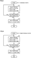
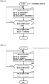
- ECU 500A When external charging (i.e., charging of battery 200 using the first AC power) is started, ECU 500A performs a process shown in Fig. 8 described below, thereby controlling CO contact relays 121 and 122 (switching relays).
- Fig. 8 is a flowchart showing relay control performed by ECU 500A at the start of external charging. The process shown in this flowchart is performed when external charging is started.
- ECU 500A connects CO contact relays 121 and 122 to the electric outlet side and the inlet side, respectively.
- CO contact relay 121 is connected to power line PL2a (electric outlet side)
- the first power path having the first polarity enters the disconnected state.
- CO contact relay 122 is connected to power line PL1b (inlet side)
- the second power path having the second polarity enters the disconnected state.
- the inrush current is suppressed by limiting resistance 131 and precharging of capacitor 140 is performed.
- ECU 500A determines whether or not the precharging has been completed. When a voltage of capacitor 140 reaches a predetermined reference value, ECU 500A may determine that the precharging has been completed.
- ECU 500A controls switching device 120 such that when external charging is started, CO contact relay 121 connected in parallel to limiting resistance 131 brings the first power path into the disconnected state and thus limiting resistance 131 suppresses the inrush current at the time of precharging (S11), and when the precharging is completed (YES in S12), CO contact relay 121 brings the first power path into the connected state (S13). With such control, an inrush current at the start of external charging (during precharging) can be suppressed.
- ECU 500A When external power feeding (i.e., power feeding for outputting the third AC power from first AC port 103 to inlet 10) is started, ECU 500A performs a process shown in Fig. 9 described below, thereby controlling CO contact relays 121 and 122 (switching relays).
- external power feeding i.e., power feeding for outputting the third AC power from first AC port 103 to inlet 10.
- Fig. 9 is a flowchart showing relay control performed by ECU 500A at the start of external power feeding. The process shown in this flowchart is performed when external power feeding is started.
- ECU 500A controls switching device 120 such that when external power feeding is started, CO contact relay 121 connected in parallel to limiting resistance 131 brings the first power path into the disconnected state and thus limiting resistance 131 suppresses the inrush current at the time of precharging (S21), and when the precharging is completed (YES in S22), CO contact relay 121 brings the first power path into the connected state (S23). With such control, the inrush current at the start of external power feeding (at the time of precharging) can be suppressed.
- vehicle 50B according to a second embodiment will be described, with attention focused mainly on differences from vehicle 50A (including charger 100A) according to the first embodiment.
- Fig. 10 shows a configuration of vehicle 50B according to the second embodiment.
- vehicle 50B includes an ECU 500B instead of ECU 500A (first embodiment).
- ECU 500B according to the second embodiment corresponds to an example of "controller” according to the present disclosure.
- vehicle 50B includes a charger 100B instead of charger 100A (first embodiment).
- Charger 100B includes, in housing 101, bidirectional converter 110 (including capacitor 140), a switching device 160, limiting resistance 131, and fuse 132.
- Power line PL11a having the first polarity and power line PL11b having the second polarity are connected to the first end of bidirectional converter 110.
- Power line PL12a having the first polarity and power line PL12b having the second polarity are connected to the second end of bidirectional converter 110.
- Power line PL12a branches off into power line PL1a and power line PL2a at a branch point D1.
- Power line PL12b branches off into power line PL1b and power line PL2b at a branch point D2.
- Switching device 160 includes NO (Normally-Open) contact relays 161 to 164.
- NO contact relays 161 to 164 is implemented by an electromagnetic mechanical relay.
- Switching device 160 is configured such that each of NO contact relays 161 to 164 switches between connection and disconnection of each of the first power path, the second power path and the third power path.
- Each of NO contact relays 161 to 164 according to the second embodiment corresponds to an example of "switching relay" according to the present disclosure.
- NO contact relays 161 and 162 form a pair to switch between connection and disconnection of the first power path.
- NO contact relays 161 and 162 are arranged on power lines PL1a and PL1b, respectively.
- NO contact relays 161 and 162 are both in a connected state, the first power path is in a connected state.
- NO contact relays 161 and 162 enters a disconnected state, the first power path enters a disconnected state.
- NO contact relays 161 and 162 according to the second embodiment correspond to examples of "first switching relay" and "third switching relay", respectively.
- NO contact relays 163 and 164 form a pair to switch between connection and disconnection of the second power path.
- NO contact relays 163 and 164 are arranged on power lines PL2a and PL2b, respectively.
- the second power path is in a connected state.
- NO contact relays 163 and 164 enters a disconnected state, the second power path enters a disconnected state.
- NO contact relays 163 and 164 according to the second embodiment correspond to examples of "second switching relay" and "fourth switching relay", respectively.
- NO contact relay 161 is arranged between first AC port 103 and branch point D1 to switch between connection and disconnection of the first power path.
- NO contact relay 162 is arranged between first AC port 103 and branch point D2 to switch between connection and disconnection of the first power path.
- NO contact relay 163 is arranged between second AC port 104 and branch point D1 to switch between connection and disconnection of the second power path.
- NO contact relay 164 is arranged between second AC port 104 and branch point D2 to switch between connection and disconnection of the second power path.
- NO contact relay 161 is connected in parallel to limiting resistance 131. NO contact relay 161 functions as a precharge relay.
- FIG. 11 shows a manner of use of charger 300 according to Comparative Example 2.
- Charger 300 shown in Fig. 11 is the same as charger 300 shown in Fig. 6 .
- a manner of use of charger 300 according to Comparative Example 2 will be described, with attention focused mainly on differences from a manner of use of charger 100B shown in Fig. 10 .
- a power line PL4a having the first polarity and a power line PL4b having the second polarity are connected to AC port 303 of charger 300.
- Power line PL4a branches off into a power line PL41a and a power line PL42a at a branch point D3.
- NO contact relays 41 and 43 are provided on power lines PL41a and PL42a, respectively.
- Power line PL4b branches off into a power line PL41b and a power line PL42b at a branch point D4.
- NO contact relays 42 and 44 are provided on power lines PL41b and PL42b, respectively.
- the switching device (NO contact relays 41 to 44) that switches between connection and disconnection of each of the first power path and the second power path is provided outside housing 301.
- the number of relays around charger 300 is likely to increase and circuits around charger 300 is likely to become complicated.
- the burden of the wiring work is likely to increase and the frequency of occurrence of an abnormality is likely to increase.
- precharge relay 133 is provided inside housing 301.
- switching device 160 (NO contact relays 161 to 164) provided inside housing 101 can bring one of the first power path and the second power path into the connected state and bring the other into the disconnected state.
- the number of relays provided around charger 100B i.e., outside charger 100B
- NO contact relay 161 is connected in parallel to limiting resistance 131. Since NO contact relay 161 also functions as a precharge relay, the number of relays provided inside charger 100B can also be reduced.
- Fig. 12 shows a manner of control of the switching relays (NO contact relays 161 to 164) for each state of vehicle 50B.
- “relay A” refers to NO contact relay 161
- “relay B” refers to NO contact relay 162
- “relay C” refers to NO contact relay 163
- “relay D” refers to NO contact relay 164.
- ECU 500B brings NO contact relays 161 and 162 into the disconnected state and brings NO contact relays 163 and 164 into the connected state. As a result, the first power path enters the disconnected state, and the second power path enters the connected state. As described above, since the second power path is in the connected state during traveling of vehicle 50B, electric power can be supplied from battery 200 to electric outlet 20. When vehicle 50B is in "during traveling", ECU 500B controls bidirectional converter 110 such that the second AC power is output to electric outlet 20. Therefore, an occupant can use electric outlet 20 (vehicle interior electric outlet) during traveling of vehicle 50B.
- ECU 500B When external charging is started, ECU 500B according to the second embodiment performs a process shown in Fig. 13 described below, instead of the process shown in Fig. 8 , thereby controlling NO contact relays 161 to 164 (switching relays).
- Fig. 13 is a flowchart showing relay control performed by ECU 500B at the start of external charging. The process shown in this flowchart is performed when external charging is started.
- ECU 500B brings NO contact relay 162 into the connected state and bring NO contact relays 161, 163 and 164 into the disconnected state.
- NO contact relay 162 With such relay control, only the third power path, of the first to the third power path, enters the connected state.
- the inrush current is suppressed by limiting resistance 131 and precharging of capacitor 140 is performed.
- ECU 500B determines whether or not the precharging has been completed. When a voltage of capacitor 140 reaches a predetermined reference value, ECU 500B may determine that the precharging has been completed.
- ECU 500B controls switching device 160 such that when external charging is started, NO contact relay 161 connected in parallel to limiting resistance 131 brings the first power path into the disconnected state and thus limiting resistance 131 suppresses the inrush current at the time of precharging (S31), and when the precharging is completed (YES in S32), NO contact relay 161 brings the first power path into the connected state (S33). With such control, the inrush current at the start of external charging (at the time of precharging) can be suppressed.
- ECU 500B When external power feeding (i.e., power feeding for outputting the third AC power from first AC port 103 to inlet 10) is started, ECU 500B performs a process shown in Fig. 14 described below, thereby controlling NO contact relays 161 to 164 (switching relays).
- Fig. 14 is a flowchart showing relay control performed by ECU 500B at the start of external power feeding. The process shown in this flowchart is performed when external power feeding is started.
- ECU 500B controls switching device 160 such that when external power feeding is started, NO contact relay 161 connected in parallel to limiting resistance 131 brings the first power path into the disconnected state and thus limiting resistance 131 suppresses the inrush current at the time of precharging (S41), and when the precharging is completed (YES in S42), NO contact relay 161 brings the first power path into the connected state (S43). With such control, the inrush current at the start of external power feeding (at the time of precharging) can be suppressed.
- electric outlet power feeding is not performed when the vehicle is not in “during traveling”.
- the present disclosure is not limited thereto, and electric outlet power feeding may be performed when the vehicle is not in "during traveling".
- all of NO contact relays 161 and 164 may enter the connected state when vehicle 50B is in "during external charging”.
- Electric outlet 20 may include a built-in power conversion circuit that performs predetermined power conversion (e.g., voltage transformation) of the second AC power output from second AC port 104.
- the power conversion circuit built into electric outlet 20 may step down the second AC power, such that AC power having a voltage of 100 V is output from electric outlet 20.
- the configuration of the vehicle is not limited to the configurations shown in Figs. 1 and 10 . Although each of Figs. 1 and 10 shows the configuration in which only one MG is provided, the number of MGs is not limited thereto, and a plurality of (e.g., two) MGs may be provided.
- the vehicle is not limited to an electric vehicle (EV) and may be, for example, a plug-in hybrid vehicle (PHV).
- SMRs 61 and 62 may be provided at a position closer to battery 200 such that SMRs 61 and 62 are located between battery 200 and the charger.
- the ECU may bring SMRs 61 and 62 into the disconnected state when the vehicle is in "stop state", and bring SMRs 61 and 62 into the connected state when the vehicle is in any of "during traveling", “during external charging” and “during external power feeding”.
- relays may be added onto power lines PL11a and PL11b in housing 101.
- the ECU controller
- the ECU may bring the added relays into the disconnected state when the vehicle is in "stop state”, and bring the added relays into the connected state when the vehicle is in any of "during traveling", “during external charging” and “during external power feeding”.
- the number of switching relays provided in the housing of the charger can be changed as appropriate. For example, in the configuration shown in Fig. 10 , NO contact relay 162 may be omitted.
- the capacitor to be precharged may be provided at a position apart from the bidirectional converter.
- the capacitor to be precharged may be provided outside the housing of the charger.
- each of first AC port 103 and second AC port 104 is a connector.
- Fig. 15 shows a modification of first AC port 103 and second AC port 104 shown in Fig. 2 .
- a first AC port 103A and a second AC port 104A are provided in a side surface of a housing 101A.
- First AC port 103A corresponds to an inlet.
- a charging plug is connectable to the inlet.
- Second AC port 104A corresponds to an electric outlet.
- An electric outlet plug is connectable to the electric outlet.
- a plug can be connected to housing 101A.
- a charger including such housing 101A may be applied to a small-sized mobile body, or may be applied to a unit other than the mobile body.
- the shape of housing 101A and the arrangement of each port are not limited to the example shown in Fig. 15 , and can be changed as appropriate.
- the power storage device to which the charger is applied may be a power storage device mounted on a transportation means other than a vehicle (such as a ship or an airplane), or may be a power storage device mounted on an unmanned mobile body (such as an automated guided vehicle (AGV), an agricultural machine, a mobile robot, or a drone), or may be a power storage device mounted on a mobile device (such as a smartphone or a wearable device), or may be a power storage device placed in a building (such as a house or a factory).
- a transportation means other than a vehicle such as a ship or an airplane
- an unmanned mobile body such as an automated guided vehicle (AGV), an agricultural machine, a mobile robot, or a drone
Landscapes
- Engineering & Computer Science (AREA)
- Power Engineering (AREA)
- Transportation (AREA)
- Mechanical Engineering (AREA)
- Charge And Discharge Circuits For Batteries Or The Like (AREA)
- Electric Propulsion And Braking For Vehicles (AREA)
- Protection Of Static Devices (AREA)
- Direct Current Feeding And Distribution (AREA)
- Secondary Cells (AREA)
Abstract
Description
- This nonprovisional application is based on
Japanese Patent Application No. 2020-157378 filed on September 18, 2020 - The present disclosure relates to a charger and a vehicle.
- For example, a vehicle described in
Japanese Patent Laying-Open No. 2013-240191 - In the vehicle described in
Japanese Patent Laying-Open No. 2013-240191 - As described above, in a charger that can perform both charging and power feeding and performs precharging at the start of charging, the number of relays provided around the charger tends to increase. When the number of relays provided around the charger increases and circuits around the charger become complicated, the burden of the wiring work is likely to increase and the frequency of occurrence of an abnormality is likely to increase. When a precharge relay is provided inside the charger, it is concerned that the number of relays provided inside the charger increases. An increase in the number of components provided inside the charger and an increase in the number of components provided around the charger both lead to an increase in cost.
- The present disclosure has been made to solve the above-described problem, and an object of the present disclosure is to reduce the number of relays provided around a charger while simplifying a circuit inside the charger, and suitably perform charging and power feeding by the charger.
- A charger according to a first aspect of the present disclosure includes: a bidirectional converter; a DC port that electrically connects the charger to a power storage device; a first AC port that receives first AC power for charging the power storage device; and a second AC port that outputs second AC power. The bidirectional converter converts the first AC power into DC power and outputs the DC power to the DC port, and converts DC power supplied from the power storage device to the DC port into the second AC power and outputs the second AC power to the second AC port. The charger further includes: a switching device including at least one switching relay that selectively switches between a first power path and a second power path, the first power path connecting the bidirectional converter and the first AC port, the second power path connecting the bidirectional converter and the second AC port; and an electric resistance connected in parallel to a position that bypasses a switching relay on the first power path, of the at least one switching relay. Hereinafter, the electric resistance connected in parallel to the position that bypasses the switching relay on the first power path will also be referred to as "limiting resistance".
- In the above-described charger, the bidirectional converter converts the AC power (first AC power) input to the first AC port into the DC power. The power storage device can be charged with the thus-obtained DC power. The bidirectional converter also converts the DC power supplied from the power storage device to the DC port into the AC power (second AC power). The thus-obtained AC power is output from the second AC port, and thus, power feeding by the charger can be suitably performed.
- In the above-described charger, the switching device can bring one of the first power path and the second power path into a connected state and bring the other into a disconnected state. Thus, switching of the power path by the charger can be suitably performed. In addition, since the switching device is provided inside the charger, the number of relays provided around the charger (i.e., outside the charger) can be reduced. Furthermore, in the above-described charger, the electric resistance (limiting resistance) is connected in parallel to the position that bypasses the switching relay on the first power path, of the at least one switching relay of the switching device. Since the switching relay also functions as a precharge relay, the number of relays provided inside the charger can also be reduced.
- As described above, according to the above-described configuration, it is possible to reduce the number of relays provided around the charger while simplifying a circuit inside the charger, and suitably perform charging and power feeding by the charger.
- The limiting resistance may be arranged between the first AC port and the bidirectional converter. The limiting resistance may be connected in series to a fuse. The switching relay may be implemented by an electromagnetic mechanical relay. The switching relay may be implemented by an electromagnetic contactor that is generally referred to as "contactor".
- The bidirectional converter may be connected to each of a first power line and a second power line. The first power line may be connected to the DC port. The second power line may branch off into the first power path and the second power path at a branch point.
- In the above-described configuration, the power line branches off inside the charger, and thus, circuits around the charger (i.e., circuits outside the charger) are simplified.
- The switching relay on the first power path may be a CO (Change-Over) contact relay arranged at the branch point to bring one of the first power path and the second power path into a connected state and bring the other into a disconnected state.
- In the above-described configuration, the CO contact relay can bring one of the first power path and the second power path into the connected state and bring the other into the disconnected state. According to the above-described configuration, the number of relays can be reduced, as compared with a configuration in which relays are separately provided on the first power path and the second power path.
- The CO contact relay may be a first CO contact relay provided on a power path having a first polarity, and a second CO contact relay paired with the first CO contact relay may be provided on a power path having a second polarity opposite to the first polarity.
- The switching relay on the first power path may be a first switching relay arranged between the first AC port and the branch point to switch between connection and disconnection of the first power path. The at least one switching relay in the switching device may further include a second switching relay arranged between the second AC port and the branch point to switch between connection and disconnection of the second power path.
- In the above-described configuration, the first switching relay and the second switching relay are provided on the first power path and the second power path, respectively. According to the above-described configuration, both of the first power path and the second power path can be brought into the connected state or the disconnected state as needed.
- The first switching relay may be provided on the first power path having the first polarity, and a third switching relay paired with the first switching relay may be provided on the first power path having the second polarity opposite to the first polarity. The second switching relay may be provided on the second power path having the first polarity, and a fourth switching relay paired with the second switching relay may be provided on the second power path having the second polarity opposite to the first polarity.
- The DC port may be a connector that connects, to the charger, a power line extending to the power storage device. The first AC port may be a connector that connects, to the charger, a power line extending to an inlet to which a charging plug is connectable. The second AC port may be a connector that connects, to the charger, a power line extending to an electric outlet that outputs AC power.
- The above-described charger can perform charging of the power storage device using the electric power input to the inlet, and power feeding to the electric outlet using the electric power supplied from the power storage device to the DC port. In addition, the charger is removable by each connector, which facilitates replacement of the charger.
- The above-described charger may be connectable through the first AC port to a plurality of types of inlets having different specifications. The above-described electric outlet may output the second AC power output from the second AC port as it is, or may include a built-in power conversion circuit that performs predetermined power conversion (e.g., voltage transformation) of the second AC power.
- The charger may include a capacitor precharged by the first AC power at the start of charging of the power storage device. The capacitor may be included in the bidirectional converter.
- A vehicle according to a second aspect of the present disclosure includes: any charger described above; and a controller that controls the charger. The controller controls the switching device such that when charging of the power storage device using the first AC power is started, the switching relay on the first power path brings the first power path into a disconnected state and thus the limiting resistance suppresses an inrush current at the time of precharging, and when the precharging is completed, the switching relay on the first power path brings the first power path into a connected state.
- In the above-described vehicle, the controller controls the charger, and thus, charging and power feeding by the charger can be performed. In addition, the above-described control makes it possible to suppress the inrush current at the start of charging (at the time of precharging).
- The vehicle may further include: the power storage device electrically connected to the DC port of the charger; an inlet electrically connected to the first AC port of the charger; and a vehicle interior electric outlet electrically connected to the second AC port of the charger.
- The above-described vehicle can perform external charging of the power storage device using the electric power input to the inlet. The external charging refers to charging of the power storage device using the electric power supplied from outside the vehicle. The above-described vehicle can also perform power feeding to the vehicle interior electric outlet using the electric power of the power storage device. Hereinafter, the power feeding to the vehicle interior electric outlet will also be referred to as "electric outlet power feeding". As a result of the electric outlet power feeding, the vehicle interior electric outlet becomes available, which improves the convenience of an occupant. The electric power output to the vehicle interior electric outlet may be AC power having a voltage of 100 V or higher, or may be AC power having a voltage lower than 100 V.
- The vehicle may be configured such that a component that operates in accordance with a control signal from the controller is not provided between the first AC port and the inlet and between the second AC port and the vehicle interior electric outlet.
- According to the above-described configuration, the number of signal lines around the charger can be reduced.
- At least during traveling of the vehicle, the controller may bring the first power path into the disconnected state and bring the second power path into the connected state.
- According to the above-described configuration, an occupant can use the vehicle interior electric outlet during traveling of the vehicle.
- The first AC port may output third AC power. The bidirectional converter may convert the DC power supplied from the power storage device to the DC port into the third AC power and output the third AC power to the first AC port. The controller may control the switching device such that when external power feeding for outputting the third AC power from the first AC port to the inlet is started, the switching relay connected in parallel to the limiting resistance brings the first power path into the disconnected state and thus the limiting resistance suppresses an inrush current, and then, the switching relay connected in parallel to the limiting resistance brings the first power path into the connected state.
- In the above-described vehicle, the charger can convert the electric power of the power storage device into the third AC power and output the third AC power from the first AC port to the inlet. That is, the above-described vehicle can perform external power feeding. The external power feeding refers to supply of the electric power from the inlet of the vehicle to outside the vehicle. In addition, the above-described control makes it possible to suppress the inrush current at the start of external power feeding.
- The above-described vehicle may be an electrically-powered vehicle. The electrically-powered vehicle refers to a vehicle that travels using electric power stored in a power storage device. Examples of the electrically-powered vehicle include an electric vehicle (EV) and a plug-in hybrid vehicle (PHV).
- The foregoing and other objects, features, aspects and advantages of the present disclosure will become more apparent from the following detailed description of the present disclosure when taken in conjunction with the accompanying drawings.
-
-
Fig. 1 shows a configuration of a vehicle according to a first embodiment of the present disclosure. -
Fig. 2 is a perspective view showing an example shape of a housing of a charger shown inFig. 1 . -
Fig. 3 shows an example circuit configuration of a bidirectional converter shown inFig. 1 . -
Fig. 4 shows an example manner of transmission of control signals in the housing of the charger shown inFig. 1 . -
Fig. 5 shows a modification of the manner of transmission of the control signals shown inFig. 4 . -
Fig. 6 shows a manner of use of a charger according to Comparative Example 1. -
Fig. 7 is a diagram for illustrating transition of a state of the vehicle according to the first embodiment of the present disclosure. -
Fig. 8 is a flowchart showing relay control performed by a controller at the start of external charging in the first embodiment of the present disclosure. -
Fig. 9 is a flowchart showing relay control performed by the controller at the start of external power feeding in the first embodiment of the present disclosure. -
Fig. 10 shows a configuration of a vehicle according to a second embodiment of the present disclosure. -
Fig. 11 shows a manner of use of a charger according to Comparative Example 2. -
Fig. 12 shows a manner of control of switching relays for each state of the vehicle according to the second embodiment of the present disclosure. -
Fig. 13 is a flowchart showing relay control performed by a controller at the start of external charging in the second embodiment of the present disclosure. -
Fig. 14 is a flowchart showing relay control performed by the controller at the start of external power feeding in the second embodiment of the present disclosure. -
Fig. 15 shows a modification of a first AC port and a second AC port shown inFig. 2 . - Embodiments of the present disclosure will be described in detail with reference to the drawings, in which the same or corresponding portions are denoted by the same reference characters and description thereof will not be repeated. Hereinafter, an electronic control unit will also be referred to as "ECU".
-
Fig. 1 shows a configuration of avehicle 50A according to a first embodiment. Referring toFig. 1 ,vehicle 50A includes aninlet 10, anelectric outlet 20, acharger 100A, abattery 200, and anECU 500A.Charger 100A includes ahousing 101.Housing 101 includes aDC port 102 that electrically connectscharger 100A tobattery 200, afirst AC port 103, asecond AC port 104 that outputs AC power, and acommunication port 105 to which a communication line is connectable.ECU 500A controlscharger 100A.ECU 500A according to the first embodiment corresponds to an example of "controller" according to the present disclosure. - When
vehicle 50A performs external charging, AC power for chargingbattery 200 is input tofirst AC port 103. Whenvehicle 50A performs electric outlet power feeding,second AC port 104 outputs AC power. Whenvehicle 50A performs external power feeding,first AC port 103 outputs AC power. The AC power input tofirst AC port 103 at the time of external charging corresponds to an example of "first AC power" according to the present disclosure. The AC power output fromsecond AC port 104 at the time of electric outlet power feeding corresponds to an example of "second AC power" according to the present disclosure. The AC power output fromfirst AC port 103 at the time of external power feeding corresponds to an example of "third AC power" according to the present disclosure. -
DC port 102 is a connector that connects, to charger 100A, a power line extending tobattery 200.First AC port 103 is a connector that connects, to charger 100A, a power line extending toinlet 10 to which a charging plug is connectable.Second AC port 104 is a connector that connects, to charger 100A, a power line extending toelectric outlet 20 that outputs AC power.Charger 100A is removable by each connector, which facilitates replacement ofcharger 100A. -
Fig. 2 is a perspective view showing an example shape ofhousing 101. Referring toFig. 2 ,housing 101 has a shape of, for example, a flat box. Each ofDC port 102,first AC port 103 andsecond AC port 104 is provided in, for example, a side surface ofhousing 101. The shape ofhousing 101 and the arrangement of each port are not limited to the example shown inFig. 2 , and can be changed as appropriate. - Referring again to
Fig. 1 ,charger 100A includes, inhousing 101, abidirectional converter 110, aswitching device 120, a limitingresistance 131, and afuse 132.Bidirectional converter 110 converts the first AC power input tofirst AC port 103 at the time of external charging into DC power and outputs the DC power toDC port 102. At the time of electric outlet power feeding,bidirectional converter 110 converts DC power supplied frombattery 200 toDC port 102 into the second AC power and outputs the second AC power tosecond AC port 104. At the time of external power feeding,bidirectional converter 110 converts the DC power supplied frombattery 200 toDC port 102 into the third AC power and outputs the third AC power tofirst AC port 103. Although the details will be described below,bidirectional converter 110 includes a capacitor 140 (seeFig. 3 ).Capacitor 140 is precharged by the first AC power at the start of external charging.Capacitor 140 is also precharged at the start of external power feeding. Limitingresistance 131 is an electric resistance that suppresses an inrush current at the time of precharging. Fuse 132 blows when an overcurrent flows. -
Fig. 3 shows an example circuit configuration ofbidirectional converter 110. Referring toFig. 3 ,bidirectional converter 110 includes aninverter 111, an insulatingcircuit 112, aninverter 113, tworeactors capacitor 140.Inverter 111 is a full bridge circuit including four switching elements. Insulatingcircuit 112 is an insulating transformer including afirst coil 112a and asecond coil 112b.
Insulatingcircuit 112 performs voltage transformation at a ratio corresponding to a winding ratio betweenfirst coil 112a andsecond coil 112b.Inverter 113 includes afirst inverter 113a, asecond inverter 113b and a smoothingcapacitor 113c. Each offirst inverter 113a andsecond inverter 113b is a full bridge circuit including four switching elements. Each switching element included ininverters ECU 500A. - At the time of each of power feeding and charging,
ECU 500A controlsbidirectional converter 110 such thatbidirectional converter 110 performs power conversion described below. Although not shown inFig. 3 , various types of sensors (e.g., a current sensor and a voltage sensor) may be provided at appropriate locations of the circuit shown inFig. 3 in order to obtain information used byECU 500A for control. - At the time of power feeding,
inverter 111 converts DC power input from a first end (on theDC port 102 side shown inFig. 1 ) into high-frequency AC power and outputs the high-frequency AC power to insulatingcircuit 112. Insulatingcircuit 112 transmits the output (AC power) ofinverter 111 tofirst inverter 113a, andfirst inverter 113a rectifies the AC power received from insulatingcircuit 112 and outputs the rectified power tosecond inverter 113b.Second inverter 113b converts the DC power received fromfirst inverter 113a into predetermined AC power and outputs the AC power to a second end (on thereactor - At the time of charging,
second inverter 113b rectifies AC power input from the second end and outputs the rectified power tofirst inverter 113a, andfirst inverter 113a converts the DC power received fromsecond inverter 113b into high-frequency AC power. Insulatingcircuit 112 transmits the output (AC power) offirst inverter 113a toinverter 111, andinverter 111 rectifies the AC power received from insulatingcircuit 112 and outputs the rectified power to the first end. - Referring again to
Fig. 1 , switchingdevice 120 includes CO (Change-Over) contact relays 121 and 122. CO contact relays 121 and 122 switch between connection and disconnection of power paths in a charging circuit. Hereinafter, a power path that connectsbidirectional converter 110 andfirst AC port 103 not via limitingresistance 131 will be referred to as "first power path". A power line PL1a forms a part of the first power path having a first polarity, and a power line PL1b forms a part of the first power path having a second polarity. A power path connectingbidirectional converter 110 andsecond AC port 104 will be referred to as "second power path". A power line PL2a forms a part of the second power path having the first polarity, and a power line PL2b forms a part of the second power path having the second polarity. A power path connectingbidirectional converter 110 andfirst AC port 103 via limitingresistance 131 will be referred to as "third power path". A power line PL1c forms a part of the third power path having the first polarity, and power line PL1b forms a part of the third power path having the second polarity. Although the details will be described below, switchingdevice 120 is configured such that each of CO contact relays 121 and 122 switches between connection and disconnection of each of the first power path, the second power path and the third power path. -
Switching device 120 selectively switches between the first power path and the second power path. Specifically, each of CO contact relays 121 and 122 brings one of the first power path and the second power path into a connected state and brings the other into a disconnected state. Each of CO contact relays 121 and 122 is implemented by an electromagnetic mechanical relay. CO contact relays 121 and 122 according to the first embodiment correspond to examples of "first CO contact relay" and "second CO contact relay", respectively. - A power line PL11a having the first polarity and a power line PL11b having the second polarity are connected to the first end of
bidirectional converter 110. A power line PL12a having the first polarity and a power line PL12b having the second polarity are connected to the second end ofbidirectional converter 110. At the time of charging, the electric power is input to the second end and output from the first end. At the time of power feeding, the electric power is input to the first end and output from the second end. The first polarity and the second polarity are opposite to each other. - Each of power lines PL11a and PL11b is connected to
DC port 102. Power line PL12a branches off into power line PL1a and power line PL2a at a first branch point.CO contact relay 121 is arranged at the first branch point. Power line PL12b branches off into power line PL1b and power line PL2b at a second branch point.CO contact relay 122 is arranged at the second branch point. Power line PL11a and power line PL12a according to the first embodiment correspond to examples of "first power line" and "second power line" according to the present disclosure, respectively. - Power line PL1c is connected to each of a position of
CO contact relay 121 on thebidirectional converter 110 side and a position ofCO contact relay 121 on thefirst AC port 103 side in power line PL1a. Limitingresistance 131 and fuse 132 connected in series are provided on power line PL1c.CO contact relay 121 is connected in parallel to limitingresistance 131. Limitingresistance 131 is connected in parallel to a position that bypassesCO contact relay 121 located on the first power path. - CO contact relays 121 and 122 form a pair to switch between connection and disconnection of each of the power paths having the first polarity and the power paths having the second polarity.
CO contact relay 121 is arranged at the first branch point to bring one of thefirst AC port 103 side (power line PL1a) and thesecond AC port 104 side (power line PL2a) into the connected state and bring the other into the disconnected state.CO contact relay 122 is arranged at the second branch point to bring one of thefirst AC port 103 side (power line PL1b) and thesecond AC port 104 side (power line PL2b) into the connected state and bring the other into the disconnected state. - When
CO contact relay 121 is connected to power line PL1a (first power path), the second power path is disconnected. WhenCO contact relay 121 is connected to power line PL2a (second power path), the first power path is disconnected. WhenCO contact relay 122 is connected to power line PL1b (first power path), the second power path is disconnected. WhenCO contact relay 122 is connected to power line PL2b (second power path), each of the first power path and the third power path is disconnected. -
Inlet 10 is electrically connected tofirst AC port 103 ofcharger 100A through a power line. A connector is provided at a tip of the power line extending toinlet 10, and the connector ofinlet 10 is connected tofirst AC port 103.Inlet 10 is placed such that a user can useinlet 10 fromoutside vehicle 50A.Inlet 10 may be provided in, for example, a rear side surface of a vehicle body.Inlet 10 is covered with a charging lid when not in use. When the user opens the charging lid,inlet 10 is exposed. When the user connects a plug of electric vehicle supply equipment (EVSE) toinlet 10, electric power can be supplied tovehicle 50A by using the EVSE. The plug of the EVSE is implemented by, for example, a connector of a charging cable, and when the plug is connected toinlet 10, the EVSE andvehicle 50A are electrically connected through the charging cable. During external power feeding, the user can supply electric power frominlet 10 ofvehicle 50A to the EVSE. The EVSE may reversely flow the electric power supplied fromvehicle 50A to a not-shown power network. -
Electric outlet 20 is electrically connected tosecond AC port 104 ofcharger 100A through a power line. A connector is provided at a tip of the power line extending toelectric outlet 20, and the connector ofelectric outlet 20 is connected tosecond AC port 104.Electric outlet 20 is implemented by a vehicle interior electric outlet placed in the interior ofvehicle 50A.Electric outlet 20 outputs the second AC power. The second AC power is, for example, AC power having a voltage of 100 V. -
Battery 200 is electrically connected toDC port 102 ofcharger 100A through a power line.Battery 200 stores electric power for causingvehicle 50A to travel.Battery 200 is implemented by, for example, a secondary battery such as a lithium ion battery or a nickel metal hydride battery. In the first embodiment, an assembled battery including a plurality of lithium ion batteries is used as the secondary battery. The assembled battery is formed by electrically connecting a plurality of cells to each other.Battery 200 according to the first embodiment corresponds to an example of "power storage device" according to the present disclosure. -
ECU 500A is connected tocommunication port 105 ofcharger 100A through a signal line. Invehicle 50A, a component that operates in accordance with a control signal fromECU 500A is not provided betweenfirst AC port 103 andinlet 10 and betweensecond AC port 104 andelectric outlet 20. Therefore, the number of signal lines aroundcharger 100A can be reduced. -
ECU 500A includes aprocessor 510, a random access memory (RAM) 520, astorage device 530, and atimer 540. A central processing unit (CPU) can, for example, be used asprocessor 510.RAM 520 functions as a working memory that temporarily stores data to be processed byprocessor 510.Storage device 530 can preserve the stored information.Storage device 530 includes, for example, a read only memory (ROM) and a rewritable non-volatile memory. In addition to programs, information (e.g., maps, mathematical formulas and various parameters) used by the programs is stored instorage device 530. In the first embodiment,processor 510 performs the programs stored instorage device 530, thereby performing various controls inECU 500A. -
Timer 540 provides a notification about the arrival of the set time toprocessor 510. When the time set attimer 540 comes, a signal indicating that the set time has come is transmitted fromtimer 540 toprocessor 510. In addition,ECU 500A can obtain the current time by using a real time clock (RTC) circuit (not shown) built intoECU 500A. -
ECU 500A may accept a reservation of each of timer charging and timer power feeding from the user. The timer charging and the timer power feeding refer to external charging and external power feeding performed in accordance with preset schedules, respectively. For example, by operating a predetermined input device (not shown), the user may be able to input the schedule (start time and end time) of each of timer charging and timer power feeding intoECU 500A, and make a reservation of each of timer charging and timer power feeding inECU 500A. The input device may be mounted onvehicle 50A, or may be implemented by a mobile terminal (e.g., smartphone).ECU 500A may perform each of the reserved timer charging and the reserved timer power feeding. -
Fig. 4 shows an example manner of transmission of control signals inhousing 101 ofcharger 100A. Referring toFig. 4 ,ECU 500A is connected to each ofbidirectional converter 110 and CO contact relays 121 and 122 inhousing 101 through direct lines. Each direct line is a direct control line that directly connects devices on a one-to-one basis.ECU 500A can directly control each ofbidirectional converter 110 and CO contact relays 121 and 122. By using the direct lines for transmission of the control signals, the control speed is increased. -
Fig. 5 shows a modification of the manner of transmission of the control signals shown inFig. 4 . Referring toFig. 5 , in the present modification,charger 100A includes a chargingECU 150 inhousing 101. WhenECU 500A is connected tocommunication port 105 through a signal line,ECU 500A and chargingECU 150 can communicate with each other.ECU 500A and chargingECU 150 may be connected to each other through a controller area network (CAN) bus. A central gateway (CGW) may be provided betweenECU 500A and chargingECU 150. ChargingECU 150 controls each ofbidirectional converter 110 and CO contact relays 121 and 122 in accordance with the control signal fromECU 500A. However, the present disclosure is not limited thereto, andECU 500A may controlbidirectional converter 110 through chargingECU 150 andECU 500A may control CO contact relays 121 and 122 through the direct lines. - Referring again to
Fig. 1 ,vehicle 50A further includes a power control unit (PCU) 51, a motor generator (MG) 52, a motivepower transmission gear 53, adriving wheel 54, system main relays (SMRs) 61 and 62, and astartup switch 70.Vehicle 50A is an electrically-powered vehicle (e.g., electric vehicle) that travels using the electric power stored inbattery 200. - Each of
SMRs battery 200 andPCU 51. Each ofSMRs SMRs ECU 500A. When each ofSMRs battery 200 andPCU 51. When each ofSMRs battery 200 andPCU 51. Each ofSMRs vehicle 50A. -
MG 52 is implemented by, for example, a three-phase AC motor generator.MG 52 is driven byPCU 51 to rotatedriving wheel 54 ofvehicle 50A.PCU 51 includes, for example, an inverter and a converter (both are not shown). The inverter and the converter ofPCU 51 are controlled byECU 500A. The output torque ofMG 52 is transmitted to drivingwheel 54 through motivepower transmission gear 53 that serves as a decelerator.MG 52 also performs regenerative power generation and supplies generated electric power tobattery 200. -
Startup switch 70 is a switch for starting up a vehicle system. Although the details will be described below, whenstartup switch 70 is operated in a stop state of the system, the vehicle system (includingECU 500A) starts up, and whenstartup switch 70 is operated during operation of the system, the vehicle system stops.Startup switch 70 is generally referred to as "power switch" or "ignition switch". -
Charger 100A according to the first embodiment includes, inhousing 101, bidirectional converter 110 (including capacitor 140), switching device 120 (CO contact relays 121 and 122), and limitingresistance 131.CO contact relay 121 is connected in parallel to limitingresistance 131.CO contact relay 121 functions as a precharge relay.DC port 102,first AC port 103 andsecond AC port 104 are provided inhousing 101. Hereinafter, an effect produced bysuch charger 100A will be described, in comparison with acharger 300 according to a comparative example. -
Fig. 6 shows a manner of use ofcharger 300 according to Comparative Example 1. Hereinafter, a configuration and a manner of use ofcharger 300 according to Comparative Example 1 will be described, with attention focused mainly on differences from the configuration and the manner of use ofcharger 100A shown inFig. 1 . - Referring to
Fig. 6 ,charger 300 includes ahousing 301 having aDC port 302 and anAC port 303.Charger 300 includes, inhousing 301, bidirectional converter 110 (including capacitor 140), limitingresistance 131,fuse 132, and aprecharge relay 133.Precharge relay 133 is connected in parallel to limitingresistance 131. - A power line PL3a having the first polarity and a power line PL3b having the second polarity are connected to
AC port 303. Power line PL3a branches off into a power line PL31a and a power line PL32a at a third branch point. ACO contact relay 31 is arranged at the third branch point. Power line PL3b branches off into a power line PL31b and a power line PL32b at a fourth branch point. ACO contact relay 32 is arranged at the fourth branch point. Power line PL31a forms a part of the first power path having the first polarity, and power line PL31b forms a part of the first power path having the second polarity. Power line PL32a forms a part of the second power path having the first polarity, and power line PL32b forms a part of the second power path having the second polarity. - In Comparative Example 1, a switching device (CO contact relays 31 and 32) that switches between connection and disconnection of each of the first power path and the second power path is provided outside
housing 301. Incharger 300, the number of relays aroundcharger 300 is likely to increase and circuits aroundcharger 300 is likely to become complicated. When the circuits aroundcharger 300 become complicated, the burden of the wiring work is likely to increase and the frequency of occurrence of an abnormality is likely to increase. In addition to the switching device (CO contact relays 31 and 32) providedoutside housing 301,precharge relay 133 is provided insidehousing 301. - In contrast, in
charger 100A according to the first embodiment, as shown inFig. 1 , switching device 120 (CO contact relays 121 and 122) provided insidehousing 101 can bring one of the first power path and the second power path into the connected state and bring the other into the disconnected state. Thus, the number of relays provided aroundcharger 100A (i.e., outsidecharger 100A) can be reduced. Furthermore, incharger 100A,CO contact relay 121 is connected in parallel to limitingresistance 131. SinceCO contact relay 121 also functions as a precharge relay, the number of relays provided insidecharger 100A can also be reduced. - The operation of
vehicle 50A (includingcharger 100A) according to the first embodiment will be described hereinafter with reference toFigs. 7 to 9 . -
Fig. 7 is a diagram for illustrating transition of a state ofvehicle 50A. Referring toFig. 7 together withFig. 1 , the state ofvehicle 50A can be broadly categorized into "during traveling", "stop state", "during external charging", and "during external power feeding". InFig. 7 andFigs. 8 and 9 described below, "relay A" refers toCO contact relay 121, and "relay B" refers toCO contact relay 122. - "During traveling" described above refers to a state in which
vehicle 50A can travel. For example, when the user performs a predetermined traveling start operation onstartup switch 70 whilevehicle 50A is in "stop state", the vehicle system starts up andSMRs vehicle 50A enters "during traveling". However, when the plug of the EVSE is connected toinlet 10, the above-described traveling start operation is not enabled, and thus, the state transition from "stop state" to "during traveling" does not take place. - "Stop state" described above refers to a state in which the vehicle system is at a standstill (including a sleep state). When the user performs a predetermined traveling stop operation on
startup switch 70, withvehicle 50A parked, whilevehicle 50A is in "during traveling", the vehicle system enters the stop state (e.g., sleep state) andvehicle 50A enters "stop state". Whenvehicle 50A is in "stop state", the power paths are disconnected bybidirectional converter 110. - "During external charging" described above refers to a state in which
vehicle 50A is performing external charging. For example, when a predetermined charging start condition is satisfied, with the plug of the EVSE connected toinlet 10, whilevehicle 50A is in "stop state", the vehicle system starts up and external charging is started. When external charging is started,vehicle 50A enters "during external charging". Thereafter, when a predetermined charging end condition is satisfied, external charging ends, and the vehicle system enters the stop state andvehicle 50A enters "stop state". - The charging start condition may be satisfied when
ECU 500A receives a charging start request from the EVSE. In a case whereECU 500A does not have a reservation of timer charging, the charging start condition may be satisfied when the plug of the EVSE is connected toinlet 10. In a case whereECU 500A has a reservation of timer charging, the charging start condition may be satisfied when the start time of timer charging comes, with the plug of the EVSE connected toinlet 10. - The charging end condition may be satisfied when
ECU 500A receives a charging end request from the EVSE. Alternatively, the charging end condition may be satisfied when an SOC (State Of Charge) ofbattery 200 becomes equal to or higher than a predetermined SOC value. When the SOC ofbattery 200 is equal to or higher than the predetermined SOC value before the start of external charging, the charging start condition may not be satisfied. - "During external power feeding" described above refers to a state in which
vehicle 50A is performing external power feeding. For example, when a predetermined power feeding start condition is satisfied, with the plug of the EVSE connected toinlet 10, whilevehicle 50A is in "stop state", the vehicle system starts up and external power feeding is started. When external power feeding is started,vehicle 50A enters "during power feeding". Thereafter, when a predetermined power feeding end condition is satisfied, external power feeding ends, and the vehicle system enters the stop state andvehicle 50A enters "stop state". - The power feeding start condition may be satisfied when
ECU 500A receives a power feeding start request from the EVSE. WhenECU 500A has a reservation of timer power feeding, the power feeding start condition may be satisfied when the start time of timer power feeding comes, with the plug of the EVSE connected toinlet 10. - The power feeding end condition may be satisfied when
ECU 500A receives a power feeding end request from the EVSE. Alternatively, the power feeding end condition may be satisfied when the SOC ofbattery 200 becomes equal to or lower than the predetermined SOC value. When the SOC ofbattery 200 is equal to or lower than the predetermined SOC value before the start of external power feeding, the power feeding start condition may not be satisfied. - When
vehicle 50A is in "during traveling",ECU 500A connects both CO contact relays 121 and 122 to the electric outlet side. WhenCO contact relay 121 is connected to power line PL2a (electric outlet side), the first power path having the first polarity enters the disconnected state. In addition, whenCO contact relay 122 is connected to power line PL2b (electric outlet side), the first power path having the second polarity enters the disconnected state. The second power path enters the connected state. - As described above, since the second power path is in the connected state during traveling of
vehicle 50A, electric power can be supplied frombattery 200 toelectric outlet 20. Whenvehicle 50A is in "during traveling",ECU 500A controlsbidirectional converter 110 such that the second AC power is output toelectric outlet 20. Therefore, an occupant can use electric outlet 20 (vehicle interior electric outlet) during traveling ofvehicle 50A. - When external charging (i.e., charging of
battery 200 using the first AC power) is started,ECU 500A performs a process shown inFig. 8 described below, thereby controlling CO contact relays 121 and 122 (switching relays). -
Fig. 8 is a flowchart showing relay control performed byECU 500A at the start of external charging. The process shown in this flowchart is performed when external charging is started. - Referring to
Fig. 8 together withFig. 1 , in step (hereinafter, simply denoted as "S") 11,ECU 500A connects CO contact relays 121 and 122 to the electric outlet side and the inlet side, respectively. WhenCO contact relay 121 is connected to power line PL2a (electric outlet side), the first power path having the first polarity enters the disconnected state. In addition, whenCO contact relay 122 is connected to power line PL1b (inlet side), the second power path having the second polarity enters the disconnected state. As a result, only the third power path, of the first to third power paths, enters the connected state. Thus, the inrush current is suppressed by limitingresistance 131 and precharging ofcapacitor 140 is performed. - In S12,
ECU 500A determines whether or not the precharging has been completed. When a voltage ofcapacitor 140 reaches a predetermined reference value,ECU 500A may determine that the precharging has been completed. - When the precharging is in execution (NO in S12), S1 and S12 are repeated, and thus, CO contact relays 121 and 122 remain connected to the electric outlet side and the inlet side, respectively. Then, when the precharging has been completed (YES in S12),
ECU 500A switchesCO contact relay 121 to the inlet side in S13. As a result, CO contact relays 121 and 122 are both connected to the inlet side. WhenCO contact relay 121 is connected to power line PL1a (inlet side), the second power path having the first polarity enters the disconnected state. The first power path enters the connected state. When the processing in S13 is performed, a series of process shown inFig. 8 ends. Thereafter, external charging is performed, with CO contact relays 121 and 122 both connected to the inlet side. - As described above, in
vehicle 50A,ECU 500A controls switchingdevice 120 such that when external charging is started,CO contact relay 121 connected in parallel to limitingresistance 131 brings the first power path into the disconnected state and thus limitingresistance 131 suppresses the inrush current at the time of precharging (S11), and when the precharging is completed (YES in S12),CO contact relay 121 brings the first power path into the connected state (S13). With such control, an inrush current at the start of external charging (during precharging) can be suppressed. - When external power feeding (i.e., power feeding for outputting the third AC power from
first AC port 103 to inlet 10) is started,ECU 500A performs a process shown inFig. 9 described below, thereby controlling CO contact relays 121 and 122 (switching relays). -
Fig. 9 is a flowchart showing relay control performed byECU 500A at the start of external power feeding. The process shown in this flowchart is performed when external power feeding is started. - Referring to
Fig. 9 together withFig. 1 , the processing similar to that in S11 to S13 inFig. 8 is performed in S21 to S23. After the processing in S23, external power feeding is performed, with CO contact relays 121 and 122 both connected to the inlet side. - As described above, in
vehicle 50A,ECU 500A controls switchingdevice 120 such that when external power feeding is started,CO contact relay 121 connected in parallel to limitingresistance 131 brings the first power path into the disconnected state and thus limitingresistance 131 suppresses the inrush current at the time of precharging (S21), and when the precharging is completed (YES in S22),CO contact relay 121 brings the first power path into the connected state (S23). With such control, the inrush current at the start of external power feeding (at the time of precharging) can be suppressed. - Hereinafter, a
vehicle 50B according to a second embodiment will be described, with attention focused mainly on differences fromvehicle 50A (includingcharger 100A) according to the first embodiment. -
Fig. 10 shows a configuration ofvehicle 50B according to the second embodiment. Referring toFig. 10 ,vehicle 50B includes anECU 500B instead ofECU 500A (first embodiment).ECU 500B according to the second embodiment corresponds to an example of "controller" according to the present disclosure. In addition,vehicle 50B includes acharger 100B instead ofcharger 100A (first embodiment).Charger 100B includes, inhousing 101, bidirectional converter 110 (including capacitor 140), aswitching device 160, limitingresistance 131, and fuse 132. - Power line PL11a having the first polarity and power line PL11b having the second polarity are connected to the first end of
bidirectional converter 110. Power line PL12a having the first polarity and power line PL12b having the second polarity are connected to the second end ofbidirectional converter 110. Power line PL12a branches off into power line PL1a and power line PL2a at a branch point D1. Power line PL12b branches off into power line PL1b and power line PL2b at a branch point D2. -
Switching device 160 includes NO (Normally-Open) contact relays 161 to 164. Each of NO contact relays 161 to 164 is implemented by an electromagnetic mechanical relay.Switching device 160 is configured such that each of NO contact relays 161 to 164 switches between connection and disconnection of each of the first power path, the second power path and the third power path. Each of NO contact relays 161 to 164 according to the second embodiment corresponds to an example of "switching relay" according to the present disclosure. - NO contact relays 161 and 162 form a pair to switch between connection and disconnection of the first power path. NO contact relays 161 and 162 are arranged on power lines PL1a and PL1b, respectively. When NO contact relays 161 and 162 are both in a connected state, the first power path is in a connected state. When at least one of NO contact relays 161 and 162 enters a disconnected state, the first power path enters a disconnected state. NO contact relays 161 and 162 according to the second embodiment correspond to examples of "first switching relay" and "third switching relay", respectively.
- NO contact relays 163 and 164 form a pair to switch between connection and disconnection of the second power path. NO contact relays 163 and 164 are arranged on power lines PL2a and PL2b, respectively. When NO contact relays 163 and 164 are both in a connected state, the second power path is in a connected state. When at least one of NO contact relays 163 and 164 enters a disconnected state, the second power path enters a disconnected state. NO contact relays 163 and 164 according to the second embodiment correspond to examples of "second switching relay" and "fourth switching relay", respectively.
- NO
contact relay 161 is arranged betweenfirst AC port 103 and branch point D1 to switch between connection and disconnection of the first power path. NOcontact relay 162 is arranged betweenfirst AC port 103 and branch point D2 to switch between connection and disconnection of the first power path. NOcontact relay 163 is arranged betweensecond AC port 104 and branch point D1 to switch between connection and disconnection of the second power path. NOcontact relay 164 is arranged betweensecond AC port 104 and branch point D2 to switch between connection and disconnection of the second power path. NOcontact relay 161 is connected in parallel to limitingresistance 131. NOcontact relay 161 functions as a precharge relay. - Hereinafter, an effect produced by
charger 100B according to the second embodiment will be described, in comparison withcharger 300 according to the comparative example.Fig. 11 shows a manner of use ofcharger 300 according to Comparative Example 2.Charger 300 shown inFig. 11 is the same ascharger 300 shown inFig. 6 . Hereinafter, a manner of use ofcharger 300 according to Comparative Example 2 will be described, with attention focused mainly on differences from a manner of use ofcharger 100B shown inFig. 10 . - Referring to
Fig. 11 , a power line PL4a having the first polarity and a power line PL4b having the second polarity are connected toAC port 303 ofcharger 300. Power line PL4a branches off into a power line PL41a and a power line PL42a at a branch point D3. NO contact relays 41 and 43 are provided on power lines PL41a and PL42a, respectively. Power line PL4b branches off into a power line PL41b and a power line PL42b at a branch point D4. NO contact relays 42 and 44 are provided on power lines PL41b and PL42b, respectively. - In Comparative Example 2, the switching device (NO contact relays 41 to 44) that switches between connection and disconnection of each of the first power path and the second power path is provided outside
housing 301. Incharger 300, the number of relays aroundcharger 300 is likely to increase and circuits aroundcharger 300 is likely to become complicated. When the circuits aroundcharger 300 become complicated, the burden of the wiring work is likely to increase and the frequency of occurrence of an abnormality is likely to increase. In addition to the switching device (NO contact relays 41 to 44) providedoutside housing 301,precharge relay 133 is provided insidehousing 301. - In contrast, in
charger 100B according to the second embodiment, as shown inFig. 10 , switching device 160 (NO contact relays 161 to 164) provided insidehousing 101 can bring one of the first power path and the second power path into the connected state and bring the other into the disconnected state. Thus, the number of relays provided aroundcharger 100B (i.e., outsidecharger 100B) can be reduced. Furthermore, incharger 100B, NOcontact relay 161 is connected in parallel to limitingresistance 131. Since NOcontact relay 161 also functions as a precharge relay, the number of relays provided insidecharger 100B can also be reduced. -
Fig. 12 shows a manner of control of the switching relays (NO contact relays 161 to 164) for each state ofvehicle 50B. InFig. 12 andFigs. 13 and 14 described below, "relay A" refers to NOcontact relay 161, "relay B" refers to NOcontact relay 162, "relay C" refers to NOcontact relay 163, and "relay D" refers to NOcontact relay 164. - Referring to
Fig. 12 , whenvehicle 50B is in "during traveling",ECU 500B brings NO contact relays 161 and 162 into the disconnected state and brings NO contact relays 163 and 164 into the connected state. As a result, the first power path enters the disconnected state, and the second power path enters the connected state. As described above, since the second power path is in the connected state during traveling ofvehicle 50B, electric power can be supplied frombattery 200 toelectric outlet 20. Whenvehicle 50B is in "during traveling",ECU 500B controlsbidirectional converter 110 such that the second AC power is output toelectric outlet 20. Therefore, an occupant can use electric outlet 20 (vehicle interior electric outlet) during traveling ofvehicle 50B. - When external charging is started,
ECU 500B according to the second embodiment performs a process shown inFig. 13 described below, instead of the process shown inFig. 8 , thereby controlling NO contact relays 161 to 164 (switching relays). -
Fig. 13 is a flowchart showing relay control performed byECU 500B at the start of external charging. The process shown in this flowchart is performed when external charging is started. - Referring to
Fig. 13 together withFig. 10 , in S31,ECU 500B brings NOcontact relay 162 into the connected state and bring NO contact relays 161, 163 and 164 into the disconnected state. With such relay control, only the third power path, of the first to the third power path, enters the connected state. Thus, the inrush current is suppressed by limitingresistance 131 and precharging ofcapacitor 140 is performed. - In S32,
ECU 500B determines whether or not the precharging has been completed. When a voltage ofcapacitor 140 reaches a predetermined reference value,ECU 500B may determine that the precharging has been completed. - When the precharging is in execution (NO in S32), S31 and S32 are repeated, and thus, NO
contact relay 162 is maintained in the connected state and NO contact relays 161, 163 and 164 are maintained in the disconnected state. Then, when the precharging has been completed (YES in S32),ECU 500B switches NOcontact relay 161 to the connected state in S33. As a result, NO contact relays 161 and 162 both enter the connected state, and the first power path enters the connected state. When the processing in S33 is performed, a series of process shown inFig. 13 ends. Thereafter, external charging is performed, with NO contact relays 161 and 162 both in a closed state (connected state). - As described above, in
vehicle 50B,ECU 500B controls switchingdevice 160 such that when external charging is started, NOcontact relay 161 connected in parallel to limitingresistance 131 brings the first power path into the disconnected state and thus limitingresistance 131 suppresses the inrush current at the time of precharging (S31), and when the precharging is completed (YES in S32), NOcontact relay 161 brings the first power path into the connected state (S33). With such control, the inrush current at the start of external charging (at the time of precharging) can be suppressed. - When external power feeding (i.e., power feeding for outputting the third AC power from
first AC port 103 to inlet 10) is started,ECU 500B performs a process shown inFig. 14 described below, thereby controlling NO contact relays 161 to 164 (switching relays). -
Fig. 14 is a flowchart showing relay control performed byECU 500B at the start of external power feeding. The process shown in this flowchart is performed when external power feeding is started. - Referring to
Fig. 14 together withFig. 10 , the processing similar to that in S31 to S33 inFig. 13 is performed in S41 to S43, respectively. After the processing in S43, external power feeding is performed, with NO contact relays 161 and 162 both in the closed state. - As described above, in
vehicle 50B,ECU 500B controls switchingdevice 160 such that when external power feeding is started, NOcontact relay 161 connected in parallel to limitingresistance 131 brings the first power path into the disconnected state and thus limitingresistance 131 suppresses the inrush current at the time of precharging (S41), and when the precharging is completed (YES in S42), NOcontact relay 161 brings the first power path into the connected state (S43). With such control, the inrush current at the start of external power feeding (at the time of precharging) can be suppressed. - In each of the above-described embodiments, electric outlet power feeding is not performed when the vehicle is not in "during traveling". However, the present disclosure is not limited thereto, and electric outlet power feeding may be performed when the vehicle is not in "during traveling". For example, in the second embodiment, all of NO contact relays 161 and 164 may enter the connected state when
vehicle 50B is in "during external charging". As a result, the first AC power input tofirst AC port 103 is supplied to bothbidirectional converter 110 andsecond AC port 104.Electric outlet 20 may include a built-in power conversion circuit that performs predetermined power conversion (e.g., voltage transformation) of the second AC power output fromsecond AC port 104. For example, when the first AC power has a voltage of 200 V, the second AC power also has a voltage of 200 V. In such a case, the power conversion circuit built intoelectric outlet 20 may step down the second AC power, such that AC power having a voltage of 100 V is output fromelectric outlet 20. - The configuration of the vehicle is not limited to the configurations shown in
Figs. 1 and10 . Although each ofFigs. 1 and10 shows the configuration in which only one MG is provided, the number of MGs is not limited thereto, and a plurality of (e.g., two) MGs may be provided. The vehicle is not limited to an electric vehicle (EV) and may be, for example, a plug-in hybrid vehicle (PHV). - In order to suppress deterioration of
bidirectional converter 110, application of a voltage ofbattery 200 tobidirectional converter 110 may be prevented when the vehicle is in "stop state". For example, in the configuration shown inFig. 1 orFig. 10 ,SMRs battery 200 such thatSMRs battery 200 and the charger. The ECU (controller) may bringSMRs SMRs Fig. 1 orFig. 10 , relays may be added onto power lines PL11a and PL11b inhousing 101. The ECU (controller) may bring the added relays into the disconnected state when the vehicle is in "stop state", and bring the added relays into the connected state when the vehicle is in any of "during traveling", "during external charging" and "during external power feeding". - The number of switching relays provided in the housing of the charger can be changed as appropriate. For example, in the configuration shown in
Fig. 10 , NOcontact relay 162 may be omitted. In addition, it is not essential to include the capacitor to be precharged in the bidirectional converter. The capacitor to be precharged may be provided at a position apart from the bidirectional converter. The capacitor to be precharged may be provided outside the housing of the charger. - In each of the above-described embodiments, description has been given of the example in which each of
first AC port 103 andsecond AC port 104 is a connector. However, it is not essential that each offirst AC port 103 andsecond AC port 104 should be a connector. -
Fig. 15 shows a modification offirst AC port 103 andsecond AC port 104 shown inFig. 2 . Referring toFig. 15 , in the present modification, afirst AC port 103A and asecond AC port 104A are provided in a side surface of ahousing 101A.First AC port 103A corresponds to an inlet. A charging plug is connectable to the inlet.Second AC port 104A corresponds to an electric outlet. An electric outlet plug is connectable to the electric outlet. In the configuration shown inFig. 15 , a plug can be connected tohousing 101A. A charger includingsuch housing 101A may be applied to a small-sized mobile body, or may be applied to a unit other than the mobile body. The shape ofhousing 101A and the arrangement of each port are not limited to the example shown inFig. 15 , and can be changed as appropriate. - The power storage device to which the charger is applied may be a power storage device mounted on a transportation means other than a vehicle (such as a ship or an airplane), or may be a power storage device mounted on an unmanned mobile body (such as an automated guided vehicle (AGV), an agricultural machine, a mobile robot, or a drone), or may be a power storage device mounted on a mobile device (such as a smartphone or a wearable device), or may be a power storage device placed in a building (such as a house or a factory).
- Although the embodiments of the present disclosure have been described, it should be understood that the embodiments disclosed herein are illustrative and non-restrictive in every respect. The scope of the present disclosure is defined by the terms of the claims and is intended to include any modifications within the scope and meaning equivalent to the terms of the claims.
Claims (11)
- A charger (100A, 100B) comprising:a bidirectional converter (110);a DC port (102) that electrically connects the charger to a power storage device (200);a first AC port (103) that receives first AC power for charging the power storage device; anda second AC port (104) that outputs second AC power, whereinthe bidirectional converterconverts the first AC power into DC power and outputs the DC power to the DC port, andconverts DC power supplied from the power storage device to the DC port into the second AC power and outputs the second AC power to the second AC port,the charger further comprising:a switching device (120) including at least one switching relay that selectively switches between a first power path and a second power path, the first power path connecting the bidirectional converter and the first AC port, the second power path connecting the bidirectional converter and the second AC port; andan electric resistance (131) connected in parallel to a position that bypasses a switching relay (121, 161) on the first power path, of the at least one switching relay.
- The charger according to claim 1, whereinthe bidirectional converter is connected to each of a first power line (PL11a) and a second power line (PL12a),the first power line is connected to the DC port, andthe second power line branches off into the first power path and the second power path at a branch point.
- The charger according to claim 2, wherein
the switching relay on the first power path is a CO contact relay (121) arranged at the branch point to bring one of the first power path and the second power path into a connected state and bring the other into a disconnected state. - The charger according to claim 2, whereinthe switching relay on the first power path is a first switching relay (161) arranged between the first AC port and the branch point (D1) to switch between connection and disconnection of the first power path, andthe at least one switching relay in the switching device further includes a second switching relay (163) arranged between the second AC port and the branch point (D1) to switch between connection and disconnection of the second power path.
- The charger according to any one of claims 1 to 4, whereinthe DC port is a connector that connects, to the charger, a power line extending to the power storage device,the first AC port is a connector that connects, to the charger, a power line extending to an inlet (10) to which a charging plug is connectable, andthe second AC port is a connector that connects, to the charger, a power line extending to an electric outlet (20) that outputs AC power.
- The charger according to any one of claims 1 to 5, further comprising
a capacitor (140) precharged by the first AC power at the start of charging of the power storage device. - A vehicle (50A, 50B) comprising:the charger according to any one of claims 1 to 6; anda controller (500A, 500B) that controls the charger, whereinthe controller controls the switching device such thatwhen charging of the power storage device using the first AC power is started, the switching relay on the first power path brings the first power path into a disconnected state and thus the electric resistance suppresses an inrush current at the time of precharging, andwhen the precharging is completed, the switching relay on the first power path brings the first power path into a connected state.
- The vehicle according to claim 7, further comprising:the power storage device (200) electrically connected to the DC port of the charger;an inlet (10) electrically connected to the first AC port of the charger; anda vehicle interior electric outlet (20) electrically connected to the second AC port of the charger.
- The vehicle according to claim 8, wherein
a component that operates in accordance with a control signal from the controller is not provided between the first AC port and the inlet and between the second AC port and the vehicle interior electric outlet. - The vehicle according to claim 8 or 9, wherein
at least during traveling of the vehicle, the controller brings the first power path into the disconnected state and brings the second power path into the connected state. - The vehicle according to any one of claims 8 to 10, whereinthe first AC port outputs third AC power,the bidirectional converter converts the DC power supplied from the power storage device to the DC port into the third AC power and outputs the third AC power to the first AC port, andthe controller controls the switching device such that when external power feeding for outputting the third AC power from the first AC port to the inlet is started, the switching relay connected in parallel to the electric resistance brings the first power path into the disconnected state and thus the electric resistance suppresses an inrush current, and then, the switching relay connected in parallel to the electric resistance brings the first power path into the connected state.
Applications Claiming Priority (1)
| Application Number | Priority Date | Filing Date | Title |
|---|---|---|---|
| JP2020157378A JP7294286B2 (en) | 2020-09-18 | 2020-09-18 | charger and vehicle |
Publications (2)
| Publication Number | Publication Date |
|---|---|
| EP3971010A1 true EP3971010A1 (en) | 2022-03-23 |
| EP3971010B1 EP3971010B1 (en) | 2024-07-10 |
Family
ID=77838691
Family Applications (1)
| Application Number | Title | Priority Date | Filing Date |
|---|---|---|---|
| EP21196624.7A Active EP3971010B1 (en) | 2020-09-18 | 2021-09-14 | Charger and vehicle |
Country Status (4)
| Country | Link |
|---|---|
| US (1) | US11820243B2 (en) |
| EP (1) | EP3971010B1 (en) |
| JP (1) | JP7294286B2 (en) |
| CN (1) | CN114204656B (en) |
Families Citing this family (5)
| Publication number | Priority date | Publication date | Assignee | Title |
|---|---|---|---|---|
| JP7661933B2 (en) | 2022-06-03 | 2025-04-15 | トヨタ自動車株式会社 | Electric vehicles |
| JP7609133B2 (en) * | 2022-06-30 | 2025-01-07 | トヨタ自動車株式会社 | Vehicle, charging method, program, and computer device |
| CN116080435B (en) * | 2022-11-29 | 2026-03-06 | 深圳威迈斯新能源(集团)股份有限公司 | Bidirectional On-Board Control Circuit with Charging and Discharging Function and its Control Method |
| DE102023213133A1 (en) * | 2023-12-21 | 2025-06-26 | Robert Bosch Gesellschaft mit beschränkter Haftung | Charger and method for operating a charger |
| JP2025123033A (en) * | 2024-02-09 | 2025-08-22 | トヨタ自動車株式会社 | vehicle |
Citations (6)
| Publication number | Priority date | Publication date | Assignee | Title |
|---|---|---|---|---|
| EP2497677A2 (en) * | 2011-03-08 | 2012-09-12 | Honda Motor Co., Ltd. | Electric vehicle |
| JP2013240191A (en) | 2012-05-15 | 2013-11-28 | Toyota Motor Corp | Vehicle and control method for vehicle |
| EP2760096A1 (en) * | 2011-09-21 | 2014-07-30 | Toyota Jidosha Kabushiki Kaisha | Electrical storage system and method for controlling electrical storage system |
| JP2015050894A (en) * | 2013-09-04 | 2015-03-16 | 株式会社デンソー | Power supply vehicle and power supply system |
| EP3439137A1 (en) * | 2016-03-30 | 2019-02-06 | BYD Company Limited | On-vehicle charger and vehicle |
| JP2020157378A (en) | 2019-03-25 | 2020-10-01 | 株式会社Moldino | Coated tool |
Family Cites Families (12)
| Publication number | Priority date | Publication date | Assignee | Title |
|---|---|---|---|---|
| JP4315232B1 (en) | 2008-03-17 | 2009-08-19 | トヨタ自動車株式会社 | Electric vehicle |
| JP5016121B2 (en) * | 2010-02-19 | 2012-09-05 | Jfeエンジニアリング株式会社 | Quick charger and mobile charger |
| US20140343776A1 (en) * | 2011-09-22 | 2014-11-20 | Toyota Jidosha Kabushiki Kaisha | Power supply system for vehicle |
| JP5821595B2 (en) | 2011-12-09 | 2015-11-24 | トヨタ自動車株式会社 | Power supply system |
| JP5786754B2 (en) | 2012-02-16 | 2015-09-30 | トヨタ自動車株式会社 | Electric vehicle and power supply system |
| JP5989589B2 (en) | 2013-04-02 | 2016-09-07 | トヨタ自動車株式会社 | Electrical system |
| JP6198109B2 (en) * | 2013-04-26 | 2017-09-20 | パナソニックIpマネジメント株式会社 | Power supply system |
| JP2015057009A (en) * | 2013-09-13 | 2015-03-23 | トヨタ自動車株式会社 | vehicle |
| JP2015082874A (en) * | 2013-10-22 | 2015-04-27 | 株式会社デンソー | On-vehicle charging system |
| JP5730458B1 (en) * | 2014-10-08 | 2015-06-10 | 三菱電機株式会社 | Power converter |
| JP2019004604A (en) | 2017-06-14 | 2019-01-10 | パナソニックIpマネジメント株式会社 | On-vehicle power storage device |
| JP7163826B2 (en) | 2019-03-04 | 2022-11-01 | トヨタ自動車株式会社 | Charger and how to control the charger |
-
2020
- 2020-09-18 JP JP2020157378A patent/JP7294286B2/en active Active
-
2021
- 2021-09-14 EP EP21196624.7A patent/EP3971010B1/en active Active
- 2021-09-16 US US17/476,751 patent/US11820243B2/en active Active
- 2021-09-17 CN CN202111089846.3A patent/CN114204656B/en active Active
Patent Citations (6)
| Publication number | Priority date | Publication date | Assignee | Title |
|---|---|---|---|---|
| EP2497677A2 (en) * | 2011-03-08 | 2012-09-12 | Honda Motor Co., Ltd. | Electric vehicle |
| EP2760096A1 (en) * | 2011-09-21 | 2014-07-30 | Toyota Jidosha Kabushiki Kaisha | Electrical storage system and method for controlling electrical storage system |
| JP2013240191A (en) | 2012-05-15 | 2013-11-28 | Toyota Motor Corp | Vehicle and control method for vehicle |
| JP2015050894A (en) * | 2013-09-04 | 2015-03-16 | 株式会社デンソー | Power supply vehicle and power supply system |
| EP3439137A1 (en) * | 2016-03-30 | 2019-02-06 | BYD Company Limited | On-vehicle charger and vehicle |
| JP2020157378A (en) | 2019-03-25 | 2020-10-01 | 株式会社Moldino | Coated tool |
Also Published As
| Publication number | Publication date |
|---|---|
| EP3971010B1 (en) | 2024-07-10 |
| CN114204656B (en) | 2024-09-10 |
| JP2022051102A (en) | 2022-03-31 |
| JP7294286B2 (en) | 2023-06-20 |
| US20220089049A1 (en) | 2022-03-24 |
| US11820243B2 (en) | 2023-11-21 |
| CN114204656A (en) | 2022-03-18 |
Similar Documents
| Publication | Publication Date | Title |
|---|---|---|
| EP3971010B1 (en) | Charger and vehicle | |
| US9764643B2 (en) | Vehicle | |
| EP3092149B1 (en) | Hybrid vehicle with means for disconnection of a depleted auxiliary battery in order to allow for more rapid main battery charging | |
| EP2653336B1 (en) | Power supply device for electric vehicle and control method for same | |
| JP7517210B2 (en) | Electric vehicles | |
| EP2596981B1 (en) | Control device for vehicle and control method for vehicle | |
| EP3068658B1 (en) | Charging and discharging system and vehicle used therein | |
| JP5630419B2 (en) | Power supply system and vehicle | |
| EP2677607A1 (en) | Adaptor and vehicle provided with same, and vehicle control method | |
| US20140343776A1 (en) | Power supply system for vehicle | |
| JP5776482B2 (en) | Electric vehicle | |
| WO2013061442A1 (en) | Power supply system and power supply device | |
| WO2013061443A1 (en) | Power supply system and vehicle | |
| US12576735B2 (en) | Charge and discharge system, vehicle, and control method for charge and discharge system | |
| US11155180B2 (en) | Vehicle-to-building power system | |
| WO2015071712A1 (en) | Charging and discharging system with connector lock | |
| WO2013042244A1 (en) | Vehicle power supply system | |
| JP2020092504A (en) | vehicle | |
| JP7666375B2 (en) | Electric vehicles | |
| US20230294531A1 (en) | Electric vehicle | |
| JP7697414B2 (en) | Charging system and charging schedule determination method | |
| JP2024160483A (en) | Charging control device | |
| JP2015119529A (en) | Electric vehicle |
Legal Events
| Date | Code | Title | Description |
|---|---|---|---|
| PUAI | Public reference made under article 153(3) epc to a published international application that has entered the european phase |
Free format text: ORIGINAL CODE: 0009012 |
|
| STAA | Information on the status of an ep patent application or granted ep patent |
Free format text: STATUS: REQUEST FOR EXAMINATION WAS MADE |
|
| 17P | Request for examination filed |
Effective date: 20210929 |
|
| AK | Designated contracting states |
Kind code of ref document: A1 Designated state(s): AL AT BE BG CH CY CZ DE DK EE ES FI FR GB GR HR HU IE IS IT LI LT LU LV MC MK MT NL NO PL PT RO RS SE SI SK SM TR |
|
| STAA | Information on the status of an ep patent application or granted ep patent |
Free format text: STATUS: EXAMINATION IS IN PROGRESS |
|
| 17Q | First examination report despatched |
Effective date: 20230525 |
|
| RIC1 | Information provided on ipc code assigned before grant |
Ipc: H01M 10/42 20060101ALI20240111BHEP Ipc: H02J 7/00 20060101ALI20240111BHEP Ipc: H02H 9/00 20060101ALI20240111BHEP Ipc: H02J 7/02 20160101ALI20240111BHEP Ipc: B60L 55/00 20190101ALI20240111BHEP Ipc: B60L 53/20 20190101ALI20240111BHEP Ipc: B60L 1/00 20060101AFI20240111BHEP |
|
| GRAP | Despatch of communication of intention to grant a patent |
Free format text: ORIGINAL CODE: EPIDOSNIGR1 |
|
| STAA | Information on the status of an ep patent application or granted ep patent |
Free format text: STATUS: GRANT OF PATENT IS INTENDED |
|
| INTG | Intention to grant announced |
Effective date: 20240221 |
|
| GRAS | Grant fee paid |
Free format text: ORIGINAL CODE: EPIDOSNIGR3 |
|
| GRAA | (expected) grant |
Free format text: ORIGINAL CODE: 0009210 |
|
| STAA | Information on the status of an ep patent application or granted ep patent |
Free format text: STATUS: THE PATENT HAS BEEN GRANTED |
|
| AK | Designated contracting states |
Kind code of ref document: B1 Designated state(s): AL AT BE BG CH CY CZ DE DK EE ES FI FR GB GR HR HU IE IS IT LI LT LU LV MC MK MT NL NO PL PT RO RS SE SI SK SM TR |
|
| REG | Reference to a national code |
Ref country code: CH Ref legal event code: EP |
|
| REG | Reference to a national code |
Ref country code: DE Ref legal event code: R096 Ref document number: 602021015388 Country of ref document: DE |
|
| REG | Reference to a national code |
Ref country code: LT Ref legal event code: MG9D |
|
| REG | Reference to a national code |
Ref country code: NL Ref legal event code: MP Effective date: 20240710 |
|
| P01 | Opt-out of the competence of the unified patent court (upc) registered |
Free format text: CASE NUMBER: APP_57230/2024 Effective date: 20241019 |
|
| PG25 | Lapsed in a contracting state [announced via postgrant information from national office to epo] |
Ref country code: PT Free format text: LAPSE BECAUSE OF FAILURE TO SUBMIT A TRANSLATION OF THE DESCRIPTION OR TO PAY THE FEE WITHIN THE PRESCRIBED TIME-LIMIT Effective date: 20241111 |
|
| REG | Reference to a national code |
Ref country code: AT Ref legal event code: MK05 Ref document number: 1701765 Country of ref document: AT Kind code of ref document: T Effective date: 20240710 |
|
| PG25 | Lapsed in a contracting state [announced via postgrant information from national office to epo] |
Ref country code: NL Free format text: LAPSE BECAUSE OF FAILURE TO SUBMIT A TRANSLATION OF THE DESCRIPTION OR TO PAY THE FEE WITHIN THE PRESCRIBED TIME-LIMIT Effective date: 20240710 |
|
| PG25 | Lapsed in a contracting state [announced via postgrant information from national office to epo] |
Ref country code: PT Free format text: LAPSE BECAUSE OF FAILURE TO SUBMIT A TRANSLATION OF THE DESCRIPTION OR TO PAY THE FEE WITHIN THE PRESCRIBED TIME-LIMIT Effective date: 20241111 Ref country code: NL Free format text: LAPSE BECAUSE OF FAILURE TO SUBMIT A TRANSLATION OF THE DESCRIPTION OR TO PAY THE FEE WITHIN THE PRESCRIBED TIME-LIMIT Effective date: 20240710 |
|
| REG | Reference to a national code |
Ref country code: DE Ref legal event code: R084 Ref document number: 602021015388 Country of ref document: DE |
|
| PG25 | Lapsed in a contracting state [announced via postgrant information from national office to epo] |
Ref country code: NO Free format text: LAPSE BECAUSE OF FAILURE TO SUBMIT A TRANSLATION OF THE DESCRIPTION OR TO PAY THE FEE WITHIN THE PRESCRIBED TIME-LIMIT Effective date: 20241010 |
|
| PG25 | Lapsed in a contracting state [announced via postgrant information from national office to epo] |
Ref country code: GR Free format text: LAPSE BECAUSE OF FAILURE TO SUBMIT A TRANSLATION OF THE DESCRIPTION OR TO PAY THE FEE WITHIN THE PRESCRIBED TIME-LIMIT Effective date: 20241011 Ref country code: FI Free format text: LAPSE BECAUSE OF FAILURE TO SUBMIT A TRANSLATION OF THE DESCRIPTION OR TO PAY THE FEE WITHIN THE PRESCRIBED TIME-LIMIT Effective date: 20240710 Ref country code: PL Free format text: LAPSE BECAUSE OF FAILURE TO SUBMIT A TRANSLATION OF THE DESCRIPTION OR TO PAY THE FEE WITHIN THE PRESCRIBED TIME-LIMIT Effective date: 20240710 |
|
| PG25 | Lapsed in a contracting state [announced via postgrant information from national office to epo] |
Ref country code: BG Free format text: LAPSE BECAUSE OF FAILURE TO SUBMIT A TRANSLATION OF THE DESCRIPTION OR TO PAY THE FEE WITHIN THE PRESCRIBED TIME-LIMIT Effective date: 20240710 |
|
| PG25 | Lapsed in a contracting state [announced via postgrant information from national office to epo] |
Ref country code: LV Free format text: LAPSE BECAUSE OF FAILURE TO SUBMIT A TRANSLATION OF THE DESCRIPTION OR TO PAY THE FEE WITHIN THE PRESCRIBED TIME-LIMIT Effective date: 20240710 |
|
| PG25 | Lapsed in a contracting state [announced via postgrant information from national office to epo] |
Ref country code: AT Free format text: LAPSE BECAUSE OF FAILURE TO SUBMIT A TRANSLATION OF THE DESCRIPTION OR TO PAY THE FEE WITHIN THE PRESCRIBED TIME-LIMIT Effective date: 20240710 Ref country code: IS Free format text: LAPSE BECAUSE OF FAILURE TO SUBMIT A TRANSLATION OF THE DESCRIPTION OR TO PAY THE FEE WITHIN THE PRESCRIBED TIME-LIMIT Effective date: 20241110 |
|
| PG25 | Lapsed in a contracting state [announced via postgrant information from national office to epo] |
Ref country code: HR Free format text: LAPSE BECAUSE OF FAILURE TO SUBMIT A TRANSLATION OF THE DESCRIPTION OR TO PAY THE FEE WITHIN THE PRESCRIBED TIME-LIMIT Effective date: 20240710 |
|
| PG25 | Lapsed in a contracting state [announced via postgrant information from national office to epo] |
Ref country code: ES Free format text: LAPSE BECAUSE OF FAILURE TO SUBMIT A TRANSLATION OF THE DESCRIPTION OR TO PAY THE FEE WITHIN THE PRESCRIBED TIME-LIMIT Effective date: 20240710 Ref country code: RS Free format text: LAPSE BECAUSE OF FAILURE TO SUBMIT A TRANSLATION OF THE DESCRIPTION OR TO PAY THE FEE WITHIN THE PRESCRIBED TIME-LIMIT Effective date: 20241010 |
|
| PG25 | Lapsed in a contracting state [announced via postgrant information from national office to epo] |
Ref country code: RS Free format text: LAPSE BECAUSE OF FAILURE TO SUBMIT A TRANSLATION OF THE DESCRIPTION OR TO PAY THE FEE WITHIN THE PRESCRIBED TIME-LIMIT Effective date: 20241010 Ref country code: PL Free format text: LAPSE BECAUSE OF FAILURE TO SUBMIT A TRANSLATION OF THE DESCRIPTION OR TO PAY THE FEE WITHIN THE PRESCRIBED TIME-LIMIT Effective date: 20240710 Ref country code: NO Free format text: LAPSE BECAUSE OF FAILURE TO SUBMIT A TRANSLATION OF THE DESCRIPTION OR TO PAY THE FEE WITHIN THE PRESCRIBED TIME-LIMIT Effective date: 20241010 Ref country code: LV Free format text: LAPSE BECAUSE OF FAILURE TO SUBMIT A TRANSLATION OF THE DESCRIPTION OR TO PAY THE FEE WITHIN THE PRESCRIBED TIME-LIMIT Effective date: 20240710 Ref country code: IS Free format text: LAPSE BECAUSE OF FAILURE TO SUBMIT A TRANSLATION OF THE DESCRIPTION OR TO PAY THE FEE WITHIN THE PRESCRIBED TIME-LIMIT Effective date: 20241110 Ref country code: HR Free format text: LAPSE BECAUSE OF FAILURE TO SUBMIT A TRANSLATION OF THE DESCRIPTION OR TO PAY THE FEE WITHIN THE PRESCRIBED TIME-LIMIT Effective date: 20240710 Ref country code: GR Free format text: LAPSE BECAUSE OF FAILURE TO SUBMIT A TRANSLATION OF THE DESCRIPTION OR TO PAY THE FEE WITHIN THE PRESCRIBED TIME-LIMIT Effective date: 20241011 Ref country code: FI Free format text: LAPSE BECAUSE OF FAILURE TO SUBMIT A TRANSLATION OF THE DESCRIPTION OR TO PAY THE FEE WITHIN THE PRESCRIBED TIME-LIMIT Effective date: 20240710 Ref country code: ES Free format text: LAPSE BECAUSE OF FAILURE TO SUBMIT A TRANSLATION OF THE DESCRIPTION OR TO PAY THE FEE WITHIN THE PRESCRIBED TIME-LIMIT Effective date: 20240710 Ref country code: BG Free format text: LAPSE BECAUSE OF FAILURE TO SUBMIT A TRANSLATION OF THE DESCRIPTION OR TO PAY THE FEE WITHIN THE PRESCRIBED TIME-LIMIT Effective date: 20240710 Ref country code: AT Free format text: LAPSE BECAUSE OF FAILURE TO SUBMIT A TRANSLATION OF THE DESCRIPTION OR TO PAY THE FEE WITHIN THE PRESCRIBED TIME-LIMIT Effective date: 20240710 |
|
| REG | Reference to a national code |
Ref country code: DE Ref legal event code: R097 Ref document number: 602021015388 Country of ref document: DE |
|
| PG25 | Lapsed in a contracting state [announced via postgrant information from national office to epo] |
Ref country code: DK Free format text: LAPSE BECAUSE OF FAILURE TO SUBMIT A TRANSLATION OF THE DESCRIPTION OR TO PAY THE FEE WITHIN THE PRESCRIBED TIME-LIMIT Effective date: 20240710 Ref country code: SM Free format text: LAPSE BECAUSE OF FAILURE TO SUBMIT A TRANSLATION OF THE DESCRIPTION OR TO PAY THE FEE WITHIN THE PRESCRIBED TIME-LIMIT Effective date: 20240710 Ref country code: RO Free format text: LAPSE BECAUSE OF FAILURE TO SUBMIT A TRANSLATION OF THE DESCRIPTION OR TO PAY THE FEE WITHIN THE PRESCRIBED TIME-LIMIT Effective date: 20240710 |
|
| PG25 | Lapsed in a contracting state [announced via postgrant information from national office to epo] |
Ref country code: MC Free format text: LAPSE BECAUSE OF FAILURE TO SUBMIT A TRANSLATION OF THE DESCRIPTION OR TO PAY THE FEE WITHIN THE PRESCRIBED TIME-LIMIT Effective date: 20240710 Ref country code: EE Free format text: LAPSE BECAUSE OF FAILURE TO SUBMIT A TRANSLATION OF THE DESCRIPTION OR TO PAY THE FEE WITHIN THE PRESCRIBED TIME-LIMIT Effective date: 20240710 |
|
| PG25 | Lapsed in a contracting state [announced via postgrant information from national office to epo] |
Ref country code: CZ Free format text: LAPSE BECAUSE OF FAILURE TO SUBMIT A TRANSLATION OF THE DESCRIPTION OR TO PAY THE FEE WITHIN THE PRESCRIBED TIME-LIMIT Effective date: 20240710 |
|
| PG25 | Lapsed in a contracting state [announced via postgrant information from national office to epo] |
Ref country code: IT Free format text: LAPSE BECAUSE OF FAILURE TO SUBMIT A TRANSLATION OF THE DESCRIPTION OR TO PAY THE FEE WITHIN THE PRESCRIBED TIME-LIMIT Effective date: 20240710 Ref country code: SK Free format text: LAPSE BECAUSE OF FAILURE TO SUBMIT A TRANSLATION OF THE DESCRIPTION OR TO PAY THE FEE WITHIN THE PRESCRIBED TIME-LIMIT Effective date: 20240710 |
|
| REG | Reference to a national code |
Ref country code: CH Ref legal event code: PL |
|
| PLBE | No opposition filed within time limit |
Free format text: ORIGINAL CODE: 0009261 |
|
| STAA | Information on the status of an ep patent application or granted ep patent |
Free format text: STATUS: NO OPPOSITION FILED WITHIN TIME LIMIT |
|
| PG25 | Lapsed in a contracting state [announced via postgrant information from national office to epo] |
Ref country code: LU Free format text: LAPSE BECAUSE OF NON-PAYMENT OF DUE FEES Effective date: 20240914 |
|
| 26N | No opposition filed |
Effective date: 20250411 |
|
| REG | Reference to a national code |
Ref country code: BE Ref legal event code: MM Effective date: 20240930 |
|
| PG25 | Lapsed in a contracting state [announced via postgrant information from national office to epo] |
Ref country code: BE Free format text: LAPSE BECAUSE OF NON-PAYMENT OF DUE FEES Effective date: 20240930 |
|
| PG25 | Lapsed in a contracting state [announced via postgrant information from national office to epo] |
Ref country code: FR Free format text: LAPSE BECAUSE OF NON-PAYMENT OF DUE FEES Effective date: 20240930 |
|
| PG25 | Lapsed in a contracting state [announced via postgrant information from national office to epo] |
Ref country code: CH Free format text: LAPSE BECAUSE OF NON-PAYMENT OF DUE FEES Effective date: 20240930 |
|
| PG25 | Lapsed in a contracting state [announced via postgrant information from national office to epo] |
Ref country code: IE Free format text: LAPSE BECAUSE OF NON-PAYMENT OF DUE FEES Effective date: 20240914 |
|
| PG25 | Lapsed in a contracting state [announced via postgrant information from national office to epo] |
Ref country code: SE Free format text: LAPSE BECAUSE OF FAILURE TO SUBMIT A TRANSLATION OF THE DESCRIPTION OR TO PAY THE FEE WITHIN THE PRESCRIBED TIME-LIMIT Effective date: 20240710 |
|
| PGFP | Annual fee paid to national office [announced via postgrant information from national office to epo] |
Ref country code: DE Payment date: 20250730 Year of fee payment: 5 |
|
| PG25 | Lapsed in a contracting state [announced via postgrant information from national office to epo] |
Ref country code: CY Free format text: LAPSE BECAUSE OF FAILURE TO SUBMIT A TRANSLATION OF THE DESCRIPTION OR TO PAY THE FEE WITHIN THE PRESCRIBED TIME-LIMIT; INVALID AB INITIO Effective date: 20210914 |
|
| PG25 | Lapsed in a contracting state [announced via postgrant information from national office to epo] |
Ref country code: HU Free format text: LAPSE BECAUSE OF FAILURE TO SUBMIT A TRANSLATION OF THE DESCRIPTION OR TO PAY THE FEE WITHIN THE PRESCRIBED TIME-LIMIT; INVALID AB INITIO Effective date: 20210914 |