EP3971001B1 - Automated carrier tugger mounted on an autonomous mobile robot for tugging a carrier - Google Patents
Automated carrier tugger mounted on an autonomous mobile robot for tugging a carrier Download PDFInfo
- Publication number
- EP3971001B1 EP3971001B1 EP21163224.5A EP21163224A EP3971001B1 EP 3971001 B1 EP3971001 B1 EP 3971001B1 EP 21163224 A EP21163224 A EP 21163224A EP 3971001 B1 EP3971001 B1 EP 3971001B1
- Authority
- EP
- European Patent Office
- Prior art keywords
- carrier
- amr
- mobile robot
- autonomous mobile
- tugging
- Prior art date
- Legal status (The legal status is an assumption and is not a legal conclusion. Google has not performed a legal analysis and makes no representation as to the accuracy of the status listed.)
- Active
Links
- 230000008878 coupling Effects 0.000 claims description 20
- 238000010168 coupling process Methods 0.000 claims description 20
- 238000005859 coupling reaction Methods 0.000 claims description 20
- 230000006835 compression Effects 0.000 description 10
- 238000007906 compression Methods 0.000 description 10
- 238000005266 casting Methods 0.000 description 8
- 230000007246 mechanism Effects 0.000 description 8
- 239000000969 carrier Substances 0.000 description 4
- 230000006870 function Effects 0.000 description 4
- 230000009471 action Effects 0.000 description 3
- 125000006850 spacer group Chemical group 0.000 description 3
- 230000009194 climbing Effects 0.000 description 2
- 238000000034 method Methods 0.000 description 2
- 230000006978 adaptation Effects 0.000 description 1
- 230000003466 anti-cipated effect Effects 0.000 description 1
- 230000000712 assembly Effects 0.000 description 1
- 238000000429 assembly Methods 0.000 description 1
- 230000008859 change Effects 0.000 description 1
- 238000013016 damping Methods 0.000 description 1
- 230000000694 effects Effects 0.000 description 1
- 239000000463 material Substances 0.000 description 1
- 238000012986 modification Methods 0.000 description 1
- 230000004048 modification Effects 0.000 description 1
- 230000008569 process Effects 0.000 description 1
- 230000001681 protective effect Effects 0.000 description 1
- 230000001131 transforming effect Effects 0.000 description 1
- 230000001052 transient effect Effects 0.000 description 1
Images


Classifications
-
- B—PERFORMING OPERATIONS; TRANSPORTING
- B60—VEHICLES IN GENERAL
- B60D—VEHICLE CONNECTIONS
- B60D1/00—Traction couplings; Hitches; Draw-gear; Towing devices
- B60D1/48—Traction couplings; Hitches; Draw-gear; Towing devices characterised by the mounting
- B60D1/52—Traction couplings; Hitches; Draw-gear; Towing devices characterised by the mounting removably mounted
-
- B—PERFORMING OPERATIONS; TRANSPORTING
- B60—VEHICLES IN GENERAL
- B60D—VEHICLE CONNECTIONS
- B60D1/00—Traction couplings; Hitches; Draw-gear; Towing devices
- B60D1/24—Traction couplings; Hitches; Draw-gear; Towing devices characterised by arrangements for particular functions
- B60D1/246—Traction couplings; Hitches; Draw-gear; Towing devices characterised by arrangements for particular functions for actuating the hitch by powered means
-
- B—PERFORMING OPERATIONS; TRANSPORTING
- B25—HAND TOOLS; PORTABLE POWER-DRIVEN TOOLS; MANIPULATORS
- B25J—MANIPULATORS; CHAMBERS PROVIDED WITH MANIPULATION DEVICES
- B25J15/00—Gripping heads and other end effectors
- B25J15/02—Gripping heads and other end effectors servo-actuated
- B25J15/0206—Gripping heads and other end effectors servo-actuated comprising articulated grippers
- B25J15/0213—Gripping heads and other end effectors servo-actuated comprising articulated grippers actuated by gears
-
- B—PERFORMING OPERATIONS; TRANSPORTING
- B25—HAND TOOLS; PORTABLE POWER-DRIVEN TOOLS; MANIPULATORS
- B25J—MANIPULATORS; CHAMBERS PROVIDED WITH MANIPULATION DEVICES
- B25J15/00—Gripping heads and other end effectors
- B25J15/02—Gripping heads and other end effectors servo-actuated
- B25J15/0253—Gripping heads and other end effectors servo-actuated comprising parallel grippers
- B25J15/026—Gripping heads and other end effectors servo-actuated comprising parallel grippers actuated by gears
-
- B—PERFORMING OPERATIONS; TRANSPORTING
- B25—HAND TOOLS; PORTABLE POWER-DRIVEN TOOLS; MANIPULATORS
- B25J—MANIPULATORS; CHAMBERS PROVIDED WITH MANIPULATION DEVICES
- B25J5/00—Manipulators mounted on wheels or on carriages
- B25J5/007—Manipulators mounted on wheels or on carriages mounted on wheels
-
- B—PERFORMING OPERATIONS; TRANSPORTING
- B60—VEHICLES IN GENERAL
- B60D—VEHICLE CONNECTIONS
- B60D1/00—Traction couplings; Hitches; Draw-gear; Towing devices
- B60D2001/001—Traction couplings; Hitches; Draw-gear; Towing devices specially adapted for use on vehicles other than cars
-
- B—PERFORMING OPERATIONS; TRANSPORTING
- B60—VEHICLES IN GENERAL
- B60D—VEHICLE CONNECTIONS
- B60D1/00—Traction couplings; Hitches; Draw-gear; Towing devices
- B60D2001/001—Traction couplings; Hitches; Draw-gear; Towing devices specially adapted for use on vehicles other than cars
- B60D2001/005—Traction couplings; Hitches; Draw-gear; Towing devices specially adapted for use on vehicles other than cars for carts, scooters, or the like
Definitions
- the disclosure herein generally relates to a robotics system, and, more particularly, to an automated carrier tugger, which includes a rotary joint unit attached with a tugging unit mounted on an autonomous mobile robot (AMR) for tugging a carrier carrying a payload.
- AMR autonomous mobile robot
- Trailers are unpowered vehicles in the warehouse with varied applications of material handling including picking and transport.
- the varied applications could be bins on wheels, pallets on wheels, carts, trolleys, Racks on wheels, automotive assemblies mounted on wheels.
- Typical industry practice most commonly observed is to manually attach the unpowered trailer to a powered vehicle.
- the powered vehicle can be fully autonomous robotic vehicle or semi-automated like automated guided vehicle or manually operated tugger trucks.
- the fully autonomous robotic type of powered vehicle, wherein the vehicle attaches itself automatically to the unpowered trailer are hardly a few across globe. Further, there are very limited designs existing with lesser functions and mechanisms leading to complex manipulations which lead to complex programming.
- the document WO 2016/165721 A1 discloses an autonomous mobile robot (AMR) for tugging a carrier.
- AMR autonomous mobile robot
- an autonomous mobile robot for tugging a carrier with an automated carrier tugger mounted thereon.
- the automated carrier tugger includes a rotary joint unit, a swivel adaptor unit, and a tugging unit for clamping a horizontal bar.
- the rotary joint unit includes a vertical fixed shaft, fixed at two ends; and a plurality of integral pipes, integrated with a pipe mounting plate at one end. On one end is mounted to a base plate, and another end is fixed to a counterweight housing to house a swivel arm.
- the plurality of integral pipes are designed to be parallel to each other.
- the pipe mounting plate is perpendicular to a ground before tightening a plurality of screws for a required torque.
- the swivel adaptor unit includes the pipe mounting plate, which is mounted onto the plurality of integral pipes; and a male spherical joint, integrated with a swivel adaptor plate.
- the pipe mounting plate and a plurality of split connecting joint plates are joined together to hold a female spherical joint.
- the swivel adaptor plate is mounted to revolve with the male spherical joint to limit an amount of revolution and the swivel adaptor plate touches the plurality of split connecting joint plates.
- the tugging unit for clamping the horizontal bar includes a single rear clamp, mounted onto a vertical axis slide; and a plurality of front clamps with a plurality of flanges, mounted onto a plurality of horizontal axis slides to move in a forward direction or a backward direction.
- the vertical axis slide is mounted to the swivel adaptor plate.
- the swivel arm includes the plurality of integral pipes, the pipe mounting plate, and the plurality of integrated semi-cylindrical clamps.
- the swivel arm rotates on a bearing housing via a plurality of bearing units.
- the plurality of bearing units are mounted on the vertical fixed shaft.
- the plurality of integral pipes are integrated with the plurality of bearing units at one end and the pipe mounting plate at another end to form the swivel arm.
- the swivel arm is integrated with a plurality of tension springs.
- One side of a tension spring is connected to one side of a shaft gear which is coupled with outer diameter of the bearing unit, and other side of a tension spring is connected to a plurality of stand offs.
- the plurality of stand offs is mounted onto the base plate.
- the swivel arm attached with the tugging unit is free to swivel overcoming a spring force when the AMR is moving in at least one direction.
- the plurality of tension springs exerts an equal tension force on the plurality of bearing units.
- the shaft gear is mounted onto the bearing housing.
- the bearing housing is coupled with the plurality of bearing units.
- the plurality of integrated semi cylindrical clamps and a plurality of free semi cylindrical clamps are mounted on the bearing housing.
- a motor and a motor gear are engaged into the shaft gear. The motor operates causing the swivel arm to rotate for attaining a required orientation.
- a locking coupling include a mirror teeth profile and a lock engager includes an inverse teeth profile to mesh and provide a load taking lock by without transferring an additional load to the motor.
- the locking coupling and the lock engager is engaged by a lock engaging actuator and the vertical axis slide.
- the lock engaging actuator operates in forward or backward direction to pivot a floating connector about a hinge point.
- the floating connector actuates the motor along with a motor mounting plate by a sliding contact between the motor mounting plate and the floating connector.
- the lock engager moves in a forward direction by the lock engaging actuator to lock the swivel arm at a particular angle.
- a point P on the motor gear and a point Q on the shaft gear is not connected when a point A on the lock engager is locked with a point B on the locking coupling.
- the lock engager moves in a backward direction by the lock engaging actuator to enable the motor to rotate the swivel arm at a required angle.
- the point A on the lock engager and the point B on the locking coupling is not connected when a point P on the motor gear is locked with a point Q on the shaft gear.
- the lock engaging actuator is at home position to rotate the swivel arm within a required angle during forward movement.
- the point A on the lock engager is not connected the point B on the locking coupling.
- the point P on the motor gear is not connected with the point Q on the shaft gear.
- a position of the swivel arm is positioned at center of the rotary joint unit by the plurality of tension springs attached between the plurality of standoffs and the shaft gear when the tugging unit is at an idle position.
- the single rear clamp is positioned below the horizontal bar for moving the vertical axis slide upwards and a flange of the single rear clamp to hold a rear face of the horizontal bar of the carrier.
- the plurality of front clamps with the plurality of flanges moves forward towards the carrier thereby the plurality of flanges contact a front side of the horizontal bar to establish a rigid clamping connection between the carrier and the AMR.
- the tugging unit for clamping a vertical rod of the carrier includes a motor actuates causing a left hand (LH) lead screw and a right hand (RH) lead screw to move a left hand (LH) rack gear and a right hand (RH) rack gear at least one desired direction.
- the LH rack gear and the RH rack gear rotate a plurality of swivel clamps to clamp and de-clamp a vertical rod of the carrier.
- the LH rack gear and the RH rack gear move inwards to clamp the vertical rod of the carrier.
- the LH rack gear and the RH rack gear move outwards to de-clamp the vertical rod of the carrier.
- a plurality of rod butting elements locates the vertical rod and supports tugging of the carrier.
- Embodiments of the present disclosure provide an automated carrier tugger is designed for tugging a carrier carrying a payload at warehouses and logistics areas.
- the automated carrier tugger consists of a rotary joint unit attached with a tugging unit.
- the automated carrier tugger is mounted on to an autonomous mobile robot (AMR) or an automated guided vehicle (AGV).
- AMR autonomous mobile robot
- AGV automated guided vehicle
- the automated carrier tugger is designed for tugging one or more carriers carrying one or more payloads.
- one or more carriers are a cart, a pallet carrier on wheels, a roller cage, a rack on wheels.
- the tugging unit is designed to clamp one or more carriers in a one or more positions i.e., a horizontal bar and a vertical rod.
- FIGS. 1 through 9 where similar reference characters denote corresponding features consistently throughout the figures, there are shown preferred embodiments and these embodiments are described in the context of the following exemplary system and/or method.
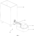
- FIG. 1 is an isometric view depicting the rotary joint unit 104 attached with the tugging unit 106 mounted onto the autonomous mobile robot (AMR) 102 which tugs the carrier 108, according to some embodiments of the present disclosure.
- FIGS. 2A-2C are isometric views of the rotary joint unit 104 attached with the tugging unit 106, according to some embodiments of the present disclosure.
- FIG. 3A is a sectional view of the rotary joint unit 104 attached with the tugging unit 106, according to some embodiments of the present disclosure.
- An automated carrier tugger 100 includes the rotary joint unit 104 attached with the tugging unit 106 mounted onto the AMR 102 which tugs the carrier 108. In an embodiment, the automated carrier tugger 100 is interchangeably referred as a tugger 100.
- the automated carrier tugger 100 is designed for tugging one or more type carriers carrying one or more types of payload.
- the carrier 108 may corresponds to one or more trailers e.g., cart, pallet carrier on wheels, roller cage, rack on wheels.
- the automated carrier tugger 100 is mounted on the autonomous mobile robot (AMR) 102 for tugging the carrier 108.
- the automated carrier tugger 100 includes the rotary joint unit 104, a swivel adaptor unit, and the tugging unit 106 for clamping the horizontal bar 602 (as depicted in FIG. 6 ) of the carrier 108.
- the rotary joint unit 104 includes the vertical fixed shaft 216, which is fixed at two ends.
- the plurality of integral pipes 212A-B are integrated with the pipe mounting plate 226 at one end.
- the plurality of integral pipes 212A-B are designed to be parallel to each other.
- the pipe mounting plate 226 is perpendicular to a ground before tightening a plurality of screws for a required torque.
- the swivel adaptor unit includes the pipe mounting plate 226 which is mounted onto the plurality of integral pipes 212A-B.
- the male spherical joint 302 is integrated with the swivel adaptor plate 312.
- the swivel adaptor plate 312 is mounted to revolve with the male spherical joint 302 to limit an amount of revolution and the swivel adaptor plate 312 touches the plurality of split connecting joint plates 308A-B.
- the tugging unit 106 for clamping the horizontal bar 602 of the carrier 108 includes the single rear clamp 518 (as depicted in FIG.
- the vertical axis slide 504 (as depicted in FIG. 5A ) is mounted to the swivel adaptor plate 312.
- the plurality of front clamps 520A-B (as depicted in FIG. 5C ) with the plurality of flanges 524A-B (as depicted in FIG. 5C ) is mounted onto the plurality of horizontal axis slides 512A-B (as depicted in FIG. 5C ) to move in a forward direction or a backward direction.
- FIG. 3B is a detailed sectional view of the rotary joint unit 104, according to some embodiments of the present disclosure.
- FIGS. 4A-4B are sectional views of the rotary joint unit 104, according to some embodiments of the present disclosure.
- the rotary joint unit 104 includes the base plate 214 mounted on the AMR 102 on which one or more parts are being mounted.
- the vertical fixed shaft 216 also referred as the rotary axis for the swivel arm 204 to perform the tugging mechanism.
- the swivel arm 204 include the plurality of integral pipes 212A-B, the pipe mounting plate 226, and the plurality of integrated semi-cylindrical clamps 224A-B.
- the swivel arm 204 rotates on the bearing housing 320 by the plurality of bearing units 314A-B.
- the plurality of bearing units 314A-B is mounted on the vertical fixed shaft 216.
- one end of vertical fixed shaft 216 is located by a hole provided on the base plate 214 and mounted over the base plate 214 at a bottom point by one or more fasteners.
- another end of the vertical fixed shaft 216 is located at top of the counterweight casting 202 and additionally supported by the plurality of bearing units 314A-B mounted on the bearing housing 320.
- There are two main elements are mounted to the bearing housing 320 i.e., the shaft gear 324 and the locking coupling 232.
- the shaft gear 324 is mounted by the spacer 322 and the locking coupling 232 is located and mounted on top of the bearing housing 320.
- the swivel arm 204 is also mounted using the plurality of semi cylindrical clamps 224A-B.
- the bottom and top end of the bearing housing 320 is engaged by the plurality of bearing units 314A-B.
- the shaft gear 324 is also located by the bearing housing 320 and mounted on the spacer 322.
- the plurality of tension springs 234A-B mounted on either side of the shaft gear 324.
- the swivel arm 204 is integrated with the plurality of tension springs 234A-B.
- on one side of the tension spring 234A is connected to one side of the shaft gear 324 which is coupled with outer diameter of the bearing unit 314A, and other side of the tension spring 234B is connected to the plurality of stand offs 238A-B.
- the plurality of stand offs 238A-B is mounted onto the base plate 214.
- the swivel arm 204 is attached with the tugging unit 106 is free to swivel overcoming a spring force when the AMR 102 is moving in at least one direction.
- the plurality of tension springs 234A-B exerts an equal tension force on the plurality of bearing units 314A-B.
- the shaft gear 324 is mounted onto the bearing housing 320.
- the bearing housing 320 is coupled with the plurality of bearing units 314A-B.
- the plurality of integrated semi cylindrical clamps 224A-B and the plurality of free semi cylindrical clamps 228A-B are mounted on the bearing housing 320.
- one end of the plurality of tension springs 234A-B is connected to the shaft gear 324 and another end is connected to the plurality of stand offs 238A-B.
- whole swiveling arm assembly are aligned in center with the AMR 102 by the plurality of tension springs 234A-B when both the shaft gear 324 and the lock coupling 232 are freely rotating on the bearing housing 320 and concentric with the vertical fixed shaft 216.
- the rotary joint unit 104 consists of the mounting bracket 236 which is mounted to the base plate 214 by one or more screws for locking mechanism.
- the lock engaging actuator 218 with the lock engager 230 is mounted to the mounting bracket 236.
- a position of the swivel arm 204 is positioned at center of the rotary joint unit 104 by the plurality of tension springs 234A-B attached between the plurality of standoffs 238A-B and the shaft gear 324 when the tugging unit 106 is at an idle position.
- the floating connector 406 hinges about the hinge point 316 i.e., a bottom point of the floating connector 406 include two pins which are sliding inside one or more slots provided in the motor mounting plate 402, a middle point of the floating connector 406 is connected to the hinge pin 408, and at top point of the floating connector 406 is connected to the lock engager 230.
- the motor 310 with the motor mounting plate 402 also include two pin holes and pivoted at both sides of the motor 310 with two pins and the L bracket 404. The two pin holes and the two pins actuate the motor 310 to swivel about the two pin holes through the floating connector 406 as the lock engager 230 operated by the lock engaging actuator 218.
- the lock engaging actuator 218 is connected to the lock engager 230
- the floating connector 406 connects between the lock engager 230 and the motor mounting plate 402 at bottom end.
- the motor 310 and the motor gear 318 are engaged into the shaft gear 324.
- the motor 310 causing the swivel arm 204 to rotate for attaining a required orientation.
- the locking coupling 232 includes a mirror teeth profile and the lock engager 230 includes an inverse teeth profile to mesh and provide a load taking lock by without transferring an additional load to the motor 310.
- the locking coupling 232 and the lock engager 230 is engaged by the lock engaging actuator 218 and the vertical axis slide 504.
- the floating connector 406 is pivoted about the hinge point 316 when the lock engaging actuator 218 operates in forward or backward direction.
- the floating connector 406 actuates the motor 310 along with the motor mounting plate 402 by a sliding contact between the motor mounting plate 402 and the floating connector 406.
- the lock engager 230 moves in a forward direction by the lock engaging actuator 218 to lock the swivel arm 204 at a particular angle.
- a point P on the motor gear 318 and a point Q on the shaft gear 324 is not connected when a point A on the lock engager 230 is locked with a point B on the locking coupling 232.
- the lock engager 230 moves in a backward direction by the lock engaging actuator 218 to enable the motor 310 to rotate the swivel arm 204 at a required angle.
- the point A on the lock engager 230 and the point B on the locking coupling 232 is not connected when a point P on the motor gear 318 is locked with a point Q on the shaft gear 324.
- the AMR 102 may rotate to some extent while the swivel arm 204 to pick the carrier 108.
- the lock engaging actuator 218 is at home position to rotate the swivel arm 204 within a required angle during forward movement.
- the point A on the lock engager 230 is not connected the point B on the locking coupling 232.
- the point P on the motor gear 318 is not connected with the point Q on the shaft gear 324.
- the lock engaging actuator 218 when the lock engaging actuator 218 is at a home position then there are no connections between the points A and B, and P and Q, and the swivel arm assembly are free to rotate and always positioned in center of the AMR 102 with help of the plurality of tension springs (e.g., two tension springs) 234A-B connected between the plurality of standoffs 238A-B and the shaft gear 324.
- the plurality of tension springs e.g., two tension springs
- three positions between AB and PQ are also achieved by using another motor instead of the lock engaging actuator 218.
- the motor 310 can rotate clockwise or anticlockwise direction operating the lock engager 230 forward or backward direction.
- the swivel arm 204 consists of at least two pipes of which one end is mounted to the pipe mounting plate 226 and another end is connected to the vertical fixed shaft 216 with help of the plurality of semi cylindrical clamps 224A-B.
- two bumpers mounted to the two pipes of the swivel arm 204 which provides a damping action for entire swivel arm assembly during rotation of arm assembly itself to prevent a sudden hitting of the arm assembly with the counterweight casting 202.
- rubber pads are attached on either side of the counterweight casting 202 which combinedly provides a cushioning effect in between the swivel arm assembly and the counterweight casting 202.
- the pipe mounting plate 226 is mounted, additionally the plurality of split connecting joint plates (e.g., two split connecting joint plates) 308A-B are also mounted to the pipe mounting plate 226.
- the plurality of spherical joints and the plurality of compression springs (e.g., four compression springs) 306A-D are connected in between the pipe mounting plate 226 and the swivel adaptor plate 312.
- the plurality of compression springs may alternatively replace with but not limited to a plurality of wave springs, and a plurality of disc springs.
- the plurality of spherical joints corresponds to the male spherical joint 302 and the female spherical joint 304.
- the swivel adaptor plate 312 is mounted free to revolve with the plurality of spherical joints caused by one or more spherical bearings, but at the same time restricted to limit an amount of revolution such that at maximum limits the swivel adaptor plate 312 touches the plurality of split connecting joint plates 308A-B.
- the two compression springs 306A-B at top position can compress more and the two compression springs 306C-D at bottom position can expand from a more compressed to a less compressed state.
- the plurality of compression springs 306A-D compress equally to bring to an equilibrium.
- the two compression springs 306A-B at the top position come to a compress less condition from a compress more condition and the two compression springs 306C-D at bottom position compress more.
- the encoder 220 is mounted above the locking coupling 232 which helps the rotary joint unit 104 to rotate the swivel arm 204 at a required angle.
- the rotary joint unit 104 is covered by the counterweight casting 202.
- the counterweight casting 202 acts as an enclosure to the rotary joint unit 104.
- the emergency switch 210 is mounted onto the counterweight casting 202 which is easily accessible during emergency to stop the rotary joint unit 104.
- the male spherical joint 302 and the female spherical joint 304 together formed as a spherical bearing mounted in between the pipe mounting plate 226 and the swivel adaptor plate 312.
- the male spherical joint 302 and the female spherical joint 304 are held together by the plurality of split connecting joint plates 308A-B.
- the plurality of split connecting joint plates 308A-B are screwed to the pipe mounting plate 226 by a plurality of fasteners.
- One end of the male spherical joint 302 is screwed to the swivel adaptor plate 312 and another spherical end is inserted into the female spherical joint 304 to provide a spherical action for the swivel adaptor plate 312 in turn to tugging mechanism.
- the spherical action is controlled by the plurality of compression springs 306A-D connected in between the pipe mounting plate 226 and the swivel adaptor plate 312.
- the rotary joint unit 104 with the swivel adaptor plate 312 is swivel about a point E.
- FIG. 5A is a right view of the tugging unit 106 to clamp the horizontal bar 602 of the carrier 108, according to some embodiments of the present disclosure.
- FIG. 5B is a front view of the tugging unit 106 to clamp the horizontal bar 602 of the carrier 108, according to some embodiments of the present disclosure.
- FIG. 5C is a top sectional view of the tugging unit 106 to clamp the horizontal bar 602 of the carrier 108, according to some embodiments of the present disclosure.
- FIG. 6 is a detailed sectional view of the hook and the plurality of spherical joints of the tugging unit 106, according to some embodiments of the present disclosure.
- the swivel adaptor plate 312 mainly consists of two drive units i.e., the vertical drive unit 502 and the horizontal drive unit 508.
- the vertical drive motor 506 slides the single rear clamp 518 and the horizontal drive unit 508 up and down direction over a vertical axis and further the horizontal drive motor 508 provides forward and backward movement for the plurality of front clamps 520A-B with the plurality of two flanges 524A-B through a horizontal axis.
- the single rear clamp 518 includes the opening bend 514 is designed to support tugging a square bar or any other profile. For example, when the AMR 102 with the tugging unit 106 goes underneath the carrier 108 to be tugged the single rear clamp 518 is moved up or down according to a height required for hook to tug the horizontal bar 602 of the carrier 108 from bottom and rear side.
- the opening bend 514 helps the tugging unit 106 to hold the horizontal bar 602 of the carrier 108easily.
- the plurality of front clamps 520A-B plate with the plurality of two flanges 524A-B moved towards the horizontal bar 602 of the carrier 108 to hold further from a side face.
- the the plurality of front clamps 520A-B with the plurality of two flanges 524A-B is a single part moved forward and backward over the plurality of the horizontal axis slides 512A-B i.e., a left horizontal axis slide and a right horizontal axis slide and a single drive unit.
- a camera 516 is mounted at front of the swivel adaptor plate 312 which support in identifying one or more positions of a hooking area and a location of the carrier 108 and provide a constant feedback to navigate the AMR 102 to a desired position during the process of tugging of the horizontal bar 602.
- the single rear clamp 518 is positioned below the horizontal bar 602 of the carrier 108 for moving the vertical axis slide 504 upwards and a flange of the single rear clamp 518 to hold a rear face of the horizontal bar 602 of the carrier 108.
- the plurality of front clamps 520A-B with the plurality of flanges 524A-B moves forward towards the carrier 108 thereby the plurality of flanges 524A-B contacts a front side of the horizontal bar 602 of the carrier 108 to establish a rigid clamping connection between the carrier 108 and the AMR 102.
- FIGS. 7A is an isometric view of an exemplary tugging unit 106 to clamp the vertical rod 802 of the carrier 108 at closed position, according to some embodiments of the present disclosure.
- FIGS. 7B is a top view of the exemplary tugging unit 106 to clamp the vertical rod 802 of the carrier 108 at the closed position, according to some embodiments of the present disclosure.
- FIGS. 7C is an isometric view of the exemplary tugging unit 106 to clamp the vertical rod 802 of the carrier 108 at open position, according to some embodiments of the present disclosure.
- FIGS. 7D is a top view of the exemplary tugging unit 106 to clamp the vertical rod 802 of the carrier 108 at the open position, according to some embodiments of the present disclosure.
- FIG. 8 is an exemplary isometric view of the tugging unit 106 which clamps the vertical rod 802 of the carrier 108, according to some embodiments of the present disclosure.
- the tugging unit 106 consists of the housing 718 for vertical rod hooking mechanism, the left hand (LH) lead screw and the right hand (RH) lead screw 706, the plurality of mounting blocks 712A-D, the plurality of rod butting elements 720A-B, the plurality of rack gears 710A-B, the plurality of pinion gears 704A-D and clamps.
- the LH lead screw and the RH lead screw 706 is mounted to the plurality of mounting blocks 712A-D at two ends and driven by a drive motor at one end.
- the left hand (LH) rack gear 710A and the right hand (RH) rack gear 710B are driven by the LH lead screw and the RH lead screw 706.
- the plurality of pinion gears 704A-D are mounted to the plurality of gear shafts 716A-D respectively which is mounted to a housing and pinions are driven by the LH rack gear 710A and the RH rack gear 710B which is travelled over the LH lead screw and the RH lead screw 706.
- the plurality of pinion gears 704A-D with the plurality of swivel clamps 714A-D are driven by the LH rack gear 710A and the RH rack gear 710B.
- the LH rack gear 710A and the RH rack gear 710B always moved in a opposite direction.
- the motor 702 actuates causing the left hand (LH) lead screw and the right hand (RH) lead screw 706 to move the left hand (LH) rack gear 710A and the right hand (RH) rack gear 710B at least one desired direction.
- the LH rack gear 710A and the RH rack gear 710B rotates the plurality of swivel clamps 714A-D to clamp and de-clamp the vertical rod 802 of the carrier 108.
- the LH rack gear 710A and the RH rack gear 710B move inwards to clamp the vertical rod 802 of the carrier 108.
- the LH rack gear 710A and the RH rack gear 710B move outwards to de-clamp the vertical rod 802 of the carrier 108.
- the plurality of rod butting elements 720A-B locates the vertical rod 802 and supports tugging of the carrier 108.
- FIG. 9 is an exemplary top view of the rotary joint unit 104 mounted onto the AMR 102 attached with the tugging unit 106 which tugs the carrier 108, according to some embodiments of the present disclosure.
- the automated carrier tugger is designed with the rotary joint unit 104 mounted onto the AMR 102 attached with the tugging unit 106 which tugs the carrier 108 carrying the payload.
- the swivel arm 204 is at an angular orientation in a range of +/-90 deg except 0 deg home position to automatically attach a cart.
- the embodiments of present disclosure herein address unresolved problem of one or more complications that arise while designing a tugging unit for better transportation of loads.
- the embodiments of present disclosure thus provide the automated carrier tugger which is designed with the rotary joint unit attached with the tugging unit mounted onto the autonomous mobile robot (AMR) to tug the carrier.
- the embodiments herein further provide an ability to come back to home position by itself during tugging at same orientation of the carrier and without external power control.
- the embodiments of present disclosure herein provide the automated carrier tugger which is customizable to work for one or more cart types and programming the design can be easily performed.
- the automated carrier tugger have an ability to pull roll cage containers with a horizontal bar at below the cart.
- the automated carrier tugger have an ability to pull roll cage containers with vertical bars in the front of the cart.
- the embodiments herein can comprise hardware and software elements.
- the embodiments that are implemented in software include but are not limited to, firmware, resident software, microcode, etc.
- the functions performed by various components described herein may be implemented in other components or combinations of other components.
- a computer-usable or computer readable medium can be any apparatus that can comprise, store, communicate, propagate, or transport the program for use by or in connection with the instruction execution system, apparatus, or device.
- a computer-readable storage medium refers to any type of physical memory on which information or data readable by a processor may be stored.
- a computer-readable storage medium may store instructions for execution by one or more processors, including instructions for causing the processor(s) to perform steps or stages consistent with the embodiments described herein.
- the term "computer-readable medium” should be understood to include tangible items and exclude carrier waves and transient signals, i.e., be non-transitory. Examples include random access memory (RAM), read-only memory (ROM), volatile memory, nonvolatile memory, hard drives, CD ROMs, DVDs, flash drives, disks, and any other known physical storage media.
Description
- The present application claims priority from
Indian patent application no. 202021040100, filed on September 16, 2020 - The disclosure herein generally relates to a robotics system, and, more particularly, to an automated carrier tugger, which includes a rotary joint unit attached with a tugging unit mounted on an autonomous mobile robot (AMR) for tugging a carrier carrying a payload.
- Industry environment is transforming with traditional warehouses into smart warehouses. Trailers are unpowered vehicles in the warehouse with varied applications of material handling including picking and transport. For example, the varied applications could be bins on wheels, pallets on wheels, carts, trolleys, Racks on wheels, automotive assemblies mounted on wheels. Typical industry practice most commonly observed is to manually attach the unpowered trailer to a powered vehicle. The powered vehicle can be fully autonomous robotic vehicle or semi-automated like automated guided vehicle or manually operated tugger trucks. The fully autonomous robotic type of powered vehicle, wherein the vehicle attaches itself automatically to the unpowered trailer are hardly a few across globe. Further, there are very limited designs existing with lesser functions and mechanisms leading to complex manipulations which lead to complex programming. Further, while designing the hook corresponding with latching area resulting in a design limitation for gaining a specific orientation with respect to the powered vehicle and orientation of the unpowered trailer. The document
WO 2016/165721 A1 discloses an autonomous mobile robot (AMR) for tugging a carrier. - Embodiments of the present disclosure present technological improvements as solutions to one or more of the above-mentioned technical problems recognized by the inventors in conventional systems. The invention is defined by the appended claims. According to the invention, an autonomous mobile robot (AMR) for tugging a carrier with an automated carrier tugger mounted thereon is provided. The automated carrier tugger includes a rotary joint unit, a swivel adaptor unit, and a tugging unit for clamping a horizontal bar. The rotary joint unit includes a vertical fixed shaft, fixed at two ends; and a plurality of integral pipes, integrated with a pipe mounting plate at one end. On one end is mounted to a base plate, and another end is fixed to a counterweight housing to house a swivel arm. The plurality of integral pipes are designed to be parallel to each other. The pipe mounting plate is perpendicular to a ground before tightening a plurality of screws for a required torque. The swivel adaptor unit includes the pipe mounting plate, which is mounted onto the plurality of integral pipes; and a male spherical joint, integrated with a swivel adaptor plate. The pipe mounting plate and a plurality of split connecting joint plates are joined together to hold a female spherical joint. The swivel adaptor plate is mounted to revolve with the male spherical joint to limit an amount of revolution and the swivel adaptor plate touches the plurality of split connecting joint plates. The tugging unit for clamping the horizontal bar includes a single rear clamp, mounted onto a vertical axis slide; and a plurality of front clamps with a plurality of flanges, mounted onto a plurality of horizontal axis slides to move in a forward direction or a backward direction. The vertical axis slide is mounted to the swivel adaptor plate.
- The swivel arm includes the plurality of integral pipes, the pipe mounting plate, and the plurality of integrated semi-cylindrical clamps. The swivel arm rotates on a bearing housing via a plurality of bearing units. The plurality of bearing units are mounted on the vertical fixed shaft. The plurality of integral pipes are integrated with the plurality of bearing units at one end and the pipe mounting plate at another end to form the swivel arm. The swivel arm is integrated with a plurality of tension springs. One side of a tension spring is connected to one side of a shaft gear which is coupled with outer diameter of the bearing unit, and other side of a tension spring is connected to a plurality of stand offs. The plurality of stand offs is mounted onto the base plate.
- The swivel arm attached with the tugging unit is free to swivel overcoming a spring force when the AMR is moving in at least one direction. The plurality of tension springs exerts an equal tension force on the plurality of bearing units. The shaft gear is mounted onto the bearing housing. The bearing housing is coupled with the plurality of bearing units. The plurality of integrated semi cylindrical clamps and a plurality of free semi cylindrical clamps are mounted on the bearing housing. A motor and a motor gear are engaged into the shaft gear. The motor operates causing the swivel arm to rotate for attaining a required orientation.
- A locking coupling include a mirror teeth profile and a lock engager includes an inverse teeth profile to mesh and provide a load taking lock by without transferring an additional load to the motor. The locking coupling and the lock engager is engaged by a lock engaging actuator and the vertical axis slide. The lock engaging actuator operates in forward or backward direction to pivot a floating connector about a hinge point. The floating connector actuates the motor along with a motor mounting plate by a sliding contact between the motor mounting plate and the floating connector.
- The lock engager moves in a forward direction by the lock engaging actuator to lock the swivel arm at a particular angle. A point P on the motor gear and a point Q on the shaft gear is not connected when a point A on the lock engager is locked with a point B on the locking coupling. The lock engager moves in a backward direction by the lock engaging actuator to enable the motor to rotate the swivel arm at a required angle. The point A on the lock engager and the point B on the locking coupling is not connected when a point P on the motor gear is locked with a point Q on the shaft gear. The lock engaging actuator is at home position to rotate the swivel arm within a required angle during forward movement. The point A on the lock engager is not connected the point B on the locking coupling. The point P on the motor gear is not connected with the point Q on the shaft gear.
- A position of the swivel arm is positioned at center of the rotary joint unit by the plurality of tension springs attached between the plurality of standoffs and the shaft gear when the tugging unit is at an idle position. The single rear clamp is positioned below the horizontal bar for moving the vertical axis slide upwards and a flange of the single rear clamp to hold a rear face of the horizontal bar of the carrier. The plurality of front clamps with the plurality of flanges moves forward towards the carrier thereby the plurality of flanges contact a front side of the horizontal bar to establish a rigid clamping connection between the carrier and the AMR.
- The tugging unit for clamping a vertical rod of the carrier includes a motor actuates causing a left hand (LH) lead screw and a right hand (RH) lead screw to move a left hand (LH) rack gear and a right hand (RH) rack gear at least one desired direction. The LH rack gear and the RH rack gear rotate a plurality of swivel clamps to clamp and de-clamp a vertical rod of the carrier. The LH rack gear and the RH rack gear move inwards to clamp the vertical rod of the carrier. The LH rack gear and the RH rack gear move outwards to de-clamp the vertical rod of the carrier. A plurality of rod butting elements locates the vertical rod and supports tugging of the carrier.
- It is to be understood that both the foregoing general description and the following detailed description are exemplary and explanatory only and are not restrictive of the invention, as claimed.
- The accompanying drawings, which are incorporated in and constitute a part of this disclosure, illustrate exemplary embodiments and, together with the description, serve to explain the disclosed principles:
-
FIG. 1 is an isometric view depicting a rotary joint unit attached with a tugging unit mounted onto an autonomous mobile robot (AMR) which tugs a carrier, according to some embodiments of the present disclosure. -
FIGS. 2A-2C are isometric views of the rotary joint unit attached with the tugging unit, according to some embodiments of the present disclosure. -
FIG. 3A is a sectional view of the rotary joint unit attached with the tugging unit, according to some embodiments of the present disclosure. -
FIG. 3B is a detailed sectional view of the rotary joint unit, according to some embodiments of the present disclosure. -
FIGS. 4A-4B are sectional views of the rotary joint unit, according to some embodiments of the present disclosure. -
FIG. 5A is a right side view of the tugging unit to clamp a horizontal bar of the carrier, according to some embodiments of the present disclosure. -
FIG. 5B is a front view of the tugging unit to clamp the horizontal bar of the carrier, according to some embodiments of the present disclosure. -
FIG. 5C is a top sectional view of the tugging unit to clamp the horizontal bar of the carrier, according to some embodiments of the present disclosure. -
FIG. 6 is a detailed sectional view of a hook and plurality of spherical joints of the tugging unit, according to some embodiments of the present disclosure. -
FIGS. 7A is an isometric view of an exemplary tugging unit to clamp a vertical rod of the carrier at closed position, according to some embodiments of the present disclosure. -
FIGS. 7B is a top view of the exemplary tugging unit to clamp the vertical rod of the carrier at the closed position, according to some embodiments of the present disclosure. -
FIGS. 7C is an isometric view of the exemplary tugging unit to clamp the vertical rod of the carrier at open position, according to some embodiments of the present disclosure. -
FIGS. 7D is a top view of the exemplary tugging unit to clamp the vertical rod of the carrier at the open position, according to some embodiments of the present disclosure. -
FIG. 8 is an exemplary isometric view of the tugging unit which clamps the vertical rod of the carrier, according to some embodiments of the present disclosure. -
FIG. 9 is an exemplary top view of the rotary joint unit mounted onto the autonomous mobile robot (AMR) attached with the tugging unit which tugs the carrier, according to some embodiments of the present disclosure. - Exemplary embodiments are described with reference to the accompanying drawings. In the figures, the left-most digit(s) of a reference number identifies the figure in which the reference number first appears. Wherever convenient, the same reference numbers are used throughout the drawings to refer to the same or like parts. While examples and features of disclosed principles are described herein, modifications, adaptations, and other implementations are possible without departing from the scope of the disclosed embodiments.
- Embodiments of the present disclosure provide an automated carrier tugger is designed for tugging a carrier carrying a payload at warehouses and logistics areas. The automated carrier tugger consists of a rotary joint unit attached with a tugging unit. The automated carrier tugger is mounted on to an autonomous mobile robot (AMR) or an automated guided vehicle (AGV). The automated carrier tugger is designed for tugging one or more carriers carrying one or more payloads. For example, one or more carriers are a cart, a pallet carrier on wheels, a roller cage, a rack on wheels. The tugging unit is designed to clamp one or more carriers in a one or more positions i.e., a horizontal bar and a vertical rod.
- Referring now to the drawings, and more particularly to
FIGS. 1 through 9 , where similar reference characters denote corresponding features consistently throughout the figures, there are shown preferred embodiments and these embodiments are described in the context of the following exemplary system and/or method. - Reference numerals of one or more components of an automated carrier tugger, which includes the rotary joint unit attached with the tugging unit mounted on the autonomous mobile robot (AMR) for tugging the carrier as depicted in the
FIGS. 1 through 9 are provided in Table 1 below for ease of description.TABLE 1 S.NO NAME OF COMPONENT REFERENCE NUMERALS 1 Carrier tugger 100 2 Autonomous Mobile Robot (AMR) / Automated guided vehicle (AGV) 102 3 Rotary joint Unit 104 4 Tugging unit 106 5 Carrier 108 6 Counterweight casting 202 7 Swivel arm 204 8 Plurality of protective covers 206A-C 9 Plurality of rubber pads 208A-B 10 Emergency switch 210 11 Plurality of integral pipes 212A-B 12 Base plate 214 13 Vertical fixed shaft 216 14 Lock engaging actuator 218 15 Encoder 220 16 Plurality of bumpers 222A-B 17 Plurality of integrated semi-cylindrical clamps 224A-B 18 Pipe mounting plate 226 19 Plurality of free semi cylindrical clamps 228A-B 20 Lock engager 230 21 Locking coupling 232 22 Plurality of tension springs 234A-B 23 Mounting Bracket 236 24 Plurality of stand offs 23 8A-B 25 Male spherical joint 302 26 Female spherical joint 304 27 Plurality of compression springs 306A-D 28 Plurality of split connecting joint plates 308A-B 29 Motor for locking mechanism 310 30 Swivel adaptor plate 312 31 Plurality of bearing units 314A-B 32 Hinge point for floating connector 316 33 Motor gear 318 34 Bearing housing 320 35 Spacer 322 36 Shaft gear 324 37 Motor mounting plate 402 38 L Bracket 404 39 Floating connector 406 40 Hinge pin 408 41 Motor hinge point 410 42 Vertical drive unit 502 43 Vertical axis slide 504 44 Vertical drive motor 506 45 Horizontal drive unit 508 46 Horizontal drive motor 510 47 Plurality of horizontal axis slides 512A-B 48 Opening bend 514 49 Camera 516 50 Single rear clamp 518 51 Plurality of front clamp plates 520A-B 52 Plurality of gears 522A-B 53 Plurality of flanges 524A-B 54 Horizontal bar of a cart 602 55 Motor for vertical rod hooking mechanism 702 56 Plurality of pinion gears 704A-D 57 Left hand (LH) and right hand (RH) Lead screw 706 58 Mounting plate for the spherical joint 708 59 Left hand (LH) rack gear 710A 60 Right hand (RH) rack gear 710B 61 Plurality of mounting blocks 712A-D 62 Plurality of swivel clamps 714A-D 63 Plurality of gear shafts 716A-D 64 Housing for vertical rod hooking mechanism 718 65 Plurality of Rod butting elements 720A-B 66 Vertical rod 802 -
FIG. 1 is an isometric view depicting the rotaryjoint unit 104 attached with thetugging unit 106 mounted onto the autonomous mobile robot (AMR) 102 which tugs thecarrier 108, according to some embodiments of the present disclosure.FIGS. 2A-2C are isometric views of the rotaryjoint unit 104 attached with thetugging unit 106, according to some embodiments of the present disclosure.FIG. 3A is a sectional view of the rotaryjoint unit 104 attached with thetugging unit 106, according to some embodiments of the present disclosure. Anautomated carrier tugger 100 includes the rotaryjoint unit 104 attached with thetugging unit 106 mounted onto theAMR 102 which tugs thecarrier 108. In an embodiment, theautomated carrier tugger 100 is interchangeably referred as atugger 100. In an embodiment, theautomated carrier tugger 100 is designed for tugging one or more type carriers carrying one or more types of payload. In at least one embodiment, thecarrier 108 may corresponds to one or more trailers e.g., cart, pallet carrier on wheels, roller cage, rack on wheels. Theautomated carrier tugger 100 is mounted on the autonomous mobile robot (AMR) 102 for tugging thecarrier 108. Theautomated carrier tugger 100 includes the rotaryjoint unit 104, a swivel adaptor unit, and thetugging unit 106 for clamping the horizontal bar 602 (as depicted inFIG. 6 ) of thecarrier 108. The rotaryjoint unit 104 includes the vertical fixedshaft 216, which is fixed at two ends. One end is mounted to abase plate 214, and another end is fixed to acounterweight housing 202 to house aswivel arm 204. The plurality ofintegral pipes 212A-B are integrated with thepipe mounting plate 226 at one end. The plurality ofintegral pipes 212A-B are designed to be parallel to each other. Thepipe mounting plate 226 is perpendicular to a ground before tightening a plurality of screws for a required torque. - The swivel adaptor unit includes the
pipe mounting plate 226 which is mounted onto the plurality ofintegral pipes 212A-B. Thepipe mounting plate 226 and the plurality of split connectingjoint plates 308A-B joined to hold the female spherical joint 304. The male spherical joint 302 is integrated with theswivel adaptor plate 312. Theswivel adaptor plate 312 is mounted to revolve with the male spherical joint 302 to limit an amount of revolution and theswivel adaptor plate 312 touches the plurality of split connectingjoint plates 308A-B. Thetugging unit 106 for clamping thehorizontal bar 602 of thecarrier 108 includes the single rear clamp 518 (as depicted inFIG. 5C ) is mounted onto avertical axis slide 504. The vertical axis slide 504 (as depicted inFIG. 5A ) is mounted to theswivel adaptor plate 312. The plurality of front clamps 520A-B (as depicted inFIG. 5C ) with the plurality offlanges 524A-B (as depicted inFIG. 5C ) is mounted onto the plurality of horizontal axis slides 512A-B (as depicted inFIG. 5C ) to move in a forward direction or a backward direction. -
FIG. 3B is a detailed sectional view of the rotaryjoint unit 104, according to some embodiments of the present disclosure.FIGS. 4A-4B are sectional views of the rotaryjoint unit 104, according to some embodiments of the present disclosure. The rotaryjoint unit 104 includes thebase plate 214 mounted on theAMR 102 on which one or more parts are being mounted. The vertical fixedshaft 216 also referred as the rotary axis for theswivel arm 204 to perform the tugging mechanism. Theswivel arm 204 include the plurality ofintegral pipes 212A-B, thepipe mounting plate 226, and the plurality of integrated semi-cylindrical clamps 224A-B. Theswivel arm 204 rotates on the bearinghousing 320 by the plurality of bearingunits 314A-B. The plurality of bearingunits 314A-B is mounted on the vertical fixedshaft 216. The plurality ofintegral pipes 212A-B integrated with the plurality of bearingunits 314A-B at one end and thepipe mounting plate 226 integrated at another end to form theswivel arm 204. - In an embodiment, one end of vertical fixed
shaft 216 is located by a hole provided on thebase plate 214 and mounted over thebase plate 214 at a bottom point by one or more fasteners. In an embodiment, another end of the vertical fixedshaft 216 is located at top of the counterweight casting 202 and additionally supported by the plurality of bearingunits 314A-B mounted on the bearinghousing 320. There are two main elements are mounted to the bearinghousing 320 i.e., theshaft gear 324 and the lockingcoupling 232. Theshaft gear 324 is mounted by thespacer 322 and the lockingcoupling 232 is located and mounted on top of the bearinghousing 320. Additionally, theswivel arm 204 is also mounted using the plurality of semi cylindrical clamps 224A-B. The bottom and top end of the bearinghousing 320 is engaged by the plurality of bearingunits 314A-B. In an embodiment, theshaft gear 324 is also located by the bearinghousing 320 and mounted on thespacer 322. The plurality of tension springs 234A-B mounted on either side of theshaft gear 324. - The
swivel arm 204 is integrated with the plurality of tension springs 234A-B. In an embodiment, on one side of thetension spring 234A is connected to one side of theshaft gear 324 which is coupled with outer diameter of thebearing unit 314A, and other side of the tension spring 234B is connected to the plurality ofstand offs 238A-B. The plurality ofstand offs 238A-B is mounted onto thebase plate 214. Theswivel arm 204 is attached with thetugging unit 106 is free to swivel overcoming a spring force when theAMR 102 is moving in at least one direction. The plurality of tension springs 234A-B exerts an equal tension force on the plurality of bearingunits 314A-B. Theshaft gear 324 is mounted onto the bearinghousing 320. The bearinghousing 320 is coupled with the plurality of bearingunits 314A-B. The plurality of integrated semi cylindrical clamps 224A-B and the plurality of free semi cylindrical clamps 228A-B are mounted on the bearinghousing 320. In an embodiment, one end of the plurality of tension springs 234A-B is connected to theshaft gear 324 and another end is connected to the plurality ofstand offs 238A-B. - In an embodiment, whole swiveling arm assembly are aligned in center with the
AMR 102 by the plurality of tension springs 234A-B when both theshaft gear 324 and thelock coupling 232 are freely rotating on the bearinghousing 320 and concentric with the vertical fixedshaft 216. The rotaryjoint unit 104 consists of the mountingbracket 236 which is mounted to thebase plate 214 by one or more screws for locking mechanism. Thelock engaging actuator 218 with thelock engager 230 is mounted to the mountingbracket 236. A position of theswivel arm 204 is positioned at center of the rotaryjoint unit 104 by the plurality of tension springs 234A-B attached between the plurality ofstandoffs 238A-B and theshaft gear 324 when thetugging unit 106 is at an idle position. - The floating
connector 406 hinges about thehinge point 316 i.e., a bottom point of the floatingconnector 406 include two pins which are sliding inside one or more slots provided in themotor mounting plate 402, a middle point of the floatingconnector 406 is connected to thehinge pin 408, and at top point of the floatingconnector 406 is connected to thelock engager 230. In an embodiment, themotor 310 with themotor mounting plate 402 also include two pin holes and pivoted at both sides of themotor 310 with two pins and theL bracket 404. The two pin holes and the two pins actuate themotor 310 to swivel about the two pin holes through the floatingconnector 406 as thelock engager 230 operated by thelock engaging actuator 218. - In an embodiment, as the
lock engaging actuator 218 is connected to thelock engager 230, and the floatingconnector 406 connects between thelock engager 230 and themotor mounting plate 402 at bottom end. Themotor 310 and themotor gear 318 are engaged into theshaft gear 324. Themotor 310 causing theswivel arm 204 to rotate for attaining a required orientation. The lockingcoupling 232 includes a mirror teeth profile and thelock engager 230 includes an inverse teeth profile to mesh and provide a load taking lock by without transferring an additional load to themotor 310. The lockingcoupling 232 and thelock engager 230 is engaged by thelock engaging actuator 218 and thevertical axis slide 504. The floatingconnector 406 is pivoted about thehinge point 316 when thelock engaging actuator 218 operates in forward or backward direction. The floatingconnector 406 actuates themotor 310 along with themotor mounting plate 402 by a sliding contact between themotor mounting plate 402 and the floatingconnector 406. - The
lock engager 230 moves in a forward direction by thelock engaging actuator 218 to lock theswivel arm 204 at a particular angle. A point P on themotor gear 318 and a point Q on theshaft gear 324 is not connected when a point A on thelock engager 230 is locked with a point B on the lockingcoupling 232. Thelock engager 230 moves in a backward direction by thelock engaging actuator 218 to enable themotor 310 to rotate theswivel arm 204 at a required angle. The point A on thelock engager 230 and the point B on the lockingcoupling 232 is not connected when a point P on themotor gear 318 is locked with a point Q on theshaft gear 324. In an embodiment, to orient theswivel arm 204 and to engage with thecarrier 108 when maneuvering space is limited and theAMR 102 is unable to orient parallel to thecarrier 108, then theAMR 102 may rotate to some extent while theswivel arm 204 to pick thecarrier 108. Thelock engaging actuator 218 is at home position to rotate theswivel arm 204 within a required angle during forward movement. The point A on thelock engager 230 is not connected the point B on the lockingcoupling 232. The point P on themotor gear 318 is not connected with the point Q on theshaft gear 324. - In an embodiment, when the
lock engaging actuator 218 is at a home position then there are no connections between the points A and B, and P and Q, and the swivel arm assembly are free to rotate and always positioned in center of theAMR 102 with help of the plurality of tension springs (e.g., two tension springs) 234A-B connected between the plurality ofstandoffs 238A-B and theshaft gear 324. In an embodiment, three positions between AB and PQ are also achieved by using another motor instead of thelock engaging actuator 218. Themotor 310 can rotate clockwise or anticlockwise direction operating thelock engager 230 forward or backward direction. - The
swivel arm 204 consists of at least two pipes of which one end is mounted to thepipe mounting plate 226 and another end is connected to the vertical fixedshaft 216 with help of the plurality of semi cylindrical clamps 224A-B. In an embodiment, two bumpers mounted to the two pipes of theswivel arm 204 which provides a damping action for entire swivel arm assembly during rotation of arm assembly itself to prevent a sudden hitting of the arm assembly with the counterweight casting 202. In an embodiment, rubber pads are attached on either side of the counterweight casting 202 which combinedly provides a cushioning effect in between the swivel arm assembly and the counterweight casting 202. In an embodiment, other end of the swivel arm assembly, thepipe mounting plate 226 is mounted, additionally the plurality of split connecting joint plates (e.g., two split connecting joint plates) 308A-B are also mounted to thepipe mounting plate 226. - The plurality of spherical joints and the plurality of compression springs (e.g., four compression springs) 306A-D are connected in between the
pipe mounting plate 226 and theswivel adaptor plate 312. In an embodiment, the plurality of compression springs may alternatively replace with but not limited to a plurality of wave springs, and a plurality of disc springs. In an embodiment, the plurality of spherical joints corresponds to the male spherical joint 302 and the female spherical joint 304. Theswivel adaptor plate 312 is mounted free to revolve with the plurality of spherical joints caused by one or more spherical bearings, but at the same time restricted to limit an amount of revolution such that at maximum limits theswivel adaptor plate 312 touches the plurality of split connectingjoint plates 308A-B. In an embodiment, while climbing a ramp, the two compression springs 306A-B at top position can compress more and the two compression springs 306C-D at bottom position can expand from a more compressed to a less compressed state. In an embodiment, while moving on an even floor without ramps, small bumps, the plurality of compression springs 306A-D compress equally to bring to an equilibrium. In an embodiment, while moving down the ramp, at situation when theAMR 102 has already climbed down and on the even floor and thecarrier 108 is still climbing down, the two compression springs 306A-B at the top position come to a compress less condition from a compress more condition and the two compression springs 306C-D at bottom position compress more. - The
encoder 220 is mounted above the lockingcoupling 232 which helps the rotaryjoint unit 104 to rotate theswivel arm 204 at a required angle. In an embodiment, the rotaryjoint unit 104 is covered by the counterweight casting 202. In an embodiment, the counterweight casting 202 acts as an enclosure to the rotaryjoint unit 104. Theemergency switch 210 is mounted onto the counterweight casting 202 which is easily accessible during emergency to stop the rotaryjoint unit 104. The male spherical joint 302 and the female spherical joint 304 together formed as a spherical bearing mounted in between thepipe mounting plate 226 and theswivel adaptor plate 312. The male spherical joint 302 and the female spherical joint 304 are held together by the plurality of split connectingjoint plates 308A-B. The plurality of split connectingjoint plates 308A-B are screwed to thepipe mounting plate 226 by a plurality of fasteners. One end of the male spherical joint 302 is screwed to theswivel adaptor plate 312 and another spherical end is inserted into the female spherical joint 304 to provide a spherical action for theswivel adaptor plate 312 in turn to tugging mechanism. In an embodiment, the spherical action is controlled by the plurality of compression springs 306A-D connected in between thepipe mounting plate 226 and theswivel adaptor plate 312. The rotaryjoint unit 104 with theswivel adaptor plate 312 is swivel about a point E. -
FIG. 5A is a right view of thetugging unit 106 to clamp thehorizontal bar 602 of thecarrier 108, according to some embodiments of the present disclosure.FIG. 5B is a front view of thetugging unit 106 to clamp thehorizontal bar 602 of thecarrier 108, according to some embodiments of the present disclosure.FIG. 5C is a top sectional view of thetugging unit 106 to clamp thehorizontal bar 602 of thecarrier 108, according to some embodiments of the present disclosure.FIG. 6 is a detailed sectional view of the hook and the plurality of spherical joints of thetugging unit 106, according to some embodiments of the present disclosure. Theswivel adaptor plate 312 mainly consists of two drive units i.e., thevertical drive unit 502 and thehorizontal drive unit 508. Thevertical drive motor 506 slides the singlerear clamp 518 and thehorizontal drive unit 508 up and down direction over a vertical axis and further thehorizontal drive motor 508 provides forward and backward movement for the plurality of front clamps 520A-B with the plurality of twoflanges 524A-B through a horizontal axis. The singlerear clamp 518 includes theopening bend 514 is designed to support tugging a square bar or any other profile. For example, when theAMR 102 with thetugging unit 106 goes underneath thecarrier 108 to be tugged the singlerear clamp 518 is moved up or down according to a height required for hook to tug thehorizontal bar 602 of thecarrier 108 from bottom and rear side. - The
opening bend 514 helps thetugging unit 106 to hold thehorizontal bar 602 of the carrier 108easily. In an embodiment, once the bottom side is idle then the plurality of front clamps 520A-B plate with the plurality of twoflanges 524A-B moved towards thehorizontal bar 602 of thecarrier 108 to hold further from a side face. The the plurality of front clamps 520A-B with the plurality of twoflanges 524A-B is a single part moved forward and backward over the plurality of the horizontal axis slides 512A-B i.e., a left horizontal axis slide and a right horizontal axis slide and a single drive unit. Acamera 516 is mounted at front of theswivel adaptor plate 312 which support in identifying one or more positions of a hooking area and a location of thecarrier 108 and provide a constant feedback to navigate theAMR 102 to a desired position during the process of tugging of thehorizontal bar 602. The singlerear clamp 518 is positioned below thehorizontal bar 602 of thecarrier 108 for moving thevertical axis slide 504 upwards and a flange of the singlerear clamp 518 to hold a rear face of thehorizontal bar 602 of thecarrier 108. The plurality of front clamps 520A-B with the plurality offlanges 524A-B moves forward towards thecarrier 108 thereby the plurality offlanges 524A-B contacts a front side of thehorizontal bar 602 of thecarrier 108 to establish a rigid clamping connection between thecarrier 108 and theAMR 102. -
FIGS. 7A is an isometric view of anexemplary tugging unit 106 to clamp thevertical rod 802 of thecarrier 108 at closed position, according to some embodiments of the present disclosure.FIGS. 7B is a top view of theexemplary tugging unit 106 to clamp thevertical rod 802 of thecarrier 108 at the closed position, according to some embodiments of the present disclosure.FIGS. 7C is an isometric view of theexemplary tugging unit 106 to clamp thevertical rod 802 of thecarrier 108 at open position, according to some embodiments of the present disclosure.FIGS. 7D is a top view of theexemplary tugging unit 106 to clamp thevertical rod 802 of thecarrier 108 at the open position, according to some embodiments of the present disclosure.FIG. 8 is an exemplary isometric view of thetugging unit 106 which clamps thevertical rod 802 of thecarrier 108, according to some embodiments of the present disclosure. - The
tugging unit 106 consists of thehousing 718 for vertical rod hooking mechanism, the left hand (LH) lead screw and the right hand (RH)lead screw 706, the plurality of mountingblocks 712A-D, the plurality ofrod butting elements 720A-B, the plurality of rack gears 710A-B, the plurality of pinion gears 704A-D and clamps. The LH lead screw and theRH lead screw 706 is mounted to the plurality of mountingblocks 712A-D at two ends and driven by a drive motor at one end. The left hand (LH)rack gear 710A and the right hand (RH)rack gear 710B are driven by the LH lead screw and theRH lead screw 706. The plurality of pinion gears 704A-D are mounted to the plurality ofgear shafts 716A-D respectively which is mounted to a housing and pinions are driven by theLH rack gear 710A and theRH rack gear 710B which is travelled over the LH lead screw and theRH lead screw 706. The plurality of pinion gears 704A-D with the plurality of swivel clamps 714A-D are driven by theLH rack gear 710A and theRH rack gear 710B. TheLH rack gear 710A and theRH rack gear 710B always moved in a opposite direction. Themotor 702 actuates causing the left hand (LH) lead screw and the right hand (RH)lead screw 706 to move the left hand (LH)rack gear 710A and the right hand (RH)rack gear 710B at least one desired direction. TheLH rack gear 710A and theRH rack gear 710B rotates the plurality of swivel clamps 714A-D to clamp and de-clamp thevertical rod 802 of thecarrier 108. TheLH rack gear 710A and theRH rack gear 710B move inwards to clamp thevertical rod 802 of thecarrier 108. TheLH rack gear 710A and theRH rack gear 710B move outwards to de-clamp thevertical rod 802 of thecarrier 108. The plurality ofrod butting elements 720A-B locates thevertical rod 802 and supports tugging of thecarrier 108. -
FIG. 9 is an exemplary top view of the rotaryjoint unit 104 mounted onto theAMR 102 attached with thetugging unit 106 which tugs thecarrier 108, according to some embodiments of the present disclosure. The automated carrier tugger is designed with the rotaryjoint unit 104 mounted onto theAMR 102 attached with thetugging unit 106 which tugs thecarrier 108 carrying the payload. In an embodiment, theswivel arm 204 is at an angular orientation in a range of +/-90 deg except 0 deg home position to automatically attach a cart. - The embodiments of present disclosure herein address unresolved problem of one or more complications that arise while designing a tugging unit for better transportation of loads. The embodiments of present disclosure thus provide the automated carrier tugger which is designed with the rotary joint unit attached with the tugging unit mounted onto the autonomous mobile robot (AMR) to tug the carrier. Moreover, the embodiments herein further provide an ability to come back to home position by itself during tugging at same orientation of the carrier and without external power control. The embodiments of present disclosure herein provide the automated carrier tugger which is customizable to work for one or more cart types and programming the design can be easily performed. The automated carrier tugger have an ability to pull roll cage containers with a horizontal bar at below the cart. Also, the automated carrier tugger have an ability to pull roll cage containers with vertical bars in the front of the cart.
- The written description describes the subject matter herein to enable any person skilled in the art to make and use the embodiments..
- The embodiments herein can comprise hardware and software elements. The embodiments that are implemented in software include but are not limited to, firmware, resident software, microcode, etc. The functions performed by various components described herein may be implemented in other components or combinations of other components. For the purposes of this description, a computer-usable or computer readable medium can be any apparatus that can comprise, store, communicate, propagate, or transport the program for use by or in connection with the instruction execution system, apparatus, or device.
- The illustrated steps are set out to explain the exemplary embodiments shown, and it should be anticipated that ongoing technological development will change the manner in which particular functions are performed. These examples are presented herein for purposes of illustration, and not limitation. Further, the boundaries of the functional building blocks have been arbitrarily defined herein for the convenience of the description. Alternative boundaries can be defined so long as the specified functions and relationships thereof are appropriately performed. Alternatives (including equivalents, extensions, variations, deviations, etc., of those described herein) will be apparent to persons skilled in the relevant art(s) based on the teachings contained herein. Such alternatives fall within the scope of the disclosed embodiments. Also, the words "comprising," "having," "containing," and "including," and other similar forms are intended to be equivalent in meaning and be open ended in that an item or items following any one of these words is not meant to be an exhaustive listing of such item or items, or meant to be limited to only the listed item or items. It must also be noted that as used herein and in the appended claims, the singular forms "a," "an," and "the" include plural references unless the context clearly dictates otherwise.
- Furthermore, one or more computer-readable storage media may be utilized in implementing embodiments consistent with the present disclosure. A computer-readable storage medium refers to any type of physical memory on which information or data readable by a processor may be stored. Thus, a computer-readable storage medium may store instructions for execution by one or more processors, including instructions for causing the processor(s) to perform steps or stages consistent with the embodiments described herein. The term "computer-readable medium" should be understood to include tangible items and exclude carrier waves and transient signals, i.e., be non-transitory. Examples include random access memory (RAM), read-only memory (ROM), volatile memory, nonvolatile memory, hard drives, CD ROMs, DVDs, flash drives, disks, and any other known physical storage media.
- It is intended that the disclosure and examples be considered as exemplary only, with a true scope of disclosed embodiments being indicated by the following claims.
Claims (15)
- An autonomous mobile robot (AMR) (102) for tugging a carrier (108) with an automated carrier tugger (100) mounted thereon, wherein the automated carrier tugger (100) comprising:a rotary joint unit (104), comprising:a vertical fixed shaft (216), fixed at two ends, wherein one end is mounted to a base plate (214), and another end is fixed to a counterweight housing (202) to house a swivel arm (204); anda plurality of integral pipes (212A-B), integrated with a pipe mounting plate (226) at one end, wherein the plurality of integral pipes (212A-B) are designed to be parallel to each other, wherein the pipe mounting plate (226) is perpendicular to a ground before tightening a plurality of screws for a required torque;a swivel adaptor unit, comprising:the pipe mounting plate (226), which is mounted onto the plurality of integral pipes (212A-B), wherein the pipe mounting plate (226) and a plurality of split connecting joint plates (308A-B) are joined to hold a female spherical joint (304); anda male spherical joint (302), integrated with a swivel adaptor plate (312), wherein the swivel adaptor plate (312) is mounted to revolve with the male spherical joint (302) to limit an amount of revolution and the swivel adaptor plate (312) touches the plurality of split connecting joint plates (308A-B); anda tugging unit (106) for clamping a horizontal bar (602), comprising:a single rear clamp (518), mounted onto a vertical axis slide (504), wherein the vertical axis slide (504) is mounted to the swivel adaptor plate (312); anda plurality of front clamps (520A-B) with a plurality of flanges (524A-B), mounted onto a plurality of horizontal axis slides (512A-B) to move in a forward direction or a backward direction.
- The autonomous mobile robot (AMR) as claimed in claim 1, wherein the swivel arm (204) comprises the plurality of integral pipes (212A-B), the pipe mounting plate (226), and the plurality of integrated semi-cylindrical clamps (224A-B), wherein the swivel arm (204) rotates on a bearing housing (320) via a plurality of bearing units (314A-B), wherein the plurality of bearing units (314A-B) are mounted on the vertical fixed shaft (216).
- The autonomous mobile robot (AMR) as claimed in claim 2, wherein the plurality of integral pipes (212A-B) are integrated with the plurality of bearing units (314A-B) at one end and the pipe mounting plate (226) at another end to form the swivel arm (204).
- The autonomous mobile robot (AMR) as claimed in claim 1, wherein the swivel arm (204) is integrated with a plurality of tension springs (234A-B), wherein one side of the tension spring (234A) is connected to one side of a shaft gear (324) which is coupled with outer diameter of the bearing unit (314A), and other side of the tension spring (234B) is connected to a plurality of stand offs (238A-B), wherein the plurality of stand offs (238A-B) is mounted onto the base plate (214).
- The autonomous mobile robot (AMR) claimed in claim 1, wherein the swivel arm (204) is attached with the tugging unit (106) is free to swivel overcoming a spring force when the AMR (102) is moving in at least one direction, wherein the plurality of tension springs (234A-B) exert an equal tension force on the plurality of bearing units (314A-B).
- The autonomous mobile robot (AMR) claimed in claim 1, wherein the shaft gear (324) is mounted onto the bearing housing (320), wherein the bearing housing (320) is coupled with the plurality of bearing units (314A-B), wherein the plurality of integrated semi cylindrical clamps (224A-B) and a plurality of free semi-cylindrical clamps (228A-B) are also mounted on the bearing housing (320).
- The autonomous mobile robot (AMR) as claimed in claim 1, wherein a motor (310) and a motor gear (318) are engaged into the shaft gear (324), wherein the motor (310) causing the swivel arm (204) to rotate for attaining a required orientation.
- The autonomous mobile robot (AMR) as claimed in claim 1, wherein a locking coupling (232) comprises a mirror teeth profile and a lock engager (230) comprises an inverse teeth profile to mesh and provide a load taking lock by without transferring an additional load to the motor (310), wherein the locking coupling (232) and the lock engager (230) is engaged by a lock engaging actuator (218) and the vertical axis slide (504).
- The autonomous mobile robot (AMR) as claimed in claim 1, wherein the lock engaging actuator (218) operates in forward or backward direction to pivot a floating connector (406) about a hinge point (316), wherein the floating connector (406) actuates the motor (310) along with a motor mounting plate (402) by a sliding contact between the motor mounting plate (402) and the floating connector (406).
- The autonomous mobile robot (AMR) as claimed in claim 1, wherein the lock engager (230) moves in a forward direction by the lock engaging actuator (218) to lock the swivel arm (204) at a particular angle, wherein a point P on the motor gear (318) and a point Q on the shaft gear (324) is not connected when a point A on the lock engager (230) is locked with a point B on the locking coupling (232).
- The autonomous mobile robot (AMR) as claimed in claim 1, wherein the lock engager (230) moves in a backward direction by the lock engaging actuator (218) to enable the motor (310) to rotate the swivel arm (204) at a required angle, wherein the point A on the lock engager (230) and the point B on the locking coupling (232) is not connected when a point P on the motor gear (318) is locked with a point Q on the shaft gear (324).
- The autonomous mobile robot (AMR) as claimed in claim 1, wherein the lock engaging actuator (218) is at home position to rotate the swivel arm (204) within a required angle during forward movement, wherein the point A on the lock engager (230) is not connected the point B on the locking coupling (232), wherein the point P on the motor gear (318) is not connected with the point Q on the shaft gear (324), wherein position of the swivel arm (204) is positioned at center of the rotary joint unit (104) by the plurality of tension springs (234A-B) attached between the plurality of standoffs (238A-B) and the shaft gear (324) when the tugging unit (106) is at an idle position.
- The autonomous mobile robot (AMR) as claimed in claim 1, wherein the single rear clamp (518) is positioned below the horizontal bar (602) for moving the vertical axis slide (504) upwards and a flange of the single rear clamp (518) to hold a rear face of the horizontal bar (602) of the carrier (108).
- The autonomous mobile robot (AMR) as claimed in claim 1, wherein the plurality of front clamps (520A-B) with the plurality of flanges (524A-B) moves forward towards the carrier (108) thereby the plurality of flanges (524A-B) contacts a front side of the horizontal bar (602) to establish a rigid clamping connection between the carrier (108) and the AMR (102).
- The autonomous mobile robot (AMR) as claimed in claim 1, wherein the tugging unit (106) for clamping a vertical rod (802) of the carrier (108), comprising:
a motor (702) actuates causing a left hand (LH) lead screw and a right hand (RH) lead screw (706) to move a left hand (LH) rack gear (710A) and a right hand (RH) rack gear (710B) at least one desired direction, wherein the LH rack gear (710A) and the RH rack gear (710B) rotates a plurality of swivel clamps (714A-D) to clamp and de-clamp the vertical rod (802) of the carrier (108), wherein the LH rack gear (710A) and the RH rack gear (710B) move inwards to clamp the vertical rod (802) of the carrier (108), wherein the LH rack gear (710A) and the RH rack gear (710B) move outwards to de-clamp the vertical rod (802) of the carrier (108), wherein a plurality of rod butting elements (720A-B) locates the vertical rod (802) and supports tugging of the carrier (108).
Applications Claiming Priority (1)
| Application Number | Priority Date | Filing Date | Title |
|---|---|---|---|
| IN202021040100 | 2020-09-16 |
Publications (3)
| Publication Number | Publication Date |
|---|---|
| EP3971001A1 EP3971001A1 (en) | 2022-03-23 |
| EP3971001C0 EP3971001C0 (en) | 2024-01-31 |
| EP3971001B1 true EP3971001B1 (en) | 2024-01-31 |
Family
ID=75426296
Family Applications (1)
| Application Number | Title | Priority Date | Filing Date |
|---|---|---|---|
| EP21163224.5A Active EP3971001B1 (en) | 2020-09-16 | 2021-03-17 | Automated carrier tugger mounted on an autonomous mobile robot for tugging a carrier |
Country Status (2)
| Country | Link |
|---|---|
| US (1) | US11577560B2 (en) |
| EP (1) | EP3971001B1 (en) |
Families Citing this family (2)
| Publication number | Priority date | Publication date | Assignee | Title |
|---|---|---|---|---|
| USD1015226S1 (en) * | 2021-04-13 | 2024-02-20 | Tata Consultancy Services Limited | Towing apparatus |
| WO2023198631A1 (en) * | 2022-04-13 | 2023-10-19 | Eureka System S.R.L. | Coupling device for autonomous mobile robots |
Family Cites Families (7)
| Publication number | Priority date | Publication date | Assignee | Title |
|---|---|---|---|---|
| US6244366B1 (en) * | 1997-08-07 | 2001-06-12 | Smarte Carte, Inc. | Cart transporter |
| US7395886B2 (en) * | 2004-08-31 | 2008-07-08 | Gatekeeper Systems (Hk) Limited | Dual row cart collector and method |
| DK178498B1 (en) * | 2015-04-13 | 2016-04-18 | Mobile Ind Robots Aps | ROBOT-BASED VEHICLE TO TOUGH A CAR |
| US10960717B2 (en) * | 2016-05-12 | 2021-03-30 | Aichikikai Technosystem Co., Ltd. | Towing device of automatic guided vehicle and automatic guided vehicle having the same |
| WO2018012285A1 (en) * | 2016-07-14 | 2018-01-18 | 愛知機械テクノシステム株式会社 | Traction device for unmanned conveyance vehicle, and unmanned conveyance vehicle provided with same |
| US11912511B2 (en) * | 2020-12-09 | 2024-02-27 | Becton Dickinson Rowa Germany Gmbh | Gripper and transport system for a picking device |
| EP4015155A1 (en) * | 2020-12-16 | 2022-06-22 | Tata Consultancy Services Limited | Mobile robotic manipulator with telepresence system |
-
2021
- 2021-03-17 EP EP21163224.5A patent/EP3971001B1/en active Active
- 2021-03-19 US US17/207,130 patent/US11577560B2/en active Active
Also Published As
| Publication number | Publication date |
|---|---|
| EP3971001A1 (en) | 2022-03-23 |
| EP3971001C0 (en) | 2024-01-31 |
| US11577560B2 (en) | 2023-02-14 |
| US20220080793A1 (en) | 2022-03-17 |
Similar Documents
| Publication | Publication Date | Title |
|---|---|---|
| EP3971001B1 (en) | Automated carrier tugger mounted on an autonomous mobile robot for tugging a carrier | |
| EP2387526B1 (en) | Omnidirectional drive and steering unit | |
| EP3660619B1 (en) | Two wheel automatic guided vehicles used in combination | |
| EP3653345B1 (en) | Two wheel automatic guided vehicle | |
| US7357053B2 (en) | Vehicle tie rod adjustment device | |
| US7296643B2 (en) | Drive unit, and a powered vehicle | |
| EP1606153B1 (en) | Floating drive for vehicle | |
| CN216942572U (en) | Suspension assembly and dispensing device | |
| EP3640064B1 (en) | Hitch connection mechanism for automatic guided vehicles | |
| JP2023537035A (en) | Material carrier, traction device, system and method for controlling bi-directional travel of material carrier | |
| CN210025283U (en) | Turnover mechanism and robot | |
| US20180312207A1 (en) | Automated guided cart independent securing device | |
| EP4043385B1 (en) | Autonomous payload handling apparatus | |
| CN113844845B (en) | Butt joint device, method and transportation equipment | |
| JP3055250B2 (en) | Omni-directional mobile trolley | |
| EP4242138A1 (en) | Storage system with guided plate based lifting apparatus for payload loading-unloading on storage rack | |
| EP4209358A1 (en) | Torsion bar assembly for a material handling vehicle | |
| CN216735879U (en) | Latent warehousing and carrying robot with quick unloading function | |
| JP2967983B1 (en) | Container dolly | |
| US20240109728A1 (en) | Platform unit and storage system including the same. | |
| US20230211989A1 (en) | Adjustable counterweight-based fork type autonomous mobile robot | |
| CN117945307A (en) | AGV (automatic guided vehicle) for bottom support of heavy equipment and object carrying method thereof | |
| CA3214852A1 (en) | Autonomous vehicle system and assembly | |
| CN112041127A (en) | Apparatus, system and method for providing a stable drive system for a robotic vehicle | |
| WO2012026802A2 (en) | Assemblable casing for barrier arm system |
Legal Events
| Date | Code | Title | Description |
|---|---|---|---|
| PUAI | Public reference made under article 153(3) epc to a published international application that has entered the european phase |
Free format text: ORIGINAL CODE: 0009012 |
|
| STAA | Information on the status of an ep patent application or granted ep patent |
Free format text: STATUS: THE APPLICATION HAS BEEN PUBLISHED |
|
| AK | Designated contracting states |
Kind code of ref document: A1 Designated state(s): AL AT BE BG CH CY CZ DE DK EE ES FI FR GB GR HR HU IE IS IT LI LT LU LV MC MK MT NL NO PL PT RO RS SE SI SK SM TR |
|
| STAA | Information on the status of an ep patent application or granted ep patent |
Free format text: STATUS: REQUEST FOR EXAMINATION WAS MADE |
|
| 17P | Request for examination filed |
Effective date: 20220822 |
|
| RBV | Designated contracting states (corrected) |
Designated state(s): AL AT BE BG CH CY CZ DE DK EE ES FI FR GB GR HR HU IE IS IT LI LT LU LV MC MK MT NL NO PL PT RO RS SE SI SK SM TR |
|
| GRAP | Despatch of communication of intention to grant a patent |
Free format text: ORIGINAL CODE: EPIDOSNIGR1 |
|
| STAA | Information on the status of an ep patent application or granted ep patent |
Free format text: STATUS: GRANT OF PATENT IS INTENDED |
|
| INTG | Intention to grant announced |
Effective date: 20230804 |
|
| GRAS | Grant fee paid |
Free format text: ORIGINAL CODE: EPIDOSNIGR3 |
|
| GRAA | (expected) grant |
Free format text: ORIGINAL CODE: 0009210 |
|
| STAA | Information on the status of an ep patent application or granted ep patent |
Free format text: STATUS: THE PATENT HAS BEEN GRANTED |
|
| AK | Designated contracting states |
Kind code of ref document: B1 Designated state(s): AL AT BE BG CH CY CZ DE DK EE ES FI FR GB GR HR HU IE IS IT LI LT LU LV MC MK MT NL NO PL PT RO RS SE SI SK SM TR |
|
| REG | Reference to a national code |
Ref country code: GB Ref legal event code: FG4D Ref country code: CH Ref legal event code: EP |
|
| REG | Reference to a national code |
Ref country code: DE Ref legal event code: R096 Ref document number: 602021008826 Country of ref document: DE |
|
| REG | Reference to a national code |
Ref country code: IE Ref legal event code: FG4D |
|
| U01 | Request for unitary effect filed |
Effective date: 20240131 |
|
| U07 | Unitary effect registered |
Designated state(s): AT BE BG DE DK EE FI FR IT LT LU LV MT NL PT SE SI Effective date: 20240206 |