EP3970997B1 - Tire - Google Patents
Tire Download PDFInfo
- Publication number
- EP3970997B1 EP3970997B1 EP20806641.5A EP20806641A EP3970997B1 EP 3970997 B1 EP3970997 B1 EP 3970997B1 EP 20806641 A EP20806641 A EP 20806641A EP 3970997 B1 EP3970997 B1 EP 3970997B1
- Authority
- EP
- European Patent Office
- Prior art keywords
- tire
- radial direction
- bead
- thickness
- ply
- Prior art date
- Legal status (The legal status is an assumption and is not a legal conclusion. Google has not performed a legal analysis and makes no representation as to the accuracy of the status listed.)
- Active
Links
Images


Classifications
-
- B—PERFORMING OPERATIONS; TRANSPORTING
- B60—VEHICLES IN GENERAL
- B60C—VEHICLE TYRES; TYRE INFLATION; TYRE CHANGING; CONNECTING VALVES TO INFLATABLE ELASTIC BODIES IN GENERAL; DEVICES OR ARRANGEMENTS RELATED TO TYRES
- B60C15/00—Tyre beads, e.g. ply turn-up or overlap
- B60C15/06—Flipper strips, fillers, or chafing strips and reinforcing layers for the construction of the bead
- B60C15/0628—Flipper strips, fillers, or chafing strips and reinforcing layers for the construction of the bead comprising a bead reinforcing layer
- B60C15/0632—Flipper strips, fillers, or chafing strips and reinforcing layers for the construction of the bead comprising a bead reinforcing layer using flippers in contact with and wrapped around the bead core and, at least partially, in contact with the bead filler
-
- B—PERFORMING OPERATIONS; TRANSPORTING
- B60—VEHICLES IN GENERAL
- B60C—VEHICLE TYRES; TYRE INFLATION; TYRE CHANGING; CONNECTING VALVES TO INFLATABLE ELASTIC BODIES IN GENERAL; DEVICES OR ARRANGEMENTS RELATED TO TYRES
- B60C9/00—Reinforcements or ply arrangement of pneumatic tyres
- B60C9/02—Carcasses
- B60C2009/0269—Physical properties or dimensions of the carcass coating rubber
- B60C2009/0284—Thickness
-
- B—PERFORMING OPERATIONS; TRANSPORTING
- B60—VEHICLES IN GENERAL
- B60C—VEHICLE TYRES; TYRE INFLATION; TYRE CHANGING; CONNECTING VALVES TO INFLATABLE ELASTIC BODIES IN GENERAL; DEVICES OR ARRANGEMENTS RELATED TO TYRES
- B60C13/00—Tyre sidewalls; Protecting, decorating, marking, or the like, thereof
- B60C2013/005—Physical properties of the sidewall rubber
- B60C2013/007—Thickness
-
- B—PERFORMING OPERATIONS; TRANSPORTING
- B60—VEHICLES IN GENERAL
- B60C—VEHICLE TYRES; TYRE INFLATION; TYRE CHANGING; CONNECTING VALVES TO INFLATABLE ELASTIC BODIES IN GENERAL; DEVICES OR ARRANGEMENTS RELATED TO TYRES
- B60C15/00—Tyre beads, e.g. ply turn-up or overlap
- B60C15/06—Flipper strips, fillers, or chafing strips and reinforcing layers for the construction of the bead
- B60C2015/0617—Flipper strips, fillers, or chafing strips and reinforcing layers for the construction of the bead comprising a cushion rubber other than the chafer or clinch rubber
- B60C2015/0621—Flipper strips, fillers, or chafing strips and reinforcing layers for the construction of the bead comprising a cushion rubber other than the chafer or clinch rubber adjacent to the carcass turnup portion
-
- B—PERFORMING OPERATIONS; TRANSPORTING
- B60—VEHICLES IN GENERAL
- B60C—VEHICLE TYRES; TYRE INFLATION; TYRE CHANGING; CONNECTING VALVES TO INFLATABLE ELASTIC BODIES IN GENERAL; DEVICES OR ARRANGEMENTS RELATED TO TYRES
- B60C15/00—Tyre beads, e.g. ply turn-up or overlap
- B60C15/06—Flipper strips, fillers, or chafing strips and reinforcing layers for the construction of the bead
- B60C15/0628—Flipper strips, fillers, or chafing strips and reinforcing layers for the construction of the bead comprising a bead reinforcing layer
- B60C2015/0642—Flipper strips, fillers, or chafing strips and reinforcing layers for the construction of the bead comprising a bead reinforcing layer between carcass turn-up and bead filler not wrapped around the bead core
-
- B—PERFORMING OPERATIONS; TRANSPORTING
- B60—VEHICLES IN GENERAL
- B60C—VEHICLE TYRES; TYRE INFLATION; TYRE CHANGING; CONNECTING VALVES TO INFLATABLE ELASTIC BODIES IN GENERAL; DEVICES OR ARRANGEMENTS RELATED TO TYRES
- B60C15/00—Tyre beads, e.g. ply turn-up or overlap
- B60C15/06—Flipper strips, fillers, or chafing strips and reinforcing layers for the construction of the bead
- B60C15/0628—Flipper strips, fillers, or chafing strips and reinforcing layers for the construction of the bead comprising a bead reinforcing layer
- B60C2015/0678—Physical properties of the bead reinforcing layer, e.g. modulus of the ply
Definitions
- the present invention relates to a tire having high cornering performance.
- Such a side reinforcing layer is provided from an outer tire width direction end of belt layer provided inside the of tread portion of tire radial direction to an outer end of tire radial direction of bead portion.
- JP5841383B2 discloses a pneumatic tire that includes a carcass including at least two sheets of carcass plies, a belt layer, bead apex rubber, two sheets of textile reinforcing layers, and a steel reinforcing layer, and has a flatness ratio of 50% or less.
- the total number of layers in the carcass plies is 2-4
- the total number of layers in the textile reinforcing layers is 3-5
- the total number of layers in the steel reinforcing layer is 1-2 on a tire axial direction passing a position of 7 mm outside of the radial direction from a radial direction outermost end portion of a bead core.
- a tire radial direction height in a rigidity relieving region where the textile reinforcing layers and the steel reinforcing layer are not provided is 10-35% of the tire cross-sectional height.
- JP6194151B2 discloses a pneumatic tire that includes: a carcass having a ply constituted of a ply body and a ply folding-back part and formed by covering a ply cord with rubber; and a bead filler.
- the pneumatic tire also includes a first reinforcing layer formed by covering a first cord with rubber and a second reinforcing layer formed by covering a second cord with rubber, arranged in order from the inside in the tire width direction between the ply folding-back part and the bead filler, and a third reinforcing layer arranged outside in the tire width direction of the ply folding-back part and made of rubber.
- the first cord, the second cord and the ply cord have a tensile modulus larger in this order, and the rubber for constituting the third reinforcing layer has a 100% modulus smaller than the rubber for constituting the bead filler.
- US2017197471A1 discloses a pneumatic tire includes a buttress reinforcing layer.
- a carcass includes a first ply and a second ply. The first ply and the second ply each have a main portion that is extended on and between beads on both sides.
- the buttress reinforcing layer extends along the first ply and the second ply between the first ply and the second ply.
- An outer end of the buttress reinforcing layer is disposed inward of a shoulder region of a tread in a radial direction.
- An inner end of the buttress reinforcing layer is disposed at a maximum width position of the tire or disposed outward of the maximum width position of the tire in the radial direction.
- JP5809909B discloses a pneumatic tire that includes a white letter part which protrudes from white rubber arranged outward in a tire radial direction than an outer edge of a bead filler in the sidewall part and a side reinforcing layer which extends outward in the tire radial direction from a bead part.
- the outer peripheral edge of the side reinforcing layer is located outward in the tire radial direction relative to the inner circumferential end of the white letter part, and when a length in the tire radial direction from an inner peripheral edge of a bead core to the inner circumferential end of the white letter part is made to be H1, a length in the tire radial direction from the inner peripheral edge of the bead core to the outer peripheral edge of the side reinforcing layer is made to be H2, and a length in the tire radial direction of the white letter part is made to be T, (H2-H1)/T is set equal to or more than 0.3.
- Patent Literature 1 Japanese Unexamined Patent Application Publication No. 2010-274799
- controllability in critical condition is required.
- an object of the present invention is to provide a tire in which the improvement of the axial force and the ease of maintaining the attitude of the vehicle during cornering can be achieved at a high level.
- a tire including a tread portion (tread portion 20) in contacting with a road surface, a tire side portion (tire side portion 30) continuous to the tread portion and positioned inside in a tire radial direction of the tread portion, a bead portion (bead portion 60) continuous to the tire side portion and positioned inside in the tire radial direction of the tire side portion, and a carcass (carcass 40) that forms tire skeleton.
- the bead portion includes a bead core (bead core 61) and a bead filler (bead filler 62) provided outside in the tire radial direction of the bead core, the carcass includes a body portion (body portion 41) and a folded portion (folded portion 42) continuous to the body portion and folded back to outside in a tire width direction via the bead core, and a part of the body portion and the folded portion are formed by at least a plurality of plies (ply 41 a, ply 41 b, ply 42 a, ply 42 b).
- the carcass include a first reinforcing member (flipper 70) folded back from an inner side in the tire width direction via the bead core to an outer side in the tire width direction to cover the bead core and the bead filler, and a second reinforcing member (insert 80) provided between the bead filler and the first reinforcing member folded outside in the tire width direction.
- thickness (thickness D1, thickness D2) of a side rubber (side rubber 30) provided on the outside in the tire width direction of the carcass is substantially the same as ply thickness combining the body portion and the folded portion formed by a plurality of plies.
- a thickness (D1, D2) of the side rubber (31) at a maximum width position of tire is 40% or more of a sectional width of the tire side portion (30) at the maximum width position
- FIG. 1 is a sectional view of the pneumatic tire 10 according to the present embodiment. Specifically, FIG. 1 is a cross-sectional view of the pneumatic tire 10 taken along tire width direction and tire radial direction. In FIG. 1 , sectional hatching is not shown.
- the pneumatic tire 10 includes a tread portion 20, a tire side portion 30, a carcass 40, a belt layer 50, and a bead portion 60.
- the pneumatic tire 10 is a four-wheel vehicle, specifically, a tire assumed to be mounted on a passenger vehicle.
- the pneumatic tire 10 can be suitably used for a four-wheel vehicle such as a sports type vehicle emphasizing cornering performance.
- the tread portion 20 is a portion in contact with a road surface.
- a pattern (not shown) is formed according to the use environment of the pneumatic tire 10 and the type of vehicle to be mounted.
- the tire side portion 30 is continuous to the tread portion 20 and is positioned inside in the tire radial direction of the tread portion 20.
- the tire side portion 30 is an area from the outer edge of the tire width direction of the tread portion 20 to the upper edge of the bead portion 60.
- the tire side portion 30 is sometimes referred to as a sidewall.
- the carcass 40 forms the skeleton (tire skeleton) of the pneumatic tire 10 .
- the carcass 40 has a radial structure in which carcass cords (not shown) disposed radially along the tire radial direction are coated with a rubber material.
- the carcass 40 has a body portion 41 and a folded portion 42.
- the body portion 41 extends over the tread portion 20, the tire side portion 30 and the bead portion 60 and the body portion 41 is a portion until it is folded back at the bead portion 60.
- the folded portion 42 is a portion continuous to the body portion 41 and folded back to outside in the tire width direction via a bead core 61.
- the outer end 42 e of the folded portion 42 in the tire radial direction extends to the inside in the tire radial direction of the belt layer 50. That is, the carcass 40 has an envelope structure.
- the carcass 40 may not necessarily have an envelope structure, and for example, it may also have a high-turn-up structure in which the outer end 42 e does not reach the belt layer 50 but is positioned inside in tire radial direction of the belt layer 50, more specifically, in the vicinity of the maximum width position Wmax (not shown in FIG. 1 , see FIG. 2 ).
- the carcass cord is formed of an organic fiber such as nylon as in the case of a tire for standard four-wheel vehicles.
- the carcass 40 is formed of a plurality of plies (carcass plies). The configuration of the carcass 40 will be described later.
- the belt layer 50 is provided inside in the tire radial direction of the tread portion 20.
- the belt layer 50 includes a pair of crossing belts with crossed steel cords.
- the belt layer 50 may include a reinforcing belt provided at an end of the crossing belt in the tire width direction.
- the bead portion 60 is continuous to the tire side portion 30 and is positioned inside in the tire radial direction of the tire side portion 30.
- the bead portion 60 is annular extending to the tire circumferential direction and is locked to a rim wheel (not shown).
- the bead portion 60 includes a bead core 61 and a bead filler 62.
- the bead core 61 is formed by twisting a plurality of metal cords.
- the bead core 61 may be formed of steel cords.
- the number of cords (the number of cores) is not particularly limited, but in this embodiment, the number of cores is about 24.
- the bead filler 62 is provided outside in the tire radial direction of the bead core 61.
- the bead filler 62 is formed by using rubber harder than other parts formed by rubber.
- the bead filler 62 is provided to fill a space having wedge-shaped in cross-sectional shape formed by the body portion 41 and the folded portion 42 of the carcass 40.
- a second bead filler 65 is provided.
- the second bead filler 65 is provided outside in the tire width direction of the folded portion 42 of the carcass 40.
- the second bead filler 65 is also formed of the same member as the bead filler 62.
- the pneumatic tire 10 also includes a flipper 70 and an insert 80.
- the flipper 70 is provided to cover the periphery of the bead portion 60. Specifically, the flipper 70 is folded back from the inside in the tire width direction via the bead core 61 to the outside in the tire width direction to cover the bead core 61 and the bead filler 62.
- the flipper 70 has a structure in which a plurality of cords arranged slantingly to the tire radial direction are covered with rubber.
- An organic fiber such as aramid fiber can be used as the cord.
- the flipper 70 reinforces the bead portion 60.
- the flipper 70 constitutes the first reinforcing member.
- the insert 80 is provided outside in the tire width direction of the bead filler 62. Specifically, the insert 80 is provided between the bead filler 62 and the flipper 70 folded outside in the tire width direction.
- the insert 80 is also formed by covering a plurality of cords arranged slantingly to the tire radial direction with rubber.
- the cord may be an organic fiber such as aramid fibers or a metal such as steel.
- the insert 80 reinforces the tire side portion 30 and the bead portion 60.
- the insert 80 constitutes the second reinforcing member.
- the flipper 70 and the insert 80 may be referred to as a side reinforcing layer or the like.
- a rim line 90 is provided on an outer side surface of the bead portion 60 of tire width direction.
- the rim line 90 is a projection formed along the bead portion 60 to confirm that the tire circumferential direction is correctly mounted on the rim wheel.
- the rim line 90 is provided on the outer side in the tire radial direction about 6 mm from the outer end of a rim flange 110.
- FIG. 2 is a partial cross-sectional view of the pneumatic tire 10.
- the cross section hatching is shown only for a part of the components.
- the carcass 40 is formed by a plurality of plies (carcass plies). Specifically, the body portion 41 is formed by two plies. A part of the folded portion 42 is formed by 2 plies.
- the body portion 41 is formed by a ply 41 a and a ply 41 b.
- the folded portion 42 is formed by a ply 42 a and a ply 42 b.
- the ply 42 b terminates near the center of the bead filler 62 in the tire radial direction.
- the flipper 70 has an inner portion 71 and an outer portion 72.
- the inner portion 71 is a portion positioned inside the bead portion 60 in the tire width direction.
- the outer portion 72 is a portion positioned outside the bead portion 60 in the tire width direction.
- the tire side portion 30 has the maximum width position Wmax at which tire width of the pneumatic tire 10, that is, the width along the tire width direction, becomes maximum.
- the maximum width position Wmax is a position where the width along the tire width direction in pneumatic tire 10 which is not rim-assembled is maximum .
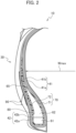
- FIG. 3 is a partially enlarged sectional view of the pneumatic tire 10.
- FIG. 3 as in FIG. 2 , in order to facilitate identification, only a part of the components is displayed with cross section hatching.
- the body portion 41 and the folded portion 42 of the carcass 40 are formed by a plurality of plies, specifically, two plies, but in at least a part of the region where the insert 80 is provided, the thickness of a side rubber 31 provided outside in the tire width direction of the carcass 40 is substantially the same as the ply thickness obtained by combining the body portion 41 and the folded portion 42 formed by a plurality of plies.
- the thickness D1 of the side rubber 31 is substantially the same as the thickness of the ply 41 a, the ply 41 b, the ply 42 a and the ply 42 b combined.
- the ply thicknesses of the ply 41 a, the ply 41 b, the ply 42 a, and the ply 42 b are each about 1 mm. Therefore, the thickness D1 is about 4 mm. By substantially the same it is meant that the thickness D1 is within ⁇ 10% of the total thickness of the plurality of plies.
- the thickness D1 is the thickness of the side rubber 31 at the maximum width position Wmax.
- the thickness D1 that is, the thickness of the side rubber 31 at the maximum width position Wmax, is not less than 40% of the cross-sectional width (D1 + D1 ' in the figure) of tire side portion 30 at the maximum width position Wmax.
- the section width is the total thickness of tire side portion 30 along a straight line perpendicular to the outer surface of the tire width direction in tire sectional view as shown in FIG. 3 .
- the thickness of the side rubber 31 at the maximum width position Wmax is substantially the same as the thickness of the four plies (ply 41 a, ply 41 b, ply 42 a, and ply 42 b) forming the carcass 40.
- the thickness D2 of the side rubber 31 at the position of the rim line 90 is also substantially the same as the ply thickness obtained by combining the ply 41 a, the ply 41 b, the ply 42 a, and the ply 42 b.
- the thickness D2 is not less than 30% of the cross-sectional width (D2 + D2 ' in the figure) of the bead portion 60 at the position of the rim line 90.
- the section width is the total thickness of the bead portion 60 along a straight line perpendicular to the outer surface of the tire width direction in tire sectional view as shown in FIG. 3 .
- a plurality of rim lines 90 may be provided, and in such a case, the rim line 90 provided on the outermost side of the tire radial direction is used as a reference.
- the thickness D2 does not include a portion of the rim line 90 protruding from the outer surface of the bead portion 60 in the tire width direction.
- the thickness D1 and the thickness D2 do not include the thickness of the second bead filler 65. That is, the thickness D1 (thickness D2) is a distance from the tire width direction outer surface of the second bead filler 65 to the tire width direction outer surface of the folded portion 42 (ply 42 a) of the carcass 40.
- the positions of the thickness D1 and the thickness D2 in the tire radial direction are provided with the flipper 70 (outer portion 72) and the insert 80.
- an outer end 72 a of an outer portion 72 of the flipper 70 in the tire radial direction is positioned outside of the tire radial direction than an outer end 71 a of an inner portion 71 of the flipper 70 in the tire radial direction.
- the outer end 72 a is located outside of the 50% of the section height SH of the pneumatic tire 10 in the tire radial direction.
- the section height SH is the height of the pneumatic tire 10 from the inside edge of the bead portion 60 in the tire radial direction to the outside edge of the tread portion 20 in the tire radial direction that is not rim assembled.
- the outer end 72 a is provided at 54% of the section height SH.
- the position of 54% of the section height SH is based on the inner edge of the bead portion 60 in the tire radial direction (hereinafter the same).
- the outer end 71 a in the tire radial direction of the inner portion 71 of the flipper 70 is provided at 20% of the section height SH.
- An outer end 80 a of the insert 80 in the tire radial direction is positioned inside in the tire radial direction than at 50% of the section height SH.
- the outer end 80 a is provided at 46% of the section height SH.
- An outer end 65 a of the second bead filler 65 in the tire radial direction is close to the maximum width position Wmax but is positioned inside in the tire radial direction than the maximum width position Wmax.
- the flipper 70 (first reinforcing member) is provided in the bead portion 60 of the pneumatic tire 10, and the insert 80 (second reinforcing member) is provided between the bead filler 62 and the outer portion 72 of the flipper 70.
- the thickness D1 of the side rubber 31 is substantially the same as the ply thickness obtained by combining the body portion 41 and the folded portion 42 of the carcass 40 formed by the plurality of plies.
- the thickness of the side rubber 31 is thicker than a conventional pneumatic tire of the same kind. Specifically, the thickness (thickness D1 and thickness D2) of the rubber is increased from the maximum width position Wmax to the rim line 90. That is, the thickness of the side rubber 31 is increased in at least a part where the flipper 70 and the insert 80 are provided in the tire radial direction.
- the longitudinal spring property and the damping property of the pneumatic tire 10 can be improved without increasing the case rigidity.
- the thicker gauging of the side rubber 31 improves the longitudinal spring property, and this promotes the shearing deformation of the tire side portion 30 which is relatively more easily deformed than the tread portion 20. Since the shape of the carcass 40 (cross-sectional shape along the tire width direction and the tire radial direction) is hard to deform, the axial force of pneumatic tire 10 during cornering can be improved.
- the damping property of tire (flexibility of tire (carcass 40) in the tire radial direction) during cornering can be optimized by making the thickness gauge of the side rubber 31, the attitude of the vehicle during cornering can be easily maintained.
- the improvement of the axial force during cornering and the ease of maintaining the attitude of the vehicle can be made compatible at a high level.
- a high degree of compatibility between the improvement of axial force during cornering and the ease of maintaining the attitude of the vehicle can contribute to the improvement of the controllability in critical condition of tire performance (gripping force, etc.) during cornering.
- the case rigidity means rigidity of the carcass 40 itself forming tire skeleton (case).
- the thickness of the side rubber 31 at the maximum width position Wmax is 40% or more of the cross-sectional width of the tire side portion 30 at the maximum width position Wmax.
- the thickness D2 of the side rubber 31 at the position of the rim line 90 is 30% or more of the sectional width of the bead portion 60 at the position of the rim line 90. Therefore, the relative thickness of the side rubber 31 is increased from the tire side portion 30 to the bead portion 60.
- the longitudinal spring property and the damping property of the pneumatic tire 10 can be improved more appropriately, and the improvement of the axial force during cornering and the ease of maintaining the attitude of the vehicle can be made compatible in a higher dimension.
- the thickness of the side rubber 31 at the maximum width position Wmax is substantially the same as the thickness of the four plies (ply 41 a, ply 41 b, ply 42 a, and ply 42 b) forming the carcass 40. Therefore, the longitudinal spring property and the damping property of the pneumatic tire 10 can be more appropriately improved while securing a balance with the case rigidity of the carcass 40. Thus, the improvement of the axial force during cornering and the ease of maintaining the attitude of the vehicle can be made compatible in a higher dimension.
- the outer end 72 a of the outer portion 72 of the flipper 70 in the tire radial direction is positioned outside in the tire radial direction than the outer end 71 a in the tire radial direction of the inner portion 71 of the 70 flipper.
- the outer end 80 a of the insert 80 in the tire radial direction is positioned inside in the tire radial direction than at 50% of the section height SH. Further, the outer end 65 a of the second bead filler 65 in the tire radial direction is close to the maximum width position Wmax but is located inside in the tire radial direction than the maximum width position Wmax.
- the second bead filler 65 is provided in the above-described embodiment, the second bead filler 65 may not necessarily be provided.
- the thickness D1 (thickness D2) of the side rubber 31 is a distance from the tire width direction outer surface of the tire side portion 30 (bead portion 60) to the tire width direction outer surface of the folded portion 42 (ply 42 a) of the carcass 40.
- the outer end 80 a of the insert 80 in the tire radial direction is positioned inside in the tire radial direction than at 50% of the section height SH, and the outer end 65 a in the tire radial direction of the second bead filler 65 is positioned inside the maximum width position Wmax while approaching the maximum width position Wmax, but such a positional relationship is not required.
- the outer end 72 a of the outer portion 72 of the flipper 70 in the tire radial direction is positioned outside in the tire radial direction than the outer end 71 a of the inner portion 71 of the flipper 70 in the tire radial direction, but such a positional relationship is not required.
Landscapes
- Engineering & Computer Science (AREA)
- Mechanical Engineering (AREA)
- Tires In General (AREA)
Description
- The present invention relates to a tire having high cornering performance.
- Conventionally, in pneumatic tire (below referred to as tire) mounted on a four-wheel vehicle, for the purpose of improving cornering performance, a structure in which a side reinforcing layer composed of a cloth rubberized with a plurality of cords is provided on tire side portion is known (refer to Patent Literature 1).
- Such a side reinforcing layer is provided from an outer tire width direction end of belt layer provided inside the of tread portion of tire radial direction to an outer end of tire radial direction of bead portion. Thus, since the rigidity of tire side portion is improved, the gripping force and responsiveness during cornering of the vehicle can be improved.
-
JP5841383B2 -
JP6194151B2 -
US2017197471A1 discloses a pneumatic tire includes a buttress reinforcing layer. A carcass includes a first ply and a second ply. The first ply and the second ply each have a main portion that is extended on and between beads on both sides. The buttress reinforcing layer extends along the first ply and the second ply between the first ply and the second ply. An outer end of the buttress reinforcing layer is disposed inward of a shoulder region of a tread in a radial direction. An inner end of the buttress reinforcing layer is disposed at a maximum width position of the tire or disposed outward of the maximum width position of the tire in the radial direction. -
JP5809909B - [Patent Literature 1]
Japanese Unexamined Patent Application Publication No. 2010-274799 - However, with the performance improvement of the vehicle, further improvement of cornering performance, in particular, improvement of controllability in the critical condition of tire performance (gripping force, etc.) during cornering (below, referred to as controllability in critical condition) is required.
- In general, by improving the axial force in the small steering angle region at the start of cornering and optimizing the shear deformation of tread portion in the large steering angle region after entering the corner, performance such as gripping force and responsiveness can be expected to be improved.
- In addition, in order to improve the controllability in critical condition, it is essential to effectively function the ground contact surface of tread portion. In particular, in order to improve the axial force, it is important to promote the shear deformation of tread portion. As a method for promoting the shear deformation of tread portion, the case rigidity of tire can be increased.
- However, when the case rigidity of tire is increased, the damping property of tire (flexibility of tire of tire radial direction) during cornering decreases, so that it becomes difficult to maintain the attitude of the vehicle in the state where the load is applied to tire during cornering. Therefore, the time dependency of the lateral force (Fy) is reduced.
- Accordingly, an object of the present invention is to provide a tire in which the improvement of the axial force and the ease of maintaining the attitude of the vehicle during cornering can be achieved at a high level.
- According to a first aspect of the invention there is provided a tire (pneumatic tire 10) including a tread portion (tread portion 20) in contacting with a road surface, a tire side portion (tire side portion 30) continuous to the tread portion and positioned inside in a tire radial direction of the tread portion, a bead portion (bead portion 60) continuous to the tire side portion and positioned inside in the tire radial direction of the tire side portion, and a carcass (carcass 40) that forms tire skeleton. The bead portion includes a bead core (bead core 61) and a bead filler (bead filler 62) provided outside in the tire radial direction of the bead core, the carcass includes a body portion (body portion 41) and a folded portion (folded portion 42) continuous to the body portion and folded back to outside in a tire width direction via the bead core, and a part of the body portion and the folded portion are formed by at least a plurality of plies (
ply 41 a,ply 41 b,ply 42 a,ply 42 b). The carcass include a first reinforcing member (flipper 70) folded back from an inner side in the tire width direction via the bead core to an outer side in the tire width direction to cover the bead core and the bead filler, and a second reinforcing member (insert 80) provided between the bead filler and the first reinforcing member folded outside in the tire width direction. In at least a part of the region where the second reinforcing member is provided, thickness (thickness D1, thickness D2) of a side rubber (side rubber 30) provided on the outside in the tire width direction of the carcass is substantially the same as ply thickness combining the body portion and the folded portion formed by a plurality of plies. A thickness (D1, D2) of the side rubber (31) at a maximum width position of tire is 40% or more of a sectional width of the tire side portion (30) at the maximum width position -
-
FIG. 1 is a cross-sectional view of apneumatic tire 10. -
FIG 2 is a partial cross-sectional view of thepneumatic tire 10. -
FIG. 3 is a partially enlarged sectional view of thepneumatic tire 10. - Embodiments will be described below with reference to the drawings. The same functions and configurations are denoted by the same or similar reference numerals, and description thereof will be omitted as appropriate.
-
FIG. 1 is a sectional view of thepneumatic tire 10 according to the present embodiment. Specifically,FIG. 1 is a cross-sectional view of thepneumatic tire 10 taken along tire width direction and tire radial direction. InFIG. 1 , sectional hatching is not shown. - As shown in
FIG. 1 , thepneumatic tire 10 includes atread portion 20, atire side portion 30, acarcass 40, abelt layer 50, and abead portion 60. - In the present embodiment, the
pneumatic tire 10 is a four-wheel vehicle, specifically, a tire assumed to be mounted on a passenger vehicle. In particular, thepneumatic tire 10 can be suitably used for a four-wheel vehicle such as a sports type vehicle emphasizing cornering performance. - The
tread portion 20 is a portion in contact with a road surface. On thetread portion 20, a pattern (not shown) is formed according to the use environment of thepneumatic tire 10 and the type of vehicle to be mounted. - The
tire side portion 30 is continuous to thetread portion 20 and is positioned inside in the tire radial direction of thetread portion 20. Thetire side portion 30 is an area from the outer edge of the tire width direction of thetread portion 20 to the upper edge of thebead portion 60. Thetire side portion 30 is sometimes referred to as a sidewall. - The
carcass 40 forms the skeleton (tire skeleton) of thepneumatic tire 10 . In this embodiment, thecarcass 40 has a radial structure in which carcass cords (not shown) disposed radially along the tire radial direction are coated with a rubber material. Thecarcass 40 has abody portion 41 and a foldedportion 42. - The
body portion 41 extends over thetread portion 20, thetire side portion 30 and thebead portion 60 and thebody portion 41 is a portion until it is folded back at thebead portion 60. - The folded
portion 42 is a portion continuous to thebody portion 41 and folded back to outside in the tire width direction via abead core 61. Theouter end 42 e of the foldedportion 42 in the tire radial direction extends to the inside in the tire radial direction of thebelt layer 50. That is, thecarcass 40 has an envelope structure. - However, the
carcass 40 may not necessarily have an envelope structure, and for example, it may also have a high-turn-up structure in which theouter end 42 e does not reach thebelt layer 50 but is positioned inside in tire radial direction of thebelt layer 50, more specifically, in the vicinity of the maximum width position Wmax (not shown inFIG. 1 , seeFIG. 2 ). - The carcass cord is formed of an organic fiber such as nylon as in the case of a tire for standard four-wheel vehicles. In the present embodiment, the
carcass 40 is formed of a plurality of plies (carcass plies). The configuration of thecarcass 40 will be described later. - The
belt layer 50 is provided inside in the tire radial direction of thetread portion 20. In this embodiment, thebelt layer 50 includes a pair of crossing belts with crossed steel cords. Thebelt layer 50 may include a reinforcing belt provided at an end of the crossing belt in the tire width direction. - The
bead portion 60 is continuous to thetire side portion 30 and is positioned inside in the tire radial direction of thetire side portion 30. Thebead portion 60 is annular extending to the tire circumferential direction and is locked to a rim wheel (not shown). - The
bead portion 60 includes abead core 61 and abead filler 62. - The
bead core 61 is formed by twisting a plurality of metal cords. For example, thebead core 61 may be formed of steel cords. The number of cords (the number of cores) is not particularly limited, but in this embodiment, the number of cores is about 24. - The
bead filler 62 is provided outside in the tire radial direction of thebead core 61. Thebead filler 62 is formed by using rubber harder than other parts formed by rubber. Thebead filler 62 is provided to fill a space having wedge-shaped in cross-sectional shape formed by thebody portion 41 and the foldedportion 42 of thecarcass 40. - In this embodiment, a
second bead filler 65 is provided. Thesecond bead filler 65 is provided outside in the tire width direction of the foldedportion 42 of thecarcass 40. Thesecond bead filler 65 is also formed of the same member as thebead filler 62. - The
pneumatic tire 10 also includes aflipper 70 and aninsert 80. - The
flipper 70 is provided to cover the periphery of thebead portion 60. Specifically, theflipper 70 is folded back from the inside in the tire width direction via thebead core 61 to the outside in the tire width direction to cover thebead core 61 and thebead filler 62. - The
flipper 70 has a structure in which a plurality of cords arranged slantingly to the tire radial direction are covered with rubber. An organic fiber such as aramid fiber can be used as the cord. - The
flipper 70 reinforces thebead portion 60. In this embodiment, theflipper 70 constitutes the first reinforcing member. - The
insert 80 is provided outside in the tire width direction of thebead filler 62. Specifically, theinsert 80 is provided between thebead filler 62 and theflipper 70 folded outside in the tire width direction. - The
insert 80 is also formed by covering a plurality of cords arranged slantingly to the tire radial direction with rubber. The cord may be an organic fiber such as aramid fibers or a metal such as steel. - The
insert 80 reinforces thetire side portion 30 and thebead portion 60. In this embodiment, theinsert 80 constitutes the second reinforcing member. - The
flipper 70 and theinsert 80 may be referred to as a side reinforcing layer or the like. - A
rim line 90 is provided on an outer side surface of thebead portion 60 of tire width direction. Therim line 90 is a projection formed along thebead portion 60 to confirm that the tire circumferential direction is correctly mounted on the rim wheel. In this embodiment, therim line 90 is provided on the outer side in the tire radial direction about 6 mm from the outer end of a rim flange 110. -
FIG. 2 is a partial cross-sectional view of thepneumatic tire 10. InFIG. 2 , in order to facilitate identification, the cross section hatching is shown only for a part of the components. - As shown in
FIG. 2 , in this embodiment, thecarcass 40 is formed by a plurality of plies (carcass plies). Specifically, thebody portion 41 is formed by two plies. A part of the foldedportion 42 is formed by 2 plies. - More specifically, the
body portion 41 is formed by aply 41 a and aply 41 b. The foldedportion 42 is formed by aply 42 a and aply 42 b. Theply 42 b terminates near the center of thebead filler 62 in the tire radial direction. - The
flipper 70 has aninner portion 71 and anouter portion 72. Theinner portion 71 is a portion positioned inside thebead portion 60 in the tire width direction. Theouter portion 72 is a portion positioned outside thebead portion 60 in the tire width direction. - The
tire side portion 30 has the maximum width position Wmax at which tire width of thepneumatic tire 10, that is, the width along the tire width direction, becomes maximum. In the present embodiment, the maximum width position Wmax is a position where the width along the tire width direction inpneumatic tire 10 which is not rim-assembled is maximum . -
FIG. 3 is a partially enlarged sectional view of thepneumatic tire 10. InFIG. 3 , as inFIG. 2 , in order to facilitate identification, only a part of the components is displayed with cross section hatching. - As described above, the
body portion 41 and the foldedportion 42 of thecarcass 40 are formed by a plurality of plies, specifically, two plies, but in at least a part of the region where theinsert 80 is provided, the thickness of aside rubber 31 provided outside in the tire width direction of thecarcass 40 is substantially the same as the ply thickness obtained by combining thebody portion 41 and the foldedportion 42 formed by a plurality of plies. - Specifically, the thickness D1 of the
side rubber 31 is substantially the same as the thickness of theply 41 a, theply 41 b, theply 42 a and theply 42 b combined. In this embodiment, the ply thicknesses of theply 41 a, theply 41 b, theply 42 a, and theply 42 b are each about 1 mm. Therefore, the thickness D1 is about 4 mm. By substantially the same it is meant that the thickness D1 is within ± 10% of the total thickness of the plurality of plies. - The thickness D1 is the thickness of the
side rubber 31 at the maximum width position Wmax. The thickness D1, that is, the thickness of theside rubber 31 at the maximum width position Wmax, is not less than 40% of the cross-sectional width (D1 + D1 ' in the figure) oftire side portion 30 at the maximum width position Wmax. Note that the section width is the total thickness oftire side portion 30 along a straight line perpendicular to the outer surface of the tire width direction in tire sectional view as shown inFIG. 3 . - That is, in the present embodiment, the thickness of the
side rubber 31 at the maximum width position Wmax is substantially the same as the thickness of the four plies (ply 41 a, ply 41 b, ply 42 a, and ply 42 b) forming thecarcass 40. - In addition, the thickness D2 of the
side rubber 31 at the position of therim line 90 is also substantially the same as the ply thickness obtained by combining theply 41 a, theply 41 b, theply 42 a, and theply 42 b. The thickness D2 is not less than 30% of the cross-sectional width (D2 + D2 ' in the figure) of thebead portion 60 at the position of therim line 90. - Note that the section width is the total thickness of the
bead portion 60 along a straight line perpendicular to the outer surface of the tire width direction in tire sectional view as shown inFIG. 3 . As shown inFIG. 3 , a plurality ofrim lines 90 may be provided, and in such a case, therim line 90 provided on the outermost side of the tire radial direction is used as a reference. The thickness D2 does not include a portion of therim line 90 protruding from the outer surface of thebead portion 60 in the tire width direction. - In this embodiment, the thickness D1 and the thickness D2 do not include the thickness of the
second bead filler 65. That is, the thickness D1 (thickness D2) is a distance from the tire width direction outer surface of thesecond bead filler 65 to the tire width direction outer surface of the folded portion 42 (ply 42 a) of thecarcass 40. - The positions of the thickness D1 and the thickness D2 in the tire radial direction are provided with the flipper 70 (outer portion 72) and the
insert 80. - Also, an
outer end 72 a of anouter portion 72 of theflipper 70 in the tire radial direction is positioned outside of the tire radial direction than anouter end 71 a of aninner portion 71 of theflipper 70 in the tire radial direction. In addition, theouter end 72 a is located outside of the 50% of the section height SH of thepneumatic tire 10 in the tire radial direction. - The section height SH is the height of the
pneumatic tire 10 from the inside edge of thebead portion 60 in the tire radial direction to the outside edge of thetread portion 20 in the tire radial direction that is not rim assembled. In this embodiment, theouter end 72 a is provided at 54% of the section height SH. The position of 54% of the section height SH is based on the inner edge of thebead portion 60 in the tire radial direction (hereinafter the same). - The
outer end 71 a in the tire radial direction of theinner portion 71 of theflipper 70 is provided at 20% of the section height SH. - An
outer end 80 a of theinsert 80 in the tire radial direction is positioned inside in the tire radial direction than at 50% of the section height SH. In this embodiment, theouter end 80 a is provided at 46% of the section height SH. - An
outer end 65 a of thesecond bead filler 65 in the tire radial direction is close to the maximum width position Wmax but is positioned inside in the tire radial direction than the maximum width position Wmax. - According to the embodiment described above, the following effects can be obtained. Specifically, the flipper 70 (first reinforcing member) is provided in the
bead portion 60 of thepneumatic tire 10, and the insert 80 (second reinforcing member) is provided between thebead filler 62 and theouter portion 72 of theflipper 70. - In at least a part of the region where the
insert 80 is provided, the thickness D1 of theside rubber 31 is substantially the same as the ply thickness obtained by combining thebody portion 41 and the foldedportion 42 of thecarcass 40 formed by the plurality of plies. - The thickness of the
side rubber 31 is thicker than a conventional pneumatic tire of the same kind. Specifically, the thickness (thickness D1 and thickness D2) of the rubber is increased from the maximum width position Wmax to therim line 90. That is, the thickness of theside rubber 31 is increased in at least a part where theflipper 70 and theinsert 80 are provided in the tire radial direction. - By increasing the thickness of the side rubber 31 (thicker gauging) and arranging the
flipper 70 and theinsert 80, the longitudinal spring property and the damping property of thepneumatic tire 10 can be improved without increasing the case rigidity. - More specifically, the thicker gauging of the
side rubber 31 improves the longitudinal spring property, and this promotes the shearing deformation of thetire side portion 30 which is relatively more easily deformed than thetread portion 20. Since the shape of the carcass 40 (cross-sectional shape along the tire width direction and the tire radial direction) is hard to deform, the axial force ofpneumatic tire 10 during cornering can be improved. - Further, since the damping property of tire (flexibility of tire (carcass 40) in the tire radial direction) during cornering can be optimized by making the thickness gauge of the
side rubber 31, the attitude of the vehicle during cornering can be easily maintained. - That is, according to the
pneumatic tire 10, the improvement of the axial force during cornering and the ease of maintaining the attitude of the vehicle can be made compatible at a high level. In addition, a high degree of compatibility between the improvement of axial force during cornering and the ease of maintaining the attitude of the vehicle can contribute to the improvement of the controllability in critical condition of tire performance (gripping force, etc.) during cornering. - The case rigidity means rigidity of the
carcass 40 itself forming tire skeleton (case). - The thickness of the
side rubber 31 at the maximum width position Wmax is 40% or more of the cross-sectional width of thetire side portion 30 at the maximum width position Wmax. The thickness D2 of theside rubber 31 at the position of therim line 90 is 30% or more of the sectional width of thebead portion 60 at the position of therim line 90. Therefore, the relative thickness of theside rubber 31 is increased from thetire side portion 30 to thebead portion 60. Thus, the longitudinal spring property and the damping property of thepneumatic tire 10 can be improved more appropriately, and the improvement of the axial force during cornering and the ease of maintaining the attitude of the vehicle can be made compatible in a higher dimension. - In the present embodiment, the thickness of the
side rubber 31 at the maximum width position Wmax is substantially the same as the thickness of the four plies (ply 41 a, ply 41 b, ply 42 a, and ply 42 b) forming thecarcass 40. Therefore, the longitudinal spring property and the damping property of thepneumatic tire 10 can be more appropriately improved while securing a balance with the case rigidity of thecarcass 40. Thus, the improvement of the axial force during cornering and the ease of maintaining the attitude of the vehicle can be made compatible in a higher dimension. - In this embodiment, the
outer end 72 a of theouter portion 72 of theflipper 70 in the tire radial direction is positioned outside in the tire radial direction than theouter end 71 a in the tire radial direction of theinner portion 71 of the 70 flipper. - Also, the
outer end 80 a of theinsert 80 in the tire radial direction is positioned inside in the tire radial direction than at 50% of the section height SH. Further, theouter end 65 a of thesecond bead filler 65 in the tire radial direction is close to the maximum width position Wmax but is located inside in the tire radial direction than the maximum width position Wmax. - Thus, over a wide range of the
tire side portion 30 in the tire radial direction, characteristics may be imparted to thetire side portion 30 that contribute to appropriate improvements in longitudinal spring property and damping property of thepneumatic tire 10. Thus, the improvement of the axial force during cornering and the ease of maintaining the attitude of the vehicle can be made compatible in a higher dimension. - Although the contents of the present invention have been described above with reference to the examples, it will be obvious to those skilled in the art that the present invention is not limited to these descriptions and that various modifications and improvements are possible as claimed.
- For example, although the
second bead filler 65 is provided in the above-described embodiment, thesecond bead filler 65 may not necessarily be provided. In this case, the thickness D1 (thickness D2) of theside rubber 31 is a distance from the tire width direction outer surface of the tire side portion 30 (bead portion 60) to the tire width direction outer surface of the folded portion 42 (ply 42 a) of thecarcass 40. - In the embodiment described above, the
outer end 80 a of theinsert 80 in the tire radial direction is positioned inside in the tire radial direction than at 50% of the section height SH, and theouter end 65 a in the tire radial direction of thesecond bead filler 65 is positioned inside the maximum width position Wmax while approaching the maximum width position Wmax, but such a positional relationship is not required. - In the embodiment described above, the
outer end 72 a of theouter portion 72 of theflipper 70 in the tire radial direction is positioned outside in the tire radial direction than theouter end 71 a of theinner portion 71 of theflipper 70 in the tire radial direction, but such a positional relationship is not required. -
- 10 Pneumatic tire
- 20 Tread portion
- 30 Tire side portion
- 31 Side rubber
- 40 Carcass
- 41 Body portion
- 41 a Ply
- 41 b Ply
- 42 Folded portion
- 42 a Ply
- 42 b Ply
- 42 e Outer end
- 50 Belt layer
- 60 Bead portion
- 61 Bead core
- 62 Bead filler
- 65 Second bead filler
- 65 a Outer end
- 70 Flipper
- 71 Inner portion
- 71 a Outer end
- 72 Outer portion
- 72 a Outer end
- 80 Insert
- 80 a Outer end
- 90 Rim line
Claims (5)
- A tire (10) comprising:a tread portion (20) for contacting with a road surface;a tire side portion (30) continuous to the tread portion (20) and positioned inside in a tire radial direction of the tread portion (20);a bead portion (60) continuous to the tire side portion (30) and positioned inside in the tire radial direction of the tire side portion (30); anda carcass (40) that forms a tire skeleton, whereinthe bead portion (60) includes a bead core (61) and a bead filler (62) provided outside in the tire radial direction of the bead core (61);the carcass (40) includes a body portion (41) and a folded portion (42) continuous to the body portion (41) and folded back to outside in a tire width direction via the bead core (61), anda part of the body portion (41) and the folded portion (42) are formed by at least a plurality of plies (41a, 41b, 42a, 42b), whereinthe carcass comprises:a first reinforcing member (70) folded back from an inner side in the tire width direction via the bead core (61) to an outer side in the tire width direction to cover the bead core (61) and the bead filler (62); anda second reinforcing member (80) provided between the bead filler (62) and the first reinforcing member (70) folded outside in the tire width direction, whereinin at least a part of the region where the second reinforcing member (80) is provided, a thickness of a side rubber (31) provided on the outside in the tire width direction of the carcass (40) is substantially the same as a ply thickness combining the body portion (41) and the folded portion (42) formed by the plurality of plies (41a, 42b, 42a, 42b);wherein a thickness (D1, D2) of the side rubber (31) at a maximum width position of tire is 40% or more of a sectional width of the tire side portion (30) at the maximum width position.
- The tire according to claim 1, wherein a thickness of the side rubber (31) at a position of a rim line (90) of the tire (10) is 30% or more of a sectional width of the bead portion (60) at the position of the rim line (90).
- The tire according to claims 1 or 2, wherein the thickness (D1, D2) of the side rubber (31) at the maximum width position of the tire (10) is substantially the same as thickness of four sheets of the ply.
- The tire (10) according to any one of claims 1 to 3, wherein
the first reinforcing member (70) includes:an inner portion (71) positioned inside in the tire width direction of the bead portion; andan outer portion (72) positioned outside in the tire width direction of the bead portion (60), whereinan outer end (72a) in the tire radial direction of the outer portion (72) is positioned outside of the inner portion (71) in the tire radial direction and is positioned outside in the tire radial direction of a position of a 50% of section height. - The tire (10) according to claim 4, wherein an outer end (80a) in the tire radial direction of the second reinforcement member (80) is positioned inside in the tire radial direction of the 50% of the section height.
Applications Claiming Priority (2)
| Application Number | Priority Date | Filing Date | Title |
|---|---|---|---|
| JP2019091240A JP7117267B2 (en) | 2019-05-14 | 2019-05-14 | tire |
| PCT/JP2020/018530 WO2020230688A1 (en) | 2019-05-14 | 2020-05-07 | Tire |
Publications (3)
| Publication Number | Publication Date |
|---|---|
| EP3970997A1 EP3970997A1 (en) | 2022-03-23 |
| EP3970997A4 EP3970997A4 (en) | 2023-01-18 |
| EP3970997B1 true EP3970997B1 (en) | 2025-01-01 |
Family
ID=73223232
Family Applications (1)
| Application Number | Title | Priority Date | Filing Date |
|---|---|---|---|
| EP20806641.5A Active EP3970997B1 (en) | 2019-05-14 | 2020-05-07 | Tire |
Country Status (5)
| Country | Link |
|---|---|
| US (1) | US20220258545A1 (en) |
| EP (1) | EP3970997B1 (en) |
| JP (1) | JP7117267B2 (en) |
| CN (1) | CN113825653B (en) |
| WO (1) | WO2020230688A1 (en) |
Families Citing this family (4)
| Publication number | Priority date | Publication date | Assignee | Title |
|---|---|---|---|---|
| JP2022106214A (en) * | 2021-01-06 | 2022-07-19 | 住友ゴム工業株式会社 | Pneumatic tire and manufacturing method of the same |
| JP7836167B2 (en) * | 2021-11-05 | 2026-03-26 | Toyo Tire株式会社 | pneumatic tires |
| CN114312164B (en) * | 2022-01-27 | 2024-04-05 | 青岛双星轮胎工业有限公司 | Reinforcement layer and explosion-proof tire |
| CN114919341B (en) * | 2022-05-26 | 2026-01-16 | 山东玲珑轮胎股份有限公司 | Engineering machinery radial tire reinforced tire bead |
Family Cites Families (29)
| Publication number | Priority date | Publication date | Assignee | Title |
|---|---|---|---|---|
| IT1042802B (en) * | 1975-09-24 | 1980-01-30 | Pirelli | IMPROVEMENT AT RADIAL TIRES PROVIDED WITH STRUCTURE OF TAPPIGIO IMENTO IN EIANCHI |
| JPH0811233A (en) * | 1994-06-29 | 1996-01-16 | Bridgestone Corp | Pneumatic flat radial tire |
| JP2962658B2 (en) * | 1994-08-22 | 1999-10-12 | 住友ゴム工業株式会社 | Pneumatic tubeless tire |
| JPH08164718A (en) * | 1994-12-13 | 1996-06-25 | Ohtsu Tire & Rubber Co Ltd :The | Pneumatic radial tire |
| JP4450449B2 (en) * | 1999-04-23 | 2010-04-14 | 株式会社ブリヂストン | Pneumatic radial tire |
| JP4493353B2 (en) * | 2004-01-23 | 2010-06-30 | 株式会社ブリヂストン | Run flat tire |
| JP2006137252A (en) * | 2004-11-10 | 2006-06-01 | Bridgestone Corp | High performance low-profile tire for passenger four-wheeled car and installation method of tire |
| DE102006011158A1 (en) * | 2006-03-10 | 2007-09-13 | Continental Aktiengesellschaft | Vehicle tires |
| JP5030525B2 (en) * | 2006-10-12 | 2012-09-19 | 株式会社ブリヂストン | Pneumatic radial tire |
| WO2008074337A1 (en) * | 2006-12-18 | 2008-06-26 | Pirelli Tyre S.P.A. | Tire having an improved bead structure |
| ATE517769T1 (en) * | 2007-10-03 | 2011-08-15 | Pirelli | TIRES WITH AN IMPROVED BEAD STRUCTURE |
| JP4685918B2 (en) * | 2008-12-08 | 2011-05-18 | 住友ゴム工業株式会社 | Pneumatic tire |
| JP2010274799A (en) | 2009-05-28 | 2010-12-09 | Bridgestone Corp | Pneumatic tire |
| EP2602124B1 (en) * | 2010-08-06 | 2019-03-13 | Bridgestone Corporation | Tire |
| JP5711979B2 (en) * | 2011-01-17 | 2015-05-07 | 株式会社ブリヂストン | tire |
| JP6194151B2 (en) * | 2011-01-19 | 2017-09-06 | 株式会社ブリヂストン | Pneumatic tire |
| JP5860625B2 (en) * | 2011-07-26 | 2016-02-16 | 株式会社ブリヂストン | tire |
| JP5841383B2 (en) * | 2011-09-20 | 2016-01-13 | 住友ゴム工業株式会社 | Pneumatic tire |
| JP5809909B2 (en) * | 2011-09-29 | 2015-11-11 | 東洋ゴム工業株式会社 | Pneumatic tire |
| JP2013086771A (en) * | 2011-10-21 | 2013-05-13 | Yokohama Rubber Co Ltd:The | Pneumatic tire |
| JP2013169825A (en) * | 2012-02-17 | 2013-09-02 | Bridgestone Corp | Pneumatic tire |
| JP6398723B2 (en) * | 2012-11-30 | 2018-10-03 | 横浜ゴム株式会社 | Pneumatic tire |
| JP6013908B2 (en) * | 2012-12-28 | 2016-10-25 | 住友ゴム工業株式会社 | Heavy duty tire |
| WO2015008752A1 (en) * | 2013-07-17 | 2015-01-22 | 株式会社ブリヂストン | Tire |
| JP2016107725A (en) * | 2014-12-03 | 2016-06-20 | 横浜ゴム株式会社 | Pneumatic tire |
| JP6720537B2 (en) * | 2016-01-08 | 2020-07-08 | 住友ゴム工業株式会社 | Pneumatic tire |
| CN106114075A (en) * | 2016-08-30 | 2016-11-16 | 山东玲珑轮胎股份有限公司 | Radial tire bead |
| JP2018069901A (en) * | 2016-10-28 | 2018-05-10 | 住友ゴム工業株式会社 | Pneumatic tire |
| JP2018099850A (en) * | 2016-12-21 | 2018-06-28 | 東洋ゴム工業株式会社 | Pneumatic tire manufacturing method |
-
2019
- 2019-05-14 JP JP2019091240A patent/JP7117267B2/en active Active
-
2020
- 2020-05-07 EP EP20806641.5A patent/EP3970997B1/en active Active
- 2020-05-07 CN CN202080035831.6A patent/CN113825653B/en active Active
- 2020-05-07 US US17/595,246 patent/US20220258545A1/en not_active Abandoned
- 2020-05-07 WO PCT/JP2020/018530 patent/WO2020230688A1/en not_active Ceased
Also Published As
| Publication number | Publication date |
|---|---|
| US20220258545A1 (en) | 2022-08-18 |
| CN113825653A (en) | 2021-12-21 |
| JP2020185871A (en) | 2020-11-19 |
| JP7117267B2 (en) | 2022-08-12 |
| EP3970997A4 (en) | 2023-01-18 |
| CN113825653B (en) | 2023-04-21 |
| EP3970997A1 (en) | 2022-03-23 |
| WO2020230688A1 (en) | 2020-11-19 |
Similar Documents
| Publication | Publication Date | Title |
|---|---|---|
| EP3970997B1 (en) | Tire | |
| JP4464700B2 (en) | Pneumatic tire and manufacturing method thereof | |
| JP4170821B2 (en) | Pneumatic radial tire | |
| JP4621091B2 (en) | Pneumatic tire | |
| JP4648561B2 (en) | Run flat tire | |
| CN102574431A (en) | Air-filled radial tire | |
| CN106274300B (en) | Heavy duty tires | |
| CN108367635B (en) | Pneumatic tires | |
| EP3594019B1 (en) | Heavy duty pneumatic tire | |
| JP6816543B2 (en) | Pneumatic tires | |
| EP3798027B1 (en) | Tire with improved bead portion | |
| JPH10193924A (en) | Pneumatic tire | |
| US7165590B2 (en) | Heavy duty pneumatic radial tire with carcass ply winding-up portion | |
| JP7172215B2 (en) | Heavy duty pneumatic tire | |
| US10005323B2 (en) | Reinforced bias- or radial-carcass tire | |
| JP2008174167A (en) | Pneumatic tire | |
| JP2005280456A (en) | Pneumatic tire | |
| US20220314705A1 (en) | Run-flat tire | |
| EP3904116A1 (en) | Run-flat tire | |
| JP4383158B2 (en) | Pneumatic tire | |
| JP2004306742A (en) | Pneumatic tire | |
| EP3885158A1 (en) | Run-flat tire | |
| JP7807910B2 (en) | pneumatic tires | |
| EP4403380B1 (en) | Tire | |
| JP7836167B2 (en) | pneumatic tires |
Legal Events
| Date | Code | Title | Description |
|---|---|---|---|
| STAA | Information on the status of an ep patent application or granted ep patent |
Free format text: STATUS: THE INTERNATIONAL PUBLICATION HAS BEEN MADE |
|
| PUAI | Public reference made under article 153(3) epc to a published international application that has entered the european phase |
Free format text: ORIGINAL CODE: 0009012 |
|
| STAA | Information on the status of an ep patent application or granted ep patent |
Free format text: STATUS: REQUEST FOR EXAMINATION WAS MADE |
|
| 17P | Request for examination filed |
Effective date: 20211112 |
|
| AK | Designated contracting states |
Kind code of ref document: A1 Designated state(s): AL AT BE BG CH CY CZ DE DK EE ES FI FR GB GR HR HU IE IS IT LI LT LU LV MC MK MT NL NO PL PT RO RS SE SI SK SM TR |
|
| DAV | Request for validation of the european patent (deleted) | ||
| DAX | Request for extension of the european patent (deleted) | ||
| A4 | Supplementary search report drawn up and despatched |
Effective date: 20221216 |
|
| RIC1 | Information provided on ipc code assigned before grant |
Ipc: B60C 9/02 20060101ALI20221212BHEP Ipc: B60C 15/06 20060101ALI20221212BHEP Ipc: B60C 9/08 20060101ALI20221212BHEP Ipc: B60C 13/00 20060101AFI20221212BHEP |
|
| GRAP | Despatch of communication of intention to grant a patent |
Free format text: ORIGINAL CODE: EPIDOSNIGR1 |
|
| STAA | Information on the status of an ep patent application or granted ep patent |
Free format text: STATUS: GRANT OF PATENT IS INTENDED |
|
| INTG | Intention to grant announced |
Effective date: 20240826 |
|
| P01 | Opt-out of the competence of the unified patent court (upc) registered |
Free format text: CASE NUMBER: APP_49453/2024 Effective date: 20240830 |
|
| GRAS | Grant fee paid |
Free format text: ORIGINAL CODE: EPIDOSNIGR3 |
|
| GRAA | (expected) grant |
Free format text: ORIGINAL CODE: 0009210 |
|
| STAA | Information on the status of an ep patent application or granted ep patent |
Free format text: STATUS: THE PATENT HAS BEEN GRANTED |
|
| AK | Designated contracting states |
Kind code of ref document: B1 Designated state(s): AL AT BE BG CH CY CZ DE DK EE ES FI FR GB GR HR HU IE IS IT LI LT LU LV MC MK MT NL NO PL PT RO RS SE SI SK SM TR |
|
| REG | Reference to a national code |
Ref country code: GB Ref legal event code: FG4D |
|
| REG | Reference to a national code |
Ref country code: CH Ref legal event code: EP |
|
| REG | Reference to a national code |
Ref country code: DE Ref legal event code: R096 Ref document number: 602020044149 Country of ref document: DE |
|
| REG | Reference to a national code |
Ref country code: IE Ref legal event code: FG4D |
|
| REG | Reference to a national code |
Ref country code: LT Ref legal event code: MG9D |
|
| REG | Reference to a national code |
Ref country code: NL Ref legal event code: MP Effective date: 20250101 |
|
| REG | Reference to a national code |
Ref country code: AT Ref legal event code: MK05 Ref document number: 1755889 Country of ref document: AT Kind code of ref document: T Effective date: 20250101 |
|
| PG25 | Lapsed in a contracting state [announced via postgrant information from national office to epo] |
Ref country code: NL Free format text: LAPSE BECAUSE OF FAILURE TO SUBMIT A TRANSLATION OF THE DESCRIPTION OR TO PAY THE FEE WITHIN THE PRESCRIBED TIME-LIMIT Effective date: 20250101 |
|
| PG25 | Lapsed in a contracting state [announced via postgrant information from national office to epo] |
Ref country code: FI Free format text: LAPSE BECAUSE OF FAILURE TO SUBMIT A TRANSLATION OF THE DESCRIPTION OR TO PAY THE FEE WITHIN THE PRESCRIBED TIME-LIMIT Effective date: 20250101 |
|
| PG25 | Lapsed in a contracting state [announced via postgrant information from national office to epo] |
Ref country code: PL Free format text: LAPSE BECAUSE OF FAILURE TO SUBMIT A TRANSLATION OF THE DESCRIPTION OR TO PAY THE FEE WITHIN THE PRESCRIBED TIME-LIMIT Effective date: 20250101 |
|
| PGFP | Annual fee paid to national office [announced via postgrant information from national office to epo] |
Ref country code: DE Payment date: 20250521 Year of fee payment: 6 |
|
| PG25 | Lapsed in a contracting state [announced via postgrant information from national office to epo] |
Ref country code: ES Free format text: LAPSE BECAUSE OF FAILURE TO SUBMIT A TRANSLATION OF THE DESCRIPTION OR TO PAY THE FEE WITHIN THE PRESCRIBED TIME-LIMIT Effective date: 20250101 |
|
| PG25 | Lapsed in a contracting state [announced via postgrant information from national office to epo] |
Ref country code: IS Free format text: LAPSE BECAUSE OF FAILURE TO SUBMIT A TRANSLATION OF THE DESCRIPTION OR TO PAY THE FEE WITHIN THE PRESCRIBED TIME-LIMIT Effective date: 20250501 Ref country code: NO Free format text: LAPSE BECAUSE OF FAILURE TO SUBMIT A TRANSLATION OF THE DESCRIPTION OR TO PAY THE FEE WITHIN THE PRESCRIBED TIME-LIMIT Effective date: 20250401 |
|
| PG25 | Lapsed in a contracting state [announced via postgrant information from national office to epo] |
Ref country code: HR Free format text: LAPSE BECAUSE OF FAILURE TO SUBMIT A TRANSLATION OF THE DESCRIPTION OR TO PAY THE FEE WITHIN THE PRESCRIBED TIME-LIMIT Effective date: 20250101 |
|
| PG25 | Lapsed in a contracting state [announced via postgrant information from national office to epo] |
Ref country code: PT Free format text: LAPSE BECAUSE OF FAILURE TO SUBMIT A TRANSLATION OF THE DESCRIPTION OR TO PAY THE FEE WITHIN THE PRESCRIBED TIME-LIMIT Effective date: 20250502 Ref country code: LV Free format text: LAPSE BECAUSE OF FAILURE TO SUBMIT A TRANSLATION OF THE DESCRIPTION OR TO PAY THE FEE WITHIN THE PRESCRIBED TIME-LIMIT Effective date: 20250101 |
|
| PGFP | Annual fee paid to national office [announced via postgrant information from national office to epo] |
Ref country code: FR Payment date: 20250528 Year of fee payment: 6 |
|
| PG25 | Lapsed in a contracting state [announced via postgrant information from national office to epo] |
Ref country code: GR Free format text: LAPSE BECAUSE OF FAILURE TO SUBMIT A TRANSLATION OF THE DESCRIPTION OR TO PAY THE FEE WITHIN THE PRESCRIBED TIME-LIMIT Effective date: 20250402 Ref country code: BG Free format text: LAPSE BECAUSE OF FAILURE TO SUBMIT A TRANSLATION OF THE DESCRIPTION OR TO PAY THE FEE WITHIN THE PRESCRIBED TIME-LIMIT Effective date: 20250101 |
|
| PG25 | Lapsed in a contracting state [announced via postgrant information from national office to epo] |
Ref country code: AT Free format text: LAPSE BECAUSE OF FAILURE TO SUBMIT A TRANSLATION OF THE DESCRIPTION OR TO PAY THE FEE WITHIN THE PRESCRIBED TIME-LIMIT Effective date: 20250101 |
|
| PG25 | Lapsed in a contracting state [announced via postgrant information from national office to epo] |
Ref country code: CZ Free format text: LAPSE BECAUSE OF FAILURE TO SUBMIT A TRANSLATION OF THE DESCRIPTION OR TO PAY THE FEE WITHIN THE PRESCRIBED TIME-LIMIT Effective date: 20250101 |
|
| PG25 | Lapsed in a contracting state [announced via postgrant information from national office to epo] |
Ref country code: SE Free format text: LAPSE BECAUSE OF FAILURE TO SUBMIT A TRANSLATION OF THE DESCRIPTION OR TO PAY THE FEE WITHIN THE PRESCRIBED TIME-LIMIT Effective date: 20250101 |
|
| REG | Reference to a national code |
Ref country code: DE Ref legal event code: R097 Ref document number: 602020044149 Country of ref document: DE |
|
| PG25 | Lapsed in a contracting state [announced via postgrant information from national office to epo] |
Ref country code: SM Free format text: LAPSE BECAUSE OF FAILURE TO SUBMIT A TRANSLATION OF THE DESCRIPTION OR TO PAY THE FEE WITHIN THE PRESCRIBED TIME-LIMIT Effective date: 20250101 |
|
| PG25 | Lapsed in a contracting state [announced via postgrant information from national office to epo] |
Ref country code: DK Free format text: LAPSE BECAUSE OF FAILURE TO SUBMIT A TRANSLATION OF THE DESCRIPTION OR TO PAY THE FEE WITHIN THE PRESCRIBED TIME-LIMIT Effective date: 20250101 |
|
| PG25 | Lapsed in a contracting state [announced via postgrant information from national office to epo] |
Ref country code: IT Free format text: LAPSE BECAUSE OF FAILURE TO SUBMIT A TRANSLATION OF THE DESCRIPTION OR TO PAY THE FEE WITHIN THE PRESCRIBED TIME-LIMIT Effective date: 20250101 |
|
| PG25 | Lapsed in a contracting state [announced via postgrant information from national office to epo] |
Ref country code: EE Free format text: LAPSE BECAUSE OF FAILURE TO SUBMIT A TRANSLATION OF THE DESCRIPTION OR TO PAY THE FEE WITHIN THE PRESCRIBED TIME-LIMIT Effective date: 20250101 |
|
| PG25 | Lapsed in a contracting state [announced via postgrant information from national office to epo] |
Ref country code: RO Free format text: LAPSE BECAUSE OF FAILURE TO SUBMIT A TRANSLATION OF THE DESCRIPTION OR TO PAY THE FEE WITHIN THE PRESCRIBED TIME-LIMIT Effective date: 20250101 |
|
| PG25 | Lapsed in a contracting state [announced via postgrant information from national office to epo] |
Ref country code: SK Free format text: LAPSE BECAUSE OF FAILURE TO SUBMIT A TRANSLATION OF THE DESCRIPTION OR TO PAY THE FEE WITHIN THE PRESCRIBED TIME-LIMIT Effective date: 20250101 |
|
| PLBE | No opposition filed within time limit |
Free format text: ORIGINAL CODE: 0009261 |
|
| STAA | Information on the status of an ep patent application or granted ep patent |
Free format text: STATUS: NO OPPOSITION FILED WITHIN TIME LIMIT |
|
| REG | Reference to a national code |
Ref country code: CH Ref legal event code: L10 Free format text: ST27 STATUS EVENT CODE: U-0-0-L10-L00 (AS PROVIDED BY THE NATIONAL OFFICE) Effective date: 20251112 |
|
| 26N | No opposition filed |
Effective date: 20251002 |
|
| REG | Reference to a national code |
Ref country code: CH Ref legal event code: H13 Free format text: ST27 STATUS EVENT CODE: U-0-0-H10-H13 (AS PROVIDED BY THE NATIONAL OFFICE) Effective date: 20251223 |
|
| PG25 | Lapsed in a contracting state [announced via postgrant information from national office to epo] |
Ref country code: LU Free format text: LAPSE BECAUSE OF NON-PAYMENT OF DUE FEES Effective date: 20250507 |
|
| PG25 | Lapsed in a contracting state [announced via postgrant information from national office to epo] |
Ref country code: CH Free format text: LAPSE BECAUSE OF NON-PAYMENT OF DUE FEES Effective date: 20250531 |
|
| GBPC | Gb: european patent ceased through non-payment of renewal fee |
Effective date: 20250507 |
|
| REG | Reference to a national code |
Ref country code: BE Ref legal event code: MM Effective date: 20250531 |
|
| PG25 | Lapsed in a contracting state [announced via postgrant information from national office to epo] |
Ref country code: MC Free format text: LAPSE BECAUSE OF FAILURE TO SUBMIT A TRANSLATION OF THE DESCRIPTION OR TO PAY THE FEE WITHIN THE PRESCRIBED TIME-LIMIT Effective date: 20250101 |
|
| PG25 | Lapsed in a contracting state [announced via postgrant information from national office to epo] |
Ref country code: GB Free format text: LAPSE BECAUSE OF NON-PAYMENT OF DUE FEES Effective date: 20250507 |
|
| PG25 | Lapsed in a contracting state [announced via postgrant information from national office to epo] |
Ref country code: IE Free format text: LAPSE BECAUSE OF NON-PAYMENT OF DUE FEES Effective date: 20250507 |
|
| PG25 | Lapsed in a contracting state [announced via postgrant information from national office to epo] |
Ref country code: BE Free format text: LAPSE BECAUSE OF NON-PAYMENT OF DUE FEES Effective date: 20250531 |