EP3970782A1 - Balloon catheter - Google Patents
Balloon catheter Download PDFInfo
- Publication number
- EP3970782A1 EP3970782A1 EP19931574.8A EP19931574A EP3970782A1 EP 3970782 A1 EP3970782 A1 EP 3970782A1 EP 19931574 A EP19931574 A EP 19931574A EP 3970782 A1 EP3970782 A1 EP 3970782A1
- Authority
- EP
- European Patent Office
- Prior art keywords
- medium
- balloon
- catheter
- outer layer
- inner layer
- Prior art date
- Legal status (The legal status is an assumption and is not a legal conclusion. Google has not performed a legal analysis and makes no representation as to the accuracy of the status listed.)
- Granted
Links
Images
Classifications
-
- A—HUMAN NECESSITIES
- A61—MEDICAL OR VETERINARY SCIENCE; HYGIENE
- A61F—FILTERS IMPLANTABLE INTO BLOOD VESSELS; PROSTHESES; DEVICES PROVIDING PATENCY TO, OR PREVENTING COLLAPSING OF, TUBULAR STRUCTURES OF THE BODY, e.g. STENTS; ORTHOPAEDIC, NURSING OR CONTRACEPTIVE DEVICES; FOMENTATION; TREATMENT OR PROTECTION OF EYES OR EARS; BANDAGES, DRESSINGS OR ABSORBENT PADS; FIRST-AID KITS
- A61F7/00—Heating or cooling appliances for medical or therapeutic treatment of the human body
- A61F7/12—Devices for heating or cooling internal body cavities
-
- A—HUMAN NECESSITIES
- A61—MEDICAL OR VETERINARY SCIENCE; HYGIENE
- A61M—DEVICES FOR INTRODUCING MEDIA INTO, OR ONTO, THE BODY; DEVICES FOR TRANSDUCING BODY MEDIA OR FOR TAKING MEDIA FROM THE BODY; DEVICES FOR PRODUCING OR ENDING SLEEP OR STUPOR
- A61M25/00—Catheters; Hollow probes
- A61M25/10—Balloon catheters
- A61M25/1011—Multiple balloon catheters
-
- A—HUMAN NECESSITIES
- A61—MEDICAL OR VETERINARY SCIENCE; HYGIENE
- A61M—DEVICES FOR INTRODUCING MEDIA INTO, OR ONTO, THE BODY; DEVICES FOR TRANSDUCING BODY MEDIA OR FOR TAKING MEDIA FROM THE BODY; DEVICES FOR PRODUCING OR ENDING SLEEP OR STUPOR
- A61M25/00—Catheters; Hollow probes
- A61M25/10—Balloon catheters
-
- A—HUMAN NECESSITIES
- A61—MEDICAL OR VETERINARY SCIENCE; HYGIENE
- A61M—DEVICES FOR INTRODUCING MEDIA INTO, OR ONTO, THE BODY; DEVICES FOR TRANSDUCING BODY MEDIA OR FOR TAKING MEDIA FROM THE BODY; DEVICES FOR PRODUCING OR ENDING SLEEP OR STUPOR
- A61M25/00—Catheters; Hollow probes
- A61M25/10—Balloon catheters
- A61M25/1018—Balloon inflating or inflation-control devices
- A61M25/10184—Means for controlling or monitoring inflation or deflation
- A61M25/10185—Valves
-
- A—HUMAN NECESSITIES
- A61—MEDICAL OR VETERINARY SCIENCE; HYGIENE
- A61M—DEVICES FOR INTRODUCING MEDIA INTO, OR ONTO, THE BODY; DEVICES FOR TRANSDUCING BODY MEDIA OR FOR TAKING MEDIA FROM THE BODY; DEVICES FOR PRODUCING OR ENDING SLEEP OR STUPOR
- A61M25/00—Catheters; Hollow probes
- A61M25/10—Balloon catheters
- A61M25/1025—Connections between catheter tubes and inflation tubes
-
- A—HUMAN NECESSITIES
- A61—MEDICAL OR VETERINARY SCIENCE; HYGIENE
- A61B—DIAGNOSIS; SURGERY; IDENTIFICATION
- A61B18/00—Surgical instruments, devices or methods for transferring non-mechanical forms of energy to or from the body
- A61B2018/00053—Mechanical features of the instrument of device
- A61B2018/00214—Expandable means emitting energy, e.g. by elements carried thereon
- A61B2018/0022—Balloons
- A61B2018/0025—Multiple balloons
- A61B2018/00255—Multiple balloons arranged one inside another
-
- A—HUMAN NECESSITIES
- A61—MEDICAL OR VETERINARY SCIENCE; HYGIENE
- A61F—FILTERS IMPLANTABLE INTO BLOOD VESSELS; PROSTHESES; DEVICES PROVIDING PATENCY TO, OR PREVENTING COLLAPSING OF, TUBULAR STRUCTURES OF THE BODY, e.g. STENTS; ORTHOPAEDIC, NURSING OR CONTRACEPTIVE DEVICES; FOMENTATION; TREATMENT OR PROTECTION OF EYES OR EARS; BANDAGES, DRESSINGS OR ABSORBENT PADS; FIRST-AID KITS
- A61F7/00—Heating or cooling appliances for medical or therapeutic treatment of the human body
- A61F2007/0054—Heating or cooling appliances for medical or therapeutic treatment of the human body with a closed fluid circuit, e.g. hot water
-
- A—HUMAN NECESSITIES
- A61—MEDICAL OR VETERINARY SCIENCE; HYGIENE
- A61F—FILTERS IMPLANTABLE INTO BLOOD VESSELS; PROSTHESES; DEVICES PROVIDING PATENCY TO, OR PREVENTING COLLAPSING OF, TUBULAR STRUCTURES OF THE BODY, e.g. STENTS; ORTHOPAEDIC, NURSING OR CONTRACEPTIVE DEVICES; FOMENTATION; TREATMENT OR PROTECTION OF EYES OR EARS; BANDAGES, DRESSINGS OR ABSORBENT PADS; FIRST-AID KITS
- A61F7/00—Heating or cooling appliances for medical or therapeutic treatment of the human body
- A61F7/12—Devices for heating or cooling internal body cavities
- A61F2007/126—Devices for heating or cooling internal body cavities for invasive application, e.g. for introducing into blood vessels
-
- A—HUMAN NECESSITIES
- A61—MEDICAL OR VETERINARY SCIENCE; HYGIENE
- A61M—DEVICES FOR INTRODUCING MEDIA INTO, OR ONTO, THE BODY; DEVICES FOR TRANSDUCING BODY MEDIA OR FOR TAKING MEDIA FROM THE BODY; DEVICES FOR PRODUCING OR ENDING SLEEP OR STUPOR
- A61M25/00—Catheters; Hollow probes
- A61M25/10—Balloon catheters
- A61M25/1011—Multiple balloon catheters
- A61M2025/1013—Multiple balloon catheters with concentrically mounted balloons, e.g. being independently inflatable
-
- A—HUMAN NECESSITIES
- A61—MEDICAL OR VETERINARY SCIENCE; HYGIENE
- A61M—DEVICES FOR INTRODUCING MEDIA INTO, OR ONTO, THE BODY; DEVICES FOR TRANSDUCING BODY MEDIA OR FOR TAKING MEDIA FROM THE BODY; DEVICES FOR PRODUCING OR ENDING SLEEP OR STUPOR
- A61M25/00—Catheters; Hollow probes
- A61M25/10—Balloon catheters
- A61M2025/1043—Balloon catheters with special features or adapted for special applications
- A61M2025/1068—Balloon catheters with special features or adapted for special applications having means for varying the length or diameter of the deployed balloon, this variations could be caused by excess pressure
-
- A—HUMAN NECESSITIES
- A61—MEDICAL OR VETERINARY SCIENCE; HYGIENE
- A61M—DEVICES FOR INTRODUCING MEDIA INTO, OR ONTO, THE BODY; DEVICES FOR TRANSDUCING BODY MEDIA OR FOR TAKING MEDIA FROM THE BODY; DEVICES FOR PRODUCING OR ENDING SLEEP OR STUPOR
- A61M25/00—Catheters; Hollow probes
- A61M25/10—Balloon catheters
- A61M2025/1043—Balloon catheters with special features or adapted for special applications
- A61M2025/1075—Balloon catheters with special features or adapted for special applications having a balloon composed of several layers, e.g. by coating or embedding
-
- A—HUMAN NECESSITIES
- A61—MEDICAL OR VETERINARY SCIENCE; HYGIENE
- A61M—DEVICES FOR INTRODUCING MEDIA INTO, OR ONTO, THE BODY; DEVICES FOR TRANSDUCING BODY MEDIA OR FOR TAKING MEDIA FROM THE BODY; DEVICES FOR PRODUCING OR ENDING SLEEP OR STUPOR
- A61M25/00—Catheters; Hollow probes
- A61M25/10—Balloon catheters
- A61M2025/1043—Balloon catheters with special features or adapted for special applications
- A61M2025/1079—Balloon catheters with special features or adapted for special applications having radio-opaque markers in the region of the balloon
Definitions
- the present invention relates to the field of medical device technologies, and specifically to a balloon catheter.
- a balloon catheter is a terminal device for interventional procedures, and is mainly used in angioplasty, cardiovascular treatment, stent delivery, lumen dilation, tracheal and esophageal dilatation and treatment, high pressure dilation, treatment of neurovascular occlusion, and the like.
- a balloon catheter is inserted into blood vessels, lumen, trachea, esophagus, urethra, and the like, and a balloon is used for support.
- the flow distribution and flow rate distribution of a medium in the balloon during the treatment have a relatively large impact on the treatment effect.
- a medium flows through a catheter to enter a balloon cavity from an inlet and flows back through an outlet to complete circulation.
- the position of the inlet for the medium inside the balloon affects the flow rate distribution of the medium on the inner surface of the balloon. Due to the characteristics of the flow of the medium, when the medium is in contact with the inner surface of the balloon for heat exchange, there is a relatively small amount of effective heat exchange medium, resulting in incomplete heat exchange and therefore an inadequate therapeutic effect.
- An objective of the present invention is to provide a balloon catheter, to solve the technical problem of incomplete heat exchange of a heat exchange medium in the prior art.
- a balloon catheter including a catheter and a balloon body sleeved on the catheter, where the balloon body includes an inner layer balloon and an outer layer balloon, the inner layer balloon and the outer layer balloon are both directly wrapped and fixed on the catheter, the inner layer balloon is located inside the outer layer balloon, a medium channel is formed between the inner layer balloon and the outer layer balloon, and an outer layer medium inlet hole and a medium backflow hole both in communication with the medium channel are provided in the catheter.
- an inner layer medium inlet hole in communication with the inner layer balloon is further provided in the catheter.
- a medium inlet tube and a medium backflow tube are provided in the catheter, the inner layer medium inlet hole and the outer layer medium inlet hole are both in communication with the medium inlet tube, and the medium backflow tube is in communication with the medium backflow hole.
- control valve is disposed on the medium inlet tube, and the control valve is located between the inner layer medium inlet hole and the outer layer medium inlet hole.
- a medium inlet tube, a medium backflow tube, and an inner layer medium tube are disposed in the catheter, the inner layer medium inlet hole is in communication with the inner layer medium tube, the outer layer medium inlet hole is in communication with the medium inlet tube, and the medium backflow tube is in communication with the medium backflow hole.
- an end of the medium inlet tube is a catheter terminal end
- the outer layer medium inlet hole is located at one end of the outer layer balloon away from the catheter terminal end
- the inner layer medium inlet hole is located on a side of the outer layer medium inlet hole close to the catheter terminal end.
- the medium backflow hole is located at the other end of the outer layer balloon close to the catheter terminal end.
- a guidewire cavity is further disposed in the catheter.
- the guidewire cavity is slidably connected to the catheter, and an end of the guidewire cavity away from a catheter terminal end is fixedly connected to an end of the outer layer balloon away from the catheter terminal end.
- a marking ring is disposed inside the inner layer balloon or the outer layer balloon.
- the beneficial effects of the balloon catheter provided in the present invention are as follows: Compared with the prior art, in the balloon catheter in the present invention, the double-layer balloon body is provided, so that a medium can flow in the medium channel between the inner layer balloon and the outer layer balloon, the medium flows into the medium channel through the outer layer medium inlet hole, and then the medium in the medium channel flows out through the medium backflow hole to implement circulation. In this way, more medium can exchange heat on the inner surface of the outer layer balloon and the flow rate distribution is relatively uniform, to increase the flowing quality of the medium on the surface of the balloon body, thereby improving the heat exchange efficiency.
- orientation or location relationships indicated by terms “center”, “up”, “down”, “left”, “right”, “vertical”, “horizontal”, “inside”, and “outside” are based on orientation or location relationships shown in the accompanying drawings, and are only used to facilitate description of the present invention and simplify description, but are not used to indicate or imply that the apparatuses or elements must have specific orientations or are constructed and operated by using specific orientations, and therefore, cannot be understood as a limitation to the present invention.
- first”, “second”, and “third” are used only for description, but are not intended to indicate or imply relative importance.
- the balloon catheter includes a catheter 1 and a balloon body 2 sleeved on the catheter 1.
- the balloon body 2 includes an inner layer balloon 21 and an outer layer balloon 22.
- the inner layer balloon 21 and the outer layer balloon 22 are both directly wrapped and fixed on the catheter 1.
- the inner layer balloon 21 is located inside the outer layer balloon 22.
- a medium channel 23 is formed between the inner layer balloon 21 and the outer layer balloon 22.
- An outer layer medium inlet hole 11 and a medium backflow hole 12 both in communication with the medium channel 23 are provided in the catheter 1.
- the double-layer balloon body 2 is provided, so that a medium can flow in the medium channel 23 between the inner layer balloon 21 and the outer layer balloon 22, the medium flows into the medium channel 23 through the outer layer medium inlet hole 11, and then the medium in the medium channel 23 flows out through the medium backflow hole 12 to implement circulation of the medium.
- a medium can flow in the medium channel 23 between the inner layer balloon 21 and the outer layer balloon 22
- the medium flows into the medium channel 23 through the outer layer medium inlet hole 11
- the medium in the medium channel 23 flows out through the medium backflow hole 12 to implement circulation of the medium.
- more medium can exchange heat on the inner surface of the outer layer balloon 22 and the flow rate distribution is relatively uniform, to increase the flowing quality of the medium on the surface of the balloon body 2, thereby improving the heat exchange efficiency.
- the balloon body 2 is directly sleeved on the catheter 1.
- the balloon body 2 is generally disposed at a terminal end of the catheter 1.
- the balloon body 2 is expandable under the filling of the medium, to fill and support narrow places such as blood vessels, trachea and urethra.
- Middle parts of the inner layer balloon 21 and the outer layer balloon 22 can both swell after the medium is filled, the inner layer balloon 21 and the outer layer balloon 22 are generally the same in shape, and there is the same distance between the outer surface of the inner layer balloon 21 and the inner surface of the outer layer balloon 22, to ensure that the entire medium channel 23 has the same channel size, thereby ensuring relatively uniform flow rate distribution of the medium.
- the inner layer balloon 21 and the outer layer balloon 22 may have different shapes. This is not uniquely limited herein.
- an inner layer medium inlet hole 13 in communication with the inner layer balloon 21 is further provided in the catheter 1.
- the medium may flow through the inner layer medium inlet hole 13 into the inner layer balloon 21, to ensure that the medium can fill the inner layer balloon 21.
- the medium filling the inner layer balloon 21 and the medium filling the outer layer balloon 22 are generally the same medium.
- a through hole is directly provided in a sidewall of the catheter 1, so that the medium located in the catheter 1 may flow into the inner layer balloon 21.
- a medium inlet tube 14 and a medium backflow tube 15 are provided in the catheter 1.
- the inner layer medium inlet hole 13 and the outer layer medium inlet hole 11 are both in communication with the medium inlet tube 14.
- the medium backflow tube 15 is in communication with the medium backflow hole 12.
- the medium inlet tube 14 and the medium backflow tube 15 are two separate tube bodies, and the medium inlet tube 14 and the medium backflow tube 15 are both in direct communication with an outer side of the catheter 1.
- the medium inlet tube 14 may be in direct communication with the inner layer medium inlet hole 13 and the outer layer medium inlet hole 11.
- Both the medium in the inner layer balloon 21 and the medium in the outer layer balloon 22 are transported through the medium inlet tube 14.
- the medium in the outer layer balloon 22 flows through the medium channel 23 and flows out through the medium backflow hole 12 to the medium backflow tube 15 to implement the circulation of all the medium.
- the medium inlet tube 14 may be only in communication with the outer layer medium inlet hole 11.
- the medium required for the inner layer balloon 21 may be directly transported by a separate tube body. This is not uniquely limited herein.
- a control valve 141 is disposed on the medium inlet tube 14.
- the control valve 141 is located between the inner layer medium inlet hole 13 and the outer layer medium inlet hole 11.
- the control valve 141 can control the flow direction of the medium, to ensure that the medium first flows from the medium inlet tube 14 to the inner layer balloon 21, and then, when the pressure in the inner layer balloon 21 is greater than a threshold, the control valve 141 is opened to allow the medium to flow to the outer layer medium inlet hole 11 to fill the outer layer balloon 22, thereby avoiding the problem that the medium directly enters the outer layer balloon 22 for circulation and fails to fill the inner layer balloon 21.
- the control valve 141 is a throttle check valve.
- a throttle valve and a check valve may be combined into a throttle check valve.
- the throttle valve can open under the action of pressure, and the throttle valve allows one direction, so that the medium can only flow through the inner layer medium inlet hole 13 to enter the outer layer medium inlet hole 11. The backflow of the medium can be effectively avoided.
- the throttle check valve can ensure the use stability of the balloon catheter, to ensure that the medium fills the inner layer balloon 21 before the medium can fill the outer layer balloon 22, thereby avoiding direct backflow of the medium in the outer layer balloon 22.
- the medium inlet tube 14 and the medium backflow tube 15 are located on two opposite sides on an inner side of the catheter 1. Specifically, the medium inlet tube 14 and the medium backflow tube 15 are located on the inner side of the catheter 1, and the medium inlet tube 14 and the medium backflow tube 15 are both located on a side of the catheter 1 close to a sidewall, so that connections between the inner layer medium inlet hole 13, the outer layer medium inlet hole 11, and the medium backflow hole 12 can be conveniently implemented, and the connections can be implemented by directly opening through holes in the medium inlet tube 14 or the medium backflow tube 15.
- the medium inlet tube 14 and the medium backflow tube 15 may be directly filled inside the catheter 1, or the medium inlet tube 14 and the medium backflow tube 15 may be tubes independent of the catheter 1, or all channels are designed into a composite multi-cavity tube. This is not uniquely limited herein.
- an end of the medium inlet tube 14 is a catheter terminal end 17.
- the outer layer medium inlet hole 11 is located at one end of the outer layer balloon 22 away from the catheter terminal end 17.
- the inner layer medium inlet hole 13 is located on a side of the outer layer medium inlet hole 11 close to the catheter terminal end 17.
- an end of the catheter 1 is the catheter terminal end 17.
- the catheter terminal end 17 may be an inlet end for the medium and an insertion end for a guidewire.
- the inner layer medium inlet hole 13 is located near the catheter terminal end 17.
- the medium fills the inner layer balloon 21 before the medium can fill the outer layer balloon 22, to avoid that all the medium flows into the outer layer balloon 22 to flow out through the medium backflow hole 12, thereby ensuring that both the inner layer and the outer layer of the balloon body 2 can be filled.
- the positions of the inner layer medium inlet hole 13 and the outer layer medium inlet hole 11 may be adjusted as required. This is not uniquely limited herein.
- the medium backflow hole 12 is located at the other end of the outer layer balloon 22 close to the catheter terminal end 17.
- the medium backflow hole 12 and the outer layer medium inlet hole 11 are separately are located at two opposite ends of the outer layer balloon 22, to ensure that the medium can form complete circulation in the outer layer balloon 22, thereby avoiding that the medium fails to completely fill the outer layer balloon 22, so that it is avoided that the support and fixation are inadequate because the outer layer balloon 22 fails to fully expand.
- a throttle valve may be disposed at the medium backflow hole 12. The medium can flow back through the medium backflow hole 12 only when the pressure in the outer layer balloon 22 is greater than a particular degree. This is not uniquely limited herein.
- a guidewire cavity 16 is further disposed in the catheter 1.
- the guidewire cavity 16 has assistant functions such as threading a guidewire and introducing a liquid.
- the guidewire cavity 16 is usually located at the middle part of the catheter 1, the medium inlet tube 14 and the medium backflow tube 15 are both located on two sides of the guidewire cavity 16, and a space for the guidewire cavity 16 is reserved in the catheter 1, to allow for increased applicability and increased functionality of the balloon catheter.
- the guidewire cavity 16 is slidably connected to the catheter 1, and an end of the guidewire cavity 16 away from the catheter terminal end 17 is fixedly connected to one end of the outer layer balloon 22 away from the catheter terminal end 17.
- the catheter 1 has a long tube body.
- the guidewire cavity 16 is provided inside the catheter 1.
- the guidewire cavity 16 may slide relatively inside the catheter 1.
- the end of the guidewire cavity 16 away from the catheter terminal end 17 may be directly fixedly connected to the end of the outer layer balloon 22 away from the catheter terminal end 17.
- the other end of the outer layer balloon 22 close to the catheter terminal end 17 is fixedly connected to the catheter 1, so that a spacing between two ends of the outer layer balloon 22 can be changed.
- the outer layer balloon 22 has an increased side length and is attached to the outer side of the catheter 1, to further facilitate interventional treatment with the entire balloon catheter.
- the outer layer balloon 22 can be filled to provide support.
- a marking ring 24 is disposed inside the inner layer balloon 21 or the outer layer balloon 22.
- the marking ring 24 is disposed inside the balloon body 2 and may mark the position of the balloon body 2 to facilitate observation from outside.
- the marking ring 24 is generally disposed inside the inner layer balloon 21 or the outer layer balloon 22.
- the marking ring 24 is annularly disposed on the outer side of the catheter 1 to implement the fixation of the marking ring 24.
- the material of the marking ring 24 is usually a platinum-iridium alloy or another alloy material that can implement marking.
- a medium inlet tube 14, a medium backflow tube 15, and an inner layer medium tube are disposed in the catheter 1, the inner layer medium inlet hole 13 is in communication with the inner layer medium tube, the outer layer medium inlet hole 11 is in communication with the medium inlet tube 14, and the medium backflow tube 15 is in communication with the medium backflow hole 12.
- the medium inlet tube 14, the medium backflow tube 15, and the inner layer medium tube are all separate tube bodies, and the inner layer medium inlet hole 13 is in communication with the inner layer medium tube.
- the control valve 141 it is not necessary to arrange the control valve 141 to control the flow rate, so that the control method is simpler, and a medium can be directly transported for the inner layer balloon 21 and the outer layer balloon 22.
- the medium in the outer layer balloon 22 flows through the medium channel 23 and flows out through the medium backflow hole 12 to the medium backflow tube 15 to implement the circulation of all the medium.
Landscapes
- Health & Medical Sciences (AREA)
- Life Sciences & Earth Sciences (AREA)
- Heart & Thoracic Surgery (AREA)
- Public Health (AREA)
- Veterinary Medicine (AREA)
- General Health & Medical Sciences (AREA)
- Engineering & Computer Science (AREA)
- Animal Behavior & Ethology (AREA)
- Biomedical Technology (AREA)
- Hematology (AREA)
- Anesthesiology (AREA)
- Pulmonology (AREA)
- Child & Adolescent Psychology (AREA)
- Biophysics (AREA)
- Physics & Mathematics (AREA)
- Thermal Sciences (AREA)
- Vascular Medicine (AREA)
- Media Introduction/Drainage Providing Device (AREA)
Abstract
Description
- This application claims priority to
Chinese patent application No. 201910492068.9 - The present invention relates to the field of medical device technologies, and specifically to a balloon catheter.
- A balloon catheter is a terminal device for interventional procedures, and is mainly used in angioplasty, cardiovascular treatment, stent delivery, lumen dilation, tracheal and esophageal dilatation and treatment, high pressure dilation, treatment of neurovascular occlusion, and the like. A balloon catheter is inserted into blood vessels, lumen, trachea, esophagus, urethra, and the like, and a balloon is used for support. The flow distribution and flow rate distribution of a medium in the balloon during the treatment have a relatively large impact on the treatment effect.
- For a balloon catheter in the prior art, in a pressurized state, a medium flows through a catheter to enter a balloon cavity from an inlet and flows back through an outlet to complete circulation. The position of the inlet for the medium inside the balloon affects the flow rate distribution of the medium on the inner surface of the balloon. Due to the characteristics of the flow of the medium, when the medium is in contact with the inner surface of the balloon for heat exchange, there is a relatively small amount of effective heat exchange medium, resulting in incomplete heat exchange and therefore an inadequate therapeutic effect.
- An objective of the present invention is to provide a balloon catheter, to solve the technical problem of incomplete heat exchange of a heat exchange medium in the prior art.
- To achieve the foregoing objective, the technical solution adopted in the present invention is as follows: A balloon catheter is provided, including a catheter and a balloon body sleeved on the catheter, where the balloon body includes an inner layer balloon and an outer layer balloon, the inner layer balloon and the outer layer balloon are both directly wrapped and fixed on the catheter, the inner layer balloon is located inside the outer layer balloon, a medium channel is formed between the inner layer balloon and the outer layer balloon, and an outer layer medium inlet hole and a medium backflow hole both in communication with the medium channel are provided in the catheter.
- Further, an inner layer medium inlet hole in communication with the inner layer balloon is further provided in the catheter.
- Further, a medium inlet tube and a medium backflow tube are provided in the catheter, the inner layer medium inlet hole and the outer layer medium inlet hole are both in communication with the medium inlet tube, and the medium backflow tube is in communication with the medium backflow hole.
- Further, a control valve is disposed on the medium inlet tube, and the control valve is located between the inner layer medium inlet hole and the outer layer medium inlet hole.
- Further, a medium inlet tube, a medium backflow tube, and an inner layer medium tube are disposed in the catheter, the inner layer medium inlet hole is in communication with the inner layer medium tube, the outer layer medium inlet hole is in communication with the medium inlet tube, and the medium backflow tube is in communication with the medium backflow hole.
- Further, an end of the medium inlet tube is a catheter terminal end, the outer layer medium inlet hole is located at one end of the outer layer balloon away from the catheter terminal end, and the inner layer medium inlet hole is located on a side of the outer layer medium inlet hole close to the catheter terminal end.
- Further, the medium backflow hole is located at the other end of the outer layer balloon close to the catheter terminal end.
- Further, a guidewire cavity is further disposed in the catheter.
- Further, the guidewire cavity is slidably connected to the catheter, and an end of the guidewire cavity away from a catheter terminal end is fixedly connected to an end of the outer layer balloon away from the catheter terminal end.
- Further, a marking ring is disposed inside the inner layer balloon or the outer layer balloon.
- The beneficial effects of the balloon catheter provided in the present invention are as follows: Compared with the prior art, in the balloon catheter in the present invention, the double-layer balloon body is provided, so that a medium can flow in the medium channel between the inner layer balloon and the outer layer balloon, the medium flows into the medium channel through the outer layer medium inlet hole, and then the medium in the medium channel flows out through the medium backflow hole to implement circulation. In this way, more medium can exchange heat on the inner surface of the outer layer balloon and the flow rate distribution is relatively uniform, to increase the flowing quality of the medium on the surface of the balloon body, thereby improving the heat exchange efficiency.
- To describe the technical solutions in specific embodiments of the present invention or the prior art more clearly, the following briefly introduces the accompanying drawings required for describing the specific embodiments or the prior art. Apparently, the accompanying drawings in the following description show some embodiments of the present invention, and a person of ordinary skill in the art may still derive other drawings from these accompanying drawings without creative efforts.
-
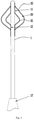
FIG. 1 is a schematic structural diagram of a balloon catheter according to an embodiment of the present invention; -
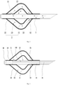
FIG. 2 is a schematic diagram of the flow of a medium in a balloon catheter according to an embodiment of the present invention; -
FIG. 3 is a schematic structuralsectional view 1 of a balloon catheter according to an embodiment of the present invention; and -
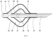
FIG. 4 is a schematic structuralsectional view 2 of a balloon catheter according to an embodiment of the present invention. - 1. catheter; 2. balloon body; 11. outer layer medium inlet hole; 12. medium backflow hole; 13. inner layer medium inlet hole; 14. medium inlet tube; 15. medium backflow tube; 16. guidewire cavity; 17. catheter terminal end; 18. fixing end portion; 19. slidable tube body; 141. control valve; 21. inner layer balloon; 22. outer layer balloon; 23. medium channel; and 24. marking ring.
- The following clearly and completely describes the technical solutions of the present invention with reference to the accompanying drawings. Apparently, the described embodiments are merely some rather than all of the embodiments of the present invention. All other embodiments obtained by persons of ordinary skill in the art based on the embodiments of the present invention without creative efforts shall fall within the protection scope of the present invention.
- In the description of the present invention, it needs to be understood that orientation or location relationships indicated by terms "center", "up", "down", "left", "right", "vertical", "horizontal", "inside", and "outside" are based on orientation or location relationships shown in the accompanying drawings, and are only used to facilitate description of the present invention and simplify description, but are not used to indicate or imply that the apparatuses or elements must have specific orientations or are constructed and operated by using specific orientations, and therefore, cannot be understood as a limitation to the present invention. In addition, the terms "first", "second", and "third" are used only for description, but are not intended to indicate or imply relative importance.
- In the description of the present invention, it needs to be noted that unless otherwise expressly specified and defined, "mounted", "connected", and "connection", should be understood in a broad sense, for example, fixedly connected, detachably connected or integrally connected; or mechanically connected or electrically connected; or connected directly or indirectly through an intermediate, or two elements communicated internally. For a person of ordinary skill in the art, specific meanings of the terms in the present invention should be understood according to specific conditions.
- In addition, the technical features involved in different embodiments of the present invention described below can be combined with each other as long as they do not constitute a conflict between them.
- Referring to
FIG. 1 andFIG. 2 together, a balloon catheter provided in the present invention is described. The balloon catheter includes acatheter 1 and aballoon body 2 sleeved on thecatheter 1. Theballoon body 2 includes aninner layer balloon 21 and anouter layer balloon 22. Theinner layer balloon 21 and theouter layer balloon 22 are both directly wrapped and fixed on thecatheter 1. Theinner layer balloon 21 is located inside theouter layer balloon 22. Amedium channel 23 is formed between theinner layer balloon 21 and theouter layer balloon 22. An outer layermedium inlet hole 11 and amedium backflow hole 12 both in communication with themedium channel 23 are provided in thecatheter 1. - In the balloon catheter provided in the present invention, compared with the prior art, the double-
layer balloon body 2 is provided, so that a medium can flow in themedium channel 23 between theinner layer balloon 21 and theouter layer balloon 22, the medium flows into themedium channel 23 through the outer layermedium inlet hole 11, and then the medium in themedium channel 23 flows out through themedium backflow hole 12 to implement circulation of the medium. In this way, more medium can exchange heat on the inner surface of theouter layer balloon 22 and the flow rate distribution is relatively uniform, to increase the flowing quality of the medium on the surface of theballoon body 2, thereby improving the heat exchange efficiency. - Specifically, the
balloon body 2 is directly sleeved on thecatheter 1. Theballoon body 2 is generally disposed at a terminal end of thecatheter 1. Theballoon body 2 is expandable under the filling of the medium, to fill and support narrow places such as blood vessels, trachea and urethra. Middle parts of theinner layer balloon 21 and theouter layer balloon 22 can both swell after the medium is filled, theinner layer balloon 21 and theouter layer balloon 22 are generally the same in shape, and there is the same distance between the outer surface of theinner layer balloon 21 and the inner surface of theouter layer balloon 22, to ensure that the entiremedium channel 23 has the same channel size, thereby ensuring relatively uniform flow rate distribution of the medium. Certainly, according to an actual case and specific requirements, in other embodiments of the present invention, theinner layer balloon 21 and theouter layer balloon 22 may have different shapes. This is not uniquely limited herein. - Further, referring to
FIG. 1 to FIG. 3 together, in a specific implementation of the balloon catheter provided in the present invention, and an inner layermedium inlet hole 13 in communication with theinner layer balloon 21 is further provided in thecatheter 1. Specifically, the medium may flow through the inner layermedium inlet hole 13 into theinner layer balloon 21, to ensure that the medium can fill theinner layer balloon 21. The medium filling theinner layer balloon 21 and the medium filling theouter layer balloon 22 are generally the same medium. A through hole is directly provided in a sidewall of thecatheter 1, so that the medium located in thecatheter 1 may flow into theinner layer balloon 21. - Preferably, there may be a plurality of inner layer medium inlet holes 13, a plurality of outer layer medium inlet holes 11, and a plurality of medium backflow holes 12, which are evenly distributed in the sidewall of the
catheter 1, so that the speed at which the medium in thecatheter 1 flows into theballoon body 2 can be increased, and it can be ensured that the flow rate of the medium in theouter layer balloon 22 is uniform. - Further, referring to
FIG. 1 to FIG. 3 , in a specific implementation of the balloon catheter provided in the present invention, amedium inlet tube 14 and amedium backflow tube 15 are provided in thecatheter 1. The inner layermedium inlet hole 13 and the outer layermedium inlet hole 11 are both in communication with themedium inlet tube 14. Themedium backflow tube 15 is in communication with themedium backflow hole 12. Specifically, themedium inlet tube 14 and themedium backflow tube 15 are two separate tube bodies, and themedium inlet tube 14 and themedium backflow tube 15 are both in direct communication with an outer side of thecatheter 1. Themedium inlet tube 14 may be in direct communication with the inner layermedium inlet hole 13 and the outer layermedium inlet hole 11. Both the medium in theinner layer balloon 21 and the medium in theouter layer balloon 22 are transported through themedium inlet tube 14. The medium in theouter layer balloon 22 flows through themedium channel 23 and flows out through themedium backflow hole 12 to themedium backflow tube 15 to implement the circulation of all the medium. Certainly, according to an actual case and specific requirements, in other embodiments of the present invention, themedium inlet tube 14 may be only in communication with the outer layermedium inlet hole 11. The medium required for theinner layer balloon 21 may be directly transported by a separate tube body. This is not uniquely limited herein. - Further, referring to
FIG. 1 to FIG. 3 , in a specific implementation of the balloon catheter provided in the present invention, acontrol valve 141 is disposed on themedium inlet tube 14. Thecontrol valve 141 is located between the inner layermedium inlet hole 13 and the outer layermedium inlet hole 11. Specifically, thecontrol valve 141 can control the flow direction of the medium, to ensure that the medium first flows from themedium inlet tube 14 to theinner layer balloon 21, and then, when the pressure in theinner layer balloon 21 is greater than a threshold, thecontrol valve 141 is opened to allow the medium to flow to the outer layermedium inlet hole 11 to fill theouter layer balloon 22, thereby avoiding the problem that the medium directly enters theouter layer balloon 22 for circulation and fails to fill theinner layer balloon 21. - Further, referring to
FIG. 1 to FIG. 3 , in a specific implementation of the balloon catheter provided in the present invention, thecontrol valve 141 is a throttle check valve. Specifically, a throttle valve and a check valve may be combined into a throttle check valve. The throttle valve can open under the action of pressure, and the throttle valve allows one direction, so that the medium can only flow through the inner layermedium inlet hole 13 to enter the outer layermedium inlet hole 11. The backflow of the medium can be effectively avoided. The throttle check valve can ensure the use stability of the balloon catheter, to ensure that the medium fills theinner layer balloon 21 before the medium can fill theouter layer balloon 22, thereby avoiding direct backflow of the medium in theouter layer balloon 22. - Further, referring to
FIG. 1 to FIG. 3 , in a specific implementation of the balloon catheter provided in the present invention, themedium inlet tube 14 and themedium backflow tube 15 are located on two opposite sides on an inner side of thecatheter 1. Specifically, themedium inlet tube 14 and themedium backflow tube 15 are located on the inner side of thecatheter 1, and themedium inlet tube 14 and themedium backflow tube 15 are both located on a side of thecatheter 1 close to a sidewall, so that connections between the inner layermedium inlet hole 13, the outer layermedium inlet hole 11, and themedium backflow hole 12 can be conveniently implemented, and the connections can be implemented by directly opening through holes in themedium inlet tube 14 or themedium backflow tube 15. Certainly, according to an actual case and specific requirements, in other embodiments of the present invention, themedium inlet tube 14 and themedium backflow tube 15 may be directly filled inside thecatheter 1, or themedium inlet tube 14 and themedium backflow tube 15 may be tubes independent of thecatheter 1, or all channels are designed into a composite multi-cavity tube. This is not uniquely limited herein. - Further, referring to
FIG. 1 to FIG. 3 , in a specific implementation of the balloon catheter provided in the present invention, an end of themedium inlet tube 14 is a catheterterminal end 17. The outer layermedium inlet hole 11 is located at one end of theouter layer balloon 22 away from the catheterterminal end 17. The inner layermedium inlet hole 13 is located on a side of the outer layermedium inlet hole 11 close to the catheterterminal end 17. Specifically, an end of thecatheter 1 is the catheterterminal end 17. The catheterterminal end 17 may be an inlet end for the medium and an insertion end for a guidewire. The inner layermedium inlet hole 13 is located near the catheterterminal end 17. That is, the medium fills theinner layer balloon 21 before the medium can fill theouter layer balloon 22, to avoid that all the medium flows into theouter layer balloon 22 to flow out through themedium backflow hole 12, thereby ensuring that both the inner layer and the outer layer of theballoon body 2 can be filled. Certainly, according to an actual case and specific requirements, in other embodiments of the present invention, when an inner layer medium tube is separately disposed, the positions of the inner layermedium inlet hole 13 and the outer layermedium inlet hole 11 may be adjusted as required. This is not uniquely limited herein. - Further, referring to
FIG. 1 to FIG. 3 , in a specific implementation of the balloon catheter provided in the present invention, themedium backflow hole 12 is located at the other end of theouter layer balloon 22 close to the catheterterminal end 17. Specifically, themedium backflow hole 12 and the outer layermedium inlet hole 11 are separately are located at two opposite ends of theouter layer balloon 22, to ensure that the medium can form complete circulation in theouter layer balloon 22, thereby avoiding that the medium fails to completely fill theouter layer balloon 22, so that it is avoided that the support and fixation are inadequate because theouter layer balloon 22 fails to fully expand. Certainly, according to an actual case and specific requirements, in other embodiments of the present invention, a throttle valve may be disposed at themedium backflow hole 12. The medium can flow back through themedium backflow hole 12 only when the pressure in theouter layer balloon 22 is greater than a particular degree. This is not uniquely limited herein. - Further, referring to
FIG. 1 to FIG. 3 , in a specific implementation of the balloon catheter provided in the present invention, aguidewire cavity 16 is further disposed in thecatheter 1. Specifically, theguidewire cavity 16 has assistant functions such as threading a guidewire and introducing a liquid. Theguidewire cavity 16 is usually located at the middle part of thecatheter 1, themedium inlet tube 14 and themedium backflow tube 15 are both located on two sides of theguidewire cavity 16, and a space for theguidewire cavity 16 is reserved in thecatheter 1, to allow for increased applicability and increased functionality of the balloon catheter. - Further, referring to
FIG. 3 andFIG. 4 , in a specific implementation of the balloon catheter provided in the present invention, theguidewire cavity 16 is slidably connected to thecatheter 1, and an end of theguidewire cavity 16 away from the catheterterminal end 17 is fixedly connected to one end of theouter layer balloon 22 away from the catheterterminal end 17. Specifically, thecatheter 1 has a long tube body. Theguidewire cavity 16 is provided inside thecatheter 1. Theguidewire cavity 16 may slide relatively inside thecatheter 1. The end of theguidewire cavity 16 away from the catheterterminal end 17 may be directly fixedly connected to the end of theouter layer balloon 22 away from the catheterterminal end 17. The other end of theouter layer balloon 22 close to the catheterterminal end 17 is fixedly connected to thecatheter 1, so that a spacing between two ends of theouter layer balloon 22 can be changed. When the spacing between the two ends of theouter layer balloon 22 increases, theouter layer balloon 22 has an increased side length and is attached to the outer side of thecatheter 1, to further facilitate interventional treatment with the entire balloon catheter. When the spacing between the two ends of theouter layer balloon 22 decreases, theouter layer balloon 22 can be filled to provide support. - Further, referring to
FIG. 3 andFIG. 4 , in a specific implementation of the balloon catheter provided in the present invention, a markingring 24 is disposed inside theinner layer balloon 21 or theouter layer balloon 22. Specifically, the markingring 24 is disposed inside theballoon body 2 and may mark the position of theballoon body 2 to facilitate observation from outside. The markingring 24 is generally disposed inside theinner layer balloon 21 or theouter layer balloon 22. The markingring 24 is annularly disposed on the outer side of thecatheter 1 to implement the fixation of the markingring 24. The material of the markingring 24 is usually a platinum-iridium alloy or another alloy material that can implement marking. - In another embodiment of the present invention, referring to
FIG. 1 to FIG. 3 , differences between this embodiment andEmbodiment 1 are as follows: Amedium inlet tube 14, amedium backflow tube 15, and an inner layer medium tube (not shown in the figure) are disposed in thecatheter 1, the inner layermedium inlet hole 13 is in communication with the inner layer medium tube, the outer layermedium inlet hole 11 is in communication with themedium inlet tube 14, and themedium backflow tube 15 is in communication with themedium backflow hole 12. Specifically, themedium inlet tube 14, themedium backflow tube 15, and the inner layer medium tube are all separate tube bodies, and the inner layermedium inlet hole 13 is in communication with the inner layer medium tube. Because the inner layer medium tube and themedium inlet tube 14 are two separate tube bodies, it is not necessary to arrange thecontrol valve 141 to control the flow rate, so that the control method is simpler, and a medium can be directly transported for theinner layer balloon 21 and theouter layer balloon 22. The medium in theouter layer balloon 22 flows through themedium channel 23 and flows out through themedium backflow hole 12 to themedium backflow tube 15 to implement the circulation of all the medium. - Obviously, the foregoing embodiments are merely examples for clear description, rather than a limitation to implementations. For a person of ordinary skill in the art, other changes or variations in different forms may also be made based on the foregoing description. All implementations cannot and do not need to be exhaustively listed herein. Obvious changes or variations that are derived there from still fall within the protection scope of the invention of the present invention.
Claims (10)
- A balloon catheter, comprising a catheter (1) and a balloon body (2) sleeved on the catheter (1), wherein the balloon body (2) comprises an inner layer balloon (21) and an outer layer balloon (22), the inner layer balloon (21) and the outer layer balloon (22) are both directly wrapped and fixed on the catheter (1), the inner layer balloon (21) is located inside the outer layer balloon (22), a medium channel (23) is formed between the inner layer balloon (21) and the outer layer balloon (22), and an outer layer medium inlet hole (11) and a medium backflow hole (12) both in communication with the medium channel (23) are provided in the catheter (1).
- The balloon catheter according to claim 1, wherein an inner layer medium inlet hole (13) in communication with the inner layer balloon (21) is further provided in the catheter (1).
- The balloon catheter according to claim 2, wherein a medium inlet tube (14) and a medium backflow tube (15) are provided in the catheter (1), the inner layer medium inlet hole (13) and the outer layer medium inlet hole (11) are both in communication with the medium inlet tube (14), and the medium backflow tube (15) is in communication with the medium backflow hole (12).
- The balloon catheter according to claim 3, wherein a control valve (141) is disposed on the medium inlet tube (14), and the control valve (141) is located between the inner layer medium inlet hole (13) and the outer layer medium inlet hole (11).
- The balloon catheter according to claim 2, wherein a medium inlet tube (14), a medium backflow tube (15), and an inner layer medium tube are disposed in the catheter (1), the inner layer medium inlet hole (13) is in communication with the inner layer medium tube, the outer layer medium inlet hole (11) is in communication with the medium inlet tube (14), and the medium backflow tube (15) is in communication with the medium backflow hole (12).
- The balloon catheter according to any one of claims 3 to 5, wherein an end of the medium inlet tube (14) is a catheter terminal end (17), the outer layer medium inlet hole (11) is located at one end of the outer layer balloon (22) away from the catheter terminal end (17), and the inner layer medium inlet hole (13) is located on a side of the outer layer medium inlet hole (11) close to the catheter terminal end (17).
- The balloon catheter according to claim 6, wherein the medium backflow hole (12) is located at the other end of the outer layer balloon (22) close to the catheter terminal end (17).
- The balloon catheter according to any one of claims 3 to 5, wherein a guidewire cavity (16) is further disposed in the catheter (1).
- The balloon catheter according to claim 8, wherein the guidewire cavity (16) is slidably connected to the catheter (1), and an end of the guidewire cavity (16) away from a catheter terminal end (17) is fixedly connected to an end of the outer layer balloon (22) away from the catheter terminal end (17).
- The balloon catheter according to claim 1, wherein a marking ring (24) is disposed inside the inner layer balloon (21) or the outer layer balloon (22).
Applications Claiming Priority (2)
| Application Number | Priority Date | Filing Date | Title |
|---|---|---|---|
| CN201910492068.9A CN110115798B (en) | 2019-06-06 | 2019-06-06 | Balloon Catheter |
| PCT/CN2019/118314 WO2020244154A1 (en) | 2019-06-06 | 2019-11-14 | Balloon catheter |
Publications (3)
| Publication Number | Publication Date |
|---|---|
| EP3970782A1 true EP3970782A1 (en) | 2022-03-23 |
| EP3970782A4 EP3970782A4 (en) | 2022-07-06 |
| EP3970782B1 EP3970782B1 (en) | 2025-09-10 |
Family
ID=67523870
Family Applications (1)
| Application Number | Title | Priority Date | Filing Date |
|---|---|---|---|
| EP19931574.8A Active EP3970782B1 (en) | 2019-06-06 | 2019-11-14 | Balloon catheter |
Country Status (5)
| Country | Link |
|---|---|
| US (1) | US12447318B2 (en) |
| EP (1) | EP3970782B1 (en) |
| JP (1) | JP7304099B2 (en) |
| CN (1) | CN110115798B (en) |
| WO (1) | WO2020244154A1 (en) |
Families Citing this family (5)
| Publication number | Priority date | Publication date | Assignee | Title |
|---|---|---|---|---|
| CN110115798B (en) * | 2019-06-06 | 2024-09-06 | 山前(珠海)医疗科技有限公司 | Balloon Catheter |
| CN111281527A (en) * | 2020-01-13 | 2020-06-16 | 珠海大横琴科技发展有限公司 | cryoablation catheter |
| CN119184830B (en) * | 2024-09-23 | 2025-09-23 | 宁波胜杰康生物科技有限公司 | A cryoballoon catheter |
| CN119587848B (en) * | 2024-12-12 | 2025-10-03 | 苏州大学附属第一医院 | A balloon catheter suitable for longer vascular lesions |
| CN121371445B (en) * | 2025-11-21 | 2026-05-08 | 中国医学科学院阜外医院 | A multi-level adjustable pulmonary vascular interventional balloon catheter |
Family Cites Families (23)
| Publication number | Priority date | Publication date | Assignee | Title |
|---|---|---|---|---|
| US4649914A (en) * | 1985-11-12 | 1987-03-17 | Kowalewski Ryszard J | Rapid self-inflating tracheal tube with constant pressure control feature |
| EP0379794A1 (en) | 1989-01-27 | 1990-08-01 | C.R. Bard, Inc. | Fast purge balloon dilatation catheter |
| JPH05506174A (en) * | 1990-09-14 | 1993-09-16 | アメリカン・メディカル・システムズ・インコーポレーテッド | Combined hyperthermia and dilatation catheter |
| US6419643B1 (en) * | 1998-04-21 | 2002-07-16 | Alsius Corporation | Central venous catheter with heat exchange properties |
| US6610083B2 (en) | 1998-08-24 | 2003-08-26 | Radiant Medical, Inc. | Multiple lumen heat exchange catheters |
| US6471672B1 (en) * | 1999-11-10 | 2002-10-29 | Scimed Life Systems | Selective high pressure dilation balloon |
| US7144407B1 (en) * | 2002-05-30 | 2006-12-05 | Alsius Corporation | Cardiovascular intra aortic balloon pump catheter with heat exchange function and methods of use |
| EP2195070A4 (en) * | 2007-05-30 | 2011-10-26 | Critical Care Innovations Inc | METHOD AND DEVICE FOR SELECTIVELY PROCESSING INTERSTITIAL FABRIC |
| US8034022B2 (en) * | 2008-04-08 | 2011-10-11 | Cook Medical Technologies Llc | Weeping balloon catheter |
| EP2110151A1 (en) * | 2008-04-16 | 2009-10-21 | Edward Diethrich | Double balloon occlusion device |
| CN101822866A (en) | 2009-03-02 | 2010-09-08 | 东莞市迪凯精密管材有限公司 | Double-balloon blood vessel dilating catheter |
| JP2011206208A (en) * | 2010-03-29 | 2011-10-20 | Terumo Corp | Hot balloon catheter, treatment device, and control method thereof |
| US8348890B2 (en) * | 2011-03-01 | 2013-01-08 | Sanovas, Inc. | Nested balloon catheter for localized drug delivery |
| US10441338B2 (en) | 2014-01-14 | 2019-10-15 | Medtronic Cryocath Lp | Balloon catheter with fluid injection elements |
| US10293145B2 (en) * | 2014-09-30 | 2019-05-21 | Piolaz Medical Devices, Inc. | Balloon catheter |
| US10406318B2 (en) * | 2015-05-19 | 2019-09-10 | Abbott Cardiovascular Systems, Inc. | Balloon catheter |
| JP6320978B2 (en) * | 2015-09-28 | 2018-05-09 | 有限会社日本エレクテル | High frequency balloon catheter system |
| CN106880400B (en) * | 2015-12-16 | 2020-10-23 | 上海微创电生理医疗科技股份有限公司 | Electrophysiological catheters and radiofrequency ablation systems |
| US11045128B2 (en) * | 2017-06-03 | 2021-06-29 | Sentinel Medical Technologies, LLC | Catheter for monitoring intra-abdominal pressure |
| CN208541677U (en) * | 2017-09-20 | 2019-02-26 | 柳州市工人医院 | A double layer balloon catheter |
| CN210750823U (en) * | 2019-06-06 | 2020-06-16 | 山前(珠海)医疗科技有限公司 | Balloon catheter |
| CN110115798B (en) * | 2019-06-06 | 2024-09-06 | 山前(珠海)医疗科技有限公司 | Balloon Catheter |
| US20240149020A1 (en) * | 2022-11-04 | 2024-05-09 | Controlled Delivery Systems, Inc. | Catheters for the aspiration controlled delivery of closure agents |
-
2019
- 2019-06-06 CN CN201910492068.9A patent/CN110115798B/en active Active
- 2019-11-14 EP EP19931574.8A patent/EP3970782B1/en active Active
- 2019-11-14 JP JP2021572504A patent/JP7304099B2/en active Active
- 2019-11-14 WO PCT/CN2019/118314 patent/WO2020244154A1/en not_active Ceased
- 2019-11-14 US US17/596,243 patent/US12447318B2/en active Active
Also Published As
| Publication number | Publication date |
|---|---|
| CN110115798B (en) | 2024-09-06 |
| EP3970782A4 (en) | 2022-07-06 |
| US12447318B2 (en) | 2025-10-21 |
| CN110115798A (en) | 2019-08-13 |
| WO2020244154A1 (en) | 2020-12-10 |
| US20220339412A1 (en) | 2022-10-27 |
| JP7304099B2 (en) | 2023-07-06 |
| JP2022536308A (en) | 2022-08-15 |
| EP3970782B1 (en) | 2025-09-10 |
Similar Documents
| Publication | Publication Date | Title |
|---|---|---|
| US12447318B2 (en) | Balloon catheter | |
| US5403274A (en) | Perfusion catheter and method of use | |
| GB2438171A (en) | Tracheo-oesophageal fistula catheter | |
| CN114082085A (en) | Pre-expanding type double-layer drug perfusion balloon dilatation catheter | |
| CN213252431U (en) | An integral exchange type double-layer drug perfusion balloon dilatation catheter | |
| CN219251343U (en) | Balloon dilation catheter | |
| KR20110026292A (en) | Prayer Balloon Catheter | |
| CN102258825A (en) | Percutaneous transluminal coronary angioplasty (PTCA) balloon catheter | |
| CN106492325A (en) | A kind of drainage tube | |
| CN108211091A (en) | A kind of cancer of the esophagus Hyperthermic Chemotherapy conduit | |
| CN209173185U (en) | A kind of double saccule urinary catheters of anti-urethral injury | |
| CN210750823U (en) | Balloon catheter | |
| CN105853035A (en) | Special-type main and side branch saccule stent system for interventional therapy of bifurcation lesions | |
| CN113926058A (en) | Drug release balloon dilatation catheter | |
| WO2013135182A1 (en) | Balloon dilatation catheter | |
| US20150265805A1 (en) | Catheter with Gills | |
| CN115068786B (en) | Medical sheath tube | |
| CN215690904U (en) | Intracavity catheter | |
| CN117065187A (en) | Distance-adjustable double-plugging balloon microcatheter | |
| CN206934434U (en) | A kind of hepatic surgery used saccular dilation guide tube | |
| CN221155065U (en) | Double-layer balloon dilation catheter | |
| CN212416632U (en) | Balloon dilatation catheter | |
| CN209005004U (en) | Urethral catheter dedicated in man | |
| CN214912432U (en) | A super-compliant perfusion balloon | |
| CN107343981A (en) | A kind of sacculus dilating catheter |
Legal Events
| Date | Code | Title | Description |
|---|---|---|---|
| STAA | Information on the status of an ep patent application or granted ep patent |
Free format text: STATUS: THE INTERNATIONAL PUBLICATION HAS BEEN MADE |
|
| PUAI | Public reference made under article 153(3) epc to a published international application that has entered the european phase |
Free format text: ORIGINAL CODE: 0009012 |
|
| STAA | Information on the status of an ep patent application or granted ep patent |
Free format text: STATUS: REQUEST FOR EXAMINATION WAS MADE |
|
| 17P | Request for examination filed |
Effective date: 20211216 |
|
| AK | Designated contracting states |
Kind code of ref document: A1 Designated state(s): AL AT BE BG CH CY CZ DE DK EE ES FI FR GB GR HR HU IE IS IT LI LT LU LV MC MK MT NL NO PL PT RO RS SE SI SK SM TR |
|
| A4 | Supplementary search report drawn up and despatched |
Effective date: 20220603 |
|
| RIC1 | Information provided on ipc code assigned before grant |
Ipc: A61F 7/12 20060101ALI20220530BHEP Ipc: A61M 25/10 20130101AFI20220530BHEP |
|
| DAV | Request for validation of the european patent (deleted) | ||
| DAX | Request for extension of the european patent (deleted) | ||
| GRAP | Despatch of communication of intention to grant a patent |
Free format text: ORIGINAL CODE: EPIDOSNIGR1 |
|
| STAA | Information on the status of an ep patent application or granted ep patent |
Free format text: STATUS: GRANT OF PATENT IS INTENDED |
|
| INTG | Intention to grant announced |
Effective date: 20250410 |
|
| GRAS | Grant fee paid |
Free format text: ORIGINAL CODE: EPIDOSNIGR3 |
|
| GRAA | (expected) grant |
Free format text: ORIGINAL CODE: 0009210 |
|
| STAA | Information on the status of an ep patent application or granted ep patent |
Free format text: STATUS: THE PATENT HAS BEEN GRANTED |
|
| AK | Designated contracting states |
Kind code of ref document: B1 Designated state(s): AL AT BE BG CH CY CZ DE DK EE ES FI FR GB GR HR HU IE IS IT LI LT LU LV MC MK MT NL NO PL PT RO RS SE SI SK SM TR |
|
| REG | Reference to a national code |
Ref country code: GB Ref legal event code: FG4D |
|
| REG | Reference to a national code |
Ref country code: CH Ref legal event code: EP |
|
| REG | Reference to a national code |
Ref country code: DE Ref legal event code: R096 Ref document number: 602019075692 Country of ref document: DE |
|
| REG | Reference to a national code |
Ref country code: IE Ref legal event code: FG4D |
|
| PGFP | Annual fee paid to national office [announced via postgrant information from national office to epo] |
Ref country code: GB Payment date: 20251226 Year of fee payment: 7 |
|
| PG25 | Lapsed in a contracting state [announced via postgrant information from national office to epo] |
Ref country code: NO Free format text: LAPSE BECAUSE OF FAILURE TO SUBMIT A TRANSLATION OF THE DESCRIPTION OR TO PAY THE FEE WITHIN THE PRESCRIBED TIME-LIMIT Effective date: 20251210 |
|
| REG | Reference to a national code |
Ref country code: LT Ref legal event code: MG9D |
|
| PG25 | Lapsed in a contracting state [announced via postgrant information from national office to epo] |
Ref country code: FI Free format text: LAPSE BECAUSE OF FAILURE TO SUBMIT A TRANSLATION OF THE DESCRIPTION OR TO PAY THE FEE WITHIN THE PRESCRIBED TIME-LIMIT Effective date: 20250910 |
|
| REG | Reference to a national code |
Ref country code: NL Ref legal event code: MP Effective date: 20250910 |
|
| PG25 | Lapsed in a contracting state [announced via postgrant information from national office to epo] |
Ref country code: HR Free format text: LAPSE BECAUSE OF FAILURE TO SUBMIT A TRANSLATION OF THE DESCRIPTION OR TO PAY THE FEE WITHIN THE PRESCRIBED TIME-LIMIT Effective date: 20250910 |
|
| PGFP | Annual fee paid to national office [announced via postgrant information from national office to epo] |
Ref country code: FR Payment date: 20251128 Year of fee payment: 7 |
|
| PG25 | Lapsed in a contracting state [announced via postgrant information from national office to epo] |
Ref country code: GR Free format text: LAPSE BECAUSE OF FAILURE TO SUBMIT A TRANSLATION OF THE DESCRIPTION OR TO PAY THE FEE WITHIN THE PRESCRIBED TIME-LIMIT Effective date: 20251211 |
|
| PG25 | Lapsed in a contracting state [announced via postgrant information from national office to epo] |
Ref country code: SE Free format text: LAPSE BECAUSE OF FAILURE TO SUBMIT A TRANSLATION OF THE DESCRIPTION OR TO PAY THE FEE WITHIN THE PRESCRIBED TIME-LIMIT Effective date: 20250910 |
|
| PG25 | Lapsed in a contracting state [announced via postgrant information from national office to epo] |
Ref country code: LV Free format text: LAPSE BECAUSE OF FAILURE TO SUBMIT A TRANSLATION OF THE DESCRIPTION OR TO PAY THE FEE WITHIN THE PRESCRIBED TIME-LIMIT Effective date: 20250910 |
|
| PG25 | Lapsed in a contracting state [announced via postgrant information from national office to epo] |
Ref country code: BG Free format text: LAPSE BECAUSE OF FAILURE TO SUBMIT A TRANSLATION OF THE DESCRIPTION OR TO PAY THE FEE WITHIN THE PRESCRIBED TIME-LIMIT Effective date: 20250910 Ref country code: PL Free format text: LAPSE BECAUSE OF FAILURE TO SUBMIT A TRANSLATION OF THE DESCRIPTION OR TO PAY THE FEE WITHIN THE PRESCRIBED TIME-LIMIT Effective date: 20250910 |
|
| PG25 | Lapsed in a contracting state [announced via postgrant information from national office to epo] |
Ref country code: RS Free format text: LAPSE BECAUSE OF FAILURE TO SUBMIT A TRANSLATION OF THE DESCRIPTION OR TO PAY THE FEE WITHIN THE PRESCRIBED TIME-LIMIT Effective date: 20251210 |
|
| PG25 | Lapsed in a contracting state [announced via postgrant information from national office to epo] |
Ref country code: ES Free format text: LAPSE BECAUSE OF FAILURE TO SUBMIT A TRANSLATION OF THE DESCRIPTION OR TO PAY THE FEE WITHIN THE PRESCRIBED TIME-LIMIT Effective date: 20250910 |
|
| REG | Reference to a national code |
Ref country code: AT Ref legal event code: MK05 Ref document number: 1835254 Country of ref document: AT Kind code of ref document: T Effective date: 20250910 |
|
| PG25 | Lapsed in a contracting state [announced via postgrant information from national office to epo] |
Ref country code: NL Free format text: LAPSE BECAUSE OF FAILURE TO SUBMIT A TRANSLATION OF THE DESCRIPTION OR TO PAY THE FEE WITHIN THE PRESCRIBED TIME-LIMIT Effective date: 20250910 |
|
| PG25 | Lapsed in a contracting state [announced via postgrant information from national office to epo] |
Ref country code: SM Free format text: LAPSE BECAUSE OF FAILURE TO SUBMIT A TRANSLATION OF THE DESCRIPTION OR TO PAY THE FEE WITHIN THE PRESCRIBED TIME-LIMIT Effective date: 20250910 |
|
| PGFP | Annual fee paid to national office [announced via postgrant information from national office to epo] |
Ref country code: DE Payment date: 20251231 Year of fee payment: 7 |
|
| PG25 | Lapsed in a contracting state [announced via postgrant information from national office to epo] |
Ref country code: AT Free format text: LAPSE BECAUSE OF FAILURE TO SUBMIT A TRANSLATION OF THE DESCRIPTION OR TO PAY THE FEE WITHIN THE PRESCRIBED TIME-LIMIT Effective date: 20250910 |
|
| PG25 | Lapsed in a contracting state [announced via postgrant information from national office to epo] |
Ref country code: RO Free format text: LAPSE BECAUSE OF FAILURE TO SUBMIT A TRANSLATION OF THE DESCRIPTION OR TO PAY THE FEE WITHIN THE PRESCRIBED TIME-LIMIT Effective date: 20250910 Ref country code: IT Free format text: LAPSE BECAUSE OF FAILURE TO SUBMIT A TRANSLATION OF THE DESCRIPTION OR TO PAY THE FEE WITHIN THE PRESCRIBED TIME-LIMIT Effective date: 20250910 |
|
| PG25 | Lapsed in a contracting state [announced via postgrant information from national office to epo] |
Ref country code: IS Free format text: LAPSE BECAUSE OF FAILURE TO SUBMIT A TRANSLATION OF THE DESCRIPTION OR TO PAY THE FEE WITHIN THE PRESCRIBED TIME-LIMIT Effective date: 20260110 |
|
| PG25 | Lapsed in a contracting state [announced via postgrant information from national office to epo] |
Ref country code: PT Free format text: LAPSE BECAUSE OF FAILURE TO SUBMIT A TRANSLATION OF THE DESCRIPTION OR TO PAY THE FEE WITHIN THE PRESCRIBED TIME-LIMIT Effective date: 20260112 Ref country code: CZ Free format text: LAPSE BECAUSE OF FAILURE TO SUBMIT A TRANSLATION OF THE DESCRIPTION OR TO PAY THE FEE WITHIN THE PRESCRIBED TIME-LIMIT Effective date: 20250910 |
|
| PG25 | Lapsed in a contracting state [announced via postgrant information from national office to epo] |
Ref country code: EE Free format text: LAPSE BECAUSE OF FAILURE TO SUBMIT A TRANSLATION OF THE DESCRIPTION OR TO PAY THE FEE WITHIN THE PRESCRIBED TIME-LIMIT Effective date: 20250910 Ref country code: SK Free format text: LAPSE BECAUSE OF FAILURE TO SUBMIT A TRANSLATION OF THE DESCRIPTION OR TO PAY THE FEE WITHIN THE PRESCRIBED TIME-LIMIT Effective date: 20250910 |