EP3970780A1 - Light-irradiation device and light-irradiation system - Google Patents
Light-irradiation device and light-irradiation system Download PDFInfo
- Publication number
- EP3970780A1 EP3970780A1 EP20804765.4A EP20804765A EP3970780A1 EP 3970780 A1 EP3970780 A1 EP 3970780A1 EP 20804765 A EP20804765 A EP 20804765A EP 3970780 A1 EP3970780 A1 EP 3970780A1
- Authority
- EP
- European Patent Office
- Prior art keywords
- light irradiation
- light
- end side
- irradiation device
- main body
- Prior art date
- Legal status (The legal status is an assumption and is not a legal conclusion. Google has not performed a legal analysis and makes no representation as to the accuracy of the status listed.)
- Withdrawn
Links
- 239000003550 marker Substances 0.000 claims abstract description 194
- 238000010586 diagram Methods 0.000 description 27
- 239000000463 material Substances 0.000 description 27
- 229920005989 resin Polymers 0.000 description 27
- 239000011347 resin Substances 0.000 description 27
- 206010028980 Neoplasm Diseases 0.000 description 21
- 201000011510 cancer Diseases 0.000 description 19
- 238000000034 method Methods 0.000 description 19
- 210000004027 cell Anatomy 0.000 description 16
- 238000003780 insertion Methods 0.000 description 14
- 230000037431 insertion Effects 0.000 description 14
- 230000000694 effects Effects 0.000 description 13
- 239000007769 metal material Substances 0.000 description 11
- 210000001519 tissue Anatomy 0.000 description 11
- 238000002428 photodynamic therapy Methods 0.000 description 10
- 230000004048 modification Effects 0.000 description 9
- 238000012986 modification Methods 0.000 description 9
- 238000011282 treatment Methods 0.000 description 8
- 239000000126 substance Substances 0.000 description 7
- 238000004804 winding Methods 0.000 description 6
- 230000001678 irradiating effect Effects 0.000 description 5
- 230000008569 process Effects 0.000 description 5
- 238000005452 bending Methods 0.000 description 4
- 210000004907 gland Anatomy 0.000 description 4
- 239000013307 optical fiber Substances 0.000 description 4
- 210000004204 blood vessel Anatomy 0.000 description 3
- 230000006378 damage Effects 0.000 description 3
- -1 for example Substances 0.000 description 3
- 238000004519 manufacturing process Methods 0.000 description 3
- 230000001629 suppression Effects 0.000 description 3
- WFKWXMTUELFFGS-UHFFFAOYSA-N tungsten Chemical compound [W] WFKWXMTUELFFGS-UHFFFAOYSA-N 0.000 description 3
- 229910052721 tungsten Inorganic materials 0.000 description 3
- 239000010937 tungsten Substances 0.000 description 3
- XUIMIQQOPSSXEZ-UHFFFAOYSA-N Silicon Chemical compound [Si] XUIMIQQOPSSXEZ-UHFFFAOYSA-N 0.000 description 2
- 238000009825 accumulation Methods 0.000 description 2
- TZCXTZWJZNENPQ-UHFFFAOYSA-L barium sulfate Chemical compound [Ba+2].[O-]S([O-])(=O)=O TZCXTZWJZNENPQ-UHFFFAOYSA-L 0.000 description 2
- 210000003445 biliary tract Anatomy 0.000 description 2
- 230000017531 blood circulation Effects 0.000 description 2
- 239000011248 coating agent Substances 0.000 description 2
- 238000000576 coating method Methods 0.000 description 2
- 210000002249 digestive system Anatomy 0.000 description 2
- 229940079593 drug Drugs 0.000 description 2
- 239000003814 drug Substances 0.000 description 2
- 230000005284 excitation Effects 0.000 description 2
- 238000003384 imaging method Methods 0.000 description 2
- 210000002751 lymph Anatomy 0.000 description 2
- 210000000056 organ Anatomy 0.000 description 2
- BASFCYQUMIYNBI-UHFFFAOYSA-N platinum Chemical compound [Pt] BASFCYQUMIYNBI-UHFFFAOYSA-N 0.000 description 2
- 229920006122 polyamide resin Polymers 0.000 description 2
- 229920001225 polyester resin Polymers 0.000 description 2
- 239000004645 polyester resin Substances 0.000 description 2
- 229920005672 polyolefin resin Polymers 0.000 description 2
- 229920005749 polyurethane resin Polymers 0.000 description 2
- 239000000843 powder Substances 0.000 description 2
- 230000001850 reproductive effect Effects 0.000 description 2
- 230000003248 secreting effect Effects 0.000 description 2
- 229910052710 silicon Inorganic materials 0.000 description 2
- 239000010703 silicon Substances 0.000 description 2
- 230000000451 tissue damage Effects 0.000 description 2
- 231100000827 tissue damage Toxicity 0.000 description 2
- 238000013519 translation Methods 0.000 description 2
- 210000001635 urinary tract Anatomy 0.000 description 2
- 230000002792 vascular Effects 0.000 description 2
- 229920000178 Acrylic resin Polymers 0.000 description 1
- 239000004925 Acrylic resin Substances 0.000 description 1
- YCKRFDGAMUMZLT-UHFFFAOYSA-N Fluorine atom Chemical compound [F] YCKRFDGAMUMZLT-UHFFFAOYSA-N 0.000 description 1
- HTTJABKRGRZYRN-UHFFFAOYSA-N Heparin Chemical compound OC1C(NC(=O)C)C(O)OC(COS(O)(=O)=O)C1OC1C(OS(O)(=O)=O)C(O)C(OC2C(C(OS(O)(=O)=O)C(OC3C(C(O)C(O)C(O3)C(O)=O)OS(O)(=O)=O)C(CO)O2)NS(O)(=O)=O)C(C(O)=O)O1 HTTJABKRGRZYRN-UHFFFAOYSA-N 0.000 description 1
- 229910000990 Ni alloy Inorganic materials 0.000 description 1
- 229930182556 Polyacetal Natural products 0.000 description 1
- 239000004952 Polyamide Substances 0.000 description 1
- 239000004695 Polyether sulfone Substances 0.000 description 1
- 239000004743 Polypropylene Substances 0.000 description 1
- 229910000831 Steel Inorganic materials 0.000 description 1
- 208000007536 Thrombosis Diseases 0.000 description 1
- WAIPAZQMEIHHTJ-UHFFFAOYSA-N [Cr].[Co] Chemical class [Cr].[Co] WAIPAZQMEIHHTJ-UHFFFAOYSA-N 0.000 description 1
- NIXOWILDQLNWCW-UHFFFAOYSA-N acrylic acid group Chemical group C(C=C)(=O)O NIXOWILDQLNWCW-UHFFFAOYSA-N 0.000 description 1
- 229910045601 alloy Inorganic materials 0.000 description 1
- 239000000956 alloy Substances 0.000 description 1
- 230000001093 anti-cancer Effects 0.000 description 1
- 230000002965 anti-thrombogenic effect Effects 0.000 description 1
- 230000002785 anti-thrombosis Effects 0.000 description 1
- 239000003146 anticoagulant agent Substances 0.000 description 1
- 239000000427 antigen Substances 0.000 description 1
- 102000036639 antigens Human genes 0.000 description 1
- 108091007433 antigens Proteins 0.000 description 1
- WMWLMWRWZQELOS-UHFFFAOYSA-N bismuth(III) oxide Inorganic materials O=[Bi]O[Bi]=O WMWLMWRWZQELOS-UHFFFAOYSA-N 0.000 description 1
- 230000023555 blood coagulation Effects 0.000 description 1
- 230000005779 cell damage Effects 0.000 description 1
- 208000037887 cell injury Diseases 0.000 description 1
- 230000008859 change Effects 0.000 description 1
- 238000005253 cladding Methods 0.000 description 1
- 150000001875 compounds Chemical class 0.000 description 1
- 238000011161 development Methods 0.000 description 1
- 239000000835 fiber Substances 0.000 description 1
- 229910052731 fluorine Inorganic materials 0.000 description 1
- 239000011737 fluorine Substances 0.000 description 1
- PCHJSUWPFVWCPO-UHFFFAOYSA-N gold Chemical compound [Au] PCHJSUWPFVWCPO-UHFFFAOYSA-N 0.000 description 1
- 229910052737 gold Inorganic materials 0.000 description 1
- 239000010931 gold Substances 0.000 description 1
- 239000008187 granular material Substances 0.000 description 1
- 229960002897 heparin Drugs 0.000 description 1
- 229920000669 heparin Polymers 0.000 description 1
- 230000002209 hydrophobic effect Effects 0.000 description 1
- 210000000987 immune system Anatomy 0.000 description 1
- 238000001727 in vivo Methods 0.000 description 1
- 230000031700 light absorption Effects 0.000 description 1
- 230000014759 maintenance of location Effects 0.000 description 1
- 239000012528 membrane Substances 0.000 description 1
- PCLURTMBFDTLSK-UHFFFAOYSA-N nickel platinum Chemical compound [Ni].[Pt] PCLURTMBFDTLSK-UHFFFAOYSA-N 0.000 description 1
- 229910001000 nickel titanium Inorganic materials 0.000 description 1
- 230000035515 penetration Effects 0.000 description 1
- 230000000144 pharmacologic effect Effects 0.000 description 1
- 229910052697 platinum Inorganic materials 0.000 description 1
- 229920002647 polyamide Polymers 0.000 description 1
- 229920000515 polycarbonate Polymers 0.000 description 1
- 239000004417 polycarbonate Substances 0.000 description 1
- 229920006393 polyether sulfone Polymers 0.000 description 1
- 229920000139 polyethylene terephthalate Polymers 0.000 description 1
- 239000005020 polyethylene terephthalate Substances 0.000 description 1
- 229920006324 polyoxymethylene Polymers 0.000 description 1
- 229920001155 polypropylene Polymers 0.000 description 1
- 229920002635 polyurethane Polymers 0.000 description 1
- 239000004814 polyurethane Substances 0.000 description 1
- 229920003225 polyurethane elastomer Polymers 0.000 description 1
- 229920000915 polyvinyl chloride Polymers 0.000 description 1
- 239000004800 polyvinyl chloride Substances 0.000 description 1
- 239000010453 quartz Substances 0.000 description 1
- 239000003642 reactive oxygen metabolite Substances 0.000 description 1
- 210000003289 regulatory T cell Anatomy 0.000 description 1
- 230000003014 reinforcing effect Effects 0.000 description 1
- 238000005488 sandblasting Methods 0.000 description 1
- VYPSYNLAJGMNEJ-UHFFFAOYSA-N silicon dioxide Inorganic materials O=[Si]=O VYPSYNLAJGMNEJ-UHFFFAOYSA-N 0.000 description 1
- 239000007787 solid Substances 0.000 description 1
- 239000010935 stainless steel Substances 0.000 description 1
- 229910001220 stainless steel Inorganic materials 0.000 description 1
- 239000010959 steel Substances 0.000 description 1
- 230000008685 targeting Effects 0.000 description 1
- 230000001225 therapeutic effect Effects 0.000 description 1
- 239000010409 thin film Substances 0.000 description 1
Images






Classifications
-
- A—HUMAN NECESSITIES
- A61—MEDICAL OR VETERINARY SCIENCE; HYGIENE
- A61N—ELECTROTHERAPY; MAGNETOTHERAPY; RADIATION THERAPY; ULTRASOUND THERAPY
- A61N5/00—Radiation therapy
- A61N5/06—Radiation therapy using light
- A61N5/0601—Apparatus for use inside the body
-
- A—HUMAN NECESSITIES
- A61—MEDICAL OR VETERINARY SCIENCE; HYGIENE
- A61B—DIAGNOSIS; SURGERY; IDENTIFICATION
- A61B18/00—Surgical instruments, devices or methods for transferring non-mechanical forms of energy to or from the body
- A61B18/18—Surgical instruments, devices or methods for transferring non-mechanical forms of energy to or from the body by applying electromagnetic radiation, e.g. microwaves
- A61B18/20—Surgical instruments, devices or methods for transferring non-mechanical forms of energy to or from the body by applying electromagnetic radiation, e.g. microwaves using laser
- A61B18/22—Surgical instruments, devices or methods for transferring non-mechanical forms of energy to or from the body by applying electromagnetic radiation, e.g. microwaves using laser the beam being directed along or through a flexible conduit, e.g. an optical fibre; Couplings or hand-pieces therefor
- A61B18/24—Surgical instruments, devices or methods for transferring non-mechanical forms of energy to or from the body by applying electromagnetic radiation, e.g. microwaves using laser the beam being directed along or through a flexible conduit, e.g. an optical fibre; Couplings or hand-pieces therefor with a catheter
-
- A—HUMAN NECESSITIES
- A61—MEDICAL OR VETERINARY SCIENCE; HYGIENE
- A61N—ELECTROTHERAPY; MAGNETOTHERAPY; RADIATION THERAPY; ULTRASOUND THERAPY
- A61N5/00—Radiation therapy
- A61N5/06—Radiation therapy using light
- A61N5/0613—Apparatus adapted for a specific treatment
- A61N5/062—Photodynamic therapy, i.e. excitation of an agent
-
- A—HUMAN NECESSITIES
- A61—MEDICAL OR VETERINARY SCIENCE; HYGIENE
- A61B—DIAGNOSIS; SURGERY; IDENTIFICATION
- A61B18/00—Surgical instruments, devices or methods for transferring non-mechanical forms of energy to or from the body
- A61B18/18—Surgical instruments, devices or methods for transferring non-mechanical forms of energy to or from the body by applying electromagnetic radiation, e.g. microwaves
- A61B18/20—Surgical instruments, devices or methods for transferring non-mechanical forms of energy to or from the body by applying electromagnetic radiation, e.g. microwaves using laser
- A61B2018/208—Surgical instruments, devices or methods for transferring non-mechanical forms of energy to or from the body by applying electromagnetic radiation, e.g. microwaves using laser with multiple treatment beams not sharing a common path, e.g. non-axial or parallel
-
- A—HUMAN NECESSITIES
- A61—MEDICAL OR VETERINARY SCIENCE; HYGIENE
- A61B—DIAGNOSIS; SURGERY; IDENTIFICATION
- A61B18/00—Surgical instruments, devices or methods for transferring non-mechanical forms of energy to or from the body
- A61B18/18—Surgical instruments, devices or methods for transferring non-mechanical forms of energy to or from the body by applying electromagnetic radiation, e.g. microwaves
- A61B18/20—Surgical instruments, devices or methods for transferring non-mechanical forms of energy to or from the body by applying electromagnetic radiation, e.g. microwaves using laser
- A61B18/22—Surgical instruments, devices or methods for transferring non-mechanical forms of energy to or from the body by applying electromagnetic radiation, e.g. microwaves using laser the beam being directed along or through a flexible conduit, e.g. an optical fibre; Couplings or hand-pieces therefor
- A61B2018/2255—Optical elements at the distal end of probe tips
- A61B2018/2272—Optical elements at the distal end of probe tips with reflective or refractive surfaces for deflecting the beam
-
- A—HUMAN NECESSITIES
- A61—MEDICAL OR VETERINARY SCIENCE; HYGIENE
- A61B—DIAGNOSIS; SURGERY; IDENTIFICATION
- A61B90/00—Instruments, implements or accessories specially adapted for surgery or diagnosis and not covered by any of the groups A61B1/00 - A61B50/00, e.g. for luxation treatment or for protecting wound edges
- A61B90/39—Markers, e.g. radio-opaque or breast lesions markers
- A61B2090/3966—Radiopaque markers visible in an X-ray image
-
- A—HUMAN NECESSITIES
- A61—MEDICAL OR VETERINARY SCIENCE; HYGIENE
- A61N—ELECTROTHERAPY; MAGNETOTHERAPY; RADIATION THERAPY; ULTRASOUND THERAPY
- A61N5/00—Radiation therapy
- A61N5/06—Radiation therapy using light
- A61N2005/063—Radiation therapy using light comprising light transmitting means, e.g. optical fibres
Definitions
- the disclosed embodiments relate to a light irradiation device and a light irradiation system.
- PDT Photodynamic Therapy
- a cancer treatment technique a technique referred to as PDT
- a light-sensitive substance is administered intravenously.
- light irradiation generates a reactive oxygen species in the cancer cells and kills the cancer cells (for example, see Non-Patent Literature 1).
- PDT has not been widely used as a therapeutic technique due to the low accumulation selectivity of light-sensitive substances within cancer cells, and the significant side effects caused by uptake by normal cells.
- NIR-PIT Near-Infrared Photoimmunotherapy
- NIR-PIT uses a complex in which two compounds, namely an antibody against a specific antigen of the cancer cells and a photosensitive substance (such as IRDye 700DX), are bonded to each other.
- this complex When this complex is administered intravenously, it selectively accumulates in the cancer cells in the body. Then, by irradiating light of an excitation wavelength of the photosensitive substance in the complex (for example, 690 nm), the complex is activated and exhibits anticancer activity (for example, see Patent Literature 1).
- NIR-PIT can reduce side effects compared to PDT due to the accumulation selectivity of the antibody toward the cancer, and localized light irradiation. Moreover, because NIR-PIT involves light irradiation in a near-infrared region such as 690 nm (NIR irradiation), effects of the NIR irradiation on the immune system are also expected (for example, see Non-Patent Literature 2).
- the predetermined wavelength region illustrated above that includes 690 nm is also referred to as a biological spectroscopic window.
- This is a wavelength region in which the absorption of light by biological components is lower than in other wavelength regions.
- NIR-PIT in which light irradiation is performed from a location close to the cancer cells rather than from the body surface, is being studied (for example, see Non-Patent Literature 3).
- Patent Literature 2 and Patent Literature 3 disclose devices that can be used in the PDT and NIR-PIT techniques described above. The devices described in Patent Literature 2 and Patent Literature 3 are both used by being inserted into a blood vessel, and are capable of irradiating light deep inside the body.
- cancer cells are killed by irradiating cancer cells which have accumulated the complex with light of the excitation wavelength of the photosensitive substance within the complex.
- Such issues are common not only to PDT and NIR-PIT, but to all devices used in examinations or treatments that include the process of light irradiation inside the body. Furthermore, such issues are not limited to devices inserted into a blood vessel, and are common to all devices inserted into a biological lumen, such as the vascular system, lymph gland system, biliary system, urinary tract system, airway system, digestive system, secretory glands, and reproductive organs.
- An object of the disclosed embodiments is to provide a light irradiation device and a light irradiation system that are capable of selectively irradiating a specific location in a biological lumen with light.
- a medical light irradiation device includes: an elongated main body portion; a light irradiation portion which is provided on one portion of a side surface on a distal end side of a main body portion, and which irradiates light towards outside; and a marker portion which is provided on a distal end side of the main body portion, is radiopaque, and has a shape that enables the location of the light irradiation portion in a circumferential direction to be identified when viewed from an arbitrary direction.
- the light irradiation device is provided with a radiopaque marker portion provided on the distal end side of the main body portion.
- a surgeon is capable of determining the insertion direction location of the light irradiation site (light irradiation portion) in a biological lumen by confirming the location of the marker portion inside the body through X-ray imaging.
- the marker portion is configured so that the location of the light irradiation portion in the circumferential direction can be recognized by the shape of the marker portion when viewed from an arbitrary direction. Therefore, the surgeon can easily position the light irradiation portion in the biological lumen in the circumferential direction in addition to the insertion direction.
- the light irradiation device is capable of selectively irradiating a specific location in a biological lumen with light, which enables, for example, the selective irradiation of cancer cells with light in NIR-PIT.
- a light irradiation portion that irradiates light to outside is provided on one portion of a side surface on the distal end side of the main body portion.
- the marker portion may have a spiral shape extending in an axial direction of the light irradiation device.
- the marker portion has a spiral shape extending in an axial direction of the light irradiation device.
- a radiopaque distal end side marker portion may be further provided on a distal end side of the marker portion.
- a radiopaque distal end side marker portion is further provided on a distal end side of the marker portion.
- a radiopaque proximal end side marker portion may be further provided on a proximal end side of the marker portion.
- a radiopaque proximal end side marker portion is further provided on a proximal end side of the marker portion.
- the main body portion may have an elongated tube shape having an inner cavity
- the marker portion may be embedded in a thick-walled portion constituting a tube wall of the main body portion.
- the main body portion has an elongated tube shape having an inner cavity. Therefore, by inserting a guidewire through the inner cavity of the main body portion, the light irradiation device can be easily delivered to a target site in the biological lumen.
- the marker portion is embedded in the thick-walled portion constituting the tube wall of the main body portion, the light irradiation device can be made thinner in diameter compared with a case where the marker portion is provided protruding from the main body portion, and damage to the biological tissue caused by the protruding portion can be suppressed.
- the light irradiation device may be further provided with a light conveying portion which is embedded in the thick-walled portion of the main body portion and extends from the distal end side to the proximal end side of the main body portion, and which is connected to a light source on the proximal end side of the main body portion, wherein the light irradiation portion is arranged on a distal end portion of the light conveying portion, and irradiates light transmitted by the light conveying portion to outside.
- a light conveying portion which is connected to an external light source and transmits light from the light source to the light irradiation portion is further provided.
- the light irradiation device can be made smaller. Furthermore, because the light conveying portion is embedded in the thick-walled portion of the main body portion, the usability of the light irradiation device can be improved compared with a configuration in which the light conveying portion is not embedded.
- a light irradiation system includes: a light irradiation device according to the above aspects; an elongated tube-shaped catheter for inserting the light irradiation device, the catheter having a light transmitting portion provided on at least one portion of a side surface on a distal end side that transmits light inside the tube to outside
- the disclosed embodiments can be realized in various forms, including a catheter, a light irradiation device, a light irradiation system in which these are separate or integrated, and a manufacturing method of a catheter, a light irradiation device, and a light irradiation system.
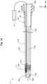
- Fig. 1 is an explanatory diagram illustrating a configuration of a light irradiation device 1 according to a first embodiment.
- the light irradiation device 1 is used by being inserted into a biological lumen, such as the vascular system, lymph gland system, biliary system, urinary tract system, airway system, digestive system, secretory glands, and reproductive organs, and irradiates light from such a lumen of a living body toward living tissue.
- the light irradiation device 1 can be used, for example, in PDT (Photodynamic Therapy) and NIR-PIT (Near-Infrared Photoimmunotherapy).
- PDT Photodynamic Therapy
- NIR-PIT Near-Infrared Photoimmunotherapy
- the following embodiments are illustrated using laser light as an example of light. However, for example, LED light or white light may be used to configure the light irradiation device 1.
- the axis passing through the center of the light irradiation device 1 is represented by the axis O (dot and dash line).
- the axis passing through the center of the light irradiation device 1 and the axis passing through the center of each member (for example, the main body portion 110 and the connector 140) of the light irradiation device 1 will be described as being coincident with the axis O. However, they may be different from each other.
- an X-axis, Y-axis, and Z-axis that are orthogonal to each other are illustrated.
- the X-axis corresponds to the axial direction of the light irradiation device 1 (the insertion direction of the light irradiation device 1).
- the Y-axis corresponds to the height direction of the light irradiation device 1.
- the Z-axis corresponds to the width direction of the light irradiation device 1.
- the left side (the negative X-axis direction) in Fig. 1 is referred to as the "distal end side" of the light irradiation device 1 and each component.
- the right side (the positive X-axis direction) in Fig. 1 is referred to as the "proximal end side" of the light irradiation device 1 and each component.
- the end located on the distal end side is referred to as the "distal end", and the distal end and the vicinity thereof are referred to as the "distal end portion”.
- the end located on the proximal end side is referred to as the "proximal end”, and the proximal end and the vicinity thereof are referred to as the "proximal end portion”.
- the distal end side corresponds to the "distal end side” inserted into the living body
- the proximal end side corresponds to the "proximal end side” operated by the surgeon such as a physician.
- the light irradiation device 1 has a main body portion 110, a distal tip 120, and a connector 140.
- the main body portion 110 is an elongated member (shaft) extending along the axis O.
- the main body portion 110 has a hollow, substantially cylindrical shape with openings at both ends at a distal end portion 110d and a proximal end portion 110p.
- a lumen 110L is provided inside the main body portion 110.
- the lumen 110L functions as a guidewire lumen for inserting a guidewire into the light irradiation device 1 during delivery of the light irradiation device 1.
- the outer diameter, the inner diameter, and the length of the main body portion 110 can be arbitrarily determined.
- the distal tip 120 is a member which is joined to the distal end portion 110d of the main body portion 110, and travels inside the biological lumen ahead of the other members. As shown in Fig. 1 , in order to enable smooth travel of the light irradiation device 1 inside the biological lumen, the distal tip 120 has an outer shape whose diameter is reduced from the proximal end side toward the distal end side. Furthermore, a substantially central portion of the distal tip 120 has a through-hole formed through the distal tip 120 in the axis O direction. The diameter of the through-hole of the distal tip 120 is substantially the same as the diameter of the lumen 110L. An opening 120o of the distal tip 120 is connected to the through-hole, and is used when inserting a guidewire (not illustrated) through the light irradiation device 1. The outer diameter and the length of the distal tip 120 can be arbitrarily determined.
- the connector 140 is a member which is arranged on the proximal end side of the light irradiation device 1, and is gripped by the surgeon.
- the connector 140 includes a connection portion 141 having a substantially cylindrical shape, and a pair of blades 142.
- the proximal end portion 110p of the main body portion 110 is joined to the distal end portion of the connection portion 141, and the blades 142 are joined to the proximal end portion.
- the blades 142 may have an integrated structure with the connector 140.
- the opening 140o of the connector 140 is connected to the lumen 110L via the inside of the connector 140, and is used to withdraw the guidewire that has been inserted into the light irradiation device 1 to outside.
- the outer diameter, the inner diameter, and the length of the connection portion 141, and the shape of the blades 142 can be arbitrarily determined.
- the main body portion 110 of the light irradiation device 1 is further provided with a light conveying portion 150, a light irradiation portion 139, and a marker portion 131.
- the light conveying portion 150 is an optical fiber which is embedded in the thick-walled portion constituting the tube wall of the main body portion 110, and extends along the axis O direction (X-axis direction) from the distal end side to the proximal end side of the main body portion 110.
- the proximal end portion of the light conveying portion 150 is connected via a connector (not illustrated) to a laser light generator 3 that generates laser light having an arbitrary wavelength, either directly in indirectly via another optical fiber.
- the laser light generator 3 functions as a "light source" installed outside the light irradiation device 1.
- the distal end portion of the light conveying portion 150 has the cladding and coating removed from the optical fiber to expose the core.
- Fig. 2 is an explanatory diagram illustrating a cross-sectional configuration taken along line A-Ain Fig. 1 .
- the light irradiation portion 139 is arranged on the distal end portion of the light conveying portion 150, and irradiates the light transmitted by the light conveying portion 150 to outside of the light irradiation device 1.
- the light conveying portion 150 irradiates an emission light LT from the core exposed at the distal end portion of the light conveying portion 150 to outside in one direction from a side surface of the light irradiation device 1 ( Fig. 2 : white-filled arrow). As shown in Fig.
- the light irradiation portion 139 is a resin body covering the distal end of the core of the light conveying portion 150, and is exposed to one portion of the side surface on the distal end side of the main body portion 110.
- the light irradiation portion 139 can be formed, for example, by applying an acrylic ultraviolet-curable resin containing dispersed fine quartz powder, and curing the resin using ultraviolet light.
- the light irradiation portion 139 may be realized in other forms, for example, by a light-reflecting mirror instead of a resin body.
- the light irradiation portion 139 may be formed on one portion of the light conveying portion 150 by applying a known process (such as a process that diagonally cuts the distal end surface, a process that forms a notch, a sandblasting process, or a chemical treatment) to the core exposed at the distal end portion of the light conveying portion 150.
- a known process such as a process that diagonally cuts the distal end surface, a process that forms a notch, a sandblasting process, or a chemical treatment
- the laser light LT generated by the laser light generator 3 is transmitted from the proximal end side to the distal end side of the light conveying portion 150 via the core of the optical fiber, and is irradiated from the core exposed at the distal end portion through the light irradiation portion 139, and then to outside in one direction from a side surface of the light irradiation device 1 ( Fig. 2 : white-filled arrow).
- the marker portion 131 functions as a marking that represents the location of the light irradiation portion 139.
- the illustration for the marker portion 131 is represented as a schematic view rather than a cross-sectional view ( Fig. 1 and 2 : reference numeral 131 displayed as a dashed line).
- the marker portion 131 is a member formed by winding a wire in a spiral shape, whose outer diameter is substantially the same as the outer diameter of the main body portion 110.
- the marker portion 131 is embedded in the thick-walled portion constituting the tube wall of the main body portion 110 on the distal end side of the main body portion 110, and is arranged extending along the thick-walled portion of the main body portion 110 in the axis O direction.
- the light irradiation portion 139 is provided exposed to one portion of the side surface on the distal end side of the main body portion 110, a portion of the marker portion 131 on the distal end side is embedded in the resin body of the light irradiation portion 139, or is arranged on the surface of the resin body. Furthermore, as shown in Fig.
- the marker portion 131 is arranged so that the center of the emission light LT from the light irradiation portion 139 is located ⁇ degrees in a right-handed (clockwise) rotation in the circumferential direction from a start-of-winding portion 131P located on the distal end side.
- ⁇ 90 degrees.
- the marker portion 131 may be disposed in a different location to the light irradiation portion 139 in the axis O direction (X-axis direction).
- the start-of-winding portion 131P may be located on the proximal end side of the proximal end portion of the light irradiation portion 139.
- the outer diameter of the marker portion 131 can be arbitrarily determined, and may be, for example, larger than the outer diameter of the main body portion 110, an arbitrary size which is at least as large as the inner diameter of the main body portion 110 but smaller than the outer diameter, or smaller than the inner diameter of the main body portion 110 (that is to say, the diameter of the lumen 110L).
- the marker portion 131 can be formed of a resin material or a metallic material having radiopacity.
- a resin material when a resin material is used, it can be formed by mixing a radiopaque material such as bismuth trioxide, tungsten, or barium sulfate with a polyamide resin, a polyolefin resin, a polyester resin, a polyurethane resin, a silicon resin, a fluorine resin, or the like.
- a metallic material it can be formed of gold, platinum, tungsten, or an alloy containing these elements (such as a platinum-nickel alloy), which are radiopaque materials.
- the main body portion 110 preferably has antithrombogenic properties, flexibility, and biocompatibility, and can be formed of a resin material or a metallic material.
- a resin material for example, a polyamide resin, a polyolefin resin, a polyester resin, a polyurethane resin, a silicon resin, or a fluororesin can be used.
- the metallic material for example, stainless steel such as SUS304, a nickel-titanium alloy, a cobalt-chromium alloy, or tungsten steel can be used.
- the main body portion 110 can also be a bonded structure combining a plurality of the materials mentioned above.
- the distal tip 120 preferably has flexibility and can be formed of a resin material such as polyurethane, a polyurethane elastomer, or the like.
- the connector 240 can be formed of a resin material such as polyamide, polypropylene, polycarbonate, polyacetal, polyethersulfone, or the like.
- a method of using of the light irradiation device 1 will be described. First, the surgeon inserts a guidewire into the biological lumen. Next, the surgeon inserts the proximal end side of the guidewire through the opening 120o of the distal tip 120 of the light irradiation device 1 shown in Fig. 1 and into the lumen 110L, and pulls it out through the opening 140o of the connector 140. Then, the surgeon pushes the light irradiation device 1 into the biological lumen along the guidewire, and delivers the light irradiation portion 139 of the light irradiation device 1 to the target site of the light irradiation (for example, near the cancer cells in the case of NIR-PIT).
- the target site of the light irradiation for example, near the cancer cells in the case of NIR-PIT.
- the main body portion 110 of the light irradiation device 1 has an elongated tube shape having the lumen 110L (inner cavity). Therefore, by inserting a guidewire through the lumen 110L of the main body portion 110, the light irradiation device 1 can be easily delivered to the target site in the biological lumen. Note that, during delivery, the surgeon can position the insertion direction (X-axis direction) location of the light irradiation device 1 in the biological lumen while confirming the location of the marker portion 131 in an X-ray image.
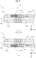
- Fig. 3 is an explanatory diagram illustrating the light irradiation device 1 while in use.
- the upper part of Fig. 3 shows the light irradiation device 1 before rotation, and the lower part of Fig. 3 shows the light irradiation device 1 after rotation.
- the guidewire inserted into the lumen 110L is not shown.
- the surgeon After positioning the light irradiation device 1 in the insertion direction (X-axis direction), the surgeon confirms the shape of the marker portion 131 in an X-ray image to direct the emission direction of the emission light LT toward the direction of the target site of light irradiation in the biological lumen.
- the surgeon can change the emission direction of the emission light LT by rotating the light irradiation device 1 in the circumferential direction (YZ-axis direction) while maintaining the location of the light irradiation device 1 in the X-axis direction.
- the surgeon can grasp the direction of the emission light LT from the light irradiation portion 139 by the shape of the marker portion 131 in an X-ray image. In this way, the laser light LT transmitted through the light conveying portion 150 and emitted from the light irradiation portion 139 can be emitted toward the external biological tissue.
- the light irradiation device 1 of the first embodiment is provided with a radiopaque marker portion 131 provided on the distal end side of the main body portion 110.
- the surgeon is capable of determining the insertion direction (X-axis direction) location of the light irradiation site (light irradiation portion 139) in the biological lumen by confirming the location of the marker portion 131 inside the body through X-ray imaging.
- the marker portion 131 is configured so that the circumferential direction (YZ-axis direction) location of the light irradiation portion 139 can be recognized by the shape of the marker portion 131 when viewed from an arbitrary direction outside the body. Therefore, the surgeon can easily position the light irradiation portion 139 in the biological lumen in the circumferential direction in addition to the insertion direction.
- the light irradiation device 1 of the first embodiment it is possible to selectively irradiate a specific location in a biological lumen with light, which enables, for example, the selective irradiation of cancer cells with light in NIR-PIT.
- the light irradiation portion 139 which irradiates light to outside, is provided on one portion of the side surface on the distal end side of the main body portion 110.
- the area of the biological tissue which is irradiated with light can be limited. This can contribute to the suppression of biological tissue damage caused by unnecessary light irradiation of biological tissue.
- the marker portion 131 has a spiral shape extending in the axis O direction (X-axis direction) of the light irradiation device 1.
- Fig. 3 by grasping the association between the winding direction of the spiral ( Fig. 2 : right-handed rotation in the circumferential direction) and the location of the light irradiation portion 139 ( Fig. 2 : a location ⁇ degrees from the start-of-winding portion 131P) in advance, the surgeon is capable of easily grasping the irradiation direction of the emission light LT from the light irradiation portion 139 even in a state where the light irradiation device 1 has been inserted in a biological lumen. Therefore, the positioning of the light irradiation portion 139 in the circumferential direction (YZ-axis direction) can be performed more easily.
- the light irradiation device 1 can be made thinner in diameter compared with a case where the marker portion 131 is provided protruding from the main body portion 110, and damage to the biological tissue caused by the protruding portion can be suppressed.
- the light irradiation device 1 further includes the light conveying portion 150, which is connected to the external laser light generator 3 (light source) and transmits the light from the laser light generator 3 to the light irradiation portion 139. Consequently, compared with a configuration in which the light source is built into the light irradiation device 1, the light irradiation device 1 can be made smaller.
- the light conveying portion 150 is embedded in the thick-walled portion of the main body portion 110, the usability of the light irradiation device 1 can be improved compared with a configuration in which the light conveying portion 150 is not embedded.
- Fig. 4 is an explanatory diagram illustrating a configuration of a light irradiation device 1A according to a second embodiment.
- the light irradiation device 1A of the second embodiment includes, in addition to the configuration described in the first embodiment, a distal end side marker portion 132 and a proximal end side marker portion 133.
- the distal end side marker portion 132 is provided on the distal end side of the marker portion 131, and functions as a marking that represents the location of the distal end portion of the marker portion 131.
- the proximal end side marker portion 133 is provided on the proximal end side of the marker portion 131, and functions as a marking that represents the location of the proximal end of the marker portion 131.
- Fig. 4 is an explanatory diagram illustrating a configuration of a light irradiation device 1A according to a second embodiment.
- the light irradiation device 1A of the second embodiment includes, in addition to the configuration described in the first embodiment
- the distal end side marker portion 132 is provided in close proximity to the distal end portion of the light irradiation portion 139, and the location of the distal end side marker portion 132 and the location of the marker portion 131 do not overlap in the axis O direction (X-axis direction).
- the proximal end side marker portion 133 is provided in close proximity to the proximal end portion of the marker portion 131, and the location of the proximal end side marker portion 133 and the location of the marker portion 131 do not overlap in the axis O direction.
- the locations of the distal end side marker portion 132 and the proximal end side marker portion 133 may overlap with the location of the marker portion 131 in the axis O direction.
- the distal end side marker portion 132 and the proximal end side marker portion 133 are both hollow, substantially cylindrically-shaped members.
- the distal end side marker portion 132 and the proximal end side marker portion 133 are each arranged in a recess formed on the outer surface of the main body portion 110, and are joined to the outer surface of the main body portion 110.
- the distal end side marker portion 132 and the proximal end side marker portion 133 are each embedded in the outer surface of the main body portion 110 so as to surround the main body portion 110 in the circumferential direction.
- the distal end side marker portion 132 and the proximal end side marker portion 133 may also be provided protruding from the outer surface of the main body portion 110 by being joined to the outer surface of a main body portion 110 not having a recess.
- the distal end side marker portion 132 and the proximal end side marker portion 133 can be formed of a resin material or a metallic material having radiopacity.
- the materials of the distal end side marker portion 132 and the proximal end side marker portion 133 may be the same or different from the marker portion 131.
- the light irradiation device 1A may be provided with another marker as a marking that represents the location of the marker portion 131.
- An effect similar to that of the first embodiment described above can also be exhibited by the light irradiation device 1A according to the second embodiment described above.
- the light irradiation device 1A of the second embodiment is further provided with the radiopaque distal end side marker portion 132 provided on the distal end side of the marker portion 131.
- the surgeon is capable of easily grasping the location of the distal end side of the marker portion 131 in the biological lumen. Therefore, the positioning of the light irradiation portion 139 in the insertion direction can be performed more easily.
- the radiopaque proximal end side marker portion 133 provided on the proximal end side of the marker portion 131 is provided.
- the surgeon is capable of easily grasping the location of the proximal end side of the marker portion 131 in the biological lumen. Therefore, the positioning of the light irradiation portion 139 in the insertion direction can be performed more easily.
- Fig. 5 is an explanatory diagram illustrating a configuration of a light irradiation device 1B according to a third embodiment.
- the light irradiation device 1B of the third embodiment includes the distal end side marker portion 132 of the configuration described in the second embodiment, but does not include the proximal end side marker portion 133.
- the number of other markers provided on the light irradiation device 1B may be one, or may be three or more.
- An effect similar to that of the first embodiment described above can also be exhibited by the light irradiation device 1B according to the third embodiment described above.
- the light irradiation device 1B of the third embodiment is further provided with the radiopaque distal end side marker portion 132 provided on the distal end side of the marker portion 131.
- the surgeon is capable of easily grasping the location of the distal end side of the marker portion 131 in the biological lumen. Therefore, the positioning of the light irradiation portion 139 in the insertion direction can be performed more easily.
- Fig. 6 and Fig. 7 are explanatory diagrams illustrating a configuration of a light irradiation device 1C according to a fourth embodiment.
- Fig. 7(A) shows an example of the configuration of the light irradiation device 1C viewed from the positive Y-axis direction.
- Fig. 7(B) shows another example of the configuration of the light irradiation device 1C viewed from the positive Y-axis direction.
- the light irradiation device 1C includes a distal end side marker portion 132C instead of the distal end side marker portion 132 described in the second embodiment, and includes a proximal end side marker portion 133C instead of the proximal end side marker portion 133.
- the distal end side marker portion 132 and the proximal end side marker portion 133 are each provided on one portion of the circumferential direction (YZ-axis direction) of the light irradiation device 1C.
- the distal end side marker portion 132C is provided along the side of the light irradiation portion 139 on the distal end side, and in substantially the same area as the light irradiation portion 139.
- the proximal end side marker portion 133C is provided in a location leaving a predetermined spacing with the side of the light irradiation portion 139 on the proximal end side, and in substantially the same area as the light irradiation portion 139.
- the distal end side marker portion 132C and the proximal end side marker portion 133C are provided so as to surround the light irradiation portion 139.
- the distal end side marker portion 132C and the proximal end side marker portion 133C can be provided only in one portion of the circumferential direction as shown in the drawing.
- An effect similar to that of the first and second embodiments described above can also be exhibited by the light irradiation device 1C according to the fourth embodiment described above.
- the distinction with the spiral-shaped marker portion 131 can be made more easily, and the production cost of the light irradiation device 1C can be reduced.
- Fig. 8 is an explanatory diagram illustrating a configuration of a light irradiation device 1D according to a fifth embodiment.
- the light irradiation device 1D of the fifth embodiment includes, in the configuration described in the first embodiment, a marker portion 131D instead of the marker portion 131.
- the marker portion 131D includes a plurality of members made by bending wires into a semicircular arc shape.
- Each of the members is arranged so as to extend in the thick-walled portion of the main body portion 110 in the axis O direction (X-axis direction) by being embedded at substantially equal intervals in the axis O direction (X-axis direction) on the distal end side of the main body portion 110, and in the thick-walled portion constituting the tube wall of the main body portion 110 and the light irradiation portion 139.
- the marker portion 131D can be formed of a resin material or a metallic material having radiopacity. The material of the marker portion 131D may be the same or different from the marker portion 131.
- the marker portion 131D may be configured by a plurality of members made by bending wires into a semicircular arc shape.
- each member is not limited to a semicircular arc shape, and a circular arc of an arbitrary angle (for example, a letter-C shape), a shape that imitates one portion of a polygon, and the like can be adopted.
- An effect similar to that of the first embodiment described above can also be exhibited by the light irradiation device 1D according to the fifth embodiment described above.
- Fig. 9 is an explanatory diagram illustrating a configuration of a light irradiation device 1E according to a sixth embodiment.
- the light irradiation device 1E of the sixth embodiment includes, in the configuration described in the first embodiment, a marker portion 131E instead of the marker portion 131 .
- the marker portion 131E includes a single member made by bending a wire into a semicircular arc shape. This member is embedded on the distal end side of the main body portion 110, and in the thick-walled portion constituting the tube wall of the main body portion 110 and the light irradiation portion 139.
- the marker portion 131E can be formed of a resin material or a metallic material having radiopacity.
- the material of the marker portion 131E may be the same or different from the marker portion 131. As a result of including such a marker portion 131E, in the light irradiation device 1E, it is possible to recognize the location of the light irradiation portion 139 in the circumferential direction (YZ-axis direction) by the shape of the marker portion 131E when viewed from an arbitrary direction outside the body.
- the marker portion 131E may be configured by a single member made by bending a wire into a semicircular arc shape.
- each member is not limited to a semicircular arc shape, and a circular arc of an arbitrary angle (for example, a letter-C shape), a shape that imitates one portion of a polygon, and the like can be adopted.
- An effect similar to that of the first embodiment described above can also be exhibited by the light irradiation device 1E according to the sixth embodiment described above.
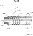
- Fig. 10 is an explanatory diagram illustrating a configuration of a light irradiation device 1F according to a seventh embodiment.
- the light irradiation device 1F of the seventh embodiment includes, in the configuration described in the first embodiment, a light irradiation portion 139F instead of the light irradiation portion 139, and a distal tip 120F instead of the distal tip 120.
- the light irradiation portion 139F is provided exposed on one portion of a side surface of the distal end portion 110D of the main body portion 110.
- the distal tip 120F is joined to the distal end portion of the light irradiation portion 139F, and the distal end portion 110d of the main body portion 110.
- the distal tip 120F is formed of a resin material or a metallic material having radiopacity, and functions as a marking representing the location of the distal end portion of the marker portion 131.
- the material of the distal tip 120F may be the same or different from the marker portion 131.
- the distal tip 120F may function as the distal end side marker portion 132 (second embodiment) by forming the distal tip 120F with a resin material or a metallic material having radiopacity.
- An effect similar to that of the first, second and third embodiments described above can also be exhibited by the light irradiation device 1F according to the seventh embodiment described above.
- the distal tip 120F can be made to function as the distal end side marker portion 132. Therefore, the production process of the light irradiation device 1F can be simplified compared with a case where a separate distal end side marker portion 132 is provided.
- Fig. 11 is an explanatory diagram illustrating a configuration of a light irradiation device 1G according to an eighth embodiment.
- the light irradiation device 1G of the eighth embodiment includes, in the configuration described in the first embodiment, a main body portion 110G instead of the main body portion 110, and a distal tip 120G instead of the distal tip 120.
- the inside of the main body portion 110G is not provided with the lumen 110L (first embodiment).
- a through-hole is not formed in the distal tip 120G.
- various configurations can be adopted for the light irradiation device 1G.
- a configuration is possible in which a guidewire lumen as illustrated above is not provided.
- An effect similar to that of the first embodiment described above can also be exhibited by the light irradiation device 1G according to the eighth embodiment described above.
- Fig. 12 is an explanatory diagram illustrating a configuration of a light irradiation system according to a ninth embodiment.
- the light irradiation system of the ninth embodiment includes, in addition to the light irradiation device 1 described in the first embodiment, a catheter 2 for inserting the light irradiation device 1.
- the catheter 2 has an elongated tube shape, and includes a main body portion 210, a distal tip 220, and a connector 240.
- the main body portion 210 is an elongated member extending along the axis O, and has a hollow, substantially cylindrical shape with openings at both ends at a distal end portion 210d and a proximal end portion 210d.
- a lumen 210L is provided inside the main body portion 210.
- the diameter phi 2 of the lumen 210L is larger than the outer diameter phi 4 of the light irradiation device 1 (phi 2 > phi 4).
- the lumen 210L functions as a guidewire lumen for inserting a guidewire into the catheter 2 during delivery of the catheter 2. After delivery of the catheter 2, the lumen 210L functions as a device lumen for inserting the light irradiation device 1 into the catheter 2.
- the distal tip 220 is a member which is joined to the distal end portion 210d of the main body portion 210, and travels inside the biological lumen ahead of the other members.
- the distal tip 220 has an outer shape whose diameter is reduced from the proximal end side toward the distal end side.
- a substantially central portion of the distal tip 220 has a through-hole formed through the distal tip 220 in the axis O direction.
- the diameter phi 1 of the through-hole is smaller than the diameter phi 2 of the lumen 210L of the main body portion 210.
- a step is formed due to the protrusion of the inner surface 220i of the distal tip 220.
- the opening 220o of the distal tip 220 is connected to the through-hole, and is used when inserting a guidewire (not illustrated) through the catheter 2.
- the outer diameter and the length of the distal tip 220 can be arbitrarily determined.
- the connector 240 is a member which is arranged on the proximal end side of the catheter 2, and is gripped by the surgeon.
- the connector 240 includes a connection portion 241 having a substantially cylindrical shape, and a pair of blade portions 242.
- the proximal end portion 210d of the main body portion 210 is joined to the distal end portion of the connection portion 241, and the blade portions 242 are joined with the proximal end portion.
- the blades 242 may have a structure in which they are integrated with the connector 240.
- the opening 240o of the connector 240 is connected to the lumen 210L via the inside of the connector 240, and is used when inserting the light irradiation device 1 into the catheter 2.
- the outer diameter, the inner diameter, and the length of the connection portion 241, and the shape of the blade portions 242 can be arbitrarily determined.
- the main body portion 210 of the catheter 2 is further provided with a light transmitting portion 239, a distal end side marker portion 231, and a proximal end side marker portion 232.
- the light transmitting portion 239 transmits the light inside the main body portion 210 to outside.
- the light transmitting portion 239 is member having a hollow, substantially cylindrical shape. It has substantially the same outer diameter as the outer diameter of the main body portion 210, and substantially the same inner diameter as the diameter phi 2 of the lumen 210L of the main body portion 210.
- the light transmitting portion 239 is provided on the entire circumferential direction (YZ-axis direction), and transmits the light inside the main body portion 210 to outside in the entire circumferential direction.
- the light transmitting portion 239 is joined to the main body portion 210 on both the proximal end side and the distal end side.
- the light transmitting portion 239 can be formed from a transparent resin material having light transmitting properties, such as an acrylic resin, polyethylene terephthalate, polyvinyl chloride, and the like.
- the distal end side marker portion 231 and the proximal end side marker portion 232 function as markings representing the location of the light transmitting portion 239.
- the distal end side marker portion 231 is provided in close proximity to the distal end portion of the light transmitting portion 239, and functions as a marking that represents the location of the distal end portion of the light transmitting portion 239.
- the proximal end side marker portion 232 is provided in close proximity to the proximal end portion of the light transmitting portion 239, and functions as a marking that represents the location of the proximal end portion of the light transmitting portion 239.
- the distal end side marker portion 231 and the proximal end side marker portion 232 are both hollow, substantially cylindrically-shaped members.
- the distal end side marker portion 231 and the proximal end side marker portion 232 are each arranged in a recess formed on the outer surface of the main body portion 210, and are joined to the outer surface of the main body portion 210.
- the distal end side marker portion 231 and the proximal end side marker portion 232 are each embedded in the outer surface of the main body portion 210 so as to surround the main body portion 210 in the circumferential direction.
- the distal end side marker portion 231 and the proximal end side marker portion 232 may also be provided protruding from the outer surface of the main body portion 210 by being joined to the outer surface of the main body portion 210 not having a recess.
- the distal end side marker portion 231 and the proximal end side marker portion 232 can be formed of a resin material or a metallic material having radiopacity.
- the main body portion 110 of the light irradiation device 1 the main body portion 210 can be formed of a resin material or a metallic material.
- the distal tip 120 of the light irradiation device 1 the distal tip 220 can be formed of a resin material having flexibility.
- the connector 240 can be formed of a resin material.
- the surgeon inserts a guidewire into the biological lumen.
- the surgeon inserts the proximal end side of the guidewire through the opening 220o of the distal tip 220 of the catheter 2 shown in Fig. 12 and into the lumen 210L, and causes it to protrude from the opening 240o of the connector 240.
- the surgeon pushes the catheter 2 into the biological lumen along the guidewire, and delivers the light transmitting portion 239 of the catheter 2 to the target site of the light irradiation (for example, near the cancer cells in the case of NIR-PIT).
- the surgeon can easily deliver the catheter 2 to the target site in the biological lumen.
- the surgeon can position the catheter 2 in the biological lumen while confirming the locations of the distal end side marker portion 231 and the proximal end side marker portion 232 arranged in close proximity to the light transmitting portion 239 in an X-ray image. Then, the surgeon then removes the guidewire from the catheter 2.
- the surgeon inserts the light irradiation device 1 through the opening 240o of the connector 240 of the catheter 2.
- the surgeon pushes the light irradiation device 1 along the lumen 210L of the catheter 2 toward the distal end side of the catheter 2.
- the distal end surface 120e of the light irradiation device 1 collides with the inner surface 220i of the distal tip 220 when the light irradiation device 1 is inserted into the catheter 2, and the light irradiation device 1 can be prevented from going through to the distal end side.
- the surgeon positions the light irradiation portion 139 and the light transmitting portion 239 in the axis O direction (X-axis direction) by confirming the positional relationship between the marker portion 131 of the light irradiation device 1 and the distal end side marker portion 231 and the proximal end side marker portion 232 of the catheter 2 in an X-ray image.
- the surgeon positions the light irradiation portion 139 in the circumferential direction (in the YZ-axis direction) by the method described in the first embodiment, and irradiates the target site in the biological lumen with light.
- the guidewire is inserted into the lumen 110L of the light irradiation device 1, and the light irradiation device 1 may be delivered in a state where the light irradiation device 1 inserted into the catheter 2.
- the light irradiation device 1 may be used in combination with the catheter 2 provided with the light transmitting portion 239 that transmits light from the light irradiation device 1 to outside.
- the configuration of the catheter 2 described above is only an example, and various modifications are possible. An effect similar to that of the first embodiment described above can also be exhibited by the light irradiation system according to the ninth embodiment described above.
- the range of procedures can be expanded by using the light irradiation device 1 in combination with the catheter 2.
- Fig. 13 is an explanatory diagram illustrating a configuration of a light irradiation system according to a tenth embodiment.
- the light irradiation system of the tenth embodiment includes a light irradiation device 1H instead of the light irradiation device 1 described in the first embodiment, and a catheter 2H instead of the catheter 2 described in the ninth embodiment.
- the light irradiation device 1H has a distal end side marker portion 261 and a proximal end side marker portion 262 instead of the marker portion 131, and a light irradiation portion 139H instead of the light irradiation portion 139.
- the distal end side marker portion 261 is provided in close proximity to the distal end portion of the light irradiation portion 139, and functions as a marking that represents the location of the distal end portion of the light irradiation portion 139.
- the proximal end side marker portion 262 is provided in close proximity to the proximal end portion of the light irradiation portion 139, and functions as a marking that represents the location of the proximal end portion of the light irradiation portion 139.
- the configurations of the distal end side marker portion 261 and the proximal end side marker portion 262 are the same as those of the distal end side marker portion 231 and the proximal end side marker portion 232 of the catheter 2 described in the ninth embodiment. At least one of the distal end side marker portion 261 and the proximal end side marker portion 262 may be omitted.
- the light irradiation portion 139H is a solid, substantially cylindrical member having substantially the same diameter as the outer diameter of the main body portion 110.
- the light irradiation portion 139H is joined to the main body portion 110 on the proximal end side and the distal end side. Furthermore, the surface on the proximal end side of the light irradiation portion 139H covers the distal end of the exposed core of the light conveying portion 150.
- the catheter 2H further includes a marker portion 161, and a light transmitting portion 239H instead of the light transmitting portion 239.
- the marker portion 161 functions as a mark that represents the location of the light transmitting portion 239.
- the configuration of the marker portion 161 is the same as that of the marker portion 131 of the light irradiation device 1 described in the first embodiment.
- the light transmitting portion 239H is an arc-shaped plate member and is joined to the body portion 210 by being fitted to one portion of the main body portion 210. As a result, in the catheter 2H, the light transmitting portion 239H is provided in one portion of the circumferential direction, and transmits the light inside the main body portion 110 to outside in one portion of the circumferential direction.
- the surgeon uses the catheter 2H to position the insertion direction (X-axis direction) and to position the circumferential direction (YZ-axis direction) in advance. Then, the surgeon inserts the light irradiation device 1H into the catheter 2H, and positions the light irradiation device 1H in the insertion direction (X-axis direction) inside the catheter 2H. Then, the laser light LT is emitted.
- the catheter 2H may be provided with a marker portion 161 that enables, due to the shape when viewed from an arbitrary direction, the circumferential direction location of the light irradiation portion 139 to be recognized after being inserted into the catheter 2H.
- the light irradiation portion 139H and the light transmitting portion 239H can be provided in an arbitrary area in the circumferential direction, and as shown in Fig. 13 , the light irradiation system may be configured by combining a light transmitting portion 239H that transmits light to a portion of the circumferential direction, and a light irradiation portion 139H that irradiates light to the entire circumference. Moreover, a light irradiation portion 139 ( Fig. 12 ) that irradiates light to a portion of the circumferential direction, and a light transmitting portion 239H ( Fig. 13 ) that transmits light to a portion of the circumferential direction may be combined.
- a light irradiation portion 139H ( Fig. 13 ) that irradiates light to the entire circumference
- a light transmitting portion 239 Fig. 12
- An effect similar to that of the first embodiment described above can also be exhibited by the light irradiation system according to the tenth embodiment described above.
- Fig. 14 is an explanatory diagram illustrating a configuration of a light irradiation device 1J according to an eleventh embodiment.
- the light irradiation device 1J is provided with a marker portion 131J instead of the marker portion 131 of the first embodiment.
- the marker portion 131J is composed of radiopaque granular material arranged in a spiral shape. In this way, the marker portion 131J can be arbitrarily changed to the extent that the circumferential direction (YZ-axis direction) location of the light irradiation portion 139 can be recognized by the shape of the marker portion 131J when viewed from an arbitrary direction.
- the light irradiation device 1J may be made of a granular body instead of a wire, or it may be made by mixing a powder having radiopacity with the resin material of the main body portion 110.
- An effect similar to that of the first embodiment described above can also be exhibited by the light irradiation device 1J according to the eleventh embodiment described above.
- the configuration of the light irradiation devices 1, 1A to 1G, and the catheter 2 have been described.
- the configuration of the light irradiation device 1 and the catheter 2 can be modified in various ways.
- a reinforcing layer composed of a braided body or a coil body may be embedded in the main body portion 110 of the light irradiation device 1 and the main body portion 210 of the catheter 2.
- a coating consisting of a hydrophilic or hydrophobic resin may be applied to the outer surface of the light irradiation device 1 or to the outer surface of the catheter 2.
- an antithrombotic material such as heparin may be coated on the outer surface of the light irradiation device 1 or on the outer surface of the catheter 2. In this way, it is possible to suppress a decrease in laser output due to adhesion of a blood clot to the inner or outer surface of the catheter 2 or the outer surface of the light irradiation device 1 caused by irradiation of the emission light (laser light) LT.
- the catheter 2 may be provided with an expansion portion that can be expanded in the radial direction (YZ direction).
- a balloon made of a flexible thin film or a mesh body in which wires have been processed into a mesh shape can be used as the expansion portion.
- the expansion portion can be provided in the main body portion 210 on at least one of the distal end side of the light transmitting portion 239 and the proximal end side of the light transmitting portion 239. In this way, after positioning the catheter 2 in the biological lumen, the catheter 2 can be fixed in the biological lumen by expanding the expansion portion.
- a balloon is used as the expansion portion, the blood flow at the light-irradiated position can be blocked. Therefore, light can be prevented from being blocked by the blood flow.
- the light irradiation device 1 may be configured as a multi-lumen catheter having a separate lumen that is different from the lumen 110L through which the light conveying portion 150 is inserted.
- the catheter 2 may be configured as a multi-lumen catheter having a plurality of lumens that are different from the lumen 210L.
- an inner surface 220i of the distal tip 220 of the catheter 2 and an outer surface 120e of the distal tip 120 of the light irradiation device 1 may be made of a magnetic body, and configured to attract each other. In this way, a state where the light irradiation device 1 is inserted into the catheter 2, and the distal tip 120 is pressed against the distal tip 220 can be easily maintained.
- At least one of the light irradiation device 1 and the catheter 2 may further include a temperature sensor.
- the temperature sensor can be configured by, for example, a pair of thermocouples embedded in the thick-walled portion of the main body portion 110 or the main body portion 210, and measure the temperature of the biological tissue in close proximity to the light irradiation portion 139 or the light transmitting portion 239. In this way, temperature changes of the biological tissue caused by light irradiation can be observed in real time, which can contribute to the suppression of blood coagulation and damage to biological tissue caused by light irradiation.
- the configuration of the marker portions 131, 131D, 131E, and 131J have been described. Furthermore, various changes can be made to the configuration of the marker portions 131, 131D, 131E, and 131J to the extent that the circumferential direction location of the light irradiation portion 139 can be recognized by the shape of the marker portion 131 when viewed from an arbitrary direction.
- the marker portion 131 may be configured to have a wave shape extending along the axis O direction, or a zigzag shape extending along the axis O direction on the surface of the main body portion 110.
- the configuration of the light irradiation portion 139 and the light transmitting portion 239 can be modified in various ways. For example, by configuring the light irradiation portion 139 with a radiopaque material, the light irradiation portion 139 and the distal end side marker portion 132 may be integrally configured. Similarly, by configuring the light transmitting portion 239 with a radiopaque material, the light transmitting portion 239, the distal end side marker portion 231 and the proximal end side marker portion 232 may be integrally configured.
- At least one of the light irradiation portion 139 and the light transmitting portion 239 may be formed as a notch (a through-hole communicating the lumen and outside) formed in the main body portion 110 or the main body portion 210. In this way, the light irradiation portion 139 and the light transmitting portion 239 can be easily configured.
- the distal end surface of the light conveying portion 150 may be diagonally cut, and the distal end surface may be configured as the light irradiation portion 139.
- a light-reflecting mirror installed at an angle with respect to a cut surface of the light conveying portion 150 (a cut surface provided perpendicular to the axis O direction) may be used as the light irradiation portion 139.
- the light conveying portion 150 may be joined to the outer surface of the main body portion 210 without being inserted into the main body portion 210.
- the light transmitting portion 239 may be formed by reducing the thickness of one portion of the main body portion 210.
- the axis O direction (X-axis direction) area in which the light transmitting portion 239 is provided, and the circumferential direction (YZ-axis direction) area in which the light transmitting portion 239 is provided may be arbitrarily changed, and may be longer or shorter than the length illustrated in Fig. 12 .
- the catheter 2 may further include a separate marker portion arranged on the distal end side of the light transmitting portion 239.
- the configurations of the light irradiation devices 1, 1A to 1J, and the catheters 2 and 2H of the first to tenth embodiments, and the configurations of the light irradiation devices 1, 1A to 1J, and the catheters 2 and 2H of modification examples 1 and 2 may be combined as appropriate.
- the light irradiation device 1G described in the eighth embodiment ( Fig. 11 ) at least one of the marker portions 131, 131D and 131E, the distal end side marker portions 132 and 132C, the proximal end side marker portions 133 and 133C, and the distal tip 120F described in the second to seventh embodiments may be provided.
- the light irradiation system described in the ninth and tenth embodiments may include the light irradiation devices 1A to 1J described in the second to eighth and eleventh embodiments.
Landscapes
- Health & Medical Sciences (AREA)
- Biomedical Technology (AREA)
- Engineering & Computer Science (AREA)
- Life Sciences & Earth Sciences (AREA)
- Nuclear Medicine, Radiotherapy & Molecular Imaging (AREA)
- Animal Behavior & Ethology (AREA)
- Veterinary Medicine (AREA)
- Public Health (AREA)
- General Health & Medical Sciences (AREA)
- Pathology (AREA)
- Radiology & Medical Imaging (AREA)
- Physics & Mathematics (AREA)
- Surgery (AREA)
- Otolaryngology (AREA)
- Molecular Biology (AREA)
- Medical Informatics (AREA)
- Heart & Thoracic Surgery (AREA)
- Electromagnetism (AREA)
- Optics & Photonics (AREA)
- Biophysics (AREA)
- Radiation-Therapy Devices (AREA)
- Media Introduction/Drainage Providing Device (AREA)
Abstract
Description
- The disclosed embodiments relate to a light irradiation device and a light irradiation system.
- In cancer treatment, surgical, radiological, and pharmacological (chemical) techniques are used alone or in combination with each other, and these techniques have each experienced development in recent years. However, there are many types of cancer for which satisfactory treatment techniques have not yet been found, and there is an expectation that such treatment techniques will be further developed. A technique referred to as PDT (Photodynamic Therapy) is known as a cancer treatment technique. In PDT, a light-sensitive substance is administered intravenously. Then, light irradiation generates a reactive oxygen species in the cancer cells and kills the cancer cells (for example, see Non-Patent Literature 1). However, PDT has not been widely used as a therapeutic technique due to the low accumulation selectivity of light-sensitive substances within cancer cells, and the significant side effects caused by uptake by normal cells.
- Further, NIR-PIT (Near-Infrared Photoimmunotherapy) is a treatment technique that has been attracting attention in recent years. NIR-PIT uses a complex in which two compounds, namely an antibody against a specific antigen of the cancer cells and a photosensitive substance (such as IRDye 700DX), are bonded to each other. When this complex is administered intravenously, it selectively accumulates in the cancer cells in the body. Then, by irradiating light of an excitation wavelength of the photosensitive substance in the complex (for example, 690 nm), the complex is activated and exhibits anticancer activity (for example, see Patent Literature 1). NIR-PIT can reduce side effects compared to PDT due to the accumulation selectivity of the antibody toward the cancer, and localized light irradiation. Moreover, because NIR-PIT involves light irradiation in a near-infrared region such as 690 nm (NIR irradiation), effects of the NIR irradiation on the immune system are also expected (for example, see Non-Patent Literature 2).
- The predetermined wavelength region illustrated above that includes 690 nm is also referred to as a biological spectroscopic window. This is a wavelength region in which the absorption of light by biological components is lower than in other wavelength regions. However, there is a problem that because the penetration of light is insufficient when the light is irradiated from surface of the body, it cannot be applied to cancers deep inside the body. Therefore, in recent years, NIR-PIT, in which light irradiation is performed from a location close to the cancer cells rather than from the body surface, is being studied (for example, see Non-Patent Literature 3). For example,
Patent Literature 2 andPatent Literature 3 disclose devices that can be used in the PDT and NIR-PIT techniques described above. The devices described inPatent Literature 2 andPatent Literature 3 are both used by being inserted into a blood vessel, and are capable of irradiating light deep inside the body. -
- Patent Literature 1:
Japanese Unexamined Patent Application Publication (Translation of PCT Application) No. 2014-523907 - Patent Literature 2:
Japanese Unexamined Patent Application Publication No. 2018-867 - Patent Literature 3:
Japanese Unexamined Patent Application Publication (Translation of PCT Application) No. 2007-528752 -
- Non-Patent Literature 1: Makoto Mitsunaga, Mikako Ogawa, Nobuyuki Kosaka Lauren T. Rosenblum, Peter L. Choyke, and Hisataka Kobayashi, Cancer Cell-Selective In Vivo Near Infrared Photoimmunotherapy Targeting Specific Membrane Molecules, Nature Medicine 2012 17(12):, p.1685-1691
- Non-Patent Literature 2: Kazuhide Sato, Noriko Sato, Biying Xu, Yuko Nakamura, Tadanobu Nagaya, Peter L. Choyke, Yoshinori Hasegawa, and Hisataka Kobayashi, Spatially selective depletion of tumor-associated regulatory T cells with near-infrared photoimmunotherapy, Science Translational Medicine 2016 Vol. 8 Issue 352, ra110
- Non-Patent Literature 3: Shuhei Okuyama, Tadanobu Nagaya, Kazuhide Sato, Fusa Ogata, Yasuhiro Maruoka, Peter L. Choyke, and Hisataka Kobayashi, Interstitial near-infrared photoimmunotherapy: effective treatment areas and light doses needed for use with fiber optic diffusers, Oncotarget 2018 Feb 16; 9(13):, p.11159-11169
- Here, as described above, in PDT and NIR-PIT, cancer cells are killed by irradiating cancer cells which have accumulated the complex with light of the excitation wavelength of the photosensitive substance within the complex. On the other hand, in order to reduce the risk of cell damage, it is preferable to avoid light irradiation with respect to normal cells that are not cancer cells. In this respect, in the techniques described in
Patent Literature 2 andPatent Literature 3, it is difficult to position the light irradiation site inside the blood vessel. Therefore, it is not possible to selectively irradiate the area where the cancer cells exist. - Such issues are common not only to PDT and NIR-PIT, but to all devices used in examinations or treatments that include the process of light irradiation inside the body. Furthermore, such issues are not limited to devices inserted into a blood vessel, and are common to all devices inserted into a biological lumen, such as the vascular system, lymph gland system, biliary system, urinary tract system, airway system, digestive system, secretory glands, and reproductive organs.
- The disclosed embodiments have been made in order to solve at least some of the problems described above. An object of the disclosed embodiments is to provide a light irradiation device and a light irradiation system that are capable of selectively irradiating a specific location in a biological lumen with light.
- The disclosed embodiments have been made to solve at least some of the problems described above, and can be achieved as the following aspects.
- (1) According to an aspect of the disclosed embodiments, a medical light irradiation device is provided. The light irradiation device includes: an elongated main body portion; a light irradiation portion which is provided on one portion of a side surface on a distal end side of a main body portion, and which irradiates light towards outside; and a marker portion which is provided on a distal end side of the main body portion, is radiopaque, and has a shape that enables the location of the light irradiation portion in a circumferential direction to be identified when viewed from an arbitrary direction.
- According to this configuration, the light irradiation device is provided with a radiopaque marker portion provided on the distal end side of the main body portion. As a result, a surgeon is capable of determining the insertion direction location of the light irradiation site (light irradiation portion) in a biological lumen by confirming the location of the marker portion inside the body through X-ray imaging. Furthermore, the marker portion is configured so that the location of the light irradiation portion in the circumferential direction can be recognized by the shape of the marker portion when viewed from an arbitrary direction. Therefore, the surgeon can easily position the light irradiation portion in the biological lumen in the circumferential direction in addition to the insertion direction. As a result, the light irradiation device is capable of selectively irradiating a specific location in a biological lumen with light, which enables, for example, the selective irradiation of cancer cells with light in NIR-PIT. In addition, a light irradiation portion that irradiates light to outside is provided on one portion of a side surface on the distal end side of the main body portion. As a result, compared with a configuration in which the light irradiation portion is provided on the entire circumferential direction of the main body portion, the area of the biological tissue which is irradiated with light can be limited. This can contribute to the suppression of biological tissue damage caused by unnecessary light irradiation of biological tissue.
- (2) In the light irradiation device according to the above aspect, the marker portion may have a spiral shape extending in an axial direction of the light irradiation device. According to this configuration, the marker portion has a spiral shape extending in an axial direction of the light irradiation device. As a result, by grasping the association between the winding direction of the spiral and the location of the light irradiation portion in advance, the surgeon is capable of easily grasping the irradiation direction of light by the light irradiation portion, even in a state where the light irradiation device has been inserted in a biological lumen. Therefore, the positioning of the light irradiation portion in the circumferential direction can be performed more easily.
- (3) In the light irradiation device according to the above aspect, a radiopaque distal end side marker portion may be further provided on a distal end side of the marker portion. According to this configuration, a radiopaque distal end side marker portion is further provided on a distal end side of the marker portion. As a result, the surgeon is capable of easily grasping the location of the distal end side of the marker portion in the biological lumen. Therefore, the positioning of the light irradiation portion in the insertion direction can be performed more easily.
- (4) In the light irradiation device according to the above aspect, a radiopaque proximal end side marker portion may be further provided on a proximal end side of the marker portion. According to this configuration, a radiopaque proximal end side marker portion is further provided on a proximal end side of the marker portion. As a result, the surgeon is capable of easily grasping the location of the proximal end side of the marker portion in the biological lumen. Therefore, the positioning of the light irradiation portion in the insertion direction can be performed more easily.
- (5) In the light irradiation device according to the above aspect, the main body portion may have an elongated tube shape having an inner cavity, and the marker portion may be embedded in a thick-walled portion constituting a tube wall of the main body portion. According to this configuration, the main body portion has an elongated tube shape having an inner cavity. Therefore, by inserting a guidewire through the inner cavity of the main body portion, the light irradiation device can be easily delivered to a target site in the biological lumen. Furthermore, because the marker portion is embedded in the thick-walled portion constituting the tube wall of the main body portion, the light irradiation device can be made thinner in diameter compared with a case where the marker portion is provided protruding from the main body portion, and damage to the biological tissue caused by the protruding portion can be suppressed.
- (6) The light irradiation device according to the above aspect may be further provided with a light conveying portion which is embedded in the thick-walled portion of the main body portion and extends from the distal end side to the proximal end side of the main body portion, and which is connected to a light source on the proximal end side of the main body portion, wherein the light irradiation portion is arranged on a distal end portion of the light conveying portion, and irradiates light transmitted by the light conveying portion to outside. According to this configuration, a light conveying portion which is connected to an external light source and transmits light from the light source to the light irradiation portion is further provided. Consequently, compared with a configuration in which the light source is built into the light irradiation device, the light irradiation device can be made smaller. Furthermore, because the light conveying portion is embedded in the thick-walled portion of the main body portion, the usability of the light irradiation device can be improved compared with a configuration in which the light conveying portion is not embedded.
- (7) According to an aspect of the disclosed embodiments, a light irradiation system is provided. The light irradiation system includes: a light irradiation device according to the above aspects; an elongated tube-shaped catheter for inserting the light irradiation device, the catheter having a light transmitting portion provided on at least one portion of a side surface on a distal end side that transmits light inside the tube to outside
- The disclosed embodiments can be realized in various forms, including a catheter, a light irradiation device, a light irradiation system in which these are separate or integrated, and a manufacturing method of a catheter, a light irradiation device, and a light irradiation system.
-
-
Fig. 1 is an explanatory diagram illustrating a configuration of a light irradiation device according to a first embodiment. -
Fig. 2 is an explanatory diagram illustrating a cross-sectional configuration taken along line A-A inFig. 1 . -
Fig. 3 is an explanatory diagram illustrating the light irradiation device while in use. -
Fig. 4 is an explanatory diagram illustrating a configuration of a light irradiation device according to a second embodiment. -
Fig. 5 is an explanatory diagram illustrating a configuration of a light irradiation device according to a third embodiment. -
Fig. 6 is an explanatory diagram illustrating a configuration of a light irradiation device according to a fourth embodiment. -
Fig. 7 is an explanatory diagram illustrating a configuration of a light irradiation device according to the fourth embodiment. -
Fig. 8 is an explanatory diagram illustrating a configuration of a light irradiation device according to a fifth embodiment. -
Fig. 9 is an explanatory diagram illustrating a configuration of a light irradiation device according to a sixth embodiment. -
Fig. 10 is an explanatory diagram illustrating a configuration of a light irradiation device according to a seventh embodiment. -
Fig. 11 is an explanatory diagram illustrating a configuration of a light irradiation device according to an eighth embodiment. -
Fig. 12 is an explanatory diagram illustrating a configuration of a light irradiation system according to a ninth embodiment. -
Fig. 13 is an explanatory diagram illustrating a configuration of a light irradiation system according to a tenth embodiment. -
Fig. 14 is an explanatory diagram illustrating a configuration of a light irradiation device according to an eleventh embodiment. -
Fig. 1 is an explanatory diagram illustrating a configuration of alight irradiation device 1 according to a first embodiment. Thelight irradiation device 1 is used by being inserted into a biological lumen, such as the vascular system, lymph gland system, biliary system, urinary tract system, airway system, digestive system, secretory glands, and reproductive organs, and irradiates light from such a lumen of a living body toward living tissue. Thelight irradiation device 1 can be used, for example, in PDT (Photodynamic Therapy) and NIR-PIT (Near-Infrared Photoimmunotherapy). The following embodiments are illustrated using laser light as an example of light. However, for example, LED light or white light may be used to configure thelight irradiation device 1. - In
Fig. 1 , the axis passing through the center of thelight irradiation device 1 is represented by the axis O (dot and dash line). Hereinafter, the axis passing through the center of thelight irradiation device 1 and the axis passing through the center of each member (for example, themain body portion 110 and the connector 140) of thelight irradiation device 1 will be described as being coincident with the axis O. However, they may be different from each other. InFig. 1 , an X-axis, Y-axis, and Z-axis that are orthogonal to each other are illustrated. The X-axis corresponds to the axial direction of the light irradiation device 1 (the insertion direction of the light irradiation device 1). The Y-axis corresponds to the height direction of thelight irradiation device 1. The Z-axis corresponds to the width direction of thelight irradiation device 1. The left side (the negative X-axis direction) inFig. 1 is referred to as the "distal end side" of thelight irradiation device 1 and each component. The right side (the positive X-axis direction) inFig. 1 is referred to as the "proximal end side" of thelight irradiation device 1 and each component. Furthermore, in thelight irradiation device 1 and each component, the end located on the distal end side is referred to as the "distal end", and the distal end and the vicinity thereof are referred to as the "distal end portion". Further, the end located on the proximal end side is referred to as the "proximal end", and the proximal end and the vicinity thereof are referred to as the "proximal end portion". The distal end side corresponds to the "distal end side" inserted into the living body, and the proximal end side corresponds to the "proximal end side" operated by the surgeon such as a physician. These features are common to the drawings illustrating the overall configurations followingFig. 1 . - The
light irradiation device 1 has amain body portion 110, adistal tip 120, and aconnector 140. Themain body portion 110 is an elongated member (shaft) extending along the axis O. Themain body portion 110 has a hollow, substantially cylindrical shape with openings at both ends at adistal end portion 110d and aproximal end portion 110p. Alumen 110L is provided inside themain body portion 110. Thelumen 110L functions as a guidewire lumen for inserting a guidewire into thelight irradiation device 1 during delivery of thelight irradiation device 1. The outer diameter, the inner diameter, and the length of themain body portion 110 can be arbitrarily determined. - The
distal tip 120 is a member which is joined to thedistal end portion 110d of themain body portion 110, and travels inside the biological lumen ahead of the other members. As shown inFig. 1 , in order to enable smooth travel of thelight irradiation device 1 inside the biological lumen, thedistal tip 120 has an outer shape whose diameter is reduced from the proximal end side toward the distal end side. Furthermore, a substantially central portion of thedistal tip 120 has a through-hole formed through thedistal tip 120 in the axis O direction. The diameter of the through-hole of thedistal tip 120 is substantially the same as the diameter of thelumen 110L. An opening 120o of thedistal tip 120 is connected to the through-hole, and is used when inserting a guidewire (not illustrated) through thelight irradiation device 1. The outer diameter and the length of thedistal tip 120 can be arbitrarily determined. - The
connector 140 is a member which is arranged on the proximal end side of thelight irradiation device 1, and is gripped by the surgeon. Theconnector 140 includes aconnection portion 141 having a substantially cylindrical shape, and a pair ofblades 142. Theproximal end portion 110p of themain body portion 110 is joined to the distal end portion of theconnection portion 141, and theblades 142 are joined to the proximal end portion. Theblades 142 may have an integrated structure with theconnector 140. The opening 140o of theconnector 140 is connected to thelumen 110L via the inside of theconnector 140, and is used to withdraw the guidewire that has been inserted into thelight irradiation device 1 to outside. The outer diameter, the inner diameter, and the length of theconnection portion 141, and the shape of theblades 142 can be arbitrarily determined. - The
main body portion 110 of thelight irradiation device 1 is further provided with alight conveying portion 150, alight irradiation portion 139, and amarker portion 131. As shown inFig. 1 , thelight conveying portion 150 is an optical fiber which is embedded in the thick-walled portion constituting the tube wall of themain body portion 110, and extends along the axis O direction (X-axis direction) from the distal end side to the proximal end side of themain body portion 110. The proximal end portion of thelight conveying portion 150 is connected via a connector (not illustrated) to alaser light generator 3 that generates laser light having an arbitrary wavelength, either directly in indirectly via another optical fiber. Thelaser light generator 3 functions as a "light source" installed outside thelight irradiation device 1. The distal end portion of thelight conveying portion 150 has the cladding and coating removed from the optical fiber to expose the core. -
Fig. 2 is an explanatory diagram illustrating a cross-sectional configuration taken along line A-AinFig. 1 . Thelight irradiation portion 139 is arranged on the distal end portion of thelight conveying portion 150, and irradiates the light transmitted by thelight conveying portion 150 to outside of thelight irradiation device 1. Specifically, thelight conveying portion 150 irradiates an emission light LT from the core exposed at the distal end portion of thelight conveying portion 150 to outside in one direction from a side surface of the light irradiation device 1 (Fig. 2 : white-filled arrow). As shown inFig. 2 , thelight irradiation portion 139 is a resin body covering the distal end of the core of thelight conveying portion 150, and is exposed to one portion of the side surface on the distal end side of themain body portion 110. Thelight irradiation portion 139 can be formed, for example, by applying an acrylic ultraviolet-curable resin containing dispersed fine quartz powder, and curing the resin using ultraviolet light. Thelight irradiation portion 139 may be realized in other forms, for example, by a light-reflecting mirror instead of a resin body. Furthermore, thelight irradiation portion 139 may be formed on one portion of thelight conveying portion 150 by applying a known process (such as a process that diagonally cuts the distal end surface, a process that forms a notch, a sandblasting process, or a chemical treatment) to the core exposed at the distal end portion of thelight conveying portion 150. - The laser light LT generated by the
laser light generator 3 is transmitted from the proximal end side to the distal end side of thelight conveying portion 150 via the core of the optical fiber, and is irradiated from the core exposed at the distal end portion through thelight irradiation portion 139, and then to outside in one direction from a side surface of the light irradiation device 1 (Fig. 2 : white-filled arrow). - The
marker portion 131 functions as a marking that represents the location of thelight irradiation portion 139. InFig. 1 andFig. 2 , for convenience of description, the illustration for themarker portion 131 is represented as a schematic view rather than a cross-sectional view (Fig. 1 and2 :reference numeral 131 displayed as a dashed line). As shown inFig. 1 and2 , themarker portion 131 is a member formed by winding a wire in a spiral shape, whose outer diameter is substantially the same as the outer diameter of themain body portion 110. Themarker portion 131 is embedded in the thick-walled portion constituting the tube wall of themain body portion 110 on the distal end side of themain body portion 110, and is arranged extending along the thick-walled portion of themain body portion 110 in the axis O direction. Here, in the present embodiment, because thelight irradiation portion 139 is provided exposed to one portion of the side surface on the distal end side of themain body portion 110, a portion of themarker portion 131 on the distal end side is embedded in the resin body of thelight irradiation portion 139, or is arranged on the surface of the resin body. Furthermore, as shown inFig. 2 , themarker portion 131 is arranged so that the center of the emission light LT from thelight irradiation portion 139 is located θ degrees in a right-handed (clockwise) rotation in the circumferential direction from a start-of-windingportion 131P located on the distal end side. In the present embodiment, θ = 90 degrees. - The
marker portion 131 may be disposed in a different location to thelight irradiation portion 139 in the axis O direction (X-axis direction). In other words, the start-of-windingportion 131P may be located on the proximal end side of the proximal end portion of thelight irradiation portion 139. Furthermore, the outer diameter of themarker portion 131 can be arbitrarily determined, and may be, for example, larger than the outer diameter of themain body portion 110, an arbitrary size which is at least as large as the inner diameter of themain body portion 110 but smaller than the outer diameter, or smaller than the inner diameter of the main body portion 110 (that is to say, the diameter of thelumen 110L). - The
marker portion 131 can be formed of a resin material or a metallic material having radiopacity. For example, when a resin material is used, it can be formed by mixing a radiopaque material such as bismuth trioxide, tungsten, or barium sulfate with a polyamide resin, a polyolefin resin, a polyester resin, a polyurethane resin, a silicon resin, a fluorine resin, or the like. For example, when a metallic material is used, it can be formed of gold, platinum, tungsten, or an alloy containing these elements (such as a platinum-nickel alloy), which are radiopaque materials. - The
main body portion 110 preferably has antithrombogenic properties, flexibility, and biocompatibility, and can be formed of a resin material or a metallic material. As the resin material, for example, a polyamide resin, a polyolefin resin, a polyester resin, a polyurethane resin, a silicon resin, or a fluororesin can be used. As the metallic material, for example, stainless steel such as SUS304, a nickel-titanium alloy, a cobalt-chromium alloy, or tungsten steel can be used. Furthermore, themain body portion 110 can also be a bonded structure combining a plurality of the materials mentioned above. Thedistal tip 120 preferably has flexibility and can be formed of a resin material such as polyurethane, a polyurethane elastomer, or the like. Theconnector 240 can be formed of a resin material such as polyamide, polypropylene, polycarbonate, polyacetal, polyethersulfone, or the like. - A method of using of the
light irradiation device 1 will be described. First, the surgeon inserts a guidewire into the biological lumen. Next, the surgeon inserts the proximal end side of the guidewire through the opening 120o of thedistal tip 120 of thelight irradiation device 1 shown inFig. 1 and into thelumen 110L, and pulls it out through the opening 140o of theconnector 140. Then, the surgeon pushes thelight irradiation device 1 into the biological lumen along the guidewire, and delivers thelight irradiation portion 139 of thelight irradiation device 1 to the target site of the light irradiation (for example, near the cancer cells in the case of NIR-PIT). As described above, themain body portion 110 of thelight irradiation device 1 has an elongated tube shape having thelumen 110L (inner cavity). Therefore, by inserting a guidewire through thelumen 110L of themain body portion 110, thelight irradiation device 1 can be easily delivered to the target site in the biological lumen. Note that, during delivery, the surgeon can position the insertion direction (X-axis direction) location of thelight irradiation device 1 in the biological lumen while confirming the location of themarker portion 131 in an X-ray image. -
Fig. 3 is an explanatory diagram illustrating thelight irradiation device 1 while in use. The upper part ofFig. 3 shows thelight irradiation device 1 before rotation, and the lower part ofFig. 3 shows thelight irradiation device 1 after rotation. InFig. 3 , the guidewire inserted into thelumen 110L is not shown. After positioning thelight irradiation device 1 in the insertion direction (X-axis direction), the surgeon confirms the shape of themarker portion 131 in an X-ray image to direct the emission direction of the emission light LT toward the direction of the target site of light irradiation in the biological lumen. Specifically, as shown in the figure, the surgeon can change the emission direction of the emission light LT by rotating thelight irradiation device 1 in the circumferential direction (YZ-axis direction) while maintaining the location of thelight irradiation device 1 in the X-axis direction. At this time, by grasping the positional relationship between themarker portion 131 and thelight irradiation portion 139 described inFig. 2 in advance, the surgeon can grasp the direction of the emission light LT from thelight irradiation portion 139 by the shape of themarker portion 131 in an X-ray image. In this way, the laser light LT transmitted through thelight conveying portion 150 and emitted from thelight irradiation portion 139 can be emitted toward the external biological tissue. - As described above, according to the
light irradiation device 1 of the first embodiment, thelight irradiation device 1 is provided with aradiopaque marker portion 131 provided on the distal end side of themain body portion 110. As a result, as described usingFig. 3 , the surgeon is capable of determining the insertion direction (X-axis direction) location of the light irradiation site (light irradiation portion 139) in the biological lumen by confirming the location of themarker portion 131 inside the body through X-ray imaging. Furthermore, as a result of having the spiral shape described above, themarker portion 131 is configured so that the circumferential direction (YZ-axis direction) location of thelight irradiation portion 139 can be recognized by the shape of themarker portion 131 when viewed from an arbitrary direction outside the body. Therefore, the surgeon can easily position thelight irradiation portion 139 in the biological lumen in the circumferential direction in addition to the insertion direction. As a result, according to thelight irradiation device 1 of the first embodiment, it is possible to selectively irradiate a specific location in a biological lumen with light, which enables, for example, the selective irradiation of cancer cells with light in NIR-PIT. - Furthermore, the
light irradiation portion 139, which irradiates light to outside, is provided on one portion of the side surface on the distal end side of themain body portion 110. As a result, compared with a configuration in which thelight irradiation portion 139 is provided on the entire circumferential direction (YZ-axis direction) of themain body portion 110, or in other words, a configuration in which the emission light LT is emitted in the entire circumferential direction of themain body portion 110, the area of the biological tissue which is irradiated with light can be limited. This can contribute to the suppression of biological tissue damage caused by unnecessary light irradiation of biological tissue. - In addition, the
marker portion 131 has a spiral shape extending in the axis O direction (X-axis direction) of thelight irradiation device 1. As a result, as described inFig. 3 , by grasping the association between the winding direction of the spiral (Fig. 2 : right-handed rotation in the circumferential direction) and the location of the light irradiation portion 139 (Fig. 2 : a location θ degrees from the start-of-windingportion 131P) in advance, the surgeon is capable of easily grasping the irradiation direction of the emission light LT from thelight irradiation portion 139 even in a state where thelight irradiation device 1 has been inserted in a biological lumen. Therefore, the positioning of thelight irradiation portion 139 in the circumferential direction (YZ-axis direction) can be performed more easily. - In addition, because the
marker portion 131 is embedded in the thick-walled portion constituting the tube wall of themain body portion 110, thelight irradiation device 1 can be made thinner in diameter compared with a case where themarker portion 131 is provided protruding from themain body portion 110, and damage to the biological tissue caused by the protruding portion can be suppressed. Moreover, thelight irradiation device 1 further includes thelight conveying portion 150, which is connected to the external laser light generator 3 (light source) and transmits the light from thelaser light generator 3 to thelight irradiation portion 139. Consequently, compared with a configuration in which the light source is built into thelight irradiation device 1, thelight irradiation device 1 can be made smaller. Furthermore, because thelight conveying portion 150 is embedded in the thick-walled portion of themain body portion 110, the usability of thelight irradiation device 1 can be improved compared with a configuration in which thelight conveying portion 150 is not embedded. -
Fig. 4 is an explanatory diagram illustrating a configuration of alight irradiation device 1A according to a second embodiment. Thelight irradiation device 1A of the second embodiment includes, in addition to the configuration described in the first embodiment, a distal endside marker portion 132 and a proximal endside marker portion 133. The distal endside marker portion 132 is provided on the distal end side of themarker portion 131, and functions as a marking that represents the location of the distal end portion of themarker portion 131. The proximal endside marker portion 133 is provided on the proximal end side of themarker portion 131, and functions as a marking that represents the location of the proximal end of themarker portion 131. In the example ofFig. 4 , the distal endside marker portion 132 is provided in close proximity to the distal end portion of thelight irradiation portion 139, and the location of the distal endside marker portion 132 and the location of themarker portion 131 do not overlap in the axis O direction (X-axis direction). Similarly, the proximal endside marker portion 133 is provided in close proximity to the proximal end portion of themarker portion 131, and the location of the proximal endside marker portion 133 and the location of themarker portion 131 do not overlap in the axis O direction. However, the locations of the distal endside marker portion 132 and the proximal endside marker portion 133 may overlap with the location of themarker portion 131 in the axis O direction. - The distal end
side marker portion 132 and the proximal endside marker portion 133 are both hollow, substantially cylindrically-shaped members. The distal endside marker portion 132 and the proximal endside marker portion 133 are each arranged in a recess formed on the outer surface of themain body portion 110, and are joined to the outer surface of themain body portion 110. In other words, the distal endside marker portion 132 and the proximal endside marker portion 133 are each embedded in the outer surface of themain body portion 110 so as to surround themain body portion 110 in the circumferential direction. The distal endside marker portion 132 and the proximal endside marker portion 133 may also be provided protruding from the outer surface of themain body portion 110 by being joined to the outer surface of amain body portion 110 not having a recess. Like themarker portion 131, the distal endside marker portion 132 and the proximal endside marker portion 133 can be formed of a resin material or a metallic material having radiopacity. The materials of the distal endside marker portion 132 and the proximal endside marker portion 133 may be the same or different from themarker portion 131. - In this way, the
light irradiation device 1A may be provided with another marker as a marking that represents the location of themarker portion 131. An effect similar to that of the first embodiment described above can also be exhibited by thelight irradiation device 1A according to the second embodiment described above. Furthermore, thelight irradiation device 1A of the second embodiment is further provided with the radiopaque distal endside marker portion 132 provided on the distal end side of themarker portion 131. As a result, the surgeon is capable of easily grasping the location of the distal end side of themarker portion 131 in the biological lumen. Therefore, the positioning of thelight irradiation portion 139 in the insertion direction can be performed more easily. Also, the radiopaque proximal endside marker portion 133 provided on the proximal end side of themarker portion 131 is provided. As a result, the surgeon is capable of easily grasping the location of the proximal end side of themarker portion 131 in the biological lumen. Therefore, the positioning of thelight irradiation portion 139 in the insertion direction can be performed more easily. -
Fig. 5 is an explanatory diagram illustrating a configuration of alight irradiation device 1B according to a third embodiment. Thelight irradiation device 1B of the third embodiment includes the distal endside marker portion 132 of the configuration described in the second embodiment, but does not include the proximal endside marker portion 133. In this way, the number of other markers provided on thelight irradiation device 1B may be one, or may be three or more. An effect similar to that of the first embodiment described above can also be exhibited by thelight irradiation device 1B according to the third embodiment described above. Furthermore, thelight irradiation device 1B of the third embodiment is further provided with the radiopaque distal endside marker portion 132 provided on the distal end side of themarker portion 131. As a result, the surgeon is capable of easily grasping the location of the distal end side of themarker portion 131 in the biological lumen. Therefore, the positioning of thelight irradiation portion 139 in the insertion direction can be performed more easily. -
Fig. 6 andFig. 7 are explanatory diagrams illustrating a configuration of alight irradiation device 1C according to a fourth embodiment.Fig. 7(A) shows an example of the configuration of thelight irradiation device 1C viewed from the positive Y-axis direction.Fig. 7(B) shows another example of the configuration of thelight irradiation device 1C viewed from the positive Y-axis direction. Thelight irradiation device 1C includes a distal endside marker portion 132C instead of the distal endside marker portion 132 described in the second embodiment, and includes a proximal endside marker portion 133C instead of the proximal endside marker portion 133. The distal endside marker portion 132 and the proximal endside marker portion 133 are each provided on one portion of the circumferential direction (YZ-axis direction) of thelight irradiation device 1C. In the example ofFig. 7(A) , the distal endside marker portion 132C is provided along the side of thelight irradiation portion 139 on the distal end side, and in substantially the same area as thelight irradiation portion 139. Similarly, the proximal endside marker portion 133C is provided in a location leaving a predetermined spacing with the side of thelight irradiation portion 139 on the proximal end side, and in substantially the same area as thelight irradiation portion 139. In the example ofFig. 7(B) , the distal endside marker portion 132C and the proximal endside marker portion 133C are provided so as to surround thelight irradiation portion 139. - In this way, various configurations can be adopted for the distal end
side marker portion 132C and the proximal endside marker portion 133C, and they may be provided only in one portion of the circumferential direction as shown in the drawing. An effect similar to that of the first and second embodiments described above can also be exhibited by thelight irradiation device 1C according to the fourth embodiment described above. Furthermore, in thelight irradiation device 1C of the fourth embodiment, compared with a configuration in which the distal endside marker portion 132C and the proximal endside marker portion 133C are provided on the entire circumferential direction, the distinction with the spiral-shapedmarker portion 131 can be made more easily, and the production cost of thelight irradiation device 1C can be reduced. -
Fig. 8 is an explanatory diagram illustrating a configuration of alight irradiation device 1D according to a fifth embodiment. Thelight irradiation device 1D of the fifth embodiment includes, in the configuration described in the first embodiment, amarker portion 131D instead of themarker portion 131. Themarker portion 131D includes a plurality of members made by bending wires into a semicircular arc shape. Each of the members is arranged so as to extend in the thick-walled portion of themain body portion 110 in the axis O direction (X-axis direction) by being embedded at substantially equal intervals in the axis O direction (X-axis direction) on the distal end side of themain body portion 110, and in the thick-walled portion constituting the tube wall of themain body portion 110 and thelight irradiation portion 139. Like themarker portion 131, themarker portion 131D can be formed of a resin material or a metallic material having radiopacity. The material of themarker portion 131D may be the same or different from themarker portion 131. As a result of including such amarker portion 131D, in thelight irradiation device 1D, it is possible to recognize the location of thelight irradiation portion 139 in the circumferential direction (YZ-axis direction) by the shape of themarker portion 131D when viewed from an arbitrary direction outside the body. - In this way, various shapes and configurations can be adopted for the
marker portion 131D. As shown in the drawing, it may be configured by a plurality of members made by bending wires into a semicircular arc shape. Furthermore, each member is not limited to a semicircular arc shape, and a circular arc of an arbitrary angle (for example, a letter-C shape), a shape that imitates one portion of a polygon, and the like can be adopted. An effect similar to that of the first embodiment described above can also be exhibited by thelight irradiation device 1D according to the fifth embodiment described above. -
Fig. 9 is an explanatory diagram illustrating a configuration of alight irradiation device 1E according to a sixth embodiment. Thelight irradiation device 1E of the sixth embodiment includes, in the configuration described in the first embodiment, amarker portion 131E instead of themarker portion 131 . Themarker portion 131E includes a single member made by bending a wire into a semicircular arc shape. This member is embedded on the distal end side of themain body portion 110, and in the thick-walled portion constituting the tube wall of themain body portion 110 and thelight irradiation portion 139. Like themarker portion 131, themarker portion 131E can be formed of a resin material or a metallic material having radiopacity. The material of themarker portion 131E may be the same or different from themarker portion 131. As a result of including such amarker portion 131E, in thelight irradiation device 1E, it is possible to recognize the location of thelight irradiation portion 139 in the circumferential direction (YZ-axis direction) by the shape of themarker portion 131E when viewed from an arbitrary direction outside the body. - In this way, various shapes and configurations can be adopted for the
marker portion 131E. As shown in the drawing, it may be configured by a single member made by bending a wire into a semicircular arc shape. Furthermore, each member is not limited to a semicircular arc shape, and a circular arc of an arbitrary angle (for example, a letter-C shape), a shape that imitates one portion of a polygon, and the like can be adopted. An effect similar to that of the first embodiment described above can also be exhibited by thelight irradiation device 1E according to the sixth embodiment described above. -
Fig. 10 is an explanatory diagram illustrating a configuration of alight irradiation device 1F according to a seventh embodiment. Thelight irradiation device 1F of the seventh embodiment includes, in the configuration described in the first embodiment, alight irradiation portion 139F instead of thelight irradiation portion 139, and adistal tip 120F instead of thedistal tip 120. Thelight irradiation portion 139F is provided exposed on one portion of a side surface of the distal end portion 110D of themain body portion 110. Thedistal tip 120F is joined to the distal end portion of thelight irradiation portion 139F, and thedistal end portion 110d of themain body portion 110. Thedistal tip 120F is formed of a resin material or a metallic material having radiopacity, and functions as a marking representing the location of the distal end portion of themarker portion 131. The material of thedistal tip 120F may be the same or different from themarker portion 131. - In this way, various configurations can be adopted for the
light irradiation device 1F. Thedistal tip 120F may function as the distal end side marker portion 132 (second embodiment) by forming thedistal tip 120F with a resin material or a metallic material having radiopacity. An effect similar to that of the first, second and third embodiments described above can also be exhibited by thelight irradiation device 1F according to the seventh embodiment described above. Furthermore, in thelight irradiation device 1F of the seventh embodiment, thedistal tip 120F can be made to function as the distal endside marker portion 132. Therefore, the production process of thelight irradiation device 1F can be simplified compared with a case where a separate distal endside marker portion 132 is provided. -
Fig. 11 is an explanatory diagram illustrating a configuration of alight irradiation device 1G according to an eighth embodiment. Thelight irradiation device 1G of the eighth embodiment includes, in the configuration described in the first embodiment, amain body portion 110G instead of themain body portion 110, and adistal tip 120G instead of thedistal tip 120. The inside of themain body portion 110G is not provided with thelumen 110L (first embodiment). Furthermore, a through-hole is not formed in thedistal tip 120G. In this way, various configurations can be adopted for thelight irradiation device 1G. For example, a configuration is possible in which a guidewire lumen as illustrated above is not provided. An effect similar to that of the first embodiment described above can also be exhibited by thelight irradiation device 1G according to the eighth embodiment described above. -
Fig. 12 is an explanatory diagram illustrating a configuration of a light irradiation system according to a ninth embodiment. The light irradiation system of the ninth embodiment includes, in addition to thelight irradiation device 1 described in the first embodiment, acatheter 2 for inserting thelight irradiation device 1. Thecatheter 2 has an elongated tube shape, and includes amain body portion 210, adistal tip 220, and aconnector 240. Themain body portion 210 is an elongated member extending along the axis O, and has a hollow, substantially cylindrical shape with openings at both ends at adistal end portion 210d and aproximal end portion 210d. Alumen 210L is provided inside themain body portion 210. Thediameter phi 2 of thelumen 210L is larger than the outer diameter phi 4 of the light irradiation device 1 (phi 2 > phi 4). Thelumen 210L functions as a guidewire lumen for inserting a guidewire into thecatheter 2 during delivery of thecatheter 2. After delivery of thecatheter 2, thelumen 210L functions as a device lumen for inserting thelight irradiation device 1 into thecatheter 2. - The
distal tip 220 is a member which is joined to thedistal end portion 210d of themain body portion 210, and travels inside the biological lumen ahead of the other members. In order to enable smooth travel of thecatheter 2 inside the biological lumen, thedistal tip 220 has an outer shape whose diameter is reduced from the proximal end side toward the distal end side. A substantially central portion of thedistal tip 220 has a through-hole formed through thedistal tip 220 in the axis O direction. Here, thediameter phi 1 of the through-hole is smaller than thediameter phi 2 of thelumen 210L of themain body portion 210. For this reason, at the boundary between themain body portion 210 and thedistal tip 220, a step is formed due to the protrusion of theinner surface 220i of thedistal tip 220. The opening 220o of thedistal tip 220 is connected to the through-hole, and is used when inserting a guidewire (not illustrated) through thecatheter 2. The outer diameter and the length of thedistal tip 220 can be arbitrarily determined. - The
connector 240 is a member which is arranged on the proximal end side of thecatheter 2, and is gripped by the surgeon. Theconnector 240 includes aconnection portion 241 having a substantially cylindrical shape, and a pair ofblade portions 242. Theproximal end portion 210d of themain body portion 210 is joined to the distal end portion of theconnection portion 241, and theblade portions 242 are joined with the proximal end portion. Theblades 242 may have a structure in which they are integrated with theconnector 240. The opening 240o of theconnector 240 is connected to thelumen 210L via the inside of theconnector 240, and is used when inserting thelight irradiation device 1 into thecatheter 2. The outer diameter, the inner diameter, and the length of theconnection portion 241, and the shape of theblade portions 242 can be arbitrarily determined. - The
main body portion 210 of thecatheter 2 is further provided with alight transmitting portion 239, a distal endside marker portion 231, and a proximal endside marker portion 232. Thelight transmitting portion 239 transmits the light inside themain body portion 210 to outside. Thelight transmitting portion 239 is member having a hollow, substantially cylindrical shape. It has substantially the same outer diameter as the outer diameter of themain body portion 210, and substantially the same inner diameter as thediameter phi 2 of thelumen 210L of themain body portion 210. In other words, thelight transmitting portion 239 is provided on the entire circumferential direction (YZ-axis direction), and transmits the light inside themain body portion 210 to outside in the entire circumferential direction. Thelight transmitting portion 239 is joined to themain body portion 210 on both the proximal end side and the distal end side. Thelight transmitting portion 239 can be formed from a transparent resin material having light transmitting properties, such as an acrylic resin, polyethylene terephthalate, polyvinyl chloride, and the like. - The distal end
side marker portion 231 and the proximal endside marker portion 232 function as markings representing the location of thelight transmitting portion 239. The distal endside marker portion 231 is provided in close proximity to the distal end portion of thelight transmitting portion 239, and functions as a marking that represents the location of the distal end portion of thelight transmitting portion 239. The proximal endside marker portion 232 is provided in close proximity to the proximal end portion of thelight transmitting portion 239, and functions as a marking that represents the location of the proximal end portion of thelight transmitting portion 239. The distal endside marker portion 231 and the proximal endside marker portion 232 are both hollow, substantially cylindrically-shaped members. The distal endside marker portion 231 and the proximal endside marker portion 232 are each arranged in a recess formed on the outer surface of themain body portion 210, and are joined to the outer surface of themain body portion 210. In other words, the distal endside marker portion 231 and the proximal endside marker portion 232 are each embedded in the outer surface of themain body portion 210 so as to surround themain body portion 210 in the circumferential direction. The distal endside marker portion 231 and the proximal endside marker portion 232 may also be provided protruding from the outer surface of themain body portion 210 by being joined to the outer surface of themain body portion 210 not having a recess. - Like the
marker portion 131 of thelight irradiation device 1, the distal endside marker portion 231 and the proximal endside marker portion 232 can be formed of a resin material or a metallic material having radiopacity. Like themain body portion 110 of thelight irradiation device 1, themain body portion 210 can be formed of a resin material or a metallic material. Like thedistal tip 120 of thelight irradiation device 1, thedistal tip 220 can be formed of a resin material having flexibility. Like theconnector 140 of thelight irradiation device 1, theconnector 240 can be formed of a resin material. - The method of using the light irradiation system of the ninth embodiment will be described. First, the surgeon inserts a guidewire into the biological lumen. Next, the surgeon inserts the proximal end side of the guidewire through the opening 220o of the
distal tip 220 of thecatheter 2 shown inFig. 12 and into thelumen 210L, and causes it to protrude from the opening 240o of theconnector 240. Then, the surgeon pushes thecatheter 2 into the biological lumen along the guidewire, and delivers thelight transmitting portion 239 of thecatheter 2 to the target site of the light irradiation (for example, near the cancer cells in the case of NIR-PIT). In this way, by inserting a guidewire through the through-hole formed in thedistal tip 220 of thecatheter 2, the surgeon can easily deliver thecatheter 2 to the target site in the biological lumen. Note that, during delivery, the surgeon can position thecatheter 2 in the biological lumen while confirming the locations of the distal endside marker portion 231 and the proximal endside marker portion 232 arranged in close proximity to thelight transmitting portion 239 in an X-ray image. Then, the surgeon then removes the guidewire from thecatheter 2. - Next, the surgeon inserts the
light irradiation device 1 through the opening 240o of theconnector 240 of thecatheter 2. The surgeon pushes thelight irradiation device 1 along thelumen 210L of thecatheter 2 toward the distal end side of thecatheter 2. Here, as long as thediameter phi 1 of the through-hole of thedistal tip 220 of thecatheter 2 is made smaller than thediameter phi 3 of thedistal end surface 120e of thedistal tip 120 of the light irradiation device 1 (phi 1 < phi 3), thedistal end surface 120e of thelight irradiation device 1 collides with theinner surface 220i of thedistal tip 220 when thelight irradiation device 1 is inserted into thecatheter 2, and thelight irradiation device 1 can be prevented from going through to the distal end side. - Then, the surgeon positions the
light irradiation portion 139 and thelight transmitting portion 239 in the axis O direction (X-axis direction) by confirming the positional relationship between themarker portion 131 of thelight irradiation device 1 and the distal endside marker portion 231 and the proximal endside marker portion 232 of thecatheter 2 in an X-ray image. After positioning thelight irradiation portion 139 and thelight transmitting portion 239 in the axis O direction, the surgeon positions thelight irradiation portion 139 in the circumferential direction (in the YZ-axis direction) by the method described in the first embodiment, and irradiates the target site in the biological lumen with light. Note that, it is not necessary to remove the guidewire after positioning thecatheter 2 by the biological lumen (before inserting thelight irradiation device 1 into the catheter 2). In this case, as described in the first embodiment, the guidewire is inserted into thelumen 110L of thelight irradiation device 1, and thelight irradiation device 1 may be delivered in a state where thelight irradiation device 1 inserted into thecatheter 2. - In this way, the
light irradiation device 1 may be used in combination with thecatheter 2 provided with thelight transmitting portion 239 that transmits light from thelight irradiation device 1 to outside. Further, the configuration of thecatheter 2 described above is only an example, and various modifications are possible. An effect similar to that of the first embodiment described above can also be exhibited by the light irradiation system according to the ninth embodiment described above. In addition, according to the light irradiation system of the ninth embodiment, the range of procedures can be expanded by using thelight irradiation device 1 in combination with thecatheter 2. -
Fig. 13 is an explanatory diagram illustrating a configuration of a light irradiation system according to a tenth embodiment. The light irradiation system of the tenth embodiment includes alight irradiation device 1H instead of thelight irradiation device 1 described in the first embodiment, and acatheter 2H instead of thecatheter 2 described in the ninth embodiment. - The
light irradiation device 1H has a distal endside marker portion 261 and a proximal endside marker portion 262 instead of themarker portion 131, and alight irradiation portion 139H instead of thelight irradiation portion 139. The distal endside marker portion 261 is provided in close proximity to the distal end portion of thelight irradiation portion 139, and functions as a marking that represents the location of the distal end portion of thelight irradiation portion 139. The proximal endside marker portion 262 is provided in close proximity to the proximal end portion of thelight irradiation portion 139, and functions as a marking that represents the location of the proximal end portion of thelight irradiation portion 139. The configurations of the distal endside marker portion 261 and the proximal endside marker portion 262 are the same as those of the distal endside marker portion 231 and the proximal endside marker portion 232 of thecatheter 2 described in the ninth embodiment. At least one of the distal endside marker portion 261 and the proximal endside marker portion 262 may be omitted. Thelight irradiation portion 139H is a solid, substantially cylindrical member having substantially the same diameter as the outer diameter of themain body portion 110. Thelight irradiation portion 139H is joined to themain body portion 110 on the proximal end side and the distal end side. Furthermore, the surface on the proximal end side of thelight irradiation portion 139H covers the distal end of the exposed core of thelight conveying portion 150. As a result, in thelight irradiation device 1H, the laser light LT generated by thelaser light generator 3 is irradiated through thelight irradiation portion 139H, and then to outside from the entire circumferential direction of thelight irradiation device 1H. - The
catheter 2H further includes amarker portion 161, and alight transmitting portion 239H instead of thelight transmitting portion 239. Themarker portion 161 functions as a mark that represents the location of thelight transmitting portion 239. The configuration of themarker portion 161 is the same as that of themarker portion 131 of thelight irradiation device 1 described in the first embodiment. Thelight transmitting portion 239H is an arc-shaped plate member and is joined to thebody portion 210 by being fitted to one portion of themain body portion 210. As a result, in thecatheter 2H, thelight transmitting portion 239H is provided in one portion of the circumferential direction, and transmits the light inside themain body portion 110 to outside in one portion of the circumferential direction. - When the light irradiation system of the tenth embodiment is used, the surgeon uses the
catheter 2H to position the insertion direction (X-axis direction) and to position the circumferential direction (YZ-axis direction) in advance. Then, the surgeon inserts thelight irradiation device 1H into thecatheter 2H, and positions thelight irradiation device 1H in the insertion direction (X-axis direction) inside thecatheter 2H. Then, the laser light LT is emitted. As described above, thecatheter 2H may be provided with amarker portion 161 that enables, due to the shape when viewed from an arbitrary direction, the circumferential direction location of thelight irradiation portion 139 to be recognized after being inserted into thecatheter 2H. Furthermore, thelight irradiation portion 139H and thelight transmitting portion 239H can be provided in an arbitrary area in the circumferential direction, and as shown inFig. 13 , the light irradiation system may be configured by combining alight transmitting portion 239H that transmits light to a portion of the circumferential direction, and alight irradiation portion 139H that irradiates light to the entire circumference. Moreover, a light irradiation portion 139 (Fig. 12 ) that irradiates light to a portion of the circumferential direction, and alight transmitting portion 239H (Fig. 13 ) that transmits light to a portion of the circumferential direction may be combined. Also, alight irradiation portion 139H (Fig. 13 ) that irradiates light to the entire circumference, and a light transmitting portion 239 (Fig. 12 ) that transmits light to the entire circumference may be combined. An effect similar to that of the first embodiment described above can also be exhibited by the light irradiation system according to the tenth embodiment described above. -
Fig. 14 is an explanatory diagram illustrating a configuration of alight irradiation device 1J according to an eleventh embodiment. Thelight irradiation device 1J is provided with amarker portion 131J instead of themarker portion 131 of the first embodiment. Themarker portion 131J is composed of radiopaque granular material arranged in a spiral shape. In this way, themarker portion 131J can be arbitrarily changed to the extent that the circumferential direction (YZ-axis direction) location of thelight irradiation portion 139 can be recognized by the shape of themarker portion 131J when viewed from an arbitrary direction. For example, it may be made of a granular body instead of a wire, or it may be made by mixing a powder having radiopacity with the resin material of themain body portion 110. An effect similar to that of the first embodiment described above can also be exhibited by thelight irradiation device 1J according to the eleventh embodiment described above. - The disclosed embodiments are not limited to the above-described embodiments, and may be implemented in various modes without departing from the spirit of the disclosed embodiments. For example, the following modifications are also possible.
- In the first to ninth embodiments above, examples of the configuration of the
light irradiation devices catheter 2 have been described. However, the configuration of thelight irradiation device 1 and thecatheter 2 can be modified in various ways. For example, a reinforcing layer composed of a braided body or a coil body may be embedded in themain body portion 110 of thelight irradiation device 1 and themain body portion 210 of thecatheter 2. In this way, the torquability and the shape retention of thelight irradiation device 1 and thecatheter 2 can be improved. For example, a coating consisting of a hydrophilic or hydrophobic resin may be applied to the outer surface of thelight irradiation device 1 or to the outer surface of thecatheter 2. In this way, the slidability of thelight irradiation device 1 and thecatheter 2 in the biological lumen can be improved. An antithrombotic material such as heparin may be coated on the outer surface of thelight irradiation device 1 or on the outer surface of thecatheter 2. In this way, it is possible to suppress a decrease in laser output due to adhesion of a blood clot to the inner or outer surface of thecatheter 2 or the outer surface of thelight irradiation device 1 caused by irradiation of the emission light (laser light) LT. - For example, the
catheter 2 may be provided with an expansion portion that can be expanded in the radial direction (YZ direction). For example, a balloon made of a flexible thin film or a mesh body in which wires have been processed into a mesh shape can be used as the expansion portion. The expansion portion can be provided in themain body portion 210 on at least one of the distal end side of thelight transmitting portion 239 and the proximal end side of thelight transmitting portion 239. In this way, after positioning thecatheter 2 in the biological lumen, thecatheter 2 can be fixed in the biological lumen by expanding the expansion portion. Furthermore, if a balloon is used as the expansion portion, the blood flow at the light-irradiated position can be blocked. Therefore, light can be prevented from being blocked by the blood flow. - For example, the
light irradiation device 1 may be configured as a multi-lumen catheter having a separate lumen that is different from thelumen 110L through which thelight conveying portion 150 is inserted. Similarly, thecatheter 2 may be configured as a multi-lumen catheter having a plurality of lumens that are different from thelumen 210L. - For example, an
inner surface 220i of thedistal tip 220 of thecatheter 2 and anouter surface 120e of thedistal tip 120 of thelight irradiation device 1 may be made of a magnetic body, and configured to attract each other. In this way, a state where thelight irradiation device 1 is inserted into thecatheter 2, and thedistal tip 120 is pressed against thedistal tip 220 can be easily maintained. - For example, at least one of the
light irradiation device 1 and thecatheter 2 may further include a temperature sensor. The temperature sensor can be configured by, for example, a pair of thermocouples embedded in the thick-walled portion of themain body portion 110 or themain body portion 210, and measure the temperature of the biological tissue in close proximity to thelight irradiation portion 139 or thelight transmitting portion 239. In this way, temperature changes of the biological tissue caused by light irradiation can be observed in real time, which can contribute to the suppression of blood coagulation and damage to biological tissue caused by light irradiation. - In the first to eleventh embodiments above, examples of the configuration of the
marker portions marker portions light irradiation portion 139 can be recognized by the shape of themarker portion 131 when viewed from an arbitrary direction. For example, themarker portion 131 may be configured to have a wave shape extending along the axis O direction, or a zigzag shape extending along the axis O direction on the surface of themain body portion 110. - In the first to eleventh embodiments above, examples of the configuration of the
light irradiation portion 139 and thelight transmitting portion 239 have been described. However, the configuration of thelight irradiation portion 139 and thelight transmitting portion 239 can be modified in various ways. For example, by configuring thelight irradiation portion 139 with a radiopaque material, thelight irradiation portion 139 and the distal endside marker portion 132 may be integrally configured. Similarly, by configuring thelight transmitting portion 239 with a radiopaque material, thelight transmitting portion 239, the distal endside marker portion 231 and the proximal endside marker portion 232 may be integrally configured. - For example, at least one of the
light irradiation portion 139 and thelight transmitting portion 239 may be formed as a notch (a through-hole communicating the lumen and outside) formed in themain body portion 110 or themain body portion 210. In this way, thelight irradiation portion 139 and thelight transmitting portion 239 can be easily configured. - For example, the distal end surface of the
light conveying portion 150 may be diagonally cut, and the distal end surface may be configured as thelight irradiation portion 139. For example, a light-reflecting mirror installed at an angle with respect to a cut surface of the light conveying portion 150 (a cut surface provided perpendicular to the axis O direction) may be used as thelight irradiation portion 139. For example, thelight conveying portion 150 may be joined to the outer surface of themain body portion 210 without being inserted into themain body portion 210. - For example, the
light transmitting portion 239 may be formed by reducing the thickness of one portion of themain body portion 210. For example, the axis O direction (X-axis direction) area in which thelight transmitting portion 239 is provided, and the circumferential direction (YZ-axis direction) area in which thelight transmitting portion 239 is provided may be arbitrarily changed, and may be longer or shorter than the length illustrated inFig. 12 . For example, thecatheter 2 may further include a separate marker portion arranged on the distal end side of thelight transmitting portion 239. - The configurations of the
light irradiation devices catheters light irradiation devices catheters light irradiation device 1G described in the eighth embodiment (Fig. 11 ), at least one of themarker portions side marker portions side marker portions distal tip 120F described in the second to seventh embodiments may be provided. The light irradiation system described in the ninth and tenth embodiments may include thelight irradiation devices 1A to 1J described in the second to eighth and eleventh embodiments. - Although the aspects have been described based on the embodiments and the modification examples, the embodiments of the above-described aspects are for facilitating understanding of the aspects, and do not limit the aspects. The aspects can be modified and improved without departing from the spirit of the aspects and the scope of the claims, and equivalent aspects are included in the aspects. Further, unless the technical features are described as essential in the present specification, they may be omitted as appropriate.
-
- 1, 1A-J
- Light irradiation device
- 2, 2H
- Catheter
- 3
- Laser light generator
- 110, 110G
- Main body portion
- 120, 120F, G
- Distal tip
- 131, 131D, E
- Marker portion
- 132, 132C
- Distal end side marker portion
- 133, 133C
- Proximal end side marker portion
- 139, 139F
- Light irradiation portion
- 140
- Connector
- 141
- Connection portion
- 142
- Blade
- 150
- Light conveying portion
- 161
- Marker portion
- 210
- Main body portion
- 220
- Distal tip
- 231, 261
- Distal end side marker portion
- 232, 262
- Proximal end side marker portion
- 239
- Light transmitting portion
- 240
- Connector
- 241
- Connection portion
- 242
- Blade portion
Claims (7)
- A medical light irradiation device comprising:an elongated main body portion;a light irradiation portion which is provided on one portion of a side surface on a distal end side of the main body portion, and which irradiates light towards outside; anda marker portion which is provided on the distal end side of the main body portion, is radiopaque, and has a shape that enables a location of the light irradiation portion in a circumferential direction to be identified when viewed from an arbitrary direction.
- The light irradiation device according to claim 1, wherein
the marker portion has a spiral shape extending in an axial direction of the light irradiation device. - The light irradiation device according to claim 1 or claim 2, further comprising a radiopaque distal end side marker portion provided on a distal end side of the marker portion.
- The light irradiation device according to any one of claims 1 to 3, further comprising a radiopaque proximal end side marker portion provided on a proximal end side of the marker portion.
- The light irradiation device according to any one of claims 1 to 4, wherein
the main body portion has an elongated tube shape having an inner cavity, and the marker portion is embedded in a thick-walled portion constituting a tube wall of the main body portion. - The light irradiation device according to claim 5, further comprising a light conveying portion which is embedded in the thick-walled portion of the main body portion and extends from the distal end side to a proximal end side of the main body portion, and which is connected to a light source on the proximal end side of the main body portion, wherein
the light irradiation portion is arranged on a distal end portion of the light conveying portion, and irradiates light transmitted by the light conveying portion to outside. - A light irradiation system comprising:the light irradiation device according to any one of claims 1 to 6; andan elongated tube-shaped catheter for inserting the light irradiation device, the catheter having a light transmitting portion provided on at least one portion of a side surface on a distal end side that transmits light inside the tube to outside.
Applications Claiming Priority (2)
| Application Number | Priority Date | Filing Date | Title |
|---|---|---|---|
| JP2019092695A JP7326021B2 (en) | 2019-05-16 | 2019-05-16 | Light irradiation device and light irradiation system |
| PCT/JP2020/016881 WO2020230517A1 (en) | 2019-05-16 | 2020-04-17 | Light-irradiation device and light-irradiation system |
Publications (2)
| Publication Number | Publication Date |
|---|---|
| EP3970780A1 true EP3970780A1 (en) | 2022-03-23 |
| EP3970780A4 EP3970780A4 (en) | 2023-01-25 |
Family
ID=73221096
Family Applications (1)
| Application Number | Title | Priority Date | Filing Date |
|---|---|---|---|
| EP20804765.4A Withdrawn EP3970780A4 (en) | 2019-05-16 | 2020-04-17 | LIGHT RADIATION DEVICE AND LIGHT RADIATION SYSTEM |
Country Status (5)
| Country | Link |
|---|---|
| US (1) | US12257447B2 (en) |
| EP (1) | EP3970780A4 (en) |
| JP (1) | JP7326021B2 (en) |
| CN (1) | CN113811348A (en) |
| WO (1) | WO2020230517A1 (en) |
Cited By (1)
| Publication number | Priority date | Publication date | Assignee | Title |
|---|---|---|---|---|
| EP4556063A4 (en) * | 2023-03-03 | 2025-06-25 | Illumi Medical Inc. | Light irradiation device and light irradiation system |
Families Citing this family (5)
| Publication number | Priority date | Publication date | Assignee | Title |
|---|---|---|---|---|
| WO2023026930A1 (en) * | 2021-08-27 | 2023-03-02 | 古河電気工業株式会社 | Irradiation probe |
| CN116650793A (en) * | 2022-02-18 | 2023-08-29 | 微创神通医疗科技(上海)有限公司 | catheter |
| CN118354818A (en) * | 2022-03-28 | 2024-07-16 | 泰尔茂株式会社 | Medical device and method of treatment |
| CN119300886A (en) | 2023-03-03 | 2025-01-10 | 益明医疗株式会社 | Light irradiation equipment and light irradiation system |
| WO2025205862A1 (en) * | 2024-03-28 | 2025-10-02 | テルモ株式会社 | Balloon catheter |
Family Cites Families (35)
| Publication number | Priority date | Publication date | Assignee | Title |
|---|---|---|---|---|
| JPS5810507B2 (en) * | 1980-01-12 | 1983-02-25 | 株式会社 高分子加工研究所 | Widened reticulated warp web and its manufacturing method |
| JP2869020B2 (en) | 1994-03-23 | 1999-03-10 | 康男 橋本 | Cancer treatment device |
| DE69514262T2 (en) | 1994-03-23 | 2001-10-11 | Hamamatsu Photonics K.K., Hamamatsu | Optical fiber catheter |
| US5769843A (en) | 1996-02-20 | 1998-06-23 | Cormedica | Percutaneous endomyocardial revascularization |
| US5772642A (en) * | 1997-02-19 | 1998-06-30 | Medtronic, Inc. | Closed end catheter |
| JP3862854B2 (en) | 1998-03-31 | 2006-12-27 | テルモ株式会社 | Laser irradiation device |
| JPH11276606A (en) | 1998-03-31 | 1999-10-12 | Terumo Corp | Laser radiating device |
| EP0947221A3 (en) * | 1998-03-31 | 2000-04-26 | Terumo Kabushiki Kaisha | Laser irradiation device |
| JPH11332876A (en) | 1998-05-22 | 1999-12-07 | Terumo Corp | Laser light irradiator |
| JP4067178B2 (en) | 1998-05-22 | 2008-03-26 | テルモ株式会社 | Laser beam irradiation device |
| US6354989B1 (en) * | 1998-10-14 | 2002-03-12 | Terumo Kabushiki Kaisha | Radiation source delivery wire and catheter assembly for radiation therapy provided with the same |
| JP4388180B2 (en) * | 1999-11-08 | 2009-12-24 | 川澄化学工業株式会社 | Laser fiber guide catheter |
| CN2885311Y (en) | 2006-01-18 | 2007-04-04 | 郑成福 | Via urethra prostate therapeutic equipment using photodynamic therapy |
| WO2005007216A2 (en) | 2003-07-09 | 2005-01-27 | Light Sciences Corporaion | Device for distal protection and treatment of blood vessels |
| JP2005287832A (en) | 2004-03-31 | 2005-10-20 | Olympus Corp | Heat treatment apparatus |
| US8801764B2 (en) * | 2005-05-05 | 2014-08-12 | Biolitec Pharma Marketing Ltd | Cosmetic laser treatment device and method for localized lipodystrophies and flaccidity |
| JP4966640B2 (en) * | 2006-12-18 | 2012-07-04 | 学校法人慶應義塾 | Photodynamic therapy device and method of using the same |
| AU2008200861A1 (en) * | 2007-03-12 | 2008-10-02 | Cathrx Ltd | A medical use electrical lead including a radio opaque marker |
| US8430920B2 (en) * | 2007-09-28 | 2013-04-30 | Kasey K. LI | Device and methods for treatment of tissue |
| US20090326525A1 (en) * | 2008-06-26 | 2009-12-31 | Jessica Hixon | Laser fiber capillary apparatus and method |
| US20110275891A1 (en) | 2009-01-27 | 2011-11-10 | Silenseed Ltd. | Method and system for implant delivery |
| JP5598935B2 (en) * | 2010-02-26 | 2014-10-01 | 学校法人慶應義塾 | Catheter for photodynamic ablation of myocardial tissue by photochemical reaction |
| JP5810507B2 (en) * | 2010-11-08 | 2015-11-11 | 住友ベークライト株式会社 | catheter |
| CA2841120C (en) | 2011-07-11 | 2020-10-27 | The United States Of America, As Represented By The Secretary, Department Of Health And Human Services | Antibody-ir700 conjugates for photodynamic therapy |
| WO2013049491A1 (en) * | 2011-09-30 | 2013-04-04 | Ohio Urologic Research, Llc | Medical device and method for internal healing and antimicrobial purposes |
| WO2013132070A2 (en) * | 2012-03-09 | 2013-09-12 | Clearstream Technologies Ltd | Medical balloon including variable radiopaque qualities for precisely identifying a working surface location |
| US9675416B2 (en) * | 2014-04-28 | 2017-06-13 | Biosense Webster (Israel) Ltd. | Prevention of steam pops during ablation |
| JP2017532104A (en) * | 2014-09-15 | 2017-11-02 | オーバスネイチ メディカル、インコーポレイテッド | Revascularization catheter |
| JP2016154632A (en) * | 2015-02-24 | 2016-09-01 | テルモ株式会社 | Medical long body |
| JP2018000867A (en) | 2016-07-08 | 2018-01-11 | 株式会社アライ・メッドフォトン研究所 | Catheter tube |
| JP6726172B2 (en) * | 2016-11-22 | 2020-07-22 | 朝日インテック株式会社 | Balloon catheter |
| JP2018191883A (en) * | 2017-05-16 | 2018-12-06 | テルモ株式会社 | Medical long body |
| WO2019070702A1 (en) * | 2017-10-02 | 2019-04-11 | Lightlab Imaging, Inc. | Intravascular data collection probes and related assemblies |
| JP7326020B2 (en) * | 2019-05-16 | 2023-08-15 | 朝日インテック株式会社 | Light irradiation system, catheter, and light irradiation device |
| JP7308123B2 (en) * | 2019-10-17 | 2023-07-13 | 朝日インテック株式会社 | Light irradiation device and light irradiation system |
-
2019
- 2019-05-16 JP JP2019092695A patent/JP7326021B2/en active Active
-
2020
- 2020-04-17 EP EP20804765.4A patent/EP3970780A4/en not_active Withdrawn
- 2020-04-17 CN CN202080034746.8A patent/CN113811348A/en active Pending
- 2020-04-17 WO PCT/JP2020/016881 patent/WO2020230517A1/en not_active Ceased
-
2021
- 2021-10-29 US US17/514,961 patent/US12257447B2/en active Active
Cited By (1)
| Publication number | Priority date | Publication date | Assignee | Title |
|---|---|---|---|---|
| EP4556063A4 (en) * | 2023-03-03 | 2025-06-25 | Illumi Medical Inc. | Light irradiation device and light irradiation system |
Also Published As
| Publication number | Publication date |
|---|---|
| JP2020185259A (en) | 2020-11-19 |
| EP3970780A4 (en) | 2023-01-25 |
| US20220047884A1 (en) | 2022-02-17 |
| US12257447B2 (en) | 2025-03-25 |
| CN113811348A (en) | 2021-12-17 |
| WO2020230517A1 (en) | 2020-11-19 |
| JP7326021B2 (en) | 2023-08-15 |
Similar Documents
| Publication | Publication Date | Title |
|---|---|---|
| US12257447B2 (en) | Light irradiation device and light irradiation system | |
| US12343555B2 (en) | Light irradiation system, catheter, and light irradiation device | |
| US11874455B2 (en) | Light irradiation device and light irradiation system | |
| US20220161046A1 (en) | Catheter and light irradiation system | |
| CN114173691A (en) | Light-irradiated medical device | |
| WO2021019981A1 (en) | Catheter and light irradiation system | |
| US12415088B2 (en) | Light irradiation device and light irradiation system | |
| JP7624650B2 (en) | Light irradiation device and light irradiation system | |
| JP7340174B2 (en) | light irradiation system | |
| WO2021059797A1 (en) | Light irradiation device and light irradiation system | |
| WO2021075141A1 (en) | Light irradiation device and light irradiation system | |
| JP7433013B2 (en) | Catheter and light irradiation device | |
| WO2020230518A1 (en) | Light-irradiation system, catheter, and light-irradiation device | |
| JP2021090504A (en) | Light radiation device |
Legal Events
| Date | Code | Title | Description |
|---|---|---|---|
| STAA | Information on the status of an ep patent application or granted ep patent |
Free format text: STATUS: THE INTERNATIONAL PUBLICATION HAS BEEN MADE |
|
| PUAI | Public reference made under article 153(3) epc to a published international application that has entered the european phase |
Free format text: ORIGINAL CODE: 0009012 |
|
| STAA | Information on the status of an ep patent application or granted ep patent |
Free format text: STATUS: REQUEST FOR EXAMINATION WAS MADE |
|
| 17P | Request for examination filed |
Effective date: 20211104 |
|
| AK | Designated contracting states |
Kind code of ref document: A1 Designated state(s): AL AT BE BG CH CY CZ DE DK EE ES FI FR GB GR HR HU IE IS IT LI LT LU LV MC MK MT NL NO PL PT RO RS SE SI SK SM TR |
|
| DAV | Request for validation of the european patent (deleted) | ||
| DAX | Request for extension of the european patent (deleted) | ||
| A4 | Supplementary search report drawn up and despatched |
Effective date: 20230104 |
|
| RIC1 | Information provided on ipc code assigned before grant |
Ipc: A61N 5/067 20060101ALI20221222BHEP Ipc: A61N 5/06 20060101ALI20221222BHEP Ipc: A61M 25/098 20060101AFI20221222BHEP |
|
| STAA | Information on the status of an ep patent application or granted ep patent |
Free format text: STATUS: THE APPLICATION HAS BEEN WITHDRAWN |
|
| 18W | Application withdrawn |
Effective date: 20230623 |