EP3970201B1 - Improved solar cell string for use in a photovoltaic module - Google Patents
Improved solar cell string for use in a photovoltaic module Download PDFInfo
- Publication number
- EP3970201B1 EP3970201B1 EP21720526.9A EP21720526A EP3970201B1 EP 3970201 B1 EP3970201 B1 EP 3970201B1 EP 21720526 A EP21720526 A EP 21720526A EP 3970201 B1 EP3970201 B1 EP 3970201B1
- Authority
- EP
- European Patent Office
- Prior art keywords
- solar cell
- optionally
- solar cells
- string
- interconnect
- Prior art date
- Legal status (The legal status is an assumption and is not a legal conclusion. Google has not performed a legal analysis and makes no representation as to the accuracy of the status listed.)
- Active
Links
Images

Classifications
-
- H—ELECTRICITY
- H10—SEMICONDUCTOR DEVICES; ELECTRIC SOLID-STATE DEVICES NOT OTHERWISE PROVIDED FOR
- H10F—INORGANIC SEMICONDUCTOR DEVICES SENSITIVE TO INFRARED RADIATION, LIGHT, ELECTROMAGNETIC RADIATION OF SHORTER WAVELENGTH OR CORPUSCULAR RADIATION
- H10F19/00—Integrated devices, or assemblies of multiple devices, comprising at least one photovoltaic cell covered by group H10F10/00, e.g. photovoltaic modules
- H10F19/90—Structures for connecting between photovoltaic cells, e.g. interconnections or insulating spacers
- H10F19/902—Structures for connecting between photovoltaic cells, e.g. interconnections or insulating spacers for series or parallel connection of photovoltaic cells
- H10F19/904—Structures for connecting between photovoltaic cells, e.g. interconnections or insulating spacers for series or parallel connection of photovoltaic cells characterised by the shapes of the structures
-
- H—ELECTRICITY
- H10—SEMICONDUCTOR DEVICES; ELECTRIC SOLID-STATE DEVICES NOT OTHERWISE PROVIDED FOR
- H10F—INORGANIC SEMICONDUCTOR DEVICES SENSITIVE TO INFRARED RADIATION, LIGHT, ELECTROMAGNETIC RADIATION OF SHORTER WAVELENGTH OR CORPUSCULAR RADIATION
- H10F19/00—Integrated devices, or assemblies of multiple devices, comprising at least one photovoltaic cell covered by group H10F10/00, e.g. photovoltaic modules
- H10F19/90—Structures for connecting between photovoltaic cells, e.g. interconnections or insulating spacers
- H10F19/902—Structures for connecting between photovoltaic cells, e.g. interconnections or insulating spacers for series or parallel connection of photovoltaic cells
-
- H—ELECTRICITY
- H10—SEMICONDUCTOR DEVICES; ELECTRIC SOLID-STATE DEVICES NOT OTHERWISE PROVIDED FOR
- H10F—INORGANIC SEMICONDUCTOR DEVICES SENSITIVE TO INFRARED RADIATION, LIGHT, ELECTROMAGNETIC RADIATION OF SHORTER WAVELENGTH OR CORPUSCULAR RADIATION
- H10F19/00—Integrated devices, or assemblies of multiple devices, comprising at least one photovoltaic cell covered by group H10F10/00, e.g. photovoltaic modules
- H10F19/90—Structures for connecting between photovoltaic cells, e.g. interconnections or insulating spacers
- H10F19/902—Structures for connecting between photovoltaic cells, e.g. interconnections or insulating spacers for series or parallel connection of photovoltaic cells
- H10F19/906—Structures for connecting between photovoltaic cells, e.g. interconnections or insulating spacers for series or parallel connection of photovoltaic cells characterised by the materials of the structures
-
- Y—GENERAL TAGGING OF NEW TECHNOLOGICAL DEVELOPMENTS; GENERAL TAGGING OF CROSS-SECTIONAL TECHNOLOGIES SPANNING OVER SEVERAL SECTIONS OF THE IPC; TECHNICAL SUBJECTS COVERED BY FORMER USPC CROSS-REFERENCE ART COLLECTIONS [XRACs] AND DIGESTS
- Y02—TECHNOLOGIES OR APPLICATIONS FOR MITIGATION OR ADAPTATION AGAINST CLIMATE CHANGE
- Y02E—REDUCTION OF GREENHOUSE GAS [GHG] EMISSIONS, RELATED TO ENERGY GENERATION, TRANSMISSION OR DISTRIBUTION
- Y02E10/00—Energy generation through renewable energy sources
- Y02E10/50—Photovoltaic [PV] energy
Definitions
- the present invention is directed to solar cell strings (1) for photovoltaic modules comprising (i) a string of solar cells (2a, 2b, 2c) facing each other in opposite polarity and shingled in string direction with or without partial overlap of solar cells (2a, 2b, 2c); (ii) at least one elongated electrically conducting interconnect (3a, 3b) extending in string direction from one side of one solar cell to the opposite side of the next solar cell (2a, 2b, 2c) for mechanically and electrically connecting the positive and negative electrodes of the shingled solar cells (2a, 2b, 2c) in string direction on the alternating top and bottom sides of the solar cells, and (iii) at least two adhesives, optionally thermoadhesive foils (4a, 4b) covering the at least one elongated interconnect (3a, 3b) and at least part of the top or bottom side of each solar cell that comprises the elongated interconnect, with the proviso that (a) there is no horizontal gap between shingled solar cells
- a photovoltaic module is assembled from a number of individually produced and separately transported solar cell strings, i.e. solar panels, and the strings are arranged side by side to form one large flat body.
- the solar cells of the string are electrically interconnected by wires or ribbons that connect the electrode side of one cell with the electrode side of the adjacent cell, thus allowing for current flow in string direction.
- Solar strings with solar cells arranged in parallel regularly feature a front-front configuration, where all front sides of the cells have the same electrode charge and the wire or ribbon will connect the front electrode of one cell with the rear electrode of opposite charge of the adjacent cell.
- the solar cells can be connected by a slight overlap and by thus allowing direct conductive contact of adjacent cells.
- Overlapping shingled solar cell strings do not need conventional wire or ribbon interconnectors because of the close proximity of oppositely charges cell electrodes.
- Mechanical and conductive contact is routinely achieved by adding low resistance electrically conductive interconnect materials such as conductive adhesive alloys.
- the metallization interconnect is often rather thick to improve current flow. Since the gap for electrical insulation between front-front-arranged solar cells is no longer required, the shingled front-rear-arranged solar cells and the solar cell string can be dimensioned smaller giving the opportunity to achieve higher module efficiencies.
- mechanical stress on the interconnect in the overlap of shingled solar cells has the potential for (micro)cracks, possibly leading to reduced current flow or even short-circuiting of the electrons due to thermo-mechanical stress.
- WO2019/016118A1 discloses solar cell strings comprising (i) a string of solar cells shingled in string direction resulting in positive and negative electrode overlap, (ii) an interconnect for electrically connecting the positive and negative electrodes of the shingled solar cells, and (iii) an adhesive foil spanning at least part of the string and positioned on (a) the top (sun facing) sides of the at least two shingled solar cells, and/or (b) the bottom (far) sides of the at least two shingled solar cells, or on (c) the top side of one solar cell and on the bottom side of the overlapping solar cell, in which case the adhesive foil comprises the interconnect and connects the overlap in order to mechanically connect and position the shingled solar cells.
- US Patent 7,432,438 B2 relates to an electrode for contacting an electrically conductive surface of
- a solar cell string (1) for use in a photovoltaic module comprising
- solar cell string encompasses all mechanical and conductive arrangements of more than one solar cell that generates and transports a photovoltaically generated current along adjacently positioned solar cells in string direction, i.e. in the direction of current flow from the solar cell on one end to the solar cell on the opposite end.
- the solar cell strings of the present invention are for use in a photovoltaic module, i.e. for assembling and forming part of a functional photovoltaic module.
- the solar cells for use in the present invention are conventional, e.g. with a semiconductor material positioned between top and bottom surfaces, e.g. anode and cathode materials, i.e. positive and negative electrodes, that may, for example, be formed by metallization or a transparent conductive coating, e.g. a transparent film coating.
- shingled in string direction is meant to indicate that consecutive, i.e. neighboring solar cells are vertically offset in string direction.
- the solar cells are shingled with or without overlap, meaning that consecutive solar cells partially cover each other, i.e. the upper cell partially shades the vertically offset lower solar cell, or alternatively, the consecutive solar cells are offset vertically but do not form a horizontal gap.
- the overlapped edge region of the vertically offset lower solar cell is optionally minimized to avoid loss of photovoltaic activity due to shading in the resulting solar module.
- the solar cell string of the invention comprises at least one elongated electrically conducting interconnect (3a, 3b), optionally a wire or busbar, extending in string direction from one side of one solar cell to the opposite side of the next solar cell (2a, 2b, 2c) for mechanically and electrically connecting the positive and negative electrodes of the shingled solar cells (2a, 2b, 2c) in string direction on the alternating top and bottom sides of the solar cells.
- the solar cell string (1) of the present invention is one, wherein the shingled solar cells overlap at least partially and the interconnect (3a, 3b) is not fixated to at least one or both of the solar cells in the overlap region.
- This alternative has the advantage that the shingled solar cell string maintains some additional mechanical flexibility in the overlap region.
- the shingled solar cells do not overlap in the solar cell string.
- the interconnect for mechanically and electrically connecting the electrodes of the shingled solar cells may be any material serving said function.
- the at least one elongated interconnect (3a, 3b), optionally a wire, ribbon or bus bar, may further connect all contact structures, optionally contact fingers on each solar cell.
- the solar cell string (1) of the present invention is one, wherein the height or diameter of the at least one elongated interconnect (3a, 3b) determines the minimum vertical offset (5), optionally gap (5) of neighboring solar cells in the solar cell string (1).
- the consecutive neighboring solar cells are vertically separated and mechanically connected only by the interconnect and the mechanical flexibility of interconnect essentially determines the flexibility of the solar cell string.
- the at least one interconnect (3a, 3b) is selected from the group consisting of bus bars, ribbons and metal wires, optionally metal wires coated with solderable material, optionally with Ag-, Cu-, Bi-, In-, Pb-, Sn- and combinations thereof- comprising solder, optionally SnBi- or In-comprising solder.
- the interconnect (3a, 3b) mechanically and electrically may contact a conductive layer on the solar cell.
- the solar cell string of the present invention comprises at least two adhesives (4a, 4b), optionally thermoadhesive foils, covering the at least one elongated interconnect (3a, 3b) and at least part of the top or bottom side of each solar cell that comprises the elongated interconnect.
- Adhesives for use on the top side of a solar cell, i.e. directed towards the sun, must be transparent for the sun light to initiate and continue the photovoltaic process in the solar cell. Adhesives may not be transparent if they do not substantially prevent sun light from reaching the photovoltaically active top side or if they are located on the bottom, i.e. the shaded side, of a solar cell.
- the adhesives (4a, 4b), for example, adhesive foils, optionally thermoadhesive foils are or comprise a polymer foil, optionally selected from the group consisting of duroplasts, optionally EVAs (ethylene vinyl acetates), TPSEs (thermoplastic silicone elastomers), TPUs (thermoplastic polyurethanes), PETs (polyethylene terephthalates), TPOs (thermoplastic polyolefin elastomers), ionomers, thermoplasts; optionally PVBs (polyvinylbutyrals), silicones, polyolefins (PO), PPs (polypropylenes), ionomers; and combinations of thermoduoplasts, optionally a polymer foil thermoadhesive at temperatures in the range of 50 to 250 °C, optionally in the range of 60 to 200 °C, optionally in the range of 75 to 175 °C.
- the solar cell strings of the present invention are unique in that (a) there is no horizontal gap between shingled solar cells, i.e. the solar cells overlap partially or the horizontal distance among neighboring cells, i.e. the gap (5), is zero; (b) the adhesives (4a, 4b) do not contact each other, do not extend beyond one solar cell, do not extend into the optional partial overlap of solar cells (2a, 2b, 2c), and at least partially cover and mechanically fixate the at least one interconnect (3a, 3b) to the solar cells (2a, 2b, 2c).
- the solar cell strings and their embodiments as described herein have a number of advantages.
- adhesives in particular adhesive foils, only fixate interconnects/wires on each solar cell and do not extend to the next solar cell. Therefore, mechanical stability, limited flexibility and connectivity is provided essentially only by the solar cell-connecting interconnects and these interconnects do not span any horizontal gap between consecutive solar cells, thus avoiding mechanical stress when overly bending the interconnect between solar cells, but allowing for some limited mechanical flexibility, of course depending on the flexibility of the intercomnect material used and its dimensions and shape, e.g. wire- or ribbon-shaped.
- the adhesives e.g. thermoadhesive foils
- the adhesives do not extend into the partial overlap zone of consecutive solar cells.
- the interconnects in the overlap region of consecutive solar cells in the string are not electrically or mechanically connected, e.g. soldered, to the solar cells, thus saving expensive connecting materials, e.g. solder paste, e.g. silver-comprising solder paste.
- thermoadhesive foil extends into the partial overlap zone of two consecutive solar cells in the string, there will be less stress during the adhesive lamination, resulting in improved process yield, and the lack of adhesive foil will reduce bending stress on the interconnectors after lamination.
- the solar cell strings of the present invention are generally more flexible but also resilient to mechanical stress, e.g. during transport, weather impact, etc., and they allow for easy and economical production because, for example, the interconnects, e.g. wires, can be positioned and fixed to the adhesives, e.g. foils, first, followed by positioning and fixing of solar cells in shingling arrangement. Alternatively, the interconnects, e.g. wires, can be positioned and fixed to the consecutive solar cells first, followed by positioning and fixing of adhesive foils.
- FIG. 1 Further aspects of the present invention relate to a method for producing the solar cell string as described herein, and to a photovoltaic module comprising the solar cell string.
Landscapes
- Photovoltaic Devices (AREA)
Description
- The present invention is directed to solar cell strings (1) for photovoltaic modules comprising (i) a string of solar cells (2a, 2b, 2c) facing each other in opposite polarity and shingled in string direction with or without partial overlap of solar cells (2a, 2b, 2c); (ii) at least one elongated electrically conducting interconnect (3a, 3b) extending in string direction from one side of one solar cell to the opposite side of the next solar cell (2a, 2b, 2c) for mechanically and electrically connecting the positive and negative electrodes of the shingled solar cells (2a, 2b, 2c) in string direction on the alternating top and bottom sides of the solar cells, and (iii) at least two adhesives, optionally thermoadhesive foils (4a, 4b) covering the at least one elongated interconnect (3a, 3b) and at least part of the top or bottom side of each solar cell that comprises the elongated interconnect, with the proviso that (a) there is no horizontal gap between shingled solar cells, (b) the adhesives (4a, 4b) do not contact each other, do not extend beyond one solar cell, do not extend into the optional partial overlap of solar cells (2a, 2b, 2c), and at least partially cover and mechanically fixate the at least one interconnect (3a, 3b) to the solar cells (2a, 2b, 2c).
- Typically, a photovoltaic module is assembled from a number of individually produced and separately transported solar cell strings, i.e. solar panels, and the strings are arranged side by side to form one large flat body. The solar cells of the string are electrically interconnected by wires or ribbons that connect the electrode side of one cell with the electrode side of the adjacent cell, thus allowing for current flow in string direction. Solar strings with solar cells arranged in parallel regularly feature a front-front configuration, where all front sides of the cells have the same electrode charge and the wire or ribbon will connect the front electrode of one cell with the rear electrode of opposite charge of the adjacent cell.
- Most common interconnection schemes feature a certain gap between neighboring cells to enable the guidance of an interconnector from the top side of one cell to the bottom side of the connected cell.
- In an alternative way the solar cells can be connected by a slight overlap and by thus allowing direct conductive contact of adjacent cells.
- Overlapping shingled solar cell strings do not need conventional wire or ribbon interconnectors because of the close proximity of oppositely charges cell electrodes. Mechanical and conductive contact is routinely achieved by adding low resistance electrically conductive interconnect materials such as conductive adhesive alloys. The metallization interconnect is often rather thick to improve current flow. Since the gap for electrical insulation between front-front-arranged solar cells is no longer required, the shingled front-rear-arranged solar cells and the solar cell string can be dimensioned smaller giving the opportunity to achieve higher module efficiencies. However, mechanical stress on the interconnect in the overlap of shingled solar cells has the potential for (micro)cracks, possibly leading to reduced current flow or even short-circuiting of the electrons due to thermo-mechanical stress. A further disadvantage of solar cell shingling with direct contact in the overlapping zone is the relatively large overlap, necessary to guarantee a good contact and hence that the overlap part is no longer available for current formation.
WO2019/016118A1 discloses solar cell strings comprising (i) a string of solar cells shingled in string direction resulting in positive and negative electrode overlap, (ii) an interconnect for electrically connecting the positive and negative electrodes of the shingled solar cells, and (iii) an adhesive foil spanning at least part of the string and positioned on (a) the top (sun facing) sides of the at least two shingled solar cells, and/or (b) the bottom (far) sides of the at least two shingled solar cells, or on (c) the top side of one solar cell and on the bottom side of the overlapping solar cell, in which case the adhesive foil comprises the interconnect and connects the overlap in order to mechanically connect and position the shingled solar cells._US Patent 7,432,438 B2 relates to an electrode for contacting an electrically conductive surface of a photovoltaic element, the electrode comprising an electrically insulating optically transparent film, an adhesive layer provided on a planar surface of the film, and a plurality of substantially parallel, electrically conducive wires embedded into the adhesive layer, wherein the wires lie over the planar surface of the film, and the adhesive layer has a thickness less than the thickness of the wires embedded therein, wherein part of the surfaces of the wires protrudes from the adhesive layer and at least part of the surfaces are covered by a coating consisting of an alloy having a low melting point, to facilitate soldering the wires to the electrically conductive surface and to a first terminal bar.CN208271927U discloses an overlapping solar cell string with adhesives covering and fixing wires on top and bottom sides thereof with the adhesives extending and overlapping from one solar cell to the next. - It is the objective of the present invention to provide conductively efficient and mechanically stable solar cell strings for use in the assembly of photovoltaic modules, in particular conductively efficient and mechanically stable shingled solar cell strings.
- In a first aspect of the invention the objective is solved by a solar cell string (1) for use in a photovoltaic module comprising
- (i) a string of at least two solar cells (2a, 2b, 2c)- facing each other in opposite polarity, and shingled in string direction with or without partial overlap of solar cells (2a, 2b, 2c);
- (ii) at least one elongated electrically conducting interconnect (3a, 3b), optionally wire, ribbon or busbar, extending in string direction from one side of one solar cell to the opposite side of the next solar cell (2a, 2b, 2c) for mechanically and electrically connecting the positive and negative electrodes of the shingled solar cells (2a, 2b, 2c) in string direction on the alternating top and bottom sides of the solar cells, and
- (iii) at least two adhesives (4a, 4b), optionally thermoadhesive foils, covering the at least one elongated interconnect (3a, 3b) and at least part of the top or bottom side of each solar cell that comprises the elongated interconnect;
- The term "solar cell string", as defined herein, encompasses all mechanical and conductive arrangements of more than one solar cell that generates and transports a photovoltaically generated current along adjacently positioned solar cells in string direction, i.e. in the direction of current flow from the solar cell on one end to the solar cell on the opposite end.
- The solar cell strings of the present invention are for use in a photovoltaic module, i.e. for assembling and forming part of a functional photovoltaic module. Optionally, the solar cells for use in the present invention are conventional, e.g. with a semiconductor material positioned between top and bottom surfaces, e.g. anode and cathode materials, i.e. positive and negative electrodes, that may, for example, be formed by metallization or a transparent conductive coating, e.g. a transparent film coating.
- The term "shingled in string direction", as used herein, is meant to indicate that consecutive, i.e. neighboring solar cells are vertically offset in string direction. In a string of solar cells arranged according to the present invention the solar cells are shingled with or without overlap, meaning that consecutive solar cells partially cover each other, i.e. the upper cell partially shades the vertically offset lower solar cell, or alternatively, the consecutive solar cells are offset vertically but do not form a horizontal gap.
- The overlapped edge region of the vertically offset lower solar cell is optionally minimized to avoid loss of photovoltaic activity due to shading in the resulting solar module.
- The solar cell string of the invention comprises at least one elongated electrically conducting interconnect (3a, 3b), optionally a wire or busbar, extending in string direction from one side of one solar cell to the opposite side of the next solar cell (2a, 2b, 2c) for mechanically and electrically connecting the positive and negative electrodes of the shingled solar cells (2a, 2b, 2c) in string direction on the alternating top and bottom sides of the solar cells.
- In one alternative embodiment of the present invention the solar cell string (1) of the present invention is one, wherein the shingled solar cells overlap at least partially and the interconnect (3a, 3b) is not fixated to at least one or both of the solar cells in the overlap region. This alternative has the advantage that the shingled solar cell string maintains some additional mechanical flexibility in the overlap region.
- In another alternative embodiment the shingled solar cells do not overlap in the solar cell string.
- In the string of the present invention the interconnect for mechanically and electrically connecting the electrodes of the shingled solar cells may be any material serving said function. For example, the at least one elongated interconnect (3a, 3b), optionally a wire, ribbon or bus bar, may further connect all contact structures, optionally contact fingers on each solar cell.
- In one optional embodiment the solar cell string (1) of the present invention is one, wherein the height or diameter of the at least one elongated interconnect (3a, 3b) determines the minimum vertical offset (5), optionally gap (5) of neighboring solar cells in the solar cell string (1). In other words, the consecutive neighboring solar cells are vertically separated and mechanically connected only by the interconnect and the mechanical flexibility of interconnect essentially determines the flexibility of the solar cell string.
- For example, the at least one interconnect (3a, 3b) is selected from the group consisting of bus bars, ribbons and metal wires, optionally metal wires coated with solderable material, optionally with Ag-, Cu-, Bi-, In-, Pb-, Sn- and combinations thereof- comprising solder, optionally SnBi- or In-comprising solder. In one non-limiting embodiment, the interconnect (3a, 3b) mechanically and electrically may contact a conductive layer on the solar cell.
- The solar cell string of the present invention comprises at least two adhesives (4a, 4b), optionally thermoadhesive foils, covering the at least one elongated interconnect (3a, 3b) and at least part of the top or bottom side of each solar cell that comprises the elongated interconnect.
- It is common general understanding that adhesives for use on the top side of a solar cell, i.e. directed towards the sun, must be transparent for the sun light to initiate and continue the photovoltaic process in the solar cell. Adhesives may not be transparent if they do not substantially prevent sun light from reaching the photovoltaically active top side or if they are located on the bottom, i.e. the shaded side, of a solar cell.
- The adhesives (4a, 4b), for example, adhesive foils, optionally thermoadhesive foils are or comprise a polymer foil, optionally selected from the group consisting of duroplasts, optionally EVAs (ethylene vinyl acetates), TPSEs (thermoplastic silicone elastomers), TPUs (thermoplastic polyurethanes), PETs (polyethylene terephthalates), TPOs (thermoplastic polyolefin elastomers), ionomers, thermoplasts; optionally PVBs (polyvinylbutyrals), silicones, polyolefins (PO), PPs (polypropylenes), ionomers; and combinations of thermoduoplasts, optionally a polymer foil thermoadhesive at temperatures in the range of 50 to 250 °C, optionally in the range of 60 to 200 °C, optionally in the range of 75 to 175 °C.
- The solar cell strings of the present invention are unique in that (a) there is no horizontal gap between shingled solar cells, i.e. the solar cells overlap partially or the horizontal distance among neighboring cells, i.e. the gap (5), is zero; (b) the adhesives (4a, 4b) do not contact each other, do not extend beyond one solar cell, do not extend into the optional partial overlap of solar cells (2a, 2b, 2c), and at least partially cover and mechanically fixate the at least one interconnect (3a, 3b) to the solar cells (2a, 2b, 2c).
- The solar cell strings and their embodiments as described herein have a number of advantages. For example, adhesives, in particular adhesive foils, only fixate interconnects/wires on each solar cell and do not extend to the next solar cell. Therefore, mechanical stability, limited flexibility and connectivity is provided essentially only by the solar cell-connecting interconnects and these interconnects do not span any horizontal gap between consecutive solar cells, thus avoiding mechanical stress when overly bending the interconnect between solar cells, but allowing for some limited mechanical flexibility, of course depending on the flexibility of the intercomnect material used and its dimensions and shape, e.g. wire- or ribbon-shaped.
- Optionally, the adhesives, e.g. thermoadhesive foils, do not extend into the partial overlap zone of consecutive solar cells.
- In another embodiment of the present invention, the interconnects in the overlap region of consecutive solar cells in the string are not electrically or mechanically connected, e.g. soldered, to the solar cells, thus saving expensive connecting materials, e.g. solder paste, e.g. silver-comprising solder paste.
- And, for the alternative, where no adhesive, e.g. thermoadhesive foil, extends into the partial overlap zone of two consecutive solar cells in the string, there will be less stress during the adhesive lamination, resulting in improved process yield, and the lack of adhesive foil will reduce bending stress on the interconnectors after lamination.
- The solar cell strings of the present invention are generally more flexible but also resilient to mechanical stress, e.g. during transport, weather impact, etc., and they allow for easy and economical production because, for example, the interconnects, e.g. wires, can be positioned and fixed to the adhesives, e.g. foils, first, followed by positioning and fixing of solar cells in shingling arrangement. Alternatively, the interconnects, e.g. wires, can be positioned and fixed to the consecutive solar cells first, followed by positioning and fixing of adhesive foils.
- Further aspects of the present invention relate to a method for producing the solar cell string as described herein, and to a photovoltaic module comprising the solar cell string.
- In the following the present invention will be illustrated by representative examples and figures, none of which are to be interpreted as limiting the scope of the present invention beyond the appended claims.
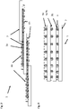
-
- (1)
- solar cell string
- (2)
- (2a, 2b, 2c) solar cells
- (3a, 3b)
- electrically conducting interconnect
- (4a, 4b)
- adhesives (optionally thermoadhesive foils)
- (5)
- vertical offset (gap) of neighboring solar cells in solar cell string
-
-
Fig. 1 schematically shows a shingledsolar cell string 1 with three consecutivesolar cells interconnects solar cell 2a (sun-directed) and continue asinterconnects 3b when located beneath solar cell (2b) (shaded).Adhesive foil 4a is transparent, whereasadhesive foil 4b may optionally not be transparent as it is shaded in operational use anyhow.Adhesive foil 4a attaches theinterconnects 3a to the top side ofsolar cell 2a and extends very little into thepartial overlap 5 ofsolar cells adhesive foil 4a contributes to the minimum vertical offset together with the height or diameter of theinterconnects 3a. In an alternative embodiment, the adhesive 4a does not extend into theoverlap 5 and the vertical offset is determined by the height or diameter of theinterconnects 3a only.Adhesive foil 4b attaches, i.e. fixates, theinterconnects 3b to the bottom side ofsolar cell 2b and may optionally extend into thepartial overlap 5 ofsolar cells interconnects solar cells overlap area 5 and may allow for limited mechanical flexibility, e.g. bending, depending on the shape, material properties and pliability of theinterconnects -
Fig. 2 is a side view of an embodiment of the solar cell string ofFig. 1 , wherein theadhesives interconnects solar cells 2 but do not extend into the overlap area, and wherein the vertical offset of the solar cells is essentially determined by the height or diameter of theinterconnects -
Fig. 3 is a side view of the solar cell string ofFig. 2 with the option of wire-shapedinterconnects solar cells 2 is determined essentially by the diameter of theinterconnects adhesive foils solar cells 2.
Claims (9)
- Solar cell string (1) for use in a photovoltaic module comprising(i) a string of at least two solar cells (2a, 2b, 2c) facing each other in opposite polarity, and shingled in string direction with or without partial overlap of solar cells (2a, 2b, 2c);(ii) at least one elongated electrically conducting interconnect (3a, 3b), optionally wire, ribbon or busbar, extending in string direction from one side of one solar cell to the opposite side of the next solar cell (2a, 2b, 2c) for mechanically and electrically connecting the positive and negative electrodes of the shingled solar cells (2a, 2b, 2c) in string direction on the alternating top and bottom sides of the solar cells; and(iii) at least two adhesives (4a, 4b), optionally thermoadhesive foils, covering the at least one elongated interconnect (3a, 3b) and at least part of the top or bottom side of each solar cell that comprises the elongated interconnect;with the proviso that (a) there is no horizontal gap between shingled solar cells, (b) the adhesives (4a, 4b) do not contact each other, do not extend beyond one solar cell, do not extend into the optional partial overlap of solar cells (2a, 2b, 2c), and at least partially cover and mechanically fixate the at least one interconnect (3a, 3b) to the solar cells (2a, 2b, 2c).
- The solar cell string (1) of claim 1, wherein the shingled solar cells overlap at least partially and the interconnect (3a, 3b) is not fixated to at least one or both of the solar cells in the overlap region.
- The solar cell string (1) of claim 1, wherein the shingled solar cells do not overlap.
- The solar cell string (1) of any of claims 1 to 3, wherein the at least one elongated interconnect (3a, 3b), optionally a wire, ribbon or bus bar, further connects all contact structures, optionally contact fingers on each solar cell.
- The solar cell string (1) of any of claims 1 to 4, wherein the height or diameter of the at least one elongated interconnect (3a, 3b) determines the minimum vertical offset, optionally gap (5) of neighboring solar cells in the solar cell string (1).
- The solar cell string (1) of any of claims 1 to 5, wherein the at least one interconnect (3a, 3b) is selected from the group consisting of bus bars, ribbons and metal wires, optionally metal wires coated with solderable material, optionally with Ag-, Cu-, Bi-, In-, Pb-, Sn- and combinations thereof- comprising solder, optionally SnBi- or In-comprising solder.
- The solar cell string (1) of any of claims 1 to 6, wherein the interconnect (3a, 3b) mechanically and electrically contacts a conductive layer on the solar cell
- The solar cell string (1) of any of claims 1 to 7, wherein the adhesive foils (4a, 4b) are or comprise a polymer foil, optionally selected from the group consisting of duroplasts, optionally EVAs (ethylene vinyl acetates), TPSEs (thermoplastic silicone elastomers), TPUs (thermoplastic polyurethanes), PETs (polyethylene terephthalates), TPOs (thermoplastic polyfin elastomers), ionomers, thermoplasts; optionally PVBs (polyvinylbutyrals), silicones, polyolefins (PO), PPs (polypropylenes); and combinations of thermoduroplasts, optionally a polymer foil thermoadhesive at temperatures in the range of 50 to 250 °C, optionally in the range of 60 to 200 °C, optionally in the range of 75 to 175 °C.
- A photovoltaic module comprising a solar cell string (1) according to any of claims 1 to 8.
Applications Claiming Priority (2)
| Application Number | Priority Date | Filing Date | Title |
|---|---|---|---|
| EP20172072.9A EP3905341A1 (en) | 2020-04-29 | 2020-04-29 | Improved solar cell string for use in a photovoltaic module |
| PCT/EP2021/060925 WO2021219599A1 (en) | 2020-04-29 | 2021-04-27 | Improved solar cell string for use in a photovoltaic module |
Publications (2)
| Publication Number | Publication Date |
|---|---|
| EP3970201A1 EP3970201A1 (en) | 2022-03-23 |
| EP3970201B1 true EP3970201B1 (en) | 2022-09-07 |
Family
ID=70480100
Family Applications (2)
| Application Number | Title | Priority Date | Filing Date |
|---|---|---|---|
| EP20172072.9A Withdrawn EP3905341A1 (en) | 2020-04-29 | 2020-04-29 | Improved solar cell string for use in a photovoltaic module |
| EP21720526.9A Active EP3970201B1 (en) | 2020-04-29 | 2021-04-27 | Improved solar cell string for use in a photovoltaic module |
Family Applications Before (1)
| Application Number | Title | Priority Date | Filing Date |
|---|---|---|---|
| EP20172072.9A Withdrawn EP3905341A1 (en) | 2020-04-29 | 2020-04-29 | Improved solar cell string for use in a photovoltaic module |
Country Status (10)
| Country | Link |
|---|---|
| US (1) | US12027637B2 (en) |
| EP (2) | EP3905341A1 (en) |
| JP (1) | JP7617944B2 (en) |
| CN (1) | CN115398651B (en) |
| AU (1) | AU2021262466B2 (en) |
| ES (1) | ES2927644T3 (en) |
| HU (1) | HUE060661T2 (en) |
| PL (1) | PL3970201T3 (en) |
| PT (1) | PT3970201T (en) |
| WO (1) | WO2021219599A1 (en) |
Families Citing this family (5)
| Publication number | Priority date | Publication date | Assignee | Title |
|---|---|---|---|---|
| KR20250052495A (en) * | 2019-05-23 | 2025-04-18 | 알파 어셈블리 솔루션스 인크. | Solder paste for module fabrication of solar cells |
| US20230352611A1 (en) * | 2022-04-28 | 2023-11-02 | Soraria Corporation | Shingled solar module including wire interconnect |
| WO2024080262A1 (en) * | 2022-10-11 | 2024-04-18 | 出光興産株式会社 | Interconnector, photoelectric conversion module, and paddle |
| JPWO2024080261A1 (en) * | 2022-10-11 | 2024-04-18 | ||
| CN120916495A (en) * | 2024-10-24 | 2025-11-07 | 隆基绿能科技股份有限公司 | Photovoltaic module and photovoltaic system |
Family Cites Families (18)
| Publication number | Priority date | Publication date | Assignee | Title |
|---|---|---|---|---|
| JP2567294Y2 (en) * | 1992-02-15 | 1998-04-02 | シャープ株式会社 | Solar cell module |
| AUPR174800A0 (en) * | 2000-11-29 | 2000-12-21 | Australian National University, The | Semiconductor processing |
| DE10239845C1 (en) | 2002-08-29 | 2003-12-24 | Day4 Energy Inc | Electrode for photovoltaic cells, photovoltaic cell and photovoltaic module |
| US20080223429A1 (en) * | 2004-08-09 | 2008-09-18 | The Australian National University | Solar Cell (Sliver) Sub-Module Formation |
| JP5025590B2 (en) * | 2008-08-05 | 2012-09-12 | 三洋電機株式会社 | Manufacturing method of solar cell module |
| DE102009051051A1 (en) * | 2009-10-28 | 2011-05-05 | Thermoplastik S.R.O. | Photovoltaic module, has solar cells electrically connected one below other, dilatation-receiving bearing provided in recess, and spraying poured or transformed molded article and plate connected with each other |
| US8951824B1 (en) * | 2011-04-08 | 2015-02-10 | Apollo Precision (Fujian) Limited | Adhesives for attaching wire network to photovoltaic cells |
| US20120325282A1 (en) * | 2011-06-24 | 2012-12-27 | Solopower, Inc. | Solar cells with grid wire interconnections |
| US20140345675A1 (en) * | 2011-09-29 | 2014-11-27 | Lindsey A. Clark | Photovoltaic cell interconnect |
| US20140124014A1 (en) * | 2012-11-08 | 2014-05-08 | Cogenra Solar, Inc. | High efficiency configuration for solar cell string |
| JP2016189444A (en) * | 2015-03-30 | 2016-11-04 | 日立化成株式会社 | Device and solar cell |
| WO2018003563A1 (en) * | 2016-06-28 | 2018-01-04 | 京セラ株式会社 | Solar cell module |
| EP3389099B1 (en) * | 2017-04-14 | 2020-04-01 | Meyer Burger (Switzerland) AG | Photovoltaic module, photovoltaic encapsulant and method of producing a photovoltaic module |
| CN107123696A (en) * | 2017-06-09 | 2017-09-01 | 崔鹏 | A kind of photovoltaic solar cell piece component |
| SG11202000352XA (en) | 2017-07-20 | 2020-02-27 | Meyer Burger Switzerland Ag | Stabilized shingled solar cell strings and methods for their production |
| US20190296166A1 (en) * | 2018-03-23 | 2019-09-26 | Miasolé Hi-Tech Corp. | Thin flexible modules |
| CN208271927U (en) * | 2018-06-06 | 2018-12-21 | 君泰创新(北京)科技有限公司 | Film with conductor wire, generating electricity on two sides solar battery string and battery component |
| CN108987509B (en) * | 2018-08-03 | 2024-11-01 | 浙江爱旭太阳能科技有限公司 | Double-sided shingled solar cell module and preparation method thereof |
-
2020
- 2020-04-29 EP EP20172072.9A patent/EP3905341A1/en not_active Withdrawn
-
2021
- 2021-04-27 ES ES21720526T patent/ES2927644T3/en active Active
- 2021-04-27 EP EP21720526.9A patent/EP3970201B1/en active Active
- 2021-04-27 PL PL21720526.9T patent/PL3970201T3/en unknown
- 2021-04-27 WO PCT/EP2021/060925 patent/WO2021219599A1/en not_active Ceased
- 2021-04-27 CN CN202180027775.6A patent/CN115398651B/en active Active
- 2021-04-27 JP JP2022566205A patent/JP7617944B2/en active Active
- 2021-04-27 AU AU2021262466A patent/AU2021262466B2/en active Active
- 2021-04-27 PT PT217205269T patent/PT3970201T/en unknown
- 2021-04-27 HU HUE21720526A patent/HUE060661T2/en unknown
- 2021-04-27 US US17/997,454 patent/US12027637B2/en active Active
Also Published As
| Publication number | Publication date |
|---|---|
| HUE060661T2 (en) | 2023-04-28 |
| EP3905341A1 (en) | 2021-11-03 |
| PL3970201T3 (en) | 2022-12-27 |
| CN115398651A (en) | 2022-11-25 |
| US12027637B2 (en) | 2024-07-02 |
| EP3970201A1 (en) | 2022-03-23 |
| AU2021262466B2 (en) | 2023-10-19 |
| JP7617944B2 (en) | 2025-01-20 |
| US20230223488A1 (en) | 2023-07-13 |
| AU2021262466A1 (en) | 2022-10-06 |
| WO2021219599A1 (en) | 2021-11-04 |
| ES2927644T3 (en) | 2022-11-08 |
| PT3970201T (en) | 2022-10-03 |
| JP2023527669A (en) | 2023-06-30 |
| CN115398651B (en) | 2025-06-06 |
Similar Documents
| Publication | Publication Date | Title |
|---|---|---|
| US12027637B2 (en) | Solar cell string for use in a photovoltaic module | |
| US20210036173A1 (en) | Stabilized shingled solar cell strings and methods for their production | |
| EP2220691B1 (en) | Busbar connection configuration to accommodate for cell misalignment | |
| JP3323573B2 (en) | Solar cell module and method of manufacturing the same | |
| US10734938B2 (en) | Packaging for solar roof tiles | |
| JP2009111034A (en) | Solar cell module and solar cell device using same | |
| CN112825337A (en) | Flexible solar cell array | |
| JP4776258B2 (en) | SOLAR CELL MODULE AND SOLAR CELL DEVICE HAVING THE SAME | |
| CN222721887U (en) | Photovoltaic module and photovoltaic system | |
| US10211356B2 (en) | Cell interconnects | |
| US11190128B2 (en) | Parallel-connected solar roof tile modules | |
| KR101542003B1 (en) | Solar cell module | |
| EP4156310A1 (en) | Solar cell module | |
| EP4102577A1 (en) | Improved parallel solar cell string assemblies for use in a photovoltaic module | |
| CA3212617A1 (en) | Solar cell string and method for producing a solar cell string | |
| CN120500156A (en) | Solar cell and photovoltaic module | |
| JPH0685304A (en) | Solar cell module integrated with roof material | |
| EP4372827A1 (en) | Solar cell module | |
| WO2023006640A1 (en) | Solar cell module | |
| CN119653876B (en) | Photovoltaic module and preparation method thereof | |
| CN222814780U (en) | Solar cells, solar strings, photovoltaic modules and photovoltaic power generation systems | |
| CN119653875A (en) | Solar cells, solar strings, photovoltaic modules and photovoltaic power generation systems | |
| CN121078821A (en) | Battery piece assembly, manufacturing method thereof, battery string and photovoltaic power generation system | |
| JP2012134247A (en) | Solar cell module and solar cell | |
| HK40028811A (en) | Packaging for solar roof tiles |
Legal Events
| Date | Code | Title | Description |
|---|---|---|---|
| STAA | Information on the status of an ep patent application or granted ep patent |
Free format text: STATUS: UNKNOWN |
|
| STAA | Information on the status of an ep patent application or granted ep patent |
Free format text: STATUS: THE INTERNATIONAL PUBLICATION HAS BEEN MADE |
|
| PUAI | Public reference made under article 153(3) epc to a published international application that has entered the european phase |
Free format text: ORIGINAL CODE: 0009012 |
|
| STAA | Information on the status of an ep patent application or granted ep patent |
Free format text: STATUS: REQUEST FOR EXAMINATION WAS MADE |
|
| 17P | Request for examination filed |
Effective date: 20211214 |
|
| AK | Designated contracting states |
Kind code of ref document: A1 Designated state(s): AL AT BE BG CH CY CZ DE DK EE ES FI FR GB GR HR HU IE IS IT LI LT LU LV MC MK MT NL NO PL PT RO RS SE SI SK SM TR |
|
| GRAP | Despatch of communication of intention to grant a patent |
Free format text: ORIGINAL CODE: EPIDOSNIGR1 |
|
| STAA | Information on the status of an ep patent application or granted ep patent |
Free format text: STATUS: GRANT OF PATENT IS INTENDED |
|
| INTG | Intention to grant announced |
Effective date: 20220630 |
|
| GRAS | Grant fee paid |
Free format text: ORIGINAL CODE: EPIDOSNIGR3 |
|
| GRAA | (expected) grant |
Free format text: ORIGINAL CODE: 0009210 |
|
| STAA | Information on the status of an ep patent application or granted ep patent |
Free format text: STATUS: THE PATENT HAS BEEN GRANTED |
|
| AK | Designated contracting states |
Kind code of ref document: B1 Designated state(s): AL AT BE BG CH CY CZ DE DK EE ES FI FR GB GR HR HU IE IS IT LI LT LU LV MC MK MT NL NO PL PT RO RS SE SI SK SM TR |
|
| DAV | Request for validation of the european patent (deleted) | ||
| DAX | Request for extension of the european patent (deleted) | ||
| REG | Reference to a national code |
Ref country code: GB Ref legal event code: FG4D |
|
| REG | Reference to a national code |
Ref country code: CH Ref legal event code: EP Ref country code: AT Ref legal event code: REF Ref document number: 1517783 Country of ref document: AT Kind code of ref document: T Effective date: 20220915 |
|
| REG | Reference to a national code |
Ref country code: DE Ref legal event code: R096 Ref document number: 602021000400 Country of ref document: DE |
|
| REG | Reference to a national code |
Ref country code: IE Ref legal event code: FG4D |
|
| REG | Reference to a national code |
Ref country code: PT Ref legal event code: SC4A Ref document number: 3970201 Country of ref document: PT Date of ref document: 20221003 Kind code of ref document: T Free format text: AVAILABILITY OF NATIONAL TRANSLATION Effective date: 20220926 |
|
| REG | Reference to a national code |
Ref country code: ES Ref legal event code: FG2A Ref document number: 2927644 Country of ref document: ES Kind code of ref document: T3 Effective date: 20221108 |
|
| REG | Reference to a national code |
Ref country code: LT Ref legal event code: MG9D |
|
| REG | Reference to a national code |
Ref country code: NL Ref legal event code: MP Effective date: 20220907 |
|
| PG25 | Lapsed in a contracting state [announced via postgrant information from national office to epo] |
Ref country code: SE Free format text: LAPSE BECAUSE OF FAILURE TO SUBMIT A TRANSLATION OF THE DESCRIPTION OR TO PAY THE FEE WITHIN THE PRESCRIBED TIME-LIMIT Effective date: 20220907 Ref country code: RS Free format text: LAPSE BECAUSE OF FAILURE TO SUBMIT A TRANSLATION OF THE DESCRIPTION OR TO PAY THE FEE WITHIN THE PRESCRIBED TIME-LIMIT Effective date: 20220907 Ref country code: NO Free format text: LAPSE BECAUSE OF FAILURE TO SUBMIT A TRANSLATION OF THE DESCRIPTION OR TO PAY THE FEE WITHIN THE PRESCRIBED TIME-LIMIT Effective date: 20221207 Ref country code: LV Free format text: LAPSE BECAUSE OF FAILURE TO SUBMIT A TRANSLATION OF THE DESCRIPTION OR TO PAY THE FEE WITHIN THE PRESCRIBED TIME-LIMIT Effective date: 20220907 Ref country code: LT Free format text: LAPSE BECAUSE OF FAILURE TO SUBMIT A TRANSLATION OF THE DESCRIPTION OR TO PAY THE FEE WITHIN THE PRESCRIBED TIME-LIMIT Effective date: 20220907 Ref country code: FI Free format text: LAPSE BECAUSE OF FAILURE TO SUBMIT A TRANSLATION OF THE DESCRIPTION OR TO PAY THE FEE WITHIN THE PRESCRIBED TIME-LIMIT Effective date: 20220907 |
|
| REG | Reference to a national code |
Ref country code: AT Ref legal event code: MK05 Ref document number: 1517783 Country of ref document: AT Kind code of ref document: T Effective date: 20220907 |
|
| PG25 | Lapsed in a contracting state [announced via postgrant information from national office to epo] |
Ref country code: HR Free format text: LAPSE BECAUSE OF FAILURE TO SUBMIT A TRANSLATION OF THE DESCRIPTION OR TO PAY THE FEE WITHIN THE PRESCRIBED TIME-LIMIT Effective date: 20220907 Ref country code: GR Free format text: LAPSE BECAUSE OF FAILURE TO SUBMIT A TRANSLATION OF THE DESCRIPTION OR TO PAY THE FEE WITHIN THE PRESCRIBED TIME-LIMIT Effective date: 20221208 |
|
| PG25 | Lapsed in a contracting state [announced via postgrant information from national office to epo] |
Ref country code: SM Free format text: LAPSE BECAUSE OF FAILURE TO SUBMIT A TRANSLATION OF THE DESCRIPTION OR TO PAY THE FEE WITHIN THE PRESCRIBED TIME-LIMIT Effective date: 20220907 Ref country code: RO Free format text: LAPSE BECAUSE OF FAILURE TO SUBMIT A TRANSLATION OF THE DESCRIPTION OR TO PAY THE FEE WITHIN THE PRESCRIBED TIME-LIMIT Effective date: 20220907 Ref country code: CZ Free format text: LAPSE BECAUSE OF FAILURE TO SUBMIT A TRANSLATION OF THE DESCRIPTION OR TO PAY THE FEE WITHIN THE PRESCRIBED TIME-LIMIT Effective date: 20220907 Ref country code: AT Free format text: LAPSE BECAUSE OF FAILURE TO SUBMIT A TRANSLATION OF THE DESCRIPTION OR TO PAY THE FEE WITHIN THE PRESCRIBED TIME-LIMIT Effective date: 20220907 |
|
| REG | Reference to a national code |
Ref country code: HU Ref legal event code: AG4A Ref document number: E060661 Country of ref document: HU |
|
| PG25 | Lapsed in a contracting state [announced via postgrant information from national office to epo] |
Ref country code: SK Free format text: LAPSE BECAUSE OF FAILURE TO SUBMIT A TRANSLATION OF THE DESCRIPTION OR TO PAY THE FEE WITHIN THE PRESCRIBED TIME-LIMIT Effective date: 20220907 Ref country code: IS Free format text: LAPSE BECAUSE OF FAILURE TO SUBMIT A TRANSLATION OF THE DESCRIPTION OR TO PAY THE FEE WITHIN THE PRESCRIBED TIME-LIMIT Effective date: 20230107 Ref country code: EE Free format text: LAPSE BECAUSE OF FAILURE TO SUBMIT A TRANSLATION OF THE DESCRIPTION OR TO PAY THE FEE WITHIN THE PRESCRIBED TIME-LIMIT Effective date: 20220907 |
|
| REG | Reference to a national code |
Ref country code: DE Ref legal event code: R097 Ref document number: 602021000400 Country of ref document: DE |
|
| PG25 | Lapsed in a contracting state [announced via postgrant information from national office to epo] |
Ref country code: NL Free format text: LAPSE BECAUSE OF FAILURE TO SUBMIT A TRANSLATION OF THE DESCRIPTION OR TO PAY THE FEE WITHIN THE PRESCRIBED TIME-LIMIT Effective date: 20220907 Ref country code: AL Free format text: LAPSE BECAUSE OF FAILURE TO SUBMIT A TRANSLATION OF THE DESCRIPTION OR TO PAY THE FEE WITHIN THE PRESCRIBED TIME-LIMIT Effective date: 20220907 |
|
| PLBE | No opposition filed within time limit |
Free format text: ORIGINAL CODE: 0009261 |
|
| STAA | Information on the status of an ep patent application or granted ep patent |
Free format text: STATUS: NO OPPOSITION FILED WITHIN TIME LIMIT |
|
| PG25 | Lapsed in a contracting state [announced via postgrant information from national office to epo] |
Ref country code: DK Free format text: LAPSE BECAUSE OF FAILURE TO SUBMIT A TRANSLATION OF THE DESCRIPTION OR TO PAY THE FEE WITHIN THE PRESCRIBED TIME-LIMIT Effective date: 20220907 |
|
| 26N | No opposition filed |
Effective date: 20230608 |
|
| PG25 | Lapsed in a contracting state [announced via postgrant information from national office to epo] |
Ref country code: LU Free format text: LAPSE BECAUSE OF NON-PAYMENT OF DUE FEES Effective date: 20230427 |
|
| REG | Reference to a national code |
Ref country code: BE Ref legal event code: MM Effective date: 20230430 |
|
| PG25 | Lapsed in a contracting state [announced via postgrant information from national office to epo] |
Ref country code: MC Free format text: LAPSE BECAUSE OF FAILURE TO SUBMIT A TRANSLATION OF THE DESCRIPTION OR TO PAY THE FEE WITHIN THE PRESCRIBED TIME-LIMIT Effective date: 20220907 |
|
| PG25 | Lapsed in a contracting state [announced via postgrant information from national office to epo] |
Ref country code: MC Free format text: LAPSE BECAUSE OF FAILURE TO SUBMIT A TRANSLATION OF THE DESCRIPTION OR TO PAY THE FEE WITHIN THE PRESCRIBED TIME-LIMIT Effective date: 20220907 |
|
| REG | Reference to a national code |
Ref country code: IE Ref legal event code: MM4A |
|
| PG25 | Lapsed in a contracting state [announced via postgrant information from national office to epo] |
Ref country code: BE Free format text: LAPSE BECAUSE OF NON-PAYMENT OF DUE FEES Effective date: 20230430 |
|
| PG25 | Lapsed in a contracting state [announced via postgrant information from national office to epo] |
Ref country code: IE Free format text: LAPSE BECAUSE OF NON-PAYMENT OF DUE FEES Effective date: 20230427 |
|
| PG25 | Lapsed in a contracting state [announced via postgrant information from national office to epo] |
Ref country code: IE Free format text: LAPSE BECAUSE OF NON-PAYMENT OF DUE FEES Effective date: 20230427 |
|
| PG25 | Lapsed in a contracting state [announced via postgrant information from national office to epo] |
Ref country code: BG Free format text: LAPSE BECAUSE OF FAILURE TO SUBMIT A TRANSLATION OF THE DESCRIPTION OR TO PAY THE FEE WITHIN THE PRESCRIBED TIME-LIMIT Effective date: 20220907 |
|
| REG | Reference to a national code |
Ref country code: DE Ref legal event code: R079 Ref document number: 602021000400 Country of ref document: DE Free format text: PREVIOUS MAIN CLASS: H01L0031050000 Ipc: H10F0019900000 |
|
| PG25 | Lapsed in a contracting state [announced via postgrant information from national office to epo] |
Ref country code: BG Free format text: LAPSE BECAUSE OF FAILURE TO SUBMIT A TRANSLATION OF THE DESCRIPTION OR TO PAY THE FEE WITHIN THE PRESCRIBED TIME-LIMIT Effective date: 20220907 |
|
| REG | Reference to a national code |
Ref country code: CH Ref legal event code: PL |
|
| PG25 | Lapsed in a contracting state [announced via postgrant information from national office to epo] |
Ref country code: CH Free format text: LAPSE BECAUSE OF NON-PAYMENT OF DUE FEES Effective date: 20240430 |
|
| PGFP | Annual fee paid to national office [announced via postgrant information from national office to epo] |
Ref country code: PL Payment date: 20250423 Year of fee payment: 5 Ref country code: DE Payment date: 20250428 Year of fee payment: 5 |
|
| PGFP | Annual fee paid to national office [announced via postgrant information from national office to epo] |
Ref country code: ES Payment date: 20250513 Year of fee payment: 5 |
|
| PGFP | Annual fee paid to national office [announced via postgrant information from national office to epo] |
Ref country code: HU Payment date: 20250429 Year of fee payment: 5 |
|
| PGFP | Annual fee paid to national office [announced via postgrant information from national office to epo] |
Ref country code: IT Payment date: 20250428 Year of fee payment: 5 |
|
| PGFP | Annual fee paid to national office [announced via postgrant information from national office to epo] |
Ref country code: PT Payment date: 20250417 Year of fee payment: 5 |
|
| PGFP | Annual fee paid to national office [announced via postgrant information from national office to epo] |
Ref country code: FR Payment date: 20250424 Year of fee payment: 5 |
|
| PG25 | Lapsed in a contracting state [announced via postgrant information from national office to epo] |
Ref country code: CY Free format text: LAPSE BECAUSE OF FAILURE TO SUBMIT A TRANSLATION OF THE DESCRIPTION OR TO PAY THE FEE WITHIN THE PRESCRIBED TIME-LIMIT; INVALID AB INITIO Effective date: 20210427 |
|
| PG25 | Lapsed in a contracting state [announced via postgrant information from national office to epo] |
Ref country code: TR Free format text: LAPSE BECAUSE OF FAILURE TO SUBMIT A TRANSLATION OF THE DESCRIPTION OR TO PAY THE FEE WITHIN THE PRESCRIBED TIME-LIMIT Effective date: 20220907 |
|
| GBPC | Gb: european patent ceased through non-payment of renewal fee |
Effective date: 20250427 |
|
| PG25 | Lapsed in a contracting state [announced via postgrant information from national office to epo] |
Ref country code: GB Free format text: LAPSE BECAUSE OF NON-PAYMENT OF DUE FEES Effective date: 20250427 |
|
| PG25 | Lapsed in a contracting state [announced via postgrant information from national office to epo] |
Ref country code: SI Free format text: LAPSE BECAUSE OF FAILURE TO SUBMIT A TRANSLATION OF THE DESCRIPTION OR TO PAY THE FEE WITHIN THE PRESCRIBED TIME-LIMIT Effective date: 20220907 |