EP3970176B1 - Electronic installation device - Google Patents
Electronic installation device Download PDFInfo
- Publication number
- EP3970176B1 EP3970176B1 EP20732882.4A EP20732882A EP3970176B1 EP 3970176 B1 EP3970176 B1 EP 3970176B1 EP 20732882 A EP20732882 A EP 20732882A EP 3970176 B1 EP3970176 B1 EP 3970176B1
- Authority
- EP
- European Patent Office
- Prior art keywords
- electronic installation
- circuit
- installation device
- accordance
- load
- Prior art date
- Legal status (The legal status is an assumption and is not a legal conclusion. Google has not performed a legal analysis and makes no representation as to the accuracy of the status listed.)
- Active
Links
- 238000009434 installation Methods 0.000 title claims description 67
- 239000004020 conductor Substances 0.000 claims description 81
- 239000010410 layer Substances 0.000 claims description 36
- 238000002844 melting Methods 0.000 claims description 23
- 230000008018 melting Effects 0.000 claims description 23
- 238000001514 detection method Methods 0.000 claims description 7
- 239000000463 material Substances 0.000 claims description 5
- 230000002441 reversible effect Effects 0.000 claims description 5
- 239000004065 semiconductor Substances 0.000 claims description 5
- 238000010438 heat treatment Methods 0.000 claims description 4
- 238000006243 chemical reaction Methods 0.000 claims 1
- 230000008878 coupling Effects 0.000 claims 1
- 238000010168 coupling process Methods 0.000 claims 1
- 238000005859 coupling reaction Methods 0.000 claims 1
- 230000002427 irreversible effect Effects 0.000 claims 1
- 239000002356 single layer Substances 0.000 claims 1
- 239000000758 substrate Substances 0.000 description 23
- 238000000034 method Methods 0.000 description 4
- 230000002829 reductive effect Effects 0.000 description 4
- 230000001960 triggered effect Effects 0.000 description 4
- 238000005516 engineering process Methods 0.000 description 3
- 230000001681 protective effect Effects 0.000 description 3
- 238000011144 upstream manufacturing Methods 0.000 description 3
- 239000011231 conductive filler Substances 0.000 description 2
- 229920001940 conductive polymer Polymers 0.000 description 2
- 230000003247 decreasing effect Effects 0.000 description 2
- 230000000694 effects Effects 0.000 description 2
- 239000011256 inorganic filler Substances 0.000 description 2
- 229910003475 inorganic filler Inorganic materials 0.000 description 2
- 239000000203 mixture Substances 0.000 description 2
- 229920000620 organic polymer Polymers 0.000 description 2
- RYGMFSIKBFXOCR-UHFFFAOYSA-N Copper Chemical compound [Cu] RYGMFSIKBFXOCR-UHFFFAOYSA-N 0.000 description 1
- 230000002159 abnormal effect Effects 0.000 description 1
- 238000000429 assembly Methods 0.000 description 1
- 230000000712 assembly Effects 0.000 description 1
- 238000003486 chemical etching Methods 0.000 description 1
- 229910052802 copper Inorganic materials 0.000 description 1
- 239000010949 copper Substances 0.000 description 1
- 239000012792 core layer Substances 0.000 description 1
- 230000001419 dependent effect Effects 0.000 description 1
- 239000003989 dielectric material Substances 0.000 description 1
- 238000010616 electrical installation Methods 0.000 description 1
- 239000003365 glass fiber Substances 0.000 description 1
- 230000017525 heat dissipation Effects 0.000 description 1
- 230000020169 heat generation Effects 0.000 description 1
- 238000009413 insulation Methods 0.000 description 1
- 239000000155 melt Substances 0.000 description 1
- 238000000059 patterning Methods 0.000 description 1
- 229920002120 photoresistant polymer Polymers 0.000 description 1
- 229920000728 polyester Polymers 0.000 description 1
- 229920000642 polymer Polymers 0.000 description 1
- 239000011347 resin Substances 0.000 description 1
- 229920005989 resin Polymers 0.000 description 1
- 230000000717 retained effect Effects 0.000 description 1
- 230000000630 rising effect Effects 0.000 description 1
Images


Classifications
-
- H—ELECTRICITY
- H02—GENERATION; CONVERSION OR DISTRIBUTION OF ELECTRIC POWER
- H02H—EMERGENCY PROTECTIVE CIRCUIT ARRANGEMENTS
- H02H3/00—Emergency protective circuit arrangements for automatic disconnection directly responsive to an undesired change from normal electric working condition with or without subsequent reconnection ; integrated protection
- H02H3/08—Emergency protective circuit arrangements for automatic disconnection directly responsive to an undesired change from normal electric working condition with or without subsequent reconnection ; integrated protection responsive to excess current
- H02H3/10—Emergency protective circuit arrangements for automatic disconnection directly responsive to an undesired change from normal electric working condition with or without subsequent reconnection ; integrated protection responsive to excess current additionally responsive to some other abnormal electrical conditions
-
- H—ELECTRICITY
- H01—ELECTRIC ELEMENTS
- H01H—ELECTRIC SWITCHES; RELAYS; SELECTORS; EMERGENCY PROTECTIVE DEVICES
- H01H71/00—Details of the protective switches or relays covered by groups H01H73/00 - H01H83/00
- H01H71/10—Operating or release mechanisms
- H01H71/12—Automatic release mechanisms with or without manual release
- H01H71/40—Combined electrothermal and electromagnetic mechanisms
-
- H—ELECTRICITY
- H02—GENERATION; CONVERSION OR DISTRIBUTION OF ELECTRIC POWER
- H02H—EMERGENCY PROTECTIVE CIRCUIT ARRANGEMENTS
- H02H3/00—Emergency protective circuit arrangements for automatic disconnection directly responsive to an undesired change from normal electric working condition with or without subsequent reconnection ; integrated protection
- H02H3/08—Emergency protective circuit arrangements for automatic disconnection directly responsive to an undesired change from normal electric working condition with or without subsequent reconnection ; integrated protection responsive to excess current
- H02H3/085—Emergency protective circuit arrangements for automatic disconnection directly responsive to an undesired change from normal electric working condition with or without subsequent reconnection ; integrated protection responsive to excess current making use of a thermal sensor, e.g. thermistor, heated by the excess current
-
- H—ELECTRICITY
- H01—ELECTRIC ELEMENTS
- H01H—ELECTRIC SWITCHES; RELAYS; SELECTORS; EMERGENCY PROTECTIVE DEVICES
- H01H85/00—Protective devices in which the current flows through a part of fusible material and this current is interrupted by displacement of the fusible material when this current becomes excessive
- H01H85/02—Details
- H01H85/0241—Structural association of a fuse and another component or apparatus
- H01H2085/0283—Structural association with a semiconductor device
-
- H—ELECTRICITY
- H01—ELECTRIC ELEMENTS
- H01H—ELECTRIC SWITCHES; RELAYS; SELECTORS; EMERGENCY PROTECTIVE DEVICES
- H01H47/00—Circuit arrangements not adapted to a particular application of the relay and designed to obtain desired operating characteristics or to provide energising current
- H01H47/22—Circuit arrangements not adapted to a particular application of the relay and designed to obtain desired operating characteristics or to provide energising current for supplying energising current for relay coil
-
- H—ELECTRICITY
- H01—ELECTRIC ELEMENTS
- H01H—ELECTRIC SWITCHES; RELAYS; SELECTORS; EMERGENCY PROTECTIVE DEVICES
- H01H85/00—Protective devices in which the current flows through a part of fusible material and this current is interrupted by displacement of the fusible material when this current becomes excessive
- H01H85/02—Details
- H01H85/04—Fuses, i.e. expendable parts of the protective device, e.g. cartridges
- H01H85/041—Fuses, i.e. expendable parts of the protective device, e.g. cartridges characterised by the type
- H01H85/046—Fuses formed as printed circuits
-
- H—ELECTRICITY
- H01—ELECTRIC ELEMENTS
- H01H—ELECTRIC SWITCHES; RELAYS; SELECTORS; EMERGENCY PROTECTIVE DEVICES
- H01H89/00—Combinations of two or more different basic types of electric switches, relays, selectors and emergency protective devices, not covered by any single one of the other main groups of this subclass
-
- H—ELECTRICITY
- H05—ELECTRIC TECHNIQUES NOT OTHERWISE PROVIDED FOR
- H05K—PRINTED CIRCUITS; CASINGS OR CONSTRUCTIONAL DETAILS OF ELECTRIC APPARATUS; MANUFACTURE OF ASSEMBLAGES OF ELECTRICAL COMPONENTS
- H05K1/00—Printed circuits
- H05K1/02—Details
- H05K1/0296—Conductive pattern lay-out details not covered by sub groups H05K1/02 - H05K1/0295
- H05K1/0298—Multilayer circuits
Definitions
- the invention relates to an electronic installation device according to the preamble of claim 1.
- An installation device according to the preamble of claim 1 is from DE 10 2017 110897 A1 known.
- Electronic installation devices of this type can contain switch contacts, e.g. of a relay, or power semiconductor components for carrying current under load and electronic control devices for driving a relay coil or for driving power semiconductor components.
- Such electronic installation devices are often used in electrical installation systems for building technology and are designed for a load current that is well below the nominal current, e.g. 16 amperes, of the circuits that are usual in building installation.
- a load current that is well below the nominal current, e.g. 16 amperes, of the circuits that are usual in building installation.
- blind switches, timers, etc. are designed for a load current in the range between 3 amperes and 8 amperes.
- the electronic installation devices must be tested with the tripping current of an upstream fuse element, preferably a miniature circuit breaker, of the building installation when tested in accordance with the standards. Due to the difference between the load current of an electronic installation device and the tripping current of the upstream building-side safety element, the electronic installation device would be protected insufficiently, namely too high. In the event of an overcurrent in the range between the device's rated current and the tripping current of the upstream fuse element of the building installation, the electronic installation device would be unprotected and could be destroyed.
- an upstream fuse element preferably a miniature circuit breaker
- overload is defined as exceeding the permissible current in the electrically undamaged circuit.
- the current-related heat development destroys electrical conductors and components by exceeding permissible limit temperatures.
- An overload protection device detects the heating of conductors and/or components and switches off the circuit at least temporarily.
- Short-circuit currents and overload currents result in different technical requirements for protective devices. Both in the event of a short circuit and an overload, current-carrying lines heat up to impermissibly high temperatures. The main difference is that in the event of a short-circuit with high short-circuit currents, the inadmissibly high amount of heat can be reached in fractions of an electrical half-wave. Even with high short-circuit currents, fuses melt within a sufficiently short time. In the event of an overload, currents occur that are only slightly above the maximum permissible load capacity of a cable and only heat up the cable to impermissibly high temperatures after a long period of time. In such a loaded circuit, a preferably reversible fuse can ensure that the impermissible high temperature cannot be reached on the conductors and components and there is protection against overload.
- self-resetting fuses for example electrical components with PTC characteristics (positive temperature coefficient)
- PTC characteristics positive temperature coefficient
- PTC thermistor has low resistance at normal temperature. If the PTC thermistor heats up, for example due to an external heat supply, it becomes highly resistive, which severely restricts the current flow. If the heat supply is reduced, the PTC thermistor cools down and becomes low-resistance again.
- Electronic installation devices are mainly implemented in small parts on conductor track packages.
- An implementation of a complete overcurrent protection based on printed conductor structures is not yet known, since In particular, the usual conductor path geometry with low layer thicknesses and large surfaces is not suitable for loading with different current limit values.
- Short-circuit protection with a fuse requires a higher melting integral at all other points of the conductor track structure and consequently large conductor track surfaces.
- the heat generation and dissipation of a conductor required for overload protection by means of PTC elements cannot be realized with the usual width of the conductor track. However, a required tapered conductor track would be destroyed in the event of a short circuit.
- a realization of an overload protection based on PTC means that no separate short-circuit protection would be possible on the printed conductor package.
- the corresponding fuse in the house installation usually a reversible automatic device, would have to be replaced according to the lower nominal current of the installation device.
- the object of the present invention is therefore to eliminate the disadvantages mentioned above and to implement an electronic installation device with device-specific protection devices against short circuits and against overload.
- the invention according to claim 1 has the advantage that the electronic installation device according to the invention by a combination of two specific coordinated protective devices is protected against overcurrent.
- a first overcurrent protection device protects against a short circuit, while a second overcurrent protection device protects against overload.
- the electronic installation device can be connected in series with a load.
- the electronic installation device includes a load circuit and a control circuit, which are thermally and physically/electrically coupled.
- the load circuit includes a first overcurrent protection device, a resistive element, and a circuit breaking element, which are positionable in series between a power source and an electrical load.
- An overcurrent detection device interacts with a control device as a second overcurrent protection device.
- the control device is arranged in the control circuit and is operatively connected to the circuit-breaking element in the load circuit.
- the overcurrent detection device can comprise a sensor element in the control circuit, preferably a reversible electrical component, for example in the form of a positive temperature coefficient (PTC) thermistor, and a resistance element in the load circuit which is thermally coupled to the PTC element.
- the resistance element runs as a galvanically isolated conductor below the PTC element.
- the electronic installation device can be implemented at least partially on a printed circuit board arrangement and can have the first overcurrent protection device in the form of a fuse in the load circuit, which protects the device's own electrical components and conductors in the event of a short circuit. This means that the melting integral of the protected components and conductors is higher than the melting integral of the fuse.
- the fuse is only designed for short-circuits and not for overloads.
- the resistive element in the form of a conductor track of the load circuit is specifically designed not to be destroyed in the event of a short circuit on the one hand and to enable the thermal energy to be detected in the event of an overload on the other.
- the conductor track can consist of two parallel conductor tracks of different widths. The width ratio is preferably 5 to 1.
- the wide strip conductor absorbs the short-circuit current, while the narrow strip conductor is used to detect an overload situation.
- the common melting integral of both conductor tracks is higher than the melting integral of the safety fuse.
- the electronic installation device Under normal operating conditions, the electronic installation device is in a low-temperature, low-resistance state. In the event of a short circuit, the current increases very quickly and melts the fusible conductor in the first overcurrent protection device, which permanently interrupts the flow of current through the fuse. Since the common melting integral of the two conductor tracks of the resistance element is higher, there is no damage at this point. The narrow conductor track is not destroyed in the process, since when there is a high current flow in the event of a short circuit, the current uses the path of least resistance via the sufficiently dimensioned wide conductor track. The safety fuse does not trigger in the event of an overload in the area between the short-circuit current (fuse tripping current) and the nominal current of the installation device.
- the current through the resistive element increases comparatively slowly, with the ambient temperature of the narrow conductor track in particular increasing excessively and being maintained for longer than the normal operating time.
- the sensing element is "triggered” by the ambient temperature of the trace, that is, transformed into a high-temperature, high-resistance state, so the current is significantly reduced.
- the change in resistance and current values is "communicated” to the controller and causes therein the circuit breaking element, e.g. B. a relay or power semiconductor component, changes in the load circuit from a normal operating state to a tripping state and thus also the load is switched off.
- the circuit breaking element e.g. B. a relay or power semiconductor component
- the sensor element can form a voltage divider with a resistor, the changing voltage of which is read into a microcontroller and processed. If an overload is detected, the relay or power semiconductor component connected to the microcontroller and thus also the load in the load circuit are switched off. Alternatively, it is also possible to switch off in the event of an overload without a microcontroller. If the overload current in the load circuit continues to rise, the narrow strip conductor of the resistance element continues to heat up until the decreasing control current of the sensor element falls below the holding current of the relay. The relay drops out and opens the load circuit. The sensor element remains in the triggered state until the temperature returns to normal and has been allowed to cool. This is followed by a return to the normal state, i.e. the load is switched on again. The sensing element is not placed in series with the load and can therefore operate at current levels much lower than the normal circuit flowing through the load.
- the width of the two conductor tracks of the resistance element is determined according to the following rules.
- the energy that is absorbed in the form of the melting integral is relevant for short-circuit considerations.
- the melting integral of the conductor tracks of the installation device must be higher than the melting integral of the fuse.
- the common melting integral of the two conductor tracks of the resistance element must also be designed according to this specification.
- the ratio of Melting integrals of the conductor tracks to each other is preferably in a ratio greater than 25.
- the diameter of the round conductor can be determined by converting the melting integral of the fuse related to a round conductor.
- the resulting cross section can be converted to the minimum width of the two conductor tracks. Assuming a 25 to 1 ratio for the melting integrals of the two traces, the ratio of the width of the traces is 5 to 1. This assumes that the two traces are made of the same material and have the same thickness.
- the electronic installation device can at least partially have a layered or packaged arrangement of printed circuit boards, which consists of one or more substrate layers on which electrical components and/or conductor tracks can be arranged on one or both sides.
- the two overcurrent protection devices are advantageously formed on the two outer main surfaces of the printed circuit board arrangement.
- the first overcurrent protection device in the form of a safety fuse, can be arranged on a lower substrate layer, and at least the sensor element of the second overcurrent protection device, in the form of a PTC element, can be arranged on an upper substrate layer.
- the parallel-connected conductor tracks of the resistance element are arranged below the sensor element.
- the correspondingly structured resistance element can advantageously consist of a wide conductor track and a tapered conductor track and can be arranged in different substrate layers of the printed circuit board structure.
- the narrow strip conductor can be arranged near the surface or on the surface of the outer layer in order to enable the use of a sensor element on the surface (SMD technology) of the printed circuit board arrangement.
- the tapered trace can be a have a reduced width or a thinned height dimension.
- the various layers of the circuit board structure serve to maximize the area of the conductor tracks in order to be able to withstand a short-circuit current.
- Common height FR4 is used as the standard dielectric.
- Suitable sensor elements consist of a PTC conductive polymer, ie a composition comprising an organic polymer and a particulate conductive filler and/or a conductive inorganic filler.
- Electronic installation devices are often used to protect circuit arrangements with device-specific relatively high current and relatively low voltage loads, such as blind switches, time switches or fans. Circuits of this type typically contain electrical loads which cause overcurrents when the load, for example a motor, is started or under difficult operating conditions.
- An advantage of the electronic installation switch with the integrated overcurrent protection devices is that it can be used safely in existing circuits that are intrinsically over-protected.
- a specific (higher) device-internal short-circuit protection can be used, which neither replaces the usual circuit breakers of the house installation nor has a (lower) value (e.g. 10 amperes instead of 8 amperes) based on the overload current to minimize the effect of temperature.
- circuit board assembly remain unchanged.
- the material and material thickness of substrates, insulating layers and conductor tracks remain the same.
- the conductor track cross-section can also be realized with an optimized width-to-thickness ratio, so that small product dimensions can be produced compactly and cost-effectively in a small space.
- the use of and assembly with electronic components can also be retained.
- the principles of the present invention may be employed in larger circuit board assemblies and subassemblies that include printed circuit traces and components.
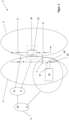
- the electronic installation device 1 shows a basic circuit arrangement for an electronic installation device 1.
- the electronic installation device 1 can preferably be connected in series with a load (not shown).
- the electronic installation device 1 comprises a load circuit 2 and a control circuit 3, which are thermally, physically and/or electrically coupled.
- the electronic installation device 1 is protected against overcurrent by a combination of two specific, coordinated protective devices.
- a first overcurrent protection device 4 protects against a short circuit, while a second overcurrent protection device 5 protects against overload.
- the electronic installation device 1 contains a circuit-breaking element 6 in the form of a switching contact of a relay 7 with which the electrical connection of the load to a voltage supply can be switched on and off.
- the relay 7 is controlled by a control device 8 in the control circuit 3, which supplies switching commands to a coil of the relay 7.
- the load circuit 2 comprises a first overcurrent protection device 4, a resistance element 9 and the circuit breaking element 6, which are arranged in series between a power source (not shown) and an electric load.
- An overcurrent detection device 10 acts together with the control device 8 as a second overcurrent protection device 5.
- the control device 8 is arranged in the control circuit 3 and functionally connected to the circuit-breaking element 6 in the load circuit 2.
- the overcurrent detection device 10 includes a sensor element 11 in the control circuit 3, preferably a reversible electrical component in the form of a positive PTC thermistor Temperature coefficient (PTC), and the resistance element 9 in the load circuit 2, which is thermally coupled to the PTC element 11.
- PTC PTC thermistor Temperature coefficient
- the resistance element 9 runs as a galvanically isolated conductor below the PTC element 11.
- the electronic installation device 1 is at least partially implemented on a printed circuit board structure 12 and has the first overcurrent protection device 4 in the form of a fuse in the load circuit 2, which protects the device's own electrical components and conductors in the event of a short circuit.
- the melting integral of the protected components and conductor tracks is higher than the melting integral of fuse 4.
- Fuse 4 is only designed for short circuits and not for overload.
- the certified fuse 4 used is designed to minimize temperature influences and to process a tripping current. In the event of a short circuit, the load circuit 2 is permanently interrupted by the fuse 4.
- the resistance element 9 in the form of a conductor track of the load circuit is designed specifically so that it is not destroyed in the event of a short circuit and also allows the thermal energy to be detected in the event of an overload.
- the conductor track consists of two parallel conductor tracks 13 and 14 of different widths.
- the width ratio is preferably 5 to 1.
- the wide strip conductor 14 absorbs the short-circuit current, while the narrow strip conductor 13 serves to detect the overload current.
- the common melting integral of both conductor tracks 13 and 14 is higher than the melting integral of fuse 4.
- the electrical network of a house installation can supply the operating current for the electronic installation device 1 .
- the load control circuit 2 that Circuit breaking element 6 of relay 7 is closed
- the operating current flows to the load, e.g. a brushed motor with relatively high current for a blind control.
- a control power source separate from the primary power source, provides control power for the control circuit 3.
- the control current flows to a coil of the relay 7 and normally causes the circuit breaker element 6 to close, thereby closing the load circuit 2.
- the electronic installation device 1 is in a low-temperature, low-resistance state.
- a fault current is a level of current that damages one of the components of an electrical circuit.
- the current rises very quickly and causes the fusible conductor in the first overcurrent protection device 4 to melt, as a result of which the flow of current is permanently interrupted. Since the common melting integral of the two conductor tracks 13 and 14 of the resistance element 9 is higher, there is no damage at this point.
- the narrow strip conductor 13 is not destroyed in the process, since when there is a high current flow in the event of a short circuit, the current uses the path of least resistance via the sufficiently dimensioned wide strip conductor 14 .
- the safety fuse 4 does not trigger in the event of an overload in the range between the short-circuit current (fuse tripping current) and the rated current of the electronic installation device 1 .
- the current through the resistance element 9 rises quickly but comparatively little, with the ambient temperature of the narrow conductor track 13 in particular rising excessively and being maintained for longer than the normal operating time.
- the PTC element 11 is "triggered” by the ambient temperature of the narrow conductor line 13, ie into a high temperature and high resistance state converted so that the current is significantly reduced.
- the change in the resistance and current values is "communicated” to the control device 8 .
- the PTC element 11 forms a voltage divider with a resistor 15, the changing voltage of which is read into a microcontroller 16 and processed.
- the relay 7 connected to an output 17 of the microcontroller 16 via a transistor 18 is switched off and the corresponding functionally coupled circuit breaker element 6 opens and the load is thus also switched off.
- Different operating modes can be set on the microcontroller 16 . For example, it can be specified whether the load should be switched on again automatically after a while, or only after a new switch-on command or after the interruption of load circuit 2 has been reset. The tripping characteristic can also be selected.
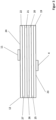
- a possible printed circuit board structure 12 of the electronic installation device 1 which consists of one or more substrate layers 19 to 22, a dielectric core layer with electrical components arranged on one or both sides and/or have conductor tracks.
- the two overcurrent protection devices 4 and 5 are formed at least partially on the two outer main surfaces 23 and 24 of the circuit board structure 12 .
- On the lower substrate layer 19 is the first overcurrent protection device, in the form of a safety fuse 4, and on the upper substrate layer 22 is at least the sensor element 11 of the second overcurrent protection device 5, in the form of a PTC element.
- Conductor tracks 13 and 14 of resistance element 9, which are electrically connected in parallel, are arranged below the PTC element.
- the correspondingly structured conductor track is arranged in different substrate layers of the circuit board structure 12 .
- the tapered conductive line 13 is arranged in the substrate layer 20 while the wide conductive line 14 is arranged in the substrate layer 21 .
- the two conductor tracks 13 and 14 are directly connected by conductive vias.
- the narrow strip conductor 13 is arranged close to the surface in the layer 20 in order to enable the use of a PTC element 11 on the surface (SMD technology).
- the PTC element 11 on the substrate layer 19 is in thermal contact with the substrate layer 20 just above the surface of the tapered conductor track 13 so that heat is generated there due to an overcurrent condition and is effectively transferred to the PTC element 11, so that as before explains a control signal is generated.
- the layers of circuit board assembly 12 are as thin as is structurally practical.
- the dielectric material forming the substrate can be a thin polyester material or other suitable thin flexible substrate.
- a thin but relatively rigid glass fiber reinforced resin substrate may also be used.
- the patterning of the copper layers can be accomplished by conventional photoresist and chemical etching techniques known to those skilled in the art.
- the various layers of the circuit board assembly are used to maximize the area of the Conductor tracks to withstand a short-circuit current.
- layers 25 to 27 of FR4 of a common height are used as the standard dielectric.
- Suitable PTC elements 11 consist of a PTC conductive polymer, ie a composition comprising an organic polymer and a particulate conductive filler and/or a conductive inorganic filler.
Description
Die Erfindung betrifft ein elektronisches Installationsgerät nach dem Oberbegriff des Patentanspruches 1. Ein Installationsgerät gemäß dem Oberbegriff des Anspruchs 1 ist aus der
Derartige elektronische Installationsgeräte können Schaltkontakte, z.B. eines Relais, oder Leistungshalbleiterbauelemente zur Laststromführung und elektronische Steuereinrichtungen zur Ansteuerung einer Relaisspule oder zur Ansteuerung von Leistungshalbleiterbauelementen enthalten.Electronic installation devices of this type can contain switch contacts, e.g. of a relay, or power semiconductor components for carrying current under load and electronic control devices for driving a relay coil or for driving power semiconductor components.
Häufig werden solche elektronischen Installationsgeräte in elektrischen Installationssystemen der Gebäudetechnik eingesetzt und sind für einen Laststrom ausgelegt, der deutlich unter dem Nennstrom, z.B. 16 Ampere, der in der Gebäudeinstallation üblichen Stromkreise liegt. Beispielsweise sind Jalousieschalter, Zeitschaltuhren etc. für einen Laststrom in Bereichen zwischen 3 Ampere und 8 Ampere ausgelegt.Such electronic installation devices are often used in electrical installation systems for building technology and are designed for a load current that is well below the nominal current, e.g. 16 amperes, of the circuits that are usual in building installation. For example, blind switches, timers, etc. are designed for a load current in the range between 3 amperes and 8 amperes.
Die elektronischen Installationsgeräte müssen bei normgerechter Prüfung mit dem Auslösestrom eines vorgeschalteten Sicherungselementes, vorzugsweise einem Leitungsschutzschalter, der Gebäudeinstallation geprüft werden. Aufgrund der Differenz zwischen dem Laststrom eines elektronischen Installationsgerätes und dem Auslösestrom des vorgeschalteten gebäudeseitigen Sicherungselementes wäre das elektronische Installationsgerät unzureichend, nämlich zu hoch, abgesichert. Bei einem Überstrom im Bereich zwischen dem Geräte-Nennstrom und dem Auslösestrom des vorgeschalteten Sicherungselementes der Gebäudeinstallation wäre das elektronische Installationsgerät ungeschützt und könnte zerstört werden.The electronic installation devices must be tested with the tripping current of an upstream fuse element, preferably a miniature circuit breaker, of the building installation when tested in accordance with the standards. Due to the difference between the load current of an electronic installation device and the tripping current of the upstream building-side safety element, the electronic installation device would be protected insufficiently, namely too high. In the event of an overcurrent in the range between the device's rated current and the tripping current of the upstream fuse element of the building installation, the electronic installation device would be unprotected and could be destroyed.
Unter sicherheitstechnischen Aspekten ist in solchen Fällen die Anordnung einer geräteeigenen Sicherung erforderlich, um vor Überstrom zu schützen. Es ist bekannt, in elektronischen Systemen mit einem Lastkreis und mit einem Steuerstromkreis schnell ansprechende Schmelzsicherungen, die vorzugsweise im Lastkreis angeordnet, als geräteeigene Sicherungen einzusetzen. Elektronische Systeme werden durch eine derartige Überstromschutzeinrichtung zuverlässig gegen einen Kurzschlussstrom im Lastkreis geschützt.From a safety point of view, it is necessary in such cases to install a device-specific fuse to protect against overcurrent. In electronic systems with a load circuit and a control circuit, it is known to use quick-acting fuses, which are preferably arranged in the load circuit, as device-specific fuses. Such an overcurrent protection device reliably protects electronic systems against a short-circuit current in the load circuit.
Wenn im Lastkreis ein Strom fließt, der kleiner als der Kurzschlussstrom, aber größer als der Geräte-Nennstrom ist, können elektrische Bauelemente weiterhin geschädigt werden. Allgemein ist diese sogenannte Überlast als ein Überschreiten des zulässigen Stromes im elektrisch unbeschädigten Stromkreis definiert. Dabei zerstört die strombedingte Wärmeentwicklung elektrische Leiter und Bauelemente durch Überschreiten zulässiger Grenztemperaturen. Eine Überlastschutzeinrichtung detektiert die Erwärmung von Leitern und/oder Bauelementen und schaltet den Stromkreis zumindest temporär ab.If a current flows in the load circuit that is less than the short-circuit current but greater than the device's nominal current, electrical components can continue to be damaged. In general, this so-called overload is defined as exceeding the permissible current in the electrically undamaged circuit. The current-related heat development destroys electrical conductors and components by exceeding permissible limit temperatures. An overload protection device detects the heating of conductors and/or components and switches off the circuit at least temporarily.
Kurzschlussströme und Überlastströme bedingen unterschiedliche technische Anforderungen an Schutzeinrichtungen. Sowohl bei Kurzschluss als auch bei Überlast erwärmen sich stromführende Leitungen auf unzulässig hohe Temperaturen. Wesentlicher Unterschied ist, dass im Kurzschlussfall bei hohen Kurzschlussströmen die unzulässig hohe Wärmemenge schon in Bruchteilen einer elektrischen Halbschwingung erreicht werden kann. Schmelzsicherungen schmelzen auch bei hohen Kurzschlussströmen innerhalb einer ausreichend kurzen Zeit ab. Im Überlastfall treten Ströme auf, die nur wenig oberhalb der max. dauernd zulässigen Belastbarkeit einer Leitung liegen, und erwärmen die Leitung erst nach längerer Zeit auf unzulässig hohe Temperaturen. In einem so belasteten Stromkreis kann eine, vorzugsweise reversible, Sicherung gewährleisten, dass die unzulässig hohe Temperatur an den Leitern und Bauelementen nicht erreicht werden kann und ein Schutz bei Überlast existiert.Short-circuit currents and overload currents result in different technical requirements for protective devices. Both in the event of a short circuit and an overload, current-carrying lines heat up to impermissibly high temperatures. The main difference is that in the event of a short-circuit with high short-circuit currents, the inadmissibly high amount of heat can be reached in fractions of an electrical half-wave. Even with high short-circuit currents, fuses melt within a sufficiently short time. In the event of an overload, currents occur that are only slightly above the maximum permissible load capacity of a cable and only heat up the cable to impermissibly high temperatures after a long period of time. In such a loaded circuit, a preferably reversible fuse can ensure that the impermissible high temperature cannot be reached on the conductors and components and there is protection against overload.
Mit einer einzigen geräteinternen Vorsicherung kann sowohl der Kurzschlussfall als auch der Überlastfall abgesichert werden. Dabei orientiert sich die Bemessung der Schmelzsicherung allerdings an dem niedrigeren Wert für den Überlastfall. Dies hat zur Folge, dass die Sicherung öfter als notwendig auslöst. Nachteilig ist, dass solche Schmelzsicherungen nach Auslösen zerstört sind und damit ausgetauscht werden müssen, um die Funktionsfähigkeit des Geräts nach Beseitigung der Überlastsituation wieder her zu stellen.With a single device-internal back-up fuse, both short-circuit and overload can be protected. However, the dimensioning of the safety fuse is based on the lower value for an overload situation. As a result, the fuse trips more often than necessary. The disadvantage is that such safety fuses are destroyed after they have been triggered and therefore have to be replaced in order to restore the functionality of the device after the overload situation has been eliminated.
Bekannte Geräteschutzschalter oder Leitungsschutzschalter, die beide Überstromfälle spezifisch absichern, lassen sich bei elektronischen Geräten, die kleinteilig und hauptsächlich auf Leiterbahnen realisiert werden, aufgrund ihrer Größe und Struktur nicht einsetzen. Thermische Schutzeinrichtungen mit mechanischen Komponenten lassen sich als Überlastschutz aufgrund ihrer Größe ebenfalls nicht verwenden.Known device circuit breakers or miniature circuit breakers, which specifically protect both cases of overcurrent, cannot be used in electronic devices that are implemented in small parts and mainly on conductor tracks because of their size and structure. Thermal protection devices with mechanical components cannot be used as overload protection either because of their size.
Des Weiteren sind selbstrückstellende Sicherungen, beispielsweise elektrische Bauelemente mit PTC-Charakteristik (positive temperature coefficient), bekannt, die aus einem Kaltleiter auf Polymerbasis mit nichtlinearem Widerstandsverlauf bestehen. Dieser Kaltleiter ist bei Normaltemperatur niederohmig. Erwärmt sich der Kaltleiter beispielsweise durch externe Wärmezufuhr, wird er hochohmig, wodurch der Stromfluss stark beschränkt wird. Wird die Wärmezufuhr reduziert, kühlt der Kaltleiter ab und wird wieder niederohmig.Furthermore, self-resetting fuses, for example electrical components with PTC characteristics (positive temperature coefficient), are known, which consist of a polymer-based PTC thermistor with a non-linear resistance profile. This PTC thermistor has low resistance at normal temperature. If the PTC thermistor heats up, for example due to an external heat supply, it becomes highly resistive, which severely restricts the current flow. If the heat supply is reduced, the PTC thermistor cools down and becomes low-resistance again.
Elektronische Installationsgeräte sind überwiegend kleinteilig auf Leiterbahnpaketen realisiert. Eine Umsetzung eines vollständigen Überstromschutzes auf Basis von Leiterbahnstrukturen ist bisher nicht bekannt, da insbesondere die übliche Leiterbahngeometrie mit geringen Schichtdicken und großen Oberflächen für die Belastung mit unterschiedlichen Stromgrenzwerten nicht geeignet ist. Die Kurzschluss-Absicherung mit einer Schmelzsicherung erfordert an allen übrigen Stellen der Leiterbahnstruktur ein höheres Schmelzintegral und folglich große Leiterbahnoberflächen. Die für eine Überlastabsicherung mittels PTC-Elemente notwendige Wärmeerzeugung und -abgabe eines Leiters lässt sich dagegen mit der üblichen Leiterbahnbreite nicht realisieren. Eine erforderliche verjüngte Leiterbahn würde aber im Kurzschlussfall zerstört werden.Electronic installation devices are mainly implemented in small parts on conductor track packages. An implementation of a complete overcurrent protection based on printed conductor structures is not yet known, since In particular, the usual conductor path geometry with low layer thicknesses and large surfaces is not suitable for loading with different current limit values. Short-circuit protection with a fuse requires a higher melting integral at all other points of the conductor track structure and consequently large conductor track surfaces. On the other hand, the heat generation and dissipation of a conductor required for overload protection by means of PTC elements cannot be realized with the usual width of the conductor track. However, a required tapered conductor track would be destroyed in the event of a short circuit.
Eine Realisierung einer Überlastsicherung auf PTC-Basis zur Folge, dass auf dem Leiterbahnpaket keine separate Kurzschluss-Sicherung möglich wäre. Die entsprechende Sicherung der Hausinstallation, meist ein reversibler Automat, müsste entsprechend dem geringeren Nennstrom des Installationsgerätes ausgetauscht werden.A realization of an overload protection based on PTC means that no separate short-circuit protection would be possible on the printed conductor package. The corresponding fuse in the house installation, usually a reversible automatic device, would have to be replaced according to the lower nominal current of the installation device.
Eine Lösung, die elektronische Installationsgeräte gegen beide Überstromszenarien spezifisch und optimal schützt, ist nicht bekannt.There is no known solution that specifically and optimally protects electronic installation devices against both overcurrent scenarios.
Die Aufgabe der vorliegenden Erfindung besteht deshalb darin, die vorstehend genannten Nachteile zu beseitigen und ein elektronisches Installationsgerät mit geräteeigenen Schutzeinrichtungen gegen Kurzschluss und gegen Überlast zu realisieren.The object of the present invention is therefore to eliminate the disadvantages mentioned above and to implement an electronic installation device with device-specific protection devices against short circuits and against overload.
Gelöst wird diese Aufgabe durch die im Patentanspruch 1 angegebenen Merkmale. Vorteilhafte Ausgestaltungen ergeben sich aus den Unteransprüchen.This problem is solved by the features specified in
Die Erfindung gemäß dem Patentanspruch 1 weist den Vorteil auf, dass das erfindungsgemäße elektronische Installationsgerät durch eine Kombination von zwei spezifischen aufeinander abgestimmten Schutzeinrichtungen gegen Überstrom geschützt ist. Eine erste Überstromschutzeinrichtung schützt vor einem Kurzschluss, während eine zweite Überstromschutzeinrichtung den Überlastfall absichert.The invention according to
Das elektronische Installationsgerät kann mit einer Last in Reihe geschaltet werden. Schaltungstechnisch umfasst das elektronische Installationsgerät einen Laststromkreis und einen Steuerstromkreis, die thermisch und physikalisch/elektrisch gekoppelt sind. Der Laststromkreis umfasst eine erste Überstromschutzeinrichtung, ein Widerstandselement und ein Schaltungsunterbrechungselement, die in Reihe zwischen einer Stromquelle und einer elektrischen Last anordenbar sind.The electronic installation device can be connected in series with a load. In terms of circuitry, the electronic installation device includes a load circuit and a control circuit, which are thermally and physically/electrically coupled. The load circuit includes a first overcurrent protection device, a resistive element, and a circuit breaking element, which are positionable in series between a power source and an electrical load.
Eine Überstromdetektierungseinrichtung wirkt mit einer Steuereinrichtung als zweite Überstromschutzeinrichtung zusammen. Die Steuereinrichtung ist in dem Steuerstromkreis angeordnet und funktional mit dem Schaltungsunterbrechungselement im Laststromkreis verbunden.An overcurrent detection device interacts with a control device as a second overcurrent protection device. The control device is arranged in the control circuit and is operatively connected to the circuit-breaking element in the load circuit.
Die Überstromdetektierungseinrichtung kann ein Sensorelement im Steuerstromkreis, vorzugsweise ein reversibles elektrisches Bauelement, beispielsweise in Form eines Kaltleiters mit positivem Temperaturkoeffizienten (PTC), und ein Widerstandselement im Laststromkreis umfassen, das thermisch mit dem PTC-Element gekoppelt ist. Das Widerstandselement verläuft als Leiterbahn galvanisch getrennt unterhalb des PTC-Elementes.The overcurrent detection device can comprise a sensor element in the control circuit, preferably a reversible electrical component, for example in the form of a positive temperature coefficient (PTC) thermistor, and a resistance element in the load circuit which is thermally coupled to the PTC element. The resistance element runs as a galvanically isolated conductor below the PTC element.
Das elektronische Installationsgerät kann zumindest teilweise auf einer Leiterplattenanordnung realisiert sein und kann in dem Laststromkreis die erste Überstromschutzeinrichtung in Form einer Schmelzsicherung aufweisen, die die geräteeigenen elektrischen Bauelemente und Leiter bei einem Kurzschluss schützt. Dies bedeutet, dass das Schmelzintegral der geschützten Bauelemente und Leiterbahnen höher ist als das Schmelzintegral der Sicherung. Die Sicherung ist nur für den Kurzschlussfall und nicht für Überlastfall ausgelegt.The electronic installation device can be implemented at least partially on a printed circuit board arrangement and can have the first overcurrent protection device in the form of a fuse in the load circuit, which protects the device's own electrical components and conductors in the event of a short circuit. This means that the melting integral of the protected components and conductors is higher than the melting integral of the fuse. The fuse is only designed for short-circuits and not for overloads.
Das Widerstandselement in Form einer Leiterbahn des Laststromkreises ist spezifisch ausgelegt, um einerseits im Kurzschlussfall nicht zerstört zu werden und andererseits die Detektion der thermischen Energie im Überlastfall zu ermöglichen. Die Leiterbahn kann an dieser Stelle aus zwei parallel geschalteten Leiterbahnen unterschiedlicher Breite bestehen. Das Breitenverhältnis beträgt dabei vorzugsweise 5 zu 1. Die breite Leiterbahn nimmt den Kurzschlussstrom auf, während die schmale Leiterbahn zur Detektierung des Überlastfalles dient. Das gemeinsame Schmelzintegral beider Leiterbahnen ist dabei höher als das Schmelzintegral der Schmelzsicherung.The resistive element in the form of a conductor track of the load circuit is specifically designed not to be destroyed in the event of a short circuit on the one hand and to enable the thermal energy to be detected in the event of an overload on the other. At this point, the conductor track can consist of two parallel conductor tracks of different widths. The width ratio is preferably 5 to 1. The wide strip conductor absorbs the short-circuit current, while the narrow strip conductor is used to detect an overload situation. The common melting integral of both conductor tracks is higher than the melting integral of the safety fuse.
Unter normalen Betriebsbedingungen befindet sich das elektronische Installationsgerät in einem Zustand mit niedriger Temperatur und niedrigem Widerstand. Im Kurzschlussfall steigt der Strom sehr schnell an und bringt den Schmelzleiter in der ersten Überstromschutzeinrichtung zum Schmelzen, wodurch der Stromfluss durch die Sicherung dauerhaft unterbrochen ist. Da das gemeinsame Schmelzintegral der beiden Leiterbahnen des Widerstandselementes höher ist, erfolgt an dieser Stelle keine Beschädigung. Die schmale Leiterbahnspur wird dabei nicht zerstört, da bei hohem Stromfluss im Kurzschlussfall der Strom den Weg des geringsten Widerstandes über die ausreichend dimensionierte breite Leiterbahn nutzt. Die Schmelzsicherung löst bei Überlast im Bereich zwischen Kurzschlussstrom (Auslösestrom der Schmelzsicherung) und Nennstrom des Installationsgerätes nicht aus.Under normal operating conditions, the electronic installation device is in a low-temperature, low-resistance state. In the event of a short circuit, the current increases very quickly and melts the fusible conductor in the first overcurrent protection device, which permanently interrupts the flow of current through the fuse. Since the common melting integral of the two conductor tracks of the resistance element is higher, there is no damage at this point. The narrow conductor track is not destroyed in the process, since when there is a high current flow in the event of a short circuit, the current uses the path of least resistance via the sufficiently dimensioned wide conductor track. The safety fuse does not trigger in the event of an overload in the area between the short-circuit current (fuse tripping current) and the nominal current of the installation device.
Im Überlastfall steigt der Strom durch das Widerstandselement vergleichsweise langsam an, wobei insbesondere die Umgebungstemperatur der schmalen Leiterbahn übermäßig ansteigt, und länger als die normale Betriebszeit beibehalten wird. Das Sensorelement wird durch die Umgebungstemperatur der Leiterbahn "ausgelöst", d. h. in einen Zustand mit hoher Temperatur und hohem Widerstand umgewandelt, so dass der Strom wesentlich reduziert wird. Der Wechsel der Widerstands- und Stromwerte wird an die Steuereinrichtung "kommuniziert" und bewirkt darin, dass das Schaltungsunterbrechungselement, z. B. ein Relais oder Leistungshalbleiterbauelement, im Laststromkreis von einem normalen Betriebszustand zu einem Auslösezustand wechselt und damit auch die Abschaltung der Last erfolgt.In the event of an overload, the current through the resistive element increases comparatively slowly, with the ambient temperature of the narrow conductor track in particular increasing excessively and being maintained for longer than the normal operating time. The sensing element is "triggered" by the ambient temperature of the trace, that is, transformed into a high-temperature, high-resistance state, so the current is significantly reduced. The change in resistance and current values is "communicated" to the controller and causes therein the circuit breaking element, e.g. B. a relay or power semiconductor component, changes in the load circuit from a normal operating state to a tripping state and thus also the load is switched off.
Im Steuerstromkreis kann das Sensorelement mit einem Widerstand einen Spannungsteiler bilden, dessen sich ändernde Spannung in einen Mikrocontroller eingelesen und verarbeitet wird. Bei erkannter Überlast wird das an den Mikrocontroller angeschlossene Relais oder Leistungshalbleiterbauelement und damit auch die Last im Laststromkreis abgeschaltet. Alternativ ist es auch möglich, bei Überlast ohne Mikrocontroller abzuschalten. Steigt der Überlaststrom im Laststromkreis weiter an, heizt sich die schmale Leiterbahn des Widerstandselementes weiter auf, bis der abnehmende Steuerstrom des Sensorelementes den Haltestrom des Relais unterschreitet. Das Relais fällt ab und öffnet den Laststromkreis. Das Sensorelement bleibt im ausgelösten Zustand bis die Temperatur wieder normal ist und abkühlen konnte. Danach erfolgt die Rückkehr in den Normalzustand, d.h. die erneute Zuschaltung der Last. Das Sensorelement ist nicht in Reihe mit der Last angeordnet und kann daher bei Strompegeln arbeiten, die viel niedriger sind als der normale Stromkreis, der durch die Last fließt.In the control circuit, the sensor element can form a voltage divider with a resistor, the changing voltage of which is read into a microcontroller and processed. If an overload is detected, the relay or power semiconductor component connected to the microcontroller and thus also the load in the load circuit are switched off. Alternatively, it is also possible to switch off in the event of an overload without a microcontroller. If the overload current in the load circuit continues to rise, the narrow strip conductor of the resistance element continues to heat up until the decreasing control current of the sensor element falls below the holding current of the relay. The relay drops out and opens the load circuit. The sensor element remains in the triggered state until the temperature returns to normal and has been allowed to cool. This is followed by a return to the normal state, i.e. the load is switched on again. The sensing element is not placed in series with the load and can therefore operate at current levels much lower than the normal circuit flowing through the load.
Die Bestimmung der Breite der beiden Leiterbahnen des Widerstandselementes erfolgt nach den folgenden Regeln. Für die Kurzschlussbetrachtung ist die Energie relevant, die in Form des Schmelzintegrals aufgenommen wird. Das Schmelzintegral der Leiterbahnen des Installationsgerätes muss höher sein als das Schmelzintegral der Sicherung. Das gemeinsame Schmelzintegral der beiden Leiterbahnen des Widerstandselementes muss auch gemäß dieser Vorgabe ausgelegt sein. Das Verhältnis der Schmelzintegrale der Leiterbahnen zueinander liegt vorzugsweise in einem Verhältnis größer als 25.The width of the two conductor tracks of the resistance element is determined according to the following rules. The energy that is absorbed in the form of the melting integral is relevant for short-circuit considerations. The melting integral of the conductor tracks of the installation device must be higher than the melting integral of the fuse. The common melting integral of the two conductor tracks of the resistance element must also be designed according to this specification. The ratio of Melting integrals of the conductor tracks to each other is preferably in a ratio greater than 25.
Durch diese Vorgaben lässt sich durch eine Umrechnung des auf einen Rundleiter bezogenen Schmelzintegrals der Schmelzsicherung der Durchmesser des Rundleiters bestimmen. Der sich ergebende Querschnitt kann auf die Mindestbreite der beiden Leiterbahnen umgerechnet werden. Bei Annahme eines Verhältnisses von 25 zu 1 für die Schmelzintegrale der beiden Leiterbahnen ergibt sich ein Verhältnis der Breite der Leiterbahnen von 5 zu 1. Dabei wird davon ausgegangen, dass die beiden Leiterbahnen aus demselben Material bestehen und dieselbe Dicke haben.With these specifications, the diameter of the round conductor can be determined by converting the melting integral of the fuse related to a round conductor. The resulting cross section can be converted to the minimum width of the two conductor tracks. Assuming a 25 to 1 ratio for the melting integrals of the two traces, the ratio of the width of the traces is 5 to 1. This assumes that the two traces are made of the same material and have the same thickness.
Das erfindungsgemäße elektronische Installationsgerät kann zumindest teilweise eine schichtweise oder paketweise Anordnung von Leiterplatten aufweisen, die aus einer oder mehreren Substratschichten besteht, auf denen jeweils ein- oder beidseitig elektrische Bauteile und/oder Leiterbahnen angeordnet sein können. Vorteilhafterweise sind die beiden Überstromschutzeinrichtungen an den beiden äußeren Hauptoberflächen der Leiterplattenanordnung ausgebildet. Auf einer unteren Substratschicht kann die erste Überstromschutzeinrichtung, in Form einer Schmelzsicherung, und auf einer oberen Substratschicht kann zumindest das Sensorelement der zweiten Überstromschutzeinrichtung, in Form eines PTC-Elementes, angeordnet sein. Unterhalb des Sensorelementes sind die parallelgeschalteten Leiterbahnen des Widerstandselementes angeordnet. Das entsprechend strukturierte Widerstandselement kann vorteilhafterweise aus einer breiten Leiterbahn und aus einer verjüngten Leiterbahn bestehen und kann in unterschiedlichen Substratschichten der Leiterplattenstruktur angeordnet sein. Insbesondere kann die schmale Leiterbahn oberflächennah oder auf der Oberfläche der äußeren Schicht angeordnet sein, um die Verwendung eines Sensorelementes auf der Oberfläche (SMD-Technik) der Leiterplattenanordnung zu ermöglichen. Die verjüngte Leiterbahn kann eine reduzierte Breite oder eine verdünnte Höhenabmessung haben. Neben den schaltungsrelevanten Funktionen dienen die verschiedenen Schichten der Leiterplattenstruktur zur Maximierung der Fläche der Leiterbahnen, um einem Kurzschlussstrom stand halten zu können. Als Standarddielektrikum wird FR4 mit gemeinsamer Höhe verwendet. Geeignete Sensorelemente bestehen aus einem PTC-leitfähigen Polymer, d.h. eine Zusammensetzung, umfassend ein organisches Polymer und einen teilchenförmigen leitfähigen Füllstoff und / oder einen leitfähigen anorganischen Füllstoff.The electronic installation device according to the invention can at least partially have a layered or packaged arrangement of printed circuit boards, which consists of one or more substrate layers on which electrical components and/or conductor tracks can be arranged on one or both sides. The two overcurrent protection devices are advantageously formed on the two outer main surfaces of the printed circuit board arrangement. The first overcurrent protection device, in the form of a safety fuse, can be arranged on a lower substrate layer, and at least the sensor element of the second overcurrent protection device, in the form of a PTC element, can be arranged on an upper substrate layer. The parallel-connected conductor tracks of the resistance element are arranged below the sensor element. The correspondingly structured resistance element can advantageously consist of a wide conductor track and a tapered conductor track and can be arranged in different substrate layers of the printed circuit board structure. In particular, the narrow strip conductor can be arranged near the surface or on the surface of the outer layer in order to enable the use of a sensor element on the surface (SMD technology) of the printed circuit board arrangement. The tapered trace can be a have a reduced width or a thinned height dimension. In addition to the functions relevant to the circuit, the various layers of the circuit board structure serve to maximize the area of the conductor tracks in order to be able to withstand a short-circuit current. Common height FR4 is used as the standard dielectric. Suitable sensor elements consist of a PTC conductive polymer, ie a composition comprising an organic polymer and a particulate conductive filler and/or a conductive inorganic filler.
Erfindungsgemäße elektronische Installationsgeräte werden häufig zum Schutz von Schaltungsanordnungen mit gerätespezifisch relativ hohen Strom- und relativ niedrigen Spannungslasten eingesetzt, wie Jalousieschalter, Zeitschalter oder Gebläse. Derartige Schaltungen enthalten typischerweise elektrische Lasten, die beim Anlassen der Last, z.B. eines Motors, oder bei erschwerten Betriebsbedingungen, Überströme hervorrufen. Ein Vorteil des elektronischen Installationsschalters mit den integrierten Überstromschutzeinrichtungen besteht darin, dass er in bereits vorhandenen, an sich zu hoch abgesicherten Stromkreisen gefahrlos verwendet werden kann. Mit der erfindungsgemäßen Anordnung kann eine spezifische (höhere) geräteinterne Kurzschlusssicherung eingesetzt werden, die weder einen Austausch des üblichen Sicherungsautomaten der Hausinstallation noch einen am Überlaststrom orientierten (niedrigeren) Wert (z.B. 10 Ampere anstelle von 8 Ampere) zur Minimierung der Temperatureinwirkung aufweist. Eine unzulässig starke Erwärmung des elektronischen Installationsgerätes kann verhindern werden, da die Sicherung nur für Kurzschlüsse und nicht für Überlast eingesetzt wird. Folglich kann hausinstallationsseitig eine übliche Sicherungsgröße (16 Ampere) verwendet werden. Der Kurzschlussfall ist im Installationsgerät separat durch die erste Überstromschutzeinrichtung in Form einer Schmelzsicherung geschützt. Der Überlastfall wird durch die zweite Überstromschutzeinrichtung und nicht durch eine Schmelzsicherung geschützt. Es entsteht ein robuster Stromkreis, der auch mit erhöhten Spezifikationen für eine Motorlast einsetzbar ist (z.B. unter anormalen Bedingungen kann das Gerät 8 A ohne besondere Anomalitäten verarbeiten).Electronic installation devices according to the invention are often used to protect circuit arrangements with device-specific relatively high current and relatively low voltage loads, such as blind switches, time switches or fans. Circuits of this type typically contain electrical loads which cause overcurrents when the load, for example a motor, is started or under difficult operating conditions. An advantage of the electronic installation switch with the integrated overcurrent protection devices is that it can be used safely in existing circuits that are intrinsically over-protected. With the arrangement according to the invention, a specific (higher) device-internal short-circuit protection can be used, which neither replaces the usual circuit breakers of the house installation nor has a (lower) value (e.g. 10 amperes instead of 8 amperes) based on the overload current to minimize the effect of temperature. An impermissibly high heating of the electronic installation device can be prevented since the fuse is only used for short circuits and not for overload. Consequently, a standard fuse size (16 amps) can be used on the domestic installation side. The short-circuit case is protected separately in the installation device by the first overcurrent protection device in the form of a fuse. The case of overload is protected by the second overcurrent protection device and not by a safety fuse. It creates a robust circuit that also with increased specifications for a motor load can be used (e.g. under abnormal conditions the device can handle 8 A without particular anomalies).
Die Grundstruktur von Leiterplattenanordnung unverändert aufrechterhalten bleiben. Material und Materialstärken von Substraten, Isolierschichten und Leiterbahnen bleiben gleich. Der Leiterbahnquerschnitt kann weiter mit optimierten Breiten-Dicken-Verhältnis realisiert werden, so dass auf kleinem Raum kompakt und kostengünstig bei kleinen Produktabmessungen produziert werden kann. Die Verwendung von und Bestückung mit elektronischen Bauelementen kann ebenfalls beibehalten werden. Die Prinzipien der vorliegenden Erfindung können in größeren Leiterplattenanordnungen und Unterbaugruppen, die gedruckte Leiterbahnen und Komponenten aufweisen, eingesetzt werden.The basic structure of circuit board assembly remain unchanged. The material and material thickness of substrates, insulating layers and conductor tracks remain the same. The conductor track cross-section can also be realized with an optimized width-to-thickness ratio, so that small product dimensions can be produced compactly and cost-effectively in a small space. The use of and assembly with electronic components can also be retained. The principles of the present invention may be employed in larger circuit board assemblies and subassemblies that include printed circuit traces and components.
Weitere Einzelheiten, Merkmale und Vorteile der Erfindung ergeben sich aus nachfolgender Beschreibung eines bevorzugten Ausführungsbeispieles anhand der Zeichnungen.Further details, features and advantages of the invention result from the following description of a preferred exemplary embodiment with reference to the drawings.
Es zeigen:
Figur 1- eine Schaltungsanordnung eines elektronischen Installationsgerätes,
Figur 2- eine schematische Leiterplattenanordnung in einer Draufsicht,
Figur 3- eine skizzierte Leiterplattenanordnung im Querschnitt und
- Figur 4a-d
- verschiedene Schichten der Leiterplattenanordnung gemäß
Figur 2 undFigur 3
- figure 1
- a circuit arrangement of an electronic installation device,
- figure 2
- a schematic circuit board arrangement in a plan view,
- figure 3
- a sketched circuit board arrangement in cross section and
- Figure 4a-d
- different layers of the circuit board assembly according to
figure 2 andfigure 3 .
Gleiche oder gleichwirkende Bauteile sind in der nachfolgenden Beschreibung mit gleichen Bezugszeichen versehen.Components that are the same or have the same effect are provided with the same reference symbols in the following description.
Der elektronische Installationsgerät 1 enthält ein Schaltungsunterbrechungselement 6 in Form ein Schaltkontaktes eines Relais' 7 mit dem die elektrische Verbindung der Last zu einer Spannungsversorgung zu- und abschaltbar ist. Die Ansteuerung des Relais' 7 erfolgt durch eine Steuereinrichtung 8 im Steuerstromkreis 3, die Schaltbefehle an eine Spule des Relais' 7 zuführt.The
Der Laststromkreis 2 weist eine erste Überstromschutzeinrichtung 4, ein Widerstandselement 9 und das Schaltungsunterbrechungselement 6 auf, die in Reihe zwischen einer Stromquelle (nicht dargestellt) und einer elektrischen Last angeordnet sind. Eine Überstromdetektierungseinrichtung 10 wirkt zusammen mit der Steuereinrichtung 8 als zweite Überstromschutzeinrichtung 5. Die Steuereinrichtung 8 ist in dem Steuerstromkreis 3 angeordnet und funktional mit dem Schaltungsunterbrechungselement 6 im Laststromkreis 2 verbunden. Die Überstromdetektierungseinrichtung 10 umfasst ein Sensorelement 11 im Steuerstromkreis 3, vorzugsweise ein reversibles elektrisches Bauelement in Form eines Kaltleiters mit positivem Temperaturkoeffizienten (PTC), und das Widerstandselement 9 im Laststromkreis 2, das thermisch mit dem PTC-Element 11 gekoppelt ist. Das Widerstandselement 9 verläuft als Leiterbahn galvanisch getrennt unterhalb des PTC-Elementes 11.The
Das elektronische Installationsgerät 1 ist zumindest teilweise auf einer Leiterplattenstruktur 12 realisiert und weist in dem Laststromkreis 2 die erste Überstromschutzeinrichtung 4 in Form einer Schmelzsicherung auf, die die geräteeigenen elektrischen Bauelemente und Leiter bei einem Kurzschluss schützt. Dies bedeutet, dass das Schmelzintegral der geschützten Bauelemente und Leiterbahnen höher ist als das Schmelzintegral der Sicherung 4. Die Sicherung 4 ist nur für Kurzschluss und nicht für Überlast ausgelegt. Die eingesetzte zertifizierte Sicherung 4 ist ausgelegt, um Temperatureinflüsse zu minimieren und einen Auslösestrom zu verarbeiten. Im Kurzschlussfall wird der Laststromkreis 2 durch die Sicherung 4 dauerhaft unterbrochen.The
Das Widerstandselement 9 in Form einer Leiterbahn des Laststromkreises ist spezifisch ausgelegt, um einerseits im Kurzschlussfall nicht zerstört zu werden und andererseits die Detektion der thermischen Energie im Überlastfall zu ermöglichen. Die Leiterbahn besteht an dieser Stelle aus zwei parallel geschalteten Leiterbahnen 13 und 14 unterschiedlicher Breite. Das Breitenverhältnis beträgt dabei vorzugsweise 5 zu 1. Die breite Leiterbahn 14 nimmt den Kurzschlussstrom auf, während die schmale Leiterbahn 13 zur Detektierung des Überlaststromes dient. Das gemeinsame Schmelzintegral beider Leiterbahnen 13 und 14 ist dabei höher als das Schmelzintegral der Schmelzsicherung 4.The
Bezugnehmend auf
Ein Fehlerstrom ist ein Strompegel, der eine der Komponenten eines elektrischen Stromkreises beschädigt. Im Kurzschlussfall steigt der Strom sehr schnell an und bringt den Schmelzleiter in der ersten Überstromschutzeinrichtung 4 zum Schmelzen, wodurch der Stromfluss dauerhaft unterbrochen ist. Da das gemeinsame Schmelzintegral der beiden Leiterbahnen 13 und 14 des Widerstandselementes 9 höher ist, erfolgt an dieser Stelle keine Beschädigung. Die schmale Leiterbahn 13 wird dabei nicht zerstört, da bei hohem Stromfluss im Kurzschlussfall der Strom den Weg des geringsten Widerstandes über die ausreichend dimensionierte breite Leiterbahn 14 nutzt. Die Schmelzsicherung 4 löst bei Überlast im Bereich zwischen Kurzschlussstrom (Auslösestrom der Schmelzsicherung) und Nennstrom des elektronischen Installationsgerätes 1 nicht aus.A fault current is a level of current that damages one of the components of an electrical circuit. In the event of a short circuit, the current rises very quickly and causes the fusible conductor in the first
Im Überlastfall, wenn der Gerätenennstrom überschritten wird, beispielsweise der Motor blockiert, steigt der Strom durch das Widerstandselement 9 schnell aber vergleichsweise gering an, wobei insbesondere die Umgebungstemperatur der schmalen Leiterbahn 13 übermäßig ansteigt, und länger als die normale Betriebszeit beibehalten wird. Das PTC-Element 11 wird durch die Umgebungstemperatur der schmalen Leiterbahn 13 "ausgelöst", d. h. in einen Zustand mit hoher Temperatur und hohem Widerstand umgewandelt, so dass der Strom wesentlich reduziert wird. Der Wechsel der Widerstands- und Stromwerte wird an die Steuereinrichtung 8 "kommuniziert". Im Steuerstromkreis 3 bildet das PTC-Element 11 mit einem Widerstand 15 einen Spannungsteiler, dessen sich ändernde Spannung in einen Mikrocontroller 16 eingelesen und verarbeitet wird. Bei erkannter Überlast wird bewirkt, dass das an einen Ausgang 17 des Mikrocontrollers 16 über einen Transistor 18 angeschlossene Relais 7 abgeschaltet wird und das entsprechende funktional gekoppelte Schaltungsunterbrechungselement 6 öffnet und damit auch die Abschaltung der Last erfolgt. An dem Mikrocontroller 16 können unterschiedliche Betriebsarten einstellt werden. So kann beispielsweise festgelegt werden, ob die Last nach einiger Zeit selbsttätig wieder zugeschaltet werden soll, oder erst nach erneutem Einschaltbefehl oder nach einer Rückstellung der Unterbrechung des Laststromkreises 2. Auch die Auslösecharakteristik ist wählbar.In the event of an overload, when the device's rated current is exceeded, for example the motor blocks, the current through the
Alternativ ist es auch möglich, bei Überlast ohne Mikrocontroller 16 abzuschalten. Steigt der Überlaststrom im Laststromkreis 2 weiter an, heizt sich die Leiterbahn 13 und das Sensorelement 11 weiter auf, bis der abnehmende Strom im Steuerstromkreis 3 den Haltestrom des Relais' 7 unterschreitet. Die Relaisspule fällt ab und öffnet über das Schaltungsunterbrechungselement 6 den Laststromkreis 2. Das PTC-Element 11 bleibt im ausgelösten Zustand bis die Temperatur wieder normal ist und abkühlen kann. Danach erfolgt die Rückkehr in den Normalzustand, d.h. die erneute Zuschaltung der Last. Das PTC-Element 11 ist nicht in Reihe mit der Last angeordnet und kann daher bei Strompegeln arbeiten, die viel niedriger sind als der normale Stromkreis, der durch die Last fließt.Alternatively, it is also possible to switch off without a
Bezugnehmend auf
Idealerweise sind die Schichten der Leiterplattenanordnung 12 so dünn wie es strukturell praktisch ist. Das dielektrische Material, das das Substrat bildet, kann ein dünnes Polyestermaterial oder ein anderes geeignetes dünnes flexibles Substrat sein. Ein dünnes, jedoch relativ starres Substrat aus Glasfaser verstärktem Harz kann ebenfalls verwendet werden. Die Strukturierung der Kupferschichten kann durch herkömmliche Photoresist- und chemische Ätztechniken durchgeführt werden, die dem Fachmann bekannt sind. Neben den schaltungsrelevanten Funktionen dienen die verschiedenen Schichten der Leiterplattenanordnung zur Maximierung der Fläche der Leiterbahnen, um einem Kurzschlussstrom stand halten zu können. Für die Isolierung zwischen den Substratschichten der Leiterplattenanordnung werden als Standarddielektrikum Schichten 25 bis 27 aus FR4 gemeinsamer Höhe verwendet. Geeignete PTC-Elemente 11 bestehen aus einem PTC-leitfähigen Polymer, d.h. eine Zusammensetzung, umfassend ein organisches Polymer und einen teilchenförmigen leitfähigen Füllstoff und / oder einen leitfähigen anorganischen Füllstoff.Ideally, the layers of
- 11
- elektronisches Installationsgerätelectronic installation device
- 22
- Laststromkreisload circuit
- 33
- Steuerstromkreiscontrol circuit
- 44
- erste Überstromschutzeinrichtungfirst overcurrent protection device
- 55
- zweite Überstromschutzeinrichtungsecond overcurrent protection device
- 66
- Schaltungsunterbrechungselementcircuit breaking element
- 77
- Relaisrelay
- 88th
- Steuereinrichtungcontrol device
- 99
- Widerstandselementresistance element
- 1010
- Überstromdetektierungseinrichtungovercurrent detection device
- 1111
- Sensorelementsensor element
- 1212
- Leiterplattenanordnungcircuit board arrangement
- 1313
- schmale Leiterbahnnarrow track
- 1414
- breite Leiterbahnwide track
- 1515
- WiderstandResistance
- 1616
- Mikrocontrollermicrocontroller
- 1717
- AusgangExit
- 1818
- Transistortransistor
- 1919
- Substratschichtsubstrate layer
- 2020
- Substratschichtsubstrate layer
- 2121
- Substratschichtsubstrate layer
- 2222
- Substratschichtsubstrate layer
- 2323
-
Oberfläche der Substratschicht 19Surface of the
substrate layer 19 - 2424
-
Oberfläche der Substratschicht 22Surface of the
substrate layer 22 - 2525
- Isolierschichtinsulating layer
- 2626
- Isolierschichtinsulating layer
- 2727
- Isolierschichtinsulating layer
Claims (19)
- An electronic installation device (1) for controlling a load in an electric circuit, said electronic installation device (1) having a single-layer or multilayer circuit board arrangement (12) having electrical components and conductor tracks and said electronic installation device (1) comprising a load circuit (2) and a control circuit (3) which are at least functionally coupled to one another, wherein the electronic installation device (1) has an overcurrent protection device (5) for protection against overload currents,
characterized in that the load circuit (2) has an overcurrent protection device (4) for protection against short-circuit currents, a resistor element (9) and a circuit interruption element (6) that can be arranged in series between a current source and an electrical load. - An electronic installation device in accordance with claim 1, characterized in that the control circuit (3) has the overcurrent protection device (5) for protection against overload currents that has an overcurrent detection device (10) and a control device (8) which is functionally connected to the circuit interruption element (6).
- An electronic installation device in accordance with claim 1 or claim 2, characterized in that the circuit interruption element (6) is functionally connected to a relay (7) or to power semiconductor devices.
- An electronic installation device in accordance with any one of the preceding claims, characterized in that the first overcurrent protection device (4) for protection against short-circuit currents is irreversible.
- An electronic installation device in accordance with claim 2, characterized in that the overcurrent detection device (10) comprises a reversible sensor element (11) in the control circuit (3) and the resistor element (9) in the load circuit (2), with the sensor element (11) being thermally coupled to the resistor element (9).
- An electronic installation device in accordance with claim 5, characterized in that the sensor element (11) is a positive temperature coefficient thermistor.
- An electronic installation device in accordance with claim 5 or claim 6, characterized in that the resistor element (9) is arranged as a conductor track galvanically separated beneath the sensor element (11).
- An electronic installation device in accordance with any one of the preceding claims, characterized in that the resistor element (9) comprises two conductor tracks (13, 14) of different widths and/or thicknesses connected in parallel.
- An electronic installation device in accordance with claim 8, characterized in that the width ratio between the two conductor tracks (13, 14) is 5 to 1 with the same thickness and with the same material.
- An electronic installation device in accordance with claim 8 or claim 9, characterized in that a narrow conductor track (13) comprises a section narrowed in the width or a section thinned in the height.
- An electronic installation device in accordance with any one of the claims 8 to 10, characterized in that a wide conductor track (14) absorbs a short-circuit current, while a narrow conductor track (13) serves to detect the overload current.
- An electronic installation device in accordance with any one of the claims 8 to 11, characterized in that the two conductor tracks (13, 14) of the resistor element (9) are arranged in different layers (19, 20, 21, 22) of the circuit board arrangement (12).
- An electronic installation device in accordance with claim 5 and any one of the claims 8 to 12, characterized in that a narrow conductor track (13) is arranged close to the surface or on the surface (24) of an outer layer (22), with the sensor element (11) being arranged in a thermally contacted and electrically insulated manner with respect to the conductor track (13).
- An electronic installation device in accordance with any one of the claims 1 to 13, characterized in that the melting integral of protected components and conductor tracks is higher than the melting integral of a fuse of the overcurrent protection device (4) for protection against short-circuit currents.
- An electronic installation device in accordance with claim 8, characterized in that the common melting integral of the two conductor tracks (13, 14) of the resistor element (9) is higher than the melting integral of the overcurrent protection device (4) for protection against short-circuit currents, and in that the ratio of the melting integrals of the conductor tracks (13, 14) to one another is preferably in a ratio greater than 25.
- An electronic installation device in accordance with any one of the claims 1 to 15, characterized in that the overcurrent protection device (4) for protection against short-circuit currents, on the one hand, and at least one sensor element (11) of the overcurrent protection device (5) for protection against overload currents, on the other hand, are arranged on the two outer main surfaces (23, 24) of the circuit board arrangement (12).
- An electronic installation device in accordance with any one of the claims 1 to 16, characterized in that the circuit board arrangement (12) comprises a plurality of layers (19, 20, 21, 22, 25, 26, 27) on each of which electrical components and/or conductor tracks are arranged at one or both sides.
- An electronic installation device in accordance with claim 17, characterized in that the layers (19, 20, 21, 22, 25, 26, 27) is/are at least partly flexible and/or inflexible.
- An electronic installation device in accordance with any one of the claims 1 to 18, characterized in that an overload current generates a heating in a narrow conductor track (13) of a resistor element (9), which heating causes a reaction of a control device (8), and thus a temporary interruption of the load circuit (2), due to the thermal coupling with a sensor element (11).
Applications Claiming Priority (2)
| Application Number | Priority Date | Filing Date | Title |
|---|---|---|---|
| DE102019116789.2A DE102019116789A1 (en) | 2019-06-21 | 2019-06-21 | Electronic installation device |
| PCT/EP2020/066404 WO2020254213A1 (en) | 2019-06-21 | 2020-06-12 | Electronic installation device |
Publications (2)
| Publication Number | Publication Date |
|---|---|
| EP3970176A1 EP3970176A1 (en) | 2022-03-23 |
| EP3970176B1 true EP3970176B1 (en) | 2023-08-30 |
Family
ID=71094369
Family Applications (1)
| Application Number | Title | Priority Date | Filing Date |
|---|---|---|---|
| EP20732882.4A Active EP3970176B1 (en) | 2019-06-21 | 2020-06-12 | Electronic installation device |
Country Status (8)
| Country | Link |
|---|---|
| US (1) | US20220360069A1 (en) |
| EP (1) | EP3970176B1 (en) |
| CN (1) | CN114175204A (en) |
| AU (1) | AU2020294848A1 (en) |
| DE (1) | DE102019116789A1 (en) |
| DK (1) | DK3970176T3 (en) |
| FI (1) | FI3970176T3 (en) |
| WO (1) | WO2020254213A1 (en) |
Families Citing this family (1)
| Publication number | Priority date | Publication date | Assignee | Title |
|---|---|---|---|---|
| CN113258530B (en) * | 2021-06-07 | 2022-02-11 | 深圳瑞能电气设备有限公司 | AC double-electric switching device with overcurrent protection and alarm functions |
Family Cites Families (7)
| Publication number | Priority date | Publication date | Assignee | Title |
|---|---|---|---|---|
| DE3013016A1 (en) * | 1980-04-03 | 1981-10-08 | Brown, Boveri & Cie Ag, 6800 Mannheim | RELEASE SYSTEM OF A SELF-SWITCH TO INTERRUPT A CIRCUIT |
| DE4120005A1 (en) * | 1991-06-18 | 1992-12-24 | Abb Patent Gmbh | CIRCUIT BREAKER |
| DE19927762A1 (en) * | 1999-06-17 | 2001-01-04 | Abb Research Ltd | New electrical switching device for overcurrent protection |
| DE10119458B4 (en) * | 2001-04-20 | 2004-08-19 | Siemens Ag | Switchgear unit for a consumer, especially a motor starter |
| DE102006059384B4 (en) * | 2006-12-15 | 2013-02-21 | Siemens Aktiengesellschaft | Device with a current transformer for detecting a current flowing through a current conductor and terminal / current transformer module for such a device |
| DE102015001945A1 (en) * | 2015-02-16 | 2016-08-18 | Ellenberger & Poensgen Gmbh | Circuit breaker and method of operation thereof |
| TWI597754B (en) * | 2016-05-20 | 2017-09-01 | 聚鼎科技股份有限公司 | Protection device and circuit protection apparatus containing the same |
-
2019
- 2019-06-21 DE DE102019116789.2A patent/DE102019116789A1/en active Pending
-
2020
- 2020-06-12 US US17/619,981 patent/US20220360069A1/en active Pending
- 2020-06-12 DK DK20732882.4T patent/DK3970176T3/en active
- 2020-06-12 WO PCT/EP2020/066404 patent/WO2020254213A1/en unknown
- 2020-06-12 FI FIEP20732882.4T patent/FI3970176T3/en active
- 2020-06-12 AU AU2020294848A patent/AU2020294848A1/en active Pending
- 2020-06-12 CN CN202080053564.5A patent/CN114175204A/en active Pending
- 2020-06-12 EP EP20732882.4A patent/EP3970176B1/en active Active
Also Published As
| Publication number | Publication date |
|---|---|
| US20220360069A1 (en) | 2022-11-10 |
| CN114175204A (en) | 2022-03-11 |
| DK3970176T3 (en) | 2023-12-04 |
| DE102019116789A1 (en) | 2020-12-24 |
| FI3970176T3 (en) | 2023-12-11 |
| EP3970176A1 (en) | 2022-03-23 |
| WO2020254213A1 (en) | 2020-12-24 |
| AU2020294848A1 (en) | 2022-01-27 |
Similar Documents
| Publication | Publication Date | Title |
|---|---|---|
| EP1019934B1 (en) | Circuit arrangement and process for operating a safety fuse | |
| DE602005000540T2 (en) | Over-voltage protection device | |
| DE69937860T2 (en) | Circuit breaker with arc fault protection and PTC elements to protect against short circuit and overload | |
| DE19809149C2 (en) | Security, in particular for automotive technology | |
| DE102011116183B4 (en) | Input power protection component and method | |
| DE112009004858B4 (en) | Circuit with a self-switching thermal circuit breaker and a current-limiting element for an electrical circuit, and a corresponding electrical circuit | |
| EP3264439B1 (en) | Fuse link and overload protection device | |
| DE2724269C2 (en) | Overload protection circuit | |
| WO1999033079A1 (en) | Electric fuse | |
| EP3970176B1 (en) | Electronic installation device | |
| DE102009031138B4 (en) | switching device | |
| DE19827374C2 (en) | Fuse element for electrical systems | |
| EP3347911B1 (en) | Load current-carrying fuse comprising an internal switching element | |
| DE10325761A1 (en) | A series resistor assembly for an electric motor and circuitry comprising a series resistor assembly for operating an electric motor and use of a bias resistor assembly | |
| DE3544647A1 (en) | Fault current circuit breaker | |
| RU2815454C2 (en) | Electronic setting device | |
| DE19754981A1 (en) | Electronic installation switch | |
| DE3706184C2 (en) | ||
| DE19833224B4 (en) | Circuit arrangement for protecting an electrical load | |
| EP4105960A1 (en) | Safety device for an electrical power supply network | |
| EP1361636A1 (en) | Protective switch for cable drum | |
| EP2837075B1 (en) | Apparatus for protecting a load | |
| DE102022202971A1 (en) | Switching device with MEMS relay | |
| DE102012106272A1 (en) | Arrangement of optoelectronic component e.g. LED, has coupling element whose electrical resistance is higher and lower than that of optoelectronic component, so that heat is applied to coupling element by heating resistor | |
| DE102021126909A1 (en) | DISCONNECTING ARRANGEMENT FOR PROTECTING A VEHICLE ON-BOARD NETWORK |
Legal Events
| Date | Code | Title | Description |
|---|---|---|---|
| STAA | Information on the status of an ep patent application or granted ep patent |
Free format text: STATUS: UNKNOWN |
|
| STAA | Information on the status of an ep patent application or granted ep patent |
Free format text: STATUS: THE INTERNATIONAL PUBLICATION HAS BEEN MADE |
|
| PUAI | Public reference made under article 153(3) epc to a published international application that has entered the european phase |
Free format text: ORIGINAL CODE: 0009012 |
|
| STAA | Information on the status of an ep patent application or granted ep patent |
Free format text: STATUS: REQUEST FOR EXAMINATION WAS MADE |
|
| 17P | Request for examination filed |
Effective date: 20211213 |
|
| AK | Designated contracting states |
Kind code of ref document: A1 Designated state(s): AL AT BE BG CH CY CZ DE DK EE ES FI FR GB GR HR HU IE IS IT LI LT LU LV MC MK MT NL NO PL PT RO RS SE SI SK SM TR |
|
| DAV | Request for validation of the european patent (deleted) | ||
| DAX | Request for extension of the european patent (deleted) | ||
| GRAP | Despatch of communication of intention to grant a patent |
Free format text: ORIGINAL CODE: EPIDOSNIGR1 |
|
| STAA | Information on the status of an ep patent application or granted ep patent |
Free format text: STATUS: GRANT OF PATENT IS INTENDED |
|
| INTG | Intention to grant announced |
Effective date: 20230519 |
|
| GRAS | Grant fee paid |
Free format text: ORIGINAL CODE: EPIDOSNIGR3 |
|
| GRAA | (expected) grant |
Free format text: ORIGINAL CODE: 0009210 |
|
| STAA | Information on the status of an ep patent application or granted ep patent |
Free format text: STATUS: THE PATENT HAS BEEN GRANTED |
|
| AK | Designated contracting states |
Kind code of ref document: B1 Designated state(s): AL AT BE BG CH CY CZ DE DK EE ES FI FR GB GR HR HU IE IS IT LI LT LU LV MC MK MT NL NO PL PT RO RS SE SI SK SM TR |
|
| REG | Reference to a national code |
Ref country code: GB Ref legal event code: FG4D Free format text: NOT ENGLISH |
|
| REG | Reference to a national code |
Ref country code: CH Ref legal event code: EP |
|
| REG | Reference to a national code |
Ref country code: DE Ref legal event code: R096 Ref document number: 502020004997 Country of ref document: DE |
|
| REG | Reference to a national code |
Ref country code: IE Ref legal event code: FG4D Free format text: LANGUAGE OF EP DOCUMENT: GERMAN |
|
| REG | Reference to a national code |
Ref country code: DK Ref legal event code: T3 Effective date: 20231130 Ref country code: NO Ref legal event code: T2 Effective date: 20230830 |
|
| REG | Reference to a national code |
Ref country code: NL Ref legal event code: FP |
|
| REG | Reference to a national code |
Ref country code: LT Ref legal event code: MG9D Ref country code: SE Ref legal event code: TRGR |
|
| PG25 | Lapsed in a contracting state [announced via postgrant information from national office to epo] |
Ref country code: GR Free format text: LAPSE BECAUSE OF FAILURE TO SUBMIT A TRANSLATION OF THE DESCRIPTION OR TO PAY THE FEE WITHIN THE PRESCRIBED TIME-LIMIT Effective date: 20231201 |
|
| PG25 | Lapsed in a contracting state [announced via postgrant information from national office to epo] |
Ref country code: IS Free format text: LAPSE BECAUSE OF FAILURE TO SUBMIT A TRANSLATION OF THE DESCRIPTION OR TO PAY THE FEE WITHIN THE PRESCRIBED TIME-LIMIT Effective date: 20231230 |
|
| PG25 | Lapsed in a contracting state [announced via postgrant information from national office to epo] |
Ref country code: RS Free format text: LAPSE BECAUSE OF FAILURE TO SUBMIT A TRANSLATION OF THE DESCRIPTION OR TO PAY THE FEE WITHIN THE PRESCRIBED TIME-LIMIT Effective date: 20230830 Ref country code: LV Free format text: LAPSE BECAUSE OF FAILURE TO SUBMIT A TRANSLATION OF THE DESCRIPTION OR TO PAY THE FEE WITHIN THE PRESCRIBED TIME-LIMIT Effective date: 20230830 Ref country code: LT Free format text: LAPSE BECAUSE OF FAILURE TO SUBMIT A TRANSLATION OF THE DESCRIPTION OR TO PAY THE FEE WITHIN THE PRESCRIBED TIME-LIMIT Effective date: 20230830 Ref country code: IS Free format text: LAPSE BECAUSE OF FAILURE TO SUBMIT A TRANSLATION OF THE DESCRIPTION OR TO PAY THE FEE WITHIN THE PRESCRIBED TIME-LIMIT Effective date: 20231230 Ref country code: HR Free format text: LAPSE BECAUSE OF FAILURE TO SUBMIT A TRANSLATION OF THE DESCRIPTION OR TO PAY THE FEE WITHIN THE PRESCRIBED TIME-LIMIT Effective date: 20230830 Ref country code: GR Free format text: LAPSE BECAUSE OF FAILURE TO SUBMIT A TRANSLATION OF THE DESCRIPTION OR TO PAY THE FEE WITHIN THE PRESCRIBED TIME-LIMIT Effective date: 20231201 |
|
| PG25 | Lapsed in a contracting state [announced via postgrant information from national office to epo] |
Ref country code: PL Free format text: LAPSE BECAUSE OF FAILURE TO SUBMIT A TRANSLATION OF THE DESCRIPTION OR TO PAY THE FEE WITHIN THE PRESCRIBED TIME-LIMIT Effective date: 20230830 |