EP3970165B1 - Boiling water reactor blade guide and exchange tool - Google Patents
Boiling water reactor blade guide and exchange tool Download PDFInfo
- Publication number
- EP3970165B1 EP3970165B1 EP20727761.7A EP20727761A EP3970165B1 EP 3970165 B1 EP3970165 B1 EP 3970165B1 EP 20727761 A EP20727761 A EP 20727761A EP 3970165 B1 EP3970165 B1 EP 3970165B1
- Authority
- EP
- European Patent Office
- Prior art keywords
- tool
- blade
- pair
- blade guide
- exchange tool
- Prior art date
- Legal status (The legal status is an assumption and is not a legal conclusion. Google has not performed a legal analysis and makes no representation as to the accuracy of the status listed.)
- Active
Links
- 238000009835 boiling Methods 0.000 title claims description 5
- XLYOFNOQVPJJNP-UHFFFAOYSA-N water Substances O XLYOFNOQVPJJNP-UHFFFAOYSA-N 0.000 title claims description 5
- 239000000446 fuel Substances 0.000 claims description 104
- 238000000034 method Methods 0.000 claims description 13
- 230000004913 activation Effects 0.000 claims description 4
- 230000007246 mechanism Effects 0.000 description 4
- 230000002745 absorbent Effects 0.000 description 3
- 239000002250 absorbent Substances 0.000 description 3
- 239000000463 material Substances 0.000 description 3
- 230000008569 process Effects 0.000 description 3
- 238000012795 verification Methods 0.000 description 3
- 230000004992 fission Effects 0.000 description 2
- 238000003780 insertion Methods 0.000 description 2
- 230000037431 insertion Effects 0.000 description 2
- 238000009434 installation Methods 0.000 description 2
- 239000003758 nuclear fuel Substances 0.000 description 2
- 230000009471 action Effects 0.000 description 1
- 230000004075 alteration Effects 0.000 description 1
- 230000015556 catabolic process Effects 0.000 description 1
- 238000006731 degradation reaction Methods 0.000 description 1
- 230000001419 dependent effect Effects 0.000 description 1
- 238000005516 engineering process Methods 0.000 description 1
- 238000000926 separation method Methods 0.000 description 1
- 230000007704 transition Effects 0.000 description 1
Images


Classifications
-
- G—PHYSICS
- G21—NUCLEAR PHYSICS; NUCLEAR ENGINEERING
- G21C—NUCLEAR REACTORS
- G21C19/00—Arrangements for treating, for handling, or for facilitating the handling of, fuel or other materials which are used within the reactor, e.g. within its pressure vessel
- G21C19/02—Details of handling arrangements
- G21C19/10—Lifting devices or pulling devices adapted for co-operation with fuel elements or with control elements
- G21C19/105—Lifting devices or pulling devices adapted for co-operation with fuel elements or with control elements with grasping or spreading coupling elements
-
- G—PHYSICS
- G21—NUCLEAR PHYSICS; NUCLEAR ENGINEERING
- G21C—NUCLEAR REACTORS
- G21C19/00—Arrangements for treating, for handling, or for facilitating the handling of, fuel or other materials which are used within the reactor, e.g. within its pressure vessel
- G21C19/20—Arrangements for introducing objects into the pressure vessel; Arrangements for handling objects within the pressure vessel; Arrangements for removing objects from the pressure vessel
- G21C19/205—Interchanging of fuel elements in the core, i.e. fuel shuffling
-
- G—PHYSICS
- G21—NUCLEAR PHYSICS; NUCLEAR ENGINEERING
- G21C—NUCLEAR REACTORS
- G21C19/00—Arrangements for treating, for handling, or for facilitating the handling of, fuel or other materials which are used within the reactor, e.g. within its pressure vessel
- G21C19/20—Arrangements for introducing objects into the pressure vessel; Arrangements for handling objects within the pressure vessel; Arrangements for removing objects from the pressure vessel
- G21C19/207—Assembling, maintenance or repair of reactor components
-
- Y—GENERAL TAGGING OF NEW TECHNOLOGICAL DEVELOPMENTS; GENERAL TAGGING OF CROSS-SECTIONAL TECHNOLOGIES SPANNING OVER SEVERAL SECTIONS OF THE IPC; TECHNICAL SUBJECTS COVERED BY FORMER USPC CROSS-REFERENCE ART COLLECTIONS [XRACs] AND DIGESTS
- Y02—TECHNOLOGIES OR APPLICATIONS FOR MITIGATION OR ADAPTATION AGAINST CLIMATE CHANGE
- Y02E—REDUCTION OF GREENHOUSE GAS [GHG] EMISSIONS, RELATED TO ENERGY GENERATION, TRANSMISSION OR DISTRIBUTION
- Y02E30/00—Energy generation of nuclear origin
- Y02E30/30—Nuclear fission reactors
Definitions
- the present disclosure relates to a boiling water reactor blade guide and exchange tool.
- the control rods in a boiling water reactor contain an absorbent material that when positioned in the reactor core can be used to slow the fission rate of the nuclear fuel.
- the absorbent material is subject to degradation after extended use. Therefore, it is periodically necessary to replace the control rods.
- In order to remove a control rod from its core location, or cell it is necessary to provide access to the control rod by removing the fuel and the fuel support associated with the control rod to be removed. It is also necessary to disconnect the control rod from its drive.
- Tools commonly used to remove the fuel include the fuel grapple and a blade guide which supports the control rod while two of the four fuel bundles are being removed.
- a control rod unlatching tool is used to disconnect the control rod from its drive.
- Tools used to remove and/or replace the control rods include a grapple for lifting the fuel support and a grapple for lifting the control rod. These can be separate tools or their functions combined into one tool.
- the fuel support and control rod are lifted out of their cell and a new control rod and the same fuel support are placed back in the cell.
- the new control rod is reconnected to the drive without need of tools.
- a blade guide is placed in the cell and the control rod is then inserted to allow for fuel installation. Two fuel bundles are then placed in the cells next to the blade guide. The blade guide is then removed and two additional fuel bundles are installed in the locations of the vacated blade guide, to complete the control rod and fuel replacement for that cell.
- JP H0772289 A discloses a gripping device, which lifts up both a control rod and a fuel supporting body at the same time, together with a control-rod-disengaging tool and a storage rack.
- the gripping device has a frame, a sliding bar, a control rod hook mechanism, and a fuel supporting body hook mechanism in order to grip both a bale handle of the control rod and the fuel supporting body.
- US 2014/205050 A1 discloses a fuel assembly handling tool that can be lowered onto the top nozzle of a fuel assembly, positively latch the top nozzle, unlatch from the top nozzle, and be raised off the top nozzle of the fuel assembly.
- the tool head, that interfaces with the top nozzle has load bearing grippers that latch onto the fuel assembly, that are located in a storage position up within the tool while the tool is lowered onto the fuel assembly.
- the present disclosure provides a blade guide and exchange tool which is comprised of two separate tools: the blade guide tool and the blade exchange tool which, when combined, form the blade guide and exchange tool.
- the blade guide tool seats on the fuel support and extends up through the top guide.
- the blade guide tool is used to support a control rod while moving fuel in and out of the cell.
- the blade guide tool contains the fuel support grapple that is actuated via a rod that extends from the grapple to the top of the blade guide tool.
- the rod is actuated by the blade exchange tool after it is mated to the blade guide tool.
- the blade guide tool also contains a spring-loaded extension rod, extending the full length of the tool, that is in line with the core support alignment pin commonly called the 315 pin.
- this extension rod When the blade guide seats on the fuel support, this extension rod contacts the 315 pin causing the rod to lift.
- the lifted rod engages a mechanism on the blade exchange tool which opens two air switches.
- the open air switches allow airflow to the fuel support grapple cylinders therefore allowing for operation of the fuel support grapple.
- the spring-loaded extension rod loses contact with the 315 pin which causes it to move down.
- the rod When the rod is down, it disengages from the mechanism on the blade exchange tool which causes the valves to close and disables actuation of the fuel support grapple.
- the blade guide is then installed in the removed fuel locations to support the inserted control rod as the remaining two fuel bundles are removed from the cell.
- the control rod can now be fully retracted to its back-seated position, as there is no fuel remaining in the cell.
- the blade exchange tool is connected to an air supply hose and to a hoist via a 12-foot (3.66 m) cable attached to the control rod grapple.
- the blade exchange tool is then lowered onto the blade guide tool and connected to it.
- the blade exchange tool contains a handle latch, fuel support grapple actuators, a control rod grapple, and air switches to control airflow to the fuel support grapple actuators.
- the control rod grapple engages the center tubes of the blade guide tool, which act as a guide for the grapple to keep it centered in the cell as it is lowered approximately 10 feet to engage the control rod handle.
- the control rod grapple With the blade guide seated on the fuel support and on the 315 pin, the control rod grapple is lowered onto the control rod handle. Air is then supplied to the tool to grapple the control rod and fuel support. The hoist is raised to lift the control rod into the tool until the control rod grapple contacts the underside of the blade guide handle. At this point, raising the hoist further will also lift the blade guide, the exchange tool, and the fuel support. The tool and components are lifted out of the cell, via the hoist, and transported to the exchange area.
- the control rod is then lowered and seated in the exchange container. Air is supplied to the disengage (or open) side of the exchange tool to disengage the control rod grapple.
- the control rod grapple air supply (engage and disengage) bypass the air switches and therefore will always operate regardless of being on or off the 315 pin.
- the disengage action will not actuate the fuel support grapple since the blade guide tool is not engaged on the 315 pin.
- the air switch is closed preventing airflow to the fuel support grapple.
- the control rod is seated in the container, the control rod grapple is disengaged from the control rod handle, and the fuel support is still grappled by the tool.
- the fuel support can now be lifted off the spent control rod, by raising the hoist, and placed onto a new control rod located in another storage container.
- the new control rod is grappled by the hook, lifted into the tool, and then out of the storage container.
- the control rod and fuel support are transported back to the core and reinstalled in the cell.
- both the fuel support and control rod can be released.
- the blade exchange tool can be lifted off the blade guide tool.
- the blade guide tool remains to allow for blade insertion and loading of two fuel bundles into the cell. After this step, the blade guide is removed via the fuel grapple, and two additional fuel bundles can be loaded in its place.
- a combined blade guide and exchange tool includes a blade guide tool having a lower end and an upper end and a plurality of frame rails supporting a pair of collet housings at a lower end of the blade guide tool.
- a pair of fuel support grapple actuating rods are supported between the plurality of frame rails and have a first end engaging a pair of collets within the pair of collet housings and a second end disposed at the upper end of the blade guide tool.
- a blade exchange tool is releasably mounted to the upper end of the blade guide tool and includes a pair of upper collets for engaging the pair of fuel support grapple actuating rods.
- the blade exchange tool further includes a trolley and hook assembly attached to a cable guided by the blade exchange tool and adapted for engaging and lifting a control rod.
- Example embodiments are provided so that this disclosure will be thorough, and will fully convey the scope to those who are skilled in the art. Numerous specific details are set forth such as examples of specific components, devices, and methods, to provide a thorough understanding of embodiments of the present disclosure. It will be apparent to those skilled in the art that specific details need not be employed, that example embodiments may be embodied in many different forms and that neither should be construed to limit the scope of the disclosure. In some example embodiments, well-known processes, well-known device structures, and well-known technologies are not described in detail.
- first, second, third, etc. may be used herein to describe various elements, components, regions, layers and/or sections, these elements, components, regions, layers and/or sections should not be limited by these terms. These terms may be only used to distinguish one element, component, region, layer, or section from another region, layer, or section. Terms such as “first,” “second,” and other numerical terms when used herein do not imply a sequence or order unless clearly indicated by the context. Thus, a first element, component, region, layer, or section discussed below could be termed a second element, component, region, layer, or section without departing from the teachings of the example embodiments.
- spatially relative terms such as “inner,” “outer,” “beneath,” “below,” “lower,” “above,” “upper,” and the like, may be used herein for ease of description to describe one element or feature's relationship to another element(s) or feature(s) as illustrated in the figures.
- Spatially relative terms may be intended to encompass different orientations of the device in use or operation in addition to the orientation depicted in the figures. For example, if the device in the figures is turned over, elements described as “below” or “beneath” other elements or features would then be oriented “above” the other elements or features.
- the example term “below” can encompass both an orientation of above and below.
- the device may be otherwise oriented (rotated 90 degrees or at other orientations) and the spatially relative descriptors used herein interpreted accordingly.
- a blade guide and exchange tool 10 is shown including a blade guide tool 12 and a blade exchange tool 14 removably assembled to the blade guide tool 12.
- a base 12a of the blade guide 12 is shown engaged with a fuel support 16 which is disposed next to a core support 18.
- a control rod 20 includes a plurality of blades 22A-22D formed in a cruciform shape and extending through a cruciform passage 24 in the fuel support 16.
- the control rod 20 contains an absorbent material that when positioned in the reactor core can be used to slow the fission rate of the nuclear fuel.
- the fuel support 16 includes four pockets 26 each for receiving the base of a fuel bundle (not shown).
- the base 12a of the blade guide tool 12 includes a pair of collet housings 30 which each house a collet assembly 32, best shown in Figures 17-19 .
- the pair of collet housings 30 are connected to a pair of outer frame rails 34a, 34b and a pair of inner frame rails 36a, 36b.
- a top plate 38 is attached to the tops of the outer frame rails 34a, 34b and the inner frame rails 36a, 36b.
- a plurality of brace plates 40 are disposed between corresponding ones of the outer frame rails 34a, 34b and the inner frame rails 36a, 36b.
- the brace plates 40 each include a guide hole 42 extending there through.
- a pair of fuel support grapple actuating rods 44 extend through each of the guide holes 42 of the brace plates 40 and have a bottom end that engages a collet assembly 32 within the pair of collet housings 30 and have a top end that is disposed in a corresponding guide housing 46 extending below the top plate 38.
- a spring 47 is disposed in the guide housing 46 for biasing the fuel support grapple actuating rods 44 in an upward direction.
- a core support pin actuating rod 48 is disposed within, and extends along a length of one of the outer frame rails 34a.
- the core support pin actuating rod 48 has a lower end that is guided within a guide housing 50 and engaged by a core support pin 52 (best shown in Figures 17-19 ) when the blade guide tool 12 is properly seated in the fuel support 16.
- the core support pin 52 extends upward from the core support 18 and when engaged by the core support pin actuating rod 48, causes the core support pin actuating rod 48 to move upward in order to cause activation of an air switch actuator assembly 54 of the blade exchange tool 14, as will be described in further detail herein.
- the blade exchange tool 14 includes a base plate 56 to which the air switch actuator assembly 54 is mounted along with a pair of upper collet housings 58.
- a pair of air cylinders 60 are mounted on each of the collet housings 58.
- the baseplate 56 includes an opening 62 (best shown in Figure 8 ) therein for receiving a U-shaped handle 64 extending from the top plate 38 of the blade guide tool 12.
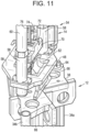
- the upper collet housings 58 are each mounted in additional holes in the baseplate 56 and extend below the baseplate 56 and are adapted to be received in corresponding holes 66 (as shown in Figures 11-13 ) in the top plate 38 of the blade guide tool 12.
- a mounting structure 68 is mounted to the baseplate 56 adjacent to the opening 62 and includes a handle engagement bracket 70 mounted thereto.
- the handle engagement bracket 70 includes a slot 72 for receiving the handle 64 of the blade guide tool 12 and also defines a cable guide 74 for receiving and guiding a cable 76 there through.
- the cable 76 is attached to a slider 80 which supports an engagement hook 82 and pneumatic hook actuator assembly 84.
- the slider 80 is engageable with the inner rails 36a, 36b to traverse along the length of the inner rails 36a, 36b.
- the slider 80 can be lowered by the cable 76 along the inner rails 36a, 36b and can bring the hook 82 into engagement with an upper handle 20A of the control rod 20.
- the hook 82 can be pneumatically engaged by the cylinder of the hook actuator assembly 84 and the cable 76 can be utilized to raise the control rod 20.
- a pair of downwardly protruding guide plates 88 extend below the baseplate 56 of the blade exchange tool 14 to guide the slider 80 into its transition between the inner rails 36a, 36b.
- each of the upper collet housings 58 include an upper collet 90 disposed within the housing and engaged with the air cylinder 60 for activation.
- the upper collets 90 are engageable with the upper end of the fuel support grapple actuator rods 44 to latch onto the actuating rods 44 and to press the actuating rods 44 downward into the lower collet housings 30 as shown sequentially in Figures 17-19 , for engaging the lower collets 32 to spread laterally outward to engage an inwardly extending lip 92 surrounding the fuel bundle pockets 26 of the fuel support 16 by a hook portion 94 on the ends of each collet section 32.
- the lower collets 32 are engageable with the fuel support 16 in order to lift the fuel support 16 out of the core along with the control rod 20.
- the core support 18 includes a core support pin 52 which causes the core support pin actuating rod 48 to move upward in order to cause activation of an air switch actuator assembly 54 of the blade exchange tool 14.
- the air switch actuator assembly 54 includes a housing 100 which supports a core support pin flag 102.
- the core support pin flag 102 is engaged with an upper end of the core support pin actuating rod 48 which presses the core support pin flag 102 upward when the core support pin actuating rod 48 is pushed upward by engagement with the core support pin 52 when the blade guide tool is properly engaged with the fuel support 16.
- an air switch 104 is mounted to the air switch actuator assembly 54 and includes a cam follower 106 and switch arm 107 engaged with a cam surface 108 on the core support pin flag 102.
- a blade guide hook 110 is mounted on the mounting structure 68 for securing the handle engagement bracket 70 to the handle 64 of the blade guide tool 12 to prevent separation there from.
- the blade guide hook 110 can be actuated manually or by a pneumatic actuator.
- the cylinder of the hook actuator assembly 84 can be activated to engage the hook 82 to the handle 20a.
- the blade guide and exchange tool 10 is comprised of two separate tools, the blade guide tool 12 and the blade exchange tool 14 which when combined, form the blade guide and exchange tool 10.
- the blade guide tool 12 With two of the fuel bundles removed, the blade guide tool 12 seats on the fuel support 16 and extends up through a top guide of a cell.
- the blade guide tool 12 is used to support a control rod 20 while moving fuel in and out of the cell.
- the blade guide tool 12 contains the fuel support grapple lower collets 32 that are actuated via the actuating rods 44 that extends from the collets 32 to the top of the blade guide tool 12.
- the actuating rods 44 are actuated by the blade exchange tool 14 after it is mated to the blade guide tool 12.
- the blade guide tool 12 also contains a spring-loaded pin actuating rod 48 that is in line with the core support alignment pin 52 and extends the full length of the blade guide tool 12.
- the pin actuating rod 48 is used to operate the air switch 104 of the blade exchange tool 14 to control airflow to the fuel support grapple collets 32 when the pin actuating rod 48 is either engaged, or not engaged, on the alignment pin 52.
- the blade guide tool 12 is installed first into the cell of the control rod 20 to be removed.
- the blade guide tool 12 supports the inserted control rod 20 as the remaining two fuel bundles are removed from the cell and supports the control rod 20 as it is fully retracted to its back-seated position.
- the blade exchange tool 14 is connected to an air supply hose and to a hoist via a 12-foot cable attached to the control rod grapple 20a.
- the blade exchange tool 14 is then lowered onto the blade guide tool 12.
- the blade exchange tool 14 contains a connecting hook 110 to join the blade guide tool 12 and the blade exchange tools 14 together, and a pair of air actuators 60 for the fuel support grapple collets 32.
- the tool 10 When the blade guide tool 12 and the blade exchange tool 14 are connected and grappled together, the tool 10 is referred to as the blade guide and exchange tool 10.
- the upper collets 58 lock onto the fuel support grapple actuating rods 44 of the blade guide tool 12 to guide the blade exchange tool 14 as it is lowered onto the control rod handle 20a. Air is supplied to the tool 14 to grapple the control rod 20 via hook 82 and fuel support 16 via the lower collets 32.
- the control rod 20 is then lifted into the tool 10 until the control rod slider 80 contacts the top and of the blade guide and exchange tool 10 at which point the blade guide and exchange tool 10, along with the control rod 20 and fuel support 16 are also lifted.
- the tool 10, control rod 20, and fuel support 16 are removed from the cell and transported to the exchange area.
- the control rod 20 is lowered and seated in an exchange container.
- the fuel support grapple collets 32 will not release since the tool 10 is not engaged with the core support alignment pin 52 and therefore the air switch 104 is closed preventing airflow to the retract side of the fuel support grapple collets 32.
- the fuel support 16 can now be lifted off the spent control rod 20 and placed onto a new control rod 20 located in another storage container.
- the new control rod 20 is grappled by the hook 82, lifted into the tool 10, and then reinstalled in the cell. After the fuel support 16 and control rod 20 are seated in the guide tube, both are released and the blade exchange tool 14 can be lifted off the blade guide tool 12.
- the blade guide tool 12 remains to allow for blade insertion and loading of two fuel bundles.
- the core support pin actuating rod 48 is engaged with the core support pin 52 to allow the air release to the air cylinders 60 of the upper collets 90 via the air switch actuator assembly 54. Accordingly, the blade guide tool 12 is then removed via release of the collets 32 and so additional fuel bundles can be loaded.
- the blade guide function and the control rod exchange function are combined into one tool therefore two incore alteration steps, the need to remove and reinstall a blade guide.
- the present disclosure also provides verification checks (315 pin engagement and fuel support grappling) that are located at the top of the tool (as opposed to other tools which have verifications at the bottom of the tool) and can easily be viewed and verified by an underwater camera.
- verification checks (315 pin engagement and fuel support grappling) that are located at the top of the tool (as opposed to other tools which have verifications at the bottom of the tool) and can easily be viewed and verified by an underwater camera.
- the ease of verification checks saves considerable time in the overall exchange process.
- the grid guide is a separate tool used with other control rod exchange tools but is not needed with the blade guide and exchange tool of the present disclosure, as the blade guide portion of the tool serves the grid guide function. This eliminates setup and installation of this tool and therefore saves time and radiation exposure to the worker.
Description
- The present application claims priority to
U.S. Application No. 16/412,979, filed May 15, 2019 - The present disclosure relates to a boiling water reactor blade guide and exchange tool.
- This section provides background information related to the present disclosure which is not necessarily prior art.
- The control rods in a boiling water reactor contain an absorbent material that when positioned in the reactor core can be used to slow the fission rate of the nuclear fuel. However, the absorbent material is subject to degradation after extended use. Therefore, it is periodically necessary to replace the control rods. In order to remove a control rod from its core location, or cell, it is necessary to provide access to the control rod by removing the fuel and the fuel support associated with the control rod to be removed. It is also necessary to disconnect the control rod from its drive. Tools commonly used to remove the fuel include the fuel grapple and a blade guide which supports the control rod while two of the four fuel bundles are being removed. A control rod unlatching tool is used to disconnect the control rod from its drive. Tools used to remove and/or replace the control rods include a grapple for lifting the fuel support and a grapple for lifting the control rod. These can be separate tools or their functions combined into one tool. The fuel support and control rod are lifted out of their cell and a new control rod and the same fuel support are placed back in the cell. The new control rod is reconnected to the drive without need of tools. A blade guide is placed in the cell and the control rod is then inserted to allow for fuel installation. Two fuel bundles are then placed in the cells next to the blade guide. The blade guide is then removed and two additional fuel bundles are installed in the locations of the vacated blade guide, to complete the control rod and fuel replacement for that cell.
- Gen Electric (
JP H0772289 A - Westinghouse Electric Corp (
US 2014/205050 A1 ) discloses a fuel assembly handling tool that can be lowered onto the top nozzle of a fuel assembly, positively latch the top nozzle, unlatch from the top nozzle, and be raised off the top nozzle of the fuel assembly. The tool head, that interfaces with the top nozzle has load bearing grippers that latch onto the fuel assembly, that are located in a storage position up within the tool while the tool is lowered onto the fuel assembly. - This section provides a general summary of the disclosure, and is not a comprehensive disclosure of its full scope or all of its features.
- According to the invention, there is provided a combined blade guide and exchange tool as defined by
independent claim 1, and a method of removing a control rod and fuel support from a cell of a boiling water reactor as defined by independent claim 8. Further advantageous features of the invention are defined by the dependent claims. - The present disclosure provides a blade guide and exchange tool which is comprised of two separate tools: the blade guide tool and the blade exchange tool which, when combined, form the blade guide and exchange tool. The blade guide tool seats on the fuel support and extends up through the top guide. The blade guide tool is used to support a control rod while moving fuel in and out of the cell. In addition to the guiding features, the blade guide tool contains the fuel support grapple that is actuated via a rod that extends from the grapple to the top of the blade guide tool. The rod is actuated by the blade exchange tool after it is mated to the blade guide tool. The blade guide tool also contains a spring-loaded extension rod, extending the full length of the tool, that is in line with the core support alignment pin commonly called the 315 pin. When the blade guide seats on the fuel support, this extension rod contacts the 315 pin causing the rod to lift. The lifted rod engages a mechanism on the blade exchange tool which opens two air switches. The open air switches allow airflow to the fuel support grapple cylinders therefore allowing for operation of the fuel support grapple. When the fuel support is lifted off the core plate, the spring-loaded extension rod loses contact with the 315 pin which causes it to move down. When the rod is down, it disengages from the mechanism on the blade exchange tool which causes the valves to close and disables actuation of the fuel support grapple.
- Initially, two of the four fuel bundles in the cell of the control rod to be replaced are removed using the fuel grapple. The blade guide is then installed in the removed fuel locations to support the inserted control rod as the remaining two fuel bundles are removed from the cell. The control rod can now be fully retracted to its back-seated position, as there is no fuel remaining in the cell. The blade exchange tool is connected to an air supply hose and to a hoist via a 12-foot (3.66 m) cable attached to the control rod grapple. The blade exchange tool is then lowered onto the blade guide tool and connected to it. The blade exchange tool contains a handle latch, fuel support grapple actuators, a control rod grapple, and air switches to control airflow to the fuel support grapple actuators. When the blade guide and blade exchange tools are connected and grappled together, the tool is referred to as the blade guide and exchange tool.
- When the connection of the two tools is made, the control rod grapple engages the center tubes of the blade guide tool, which act as a guide for the grapple to keep it centered in the cell as it is lowered approximately 10 feet to engage the control rod handle. With the blade guide seated on the fuel support and on the 315 pin, the control rod grapple is lowered onto the control rod handle. Air is then supplied to the tool to grapple the control rod and fuel support. The hoist is raised to lift the control rod into the tool until the control rod grapple contacts the underside of the blade guide handle. At this point, raising the hoist further will also lift the blade guide, the exchange tool, and the fuel support. The tool and components are lifted out of the cell, via the hoist, and transported to the exchange area. The control rod is then lowered and seated in the exchange container. Air is supplied to the disengage (or open) side of the exchange tool to disengage the control rod grapple. The control rod grapple air supply (engage and disengage) bypass the air switches and therefore will always operate regardless of being on or off the 315 pin. The disengage action will not actuate the fuel support grapple since the blade guide tool is not engaged on the 315 pin. When off the 315 pin, the air switch is closed preventing airflow to the fuel support grapple. At this point, the control rod is seated in the container, the control rod grapple is disengaged from the control rod handle, and the fuel support is still grappled by the tool. The fuel support can now be lifted off the spent control rod, by raising the hoist, and placed onto a new control rod located in another storage container. The new control rod is grappled by the hook, lifted into the tool, and then out of the storage container. The control rod and fuel support are transported back to the core and reinstalled in the cell. After the fuel support and control rod are seated in the guide tube and the fuel support has engaged the 315 pin, both the fuel support and control rod can be released. The blade exchange tool can be lifted off the blade guide tool. The blade guide tool remains to allow for blade insertion and loading of two fuel bundles into the cell. After this step, the blade guide is removed via the fuel grapple, and two additional fuel bundles can be loaded in its place.
- According to an aspect of the present disclosure, a combined blade guide and exchange tool includes a blade guide tool having a lower end and an upper end and a plurality of frame rails supporting a pair of collet housings at a lower end of the blade guide tool. A pair of fuel support grapple actuating rods are supported between the plurality of frame rails and have a first end engaging a pair of collets within the pair of collet housings and a second end disposed at the upper end of the blade guide tool. A blade exchange tool is releasably mounted to the upper end of the blade guide tool and includes a pair of upper collets for engaging the pair of fuel support grapple actuating rods. The blade exchange tool further includes a trolley and hook assembly attached to a cable guided by the blade exchange tool and adapted for engaging and lifting a control rod.
- Further areas of applicability will become apparent from the description provided herein. The description and specific examples in this summary are intended for purposes of illustration only and are not intended to limit the scope of the present disclosure.
- The drawings described herein are for illustrative purposes only of selected embodiments and not all possible implementations, and are not intended to limit the scope of the present disclosure.
-
Figure 1 is a perspective view of a blade guide and exchange tool assembled on a fuel support and having a control rod fully retracted according to the principles of the present disclosure; -
Figure 2 is a perspective view of the blade guide and exchange tool assembled on a fuel support and having the control rod fully extended; -
Figure 3A is a close-up perspective view of the bottom of the blade guide and exchange tool assembled on a fuel support; -
Figure 3B is a close-up perspective view of the top of the blade guide and exchange tool; -
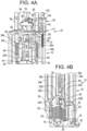
Figure 4A is a close-up perspective view of the top of the blade guide and exchange tool with the hook being engaged to the handle of the control rod in its extended position; -
Figure 4B is a close-up perspective view of the bottom of the blade guide and exchange tool with the hook being engaged to the handle of the control rod in its retracted position; -
Figure 5 is a perspective view of the blade guide tool according to the principles of the present disclosure; -
Figure 6 is a partially cutaway view of the top of the blade guide tool according to the principles of the present disclosure; -
Figure 7 is a partially cutaway view of the top of the blade guide tool according to the principles of the present disclosure with the core support pin actuating rod shown in a retracted position; -
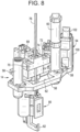
Figure 8 is a front perspective view of the blade exchange tool according to the principles of present disclosure; -
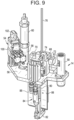
Figure 9 is a rear perspective view of the blade exchange tool shown inFigure 8 ; -
Figure 10 is a front plan view of the blade exchange tool shown inFigure 8 ; -
Figure 11 is a top perspective view showing the blade exchange tool being assembled to the blade guide tool according to the principles of the present disclosure; -
Figure 12 is a side perspective view showing the blade exchange tool being assembled to the blade guide tool according to the principles of the present disclosure; -
Figure 13 is a side perspective view showing the blade exchange tool fully assembled to the blade guide tool according to the principles of the present disclosure; -
Figure 14 is a top perspective view showing the clearance for the slider of the blade exchange tool being assembled to the blade guide tool according to the principles of the present disclosure; -
Figure 15 is a side plan view of the top of the blade guide and exchange tool; -
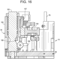
Figure 16 is a detailed view of the air switch actuator assembly and the air switch of the blade guide and exchange tool; -
Figure 17 is a partial cutaway view of the collet housing and collet assembly used for engaging the fuel support; -
Figure 18 is a partial cutaway view of the collet housing and collet assembly during an engagement of the fuel support; -
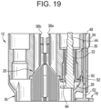
Figure 19 is a partial cutaway view of the collet housing and collet assembly after full engagement of the fuel support; and -
Figure 20 is a cross-sectional view of the upper collet housing according to the principles of the present disclosure. - Corresponding reference numerals indicate corresponding parts throughout the several views of the drawings.
- Example embodiments will now be described more fully with reference to the accompanying drawings.
- Example embodiments are provided so that this disclosure will be thorough, and will fully convey the scope to those who are skilled in the art. Numerous specific details are set forth such as examples of specific components, devices, and methods, to provide a thorough understanding of embodiments of the present disclosure. It will be apparent to those skilled in the art that specific details need not be employed, that example embodiments may be embodied in many different forms and that neither should be construed to limit the scope of the disclosure. In some example embodiments, well-known processes, well-known device structures, and well-known technologies are not described in detail.
- The terminology used herein is for the purpose of describing particular example embodiments only and is not intended to be limiting. As used herein, the singular forms "a," "an," and "the" may be intended to include the plural forms as well, unless the context clearly indicates otherwise. The terms "comprises," "comprising," "including," and "having," are inclusive and therefore specify the presence of stated features, integers, steps, operations, elements, and/or components, but do not preclude the presence or addition of one or more other features, integers, steps, operations, elements, components, and/or groups thereof. The method steps, processes, and operations described herein are not to be construed as necessarily requiring their performance in the particular order discussed or illustrated, unless specifically identified as an order of performance. It is also to be understood that additional or alternative steps may be employed.
- When an element or layer is referred to as being "on," "engaged to," "connected to," or "coupled to" another element or layer, it may be directly on, engaged, connected or coupled to the other element or layer, or intervening elements or layers may be present. In contrast, when an element is referred to as being "directly on," "directly engaged to," "directly connected to," or "directly coupled to" another element or layer, there may be no intervening elements or layers present. Other words used to describe the relationship between elements should be interpreted in a like fashion (e.g., "between" versus "directly between," "adjacent" versus "directly adjacent," etc.). As used herein, the term "and/or" includes any and all combinations of one or more of the associated listed items.
- Although the terms first, second, third, etc. may be used herein to describe various elements, components, regions, layers and/or sections, these elements, components, regions, layers and/or sections should not be limited by these terms. These terms may be only used to distinguish one element, component, region, layer, or section from another region, layer, or section. Terms such as "first," "second," and other numerical terms when used herein do not imply a sequence or order unless clearly indicated by the context. Thus, a first element, component, region, layer, or section discussed below could be termed a second element, component, region, layer, or section without departing from the teachings of the example embodiments.
- Spatially relative terms, such as "inner," "outer," "beneath," "below," "lower," "above," "upper," and the like, may be used herein for ease of description to describe one element or feature's relationship to another element(s) or feature(s) as illustrated in the figures. Spatially relative terms may be intended to encompass different orientations of the device in use or operation in addition to the orientation depicted in the figures. For example, if the device in the figures is turned over, elements described as "below" or "beneath" other elements or features would then be oriented "above" the other elements or features. Thus, the example term "below" can encompass both an orientation of above and below. The device may be otherwise oriented (rotated 90 degrees or at other orientations) and the spatially relative descriptors used herein interpreted accordingly.
- With reference to
Figures 1-4 , a blade guide andexchange tool 10 is shown including ablade guide tool 12 and ablade exchange tool 14 removably assembled to theblade guide tool 12. InFigures 1, 2 ,3A and4B , a base 12a of theblade guide 12 is shown engaged with afuel support 16 which is disposed next to acore support 18. As best shown inFigures 3A ,3B , acontrol rod 20 includes a plurality ofblades 22A-22D formed in a cruciform shape and extending through acruciform passage 24 in thefuel support 16. As is known in the art, thecontrol rod 20 contains an absorbent material that when positioned in the reactor core can be used to slow the fission rate of the nuclear fuel. Thefuel support 16 includes fourpockets 26 each for receiving the base of a fuel bundle (not shown). - The base 12a of the
blade guide tool 12 includes a pair ofcollet housings 30 which each house acollet assembly 32, best shown inFigures 17-19 . The pair ofcollet housings 30 are connected to a pair ofouter frame rails inner frame rails top plate 38 is attached to the tops of theouter frame rails inner frame rails brace plates 40 are disposed between corresponding ones of theouter frame rails inner frame rails brace plates 40 each include aguide hole 42 extending there through. A pair of fuel support grappleactuating rods 44 extend through each of the guide holes 42 of thebrace plates 40 and have a bottom end that engages acollet assembly 32 within the pair ofcollet housings 30 and have a top end that is disposed in acorresponding guide housing 46 extending below thetop plate 38. Aspring 47 is disposed in theguide housing 46 for biasing the fuel support grappleactuating rods 44 in an upward direction. - A core support
pin actuating rod 48 is disposed within, and extends along a length of one of theouter frame rails 34a. The core supportpin actuating rod 48 has a lower end that is guided within aguide housing 50 and engaged by a core support pin 52 (best shown inFigures 17-19 ) when theblade guide tool 12 is properly seated in thefuel support 16. Thecore support pin 52 extends upward from thecore support 18 and when engaged by the core supportpin actuating rod 48, causes the core supportpin actuating rod 48 to move upward in order to cause activation of an airswitch actuator assembly 54 of theblade exchange tool 14, as will be described in further detail herein. - As best shown in
Figure 8 , theblade exchange tool 14 includes abase plate 56 to which the airswitch actuator assembly 54 is mounted along with a pair ofupper collet housings 58. A pair ofair cylinders 60 are mounted on each of thecollet housings 58. Thebaseplate 56 includes an opening 62 (best shown inFigure 8 ) therein for receiving aU-shaped handle 64 extending from thetop plate 38 of theblade guide tool 12. Theupper collet housings 58 are each mounted in additional holes in thebaseplate 56 and extend below thebaseplate 56 and are adapted to be received in corresponding holes 66 (as shown inFigures 11-13 ) in thetop plate 38 of theblade guide tool 12. - As shown in
Figures 8 and9 , a mountingstructure 68 is mounted to thebaseplate 56 adjacent to theopening 62 and includes ahandle engagement bracket 70 mounted thereto. Thehandle engagement bracket 70 includes aslot 72 for receiving thehandle 64 of theblade guide tool 12 and also defines acable guide 74 for receiving and guiding acable 76 there through. Thecable 76 is attached to aslider 80 which supports anengagement hook 82 and pneumatichook actuator assembly 84. Theslider 80 is engageable with theinner rails inner rails slider 80 can be lowered by thecable 76 along theinner rails hook 82 into engagement with anupper handle 20A of thecontrol rod 20. Thehook 82 can be pneumatically engaged by the cylinder of thehook actuator assembly 84 and thecable 76 can be utilized to raise thecontrol rod 20. As best shown inFigure 9 , a pair of downwardly protrudingguide plates 88 extend below thebaseplate 56 of theblade exchange tool 14 to guide theslider 80 into its transition between theinner rails - As best shown in the partially cutaway view of
Figure 10 , each of theupper collet housings 58 include anupper collet 90 disposed within the housing and engaged with theair cylinder 60 for activation. Theupper collets 90 are engageable with the upper end of the fuel support grappleactuator rods 44 to latch onto theactuating rods 44 and to press the actuatingrods 44 downward into thelower collet housings 30 as shown sequentially inFigures 17-19 , for engaging thelower collets 32 to spread laterally outward to engage an inwardly extendinglip 92 surrounding the fuel bundle pockets 26 of thefuel support 16 by ahook portion 94 on the ends of eachcollet section 32. Accordingly, thelower collets 32 are engageable with thefuel support 16 in order to lift thefuel support 16 out of the core along with thecontrol rod 20. - As mentioned above, the
core support 18 includes acore support pin 52 which causes the core supportpin actuating rod 48 to move upward in order to cause activation of an airswitch actuator assembly 54 of theblade exchange tool 14. The airswitch actuator assembly 54 includes ahousing 100 which supports a coresupport pin flag 102. The coresupport pin flag 102 is engaged with an upper end of the core supportpin actuating rod 48 which presses the coresupport pin flag 102 upward when the core supportpin actuating rod 48 is pushed upward by engagement with thecore support pin 52 when the blade guide tool is properly engaged with thefuel support 16. As shown inFigure 16 , anair switch 104 is mounted to the airswitch actuator assembly 54 and includes acam follower 106 andswitch arm 107 engaged with acam surface 108 on the coresupport pin flag 102. As the coresupport pin flag 102 is pushed upward, theswitch arm 107 of theair switch 104 is actuated to allow delivery of pneumatic air pressure to a latch that latches theblade exchange tool 14 to theblade guide tool 12 and, when not actuated, to prevent delivery of pneumatic air pressure to a release side of thecollet air cylinders 60. As best shown inFigure 10 , ablade guide hook 110 is mounted on the mountingstructure 68 for securing thehandle engagement bracket 70 to thehandle 64 of theblade guide tool 12 to prevent separation there from. Theblade guide hook 110 can be actuated manually or by a pneumatic actuator. - When the
cable 76 is lowered to allow theslider 80 andhook 82 to be positioned relative to the handle 20a of the core 20, the cylinder of thehook actuator assembly 84 can be activated to engage thehook 82 to the handle 20a. - During operation, the blade guide and
exchange tool 10 is comprised of two separate tools, theblade guide tool 12 and theblade exchange tool 14 which when combined, form the blade guide andexchange tool 10. With two of the fuel bundles removed, theblade guide tool 12 seats on thefuel support 16 and extends up through a top guide of a cell. Theblade guide tool 12 is used to support acontrol rod 20 while moving fuel in and out of the cell. In addition to the guiding features, theblade guide tool 12 contains the fuel support grapplelower collets 32 that are actuated via theactuating rods 44 that extends from thecollets 32 to the top of theblade guide tool 12. The actuatingrods 44 are actuated by theblade exchange tool 14 after it is mated to theblade guide tool 12. Theblade guide tool 12 also contains a spring-loadedpin actuating rod 48 that is in line with the coresupport alignment pin 52 and extends the full length of theblade guide tool 12. Thepin actuating rod 48 is used to operate theair switch 104 of theblade exchange tool 14 to control airflow to the fuel support grapplecollets 32 when thepin actuating rod 48 is either engaged, or not engaged, on thealignment pin 52. - The
blade guide tool 12 is installed first into the cell of thecontrol rod 20 to be removed. Theblade guide tool 12 supports the insertedcontrol rod 20 as the remaining two fuel bundles are removed from the cell and supports thecontrol rod 20 as it is fully retracted to its back-seated position. Theblade exchange tool 14 is connected to an air supply hose and to a hoist via a 12-foot cable attached to the control rod grapple 20a. Theblade exchange tool 14 is then lowered onto theblade guide tool 12. Theblade exchange tool 14 contains a connectinghook 110 to join theblade guide tool 12 and theblade exchange tools 14 together, and a pair ofair actuators 60 for the fuel support grapplecollets 32. When theblade guide tool 12 and theblade exchange tool 14 are connected and grappled together, thetool 10 is referred to as the blade guide andexchange tool 10. After connection of the twotools upper collets 58 lock onto the fuel support grappleactuating rods 44 of theblade guide tool 12 to guide theblade exchange tool 14 as it is lowered onto the control rod handle 20a. Air is supplied to thetool 14 to grapple thecontrol rod 20 viahook 82 andfuel support 16 via thelower collets 32. Thecontrol rod 20 is then lifted into thetool 10 until thecontrol rod slider 80 contacts the top and of the blade guide andexchange tool 10 at which point the blade guide andexchange tool 10, along with thecontrol rod 20 andfuel support 16 are also lifted. - The
tool 10,control rod 20, andfuel support 16 are removed from the cell and transported to the exchange area. Thecontrol rod 20 is lowered and seated in an exchange container. The fuel support grapplecollets 32 will not release since thetool 10 is not engaged with the coresupport alignment pin 52 and therefore theair switch 104 is closed preventing airflow to the retract side of the fuel support grapplecollets 32. Thefuel support 16 can now be lifted off the spentcontrol rod 20 and placed onto anew control rod 20 located in another storage container. Thenew control rod 20 is grappled by thehook 82, lifted into thetool 10, and then reinstalled in the cell. After thefuel support 16 andcontrol rod 20 are seated in the guide tube, both are released and theblade exchange tool 14 can be lifted off theblade guide tool 12. Theblade guide tool 12 remains to allow for blade insertion and loading of two fuel bundles. The core supportpin actuating rod 48 is engaged with thecore support pin 52 to allow the air release to theair cylinders 60 of theupper collets 90 via the airswitch actuator assembly 54. Accordingly, theblade guide tool 12 is then removed via release of thecollets 32 and so additional fuel bundles can be loaded. - With the present disclosure, the blade guide function and the control rod exchange function are combined into one tool therefore two incore alteration steps, the need to remove and reinstall a blade guide.
- The present disclosure also provides verification checks (315 pin engagement and fuel support grappling) that are located at the top of the tool (as opposed to other tools which have verifications at the bottom of the tool) and can easily be viewed and verified by an underwater camera. The ease of verification checks saves considerable time in the overall exchange process.
- The grid guide is a separate tool used with other control rod exchange tools but is not needed with the blade guide and exchange tool of the present disclosure, as the blade guide portion of the tool serves the grid guide function. This eliminates setup and installation of this tool and therefore saves time and radiation exposure to the worker.
- The foregoing description of the embodiments has been provided for purposes of illustration and description. It is not intended to be exhaustive or to limit the disclosure. Individual elements or features of a particular embodiment are generally not limited to that particular embodiment, but, where applicable, are interchangeable and can be used in a selected embodiment, even if not specifically shown or described. The same may also be varied in many ways. The invention is defined in the appended claims.
Claims (14)
- A combined blade guide and exchange tool (10), comprising:a blade guide tool (12) having a lower end and an upper end and a plurality of frame rails (34a, 34b, 36a, 36b) supporting a pair of collet housings (30) at a lower end of the blade guide tool (12), a pair of fuel support grapple actuating rods (44) are supported between the plurality of frame rails and having a first end engaging a pair of collets within the pair of collet housings (30) and having a second end disposed at the upper end of the blade guide tool (12); anda blade exchange tool (14) releasably mounted to the upper end of the blade guide tool (12) and including a pair of upper collets (90) for engaging the pair of fuel support grapple actuating rods (44), the blade exchange tool further including a slider (80) and hook assembly (82) attached to a cable (76) guided by the blade exchange tool and adapted for engaging and lifting a control rod (20).
- The combined blade guide and exchange tool according to claim 1, further comprising:
a pair of air cylinders (60) connected to respective ones of the pair of upper collets (90). - The combined blade guide and exchange tool according to claim 2, further comprising:
a fuel support pin actuating rod (48) adapted to engage a pin (52) on a core support (18), the fuel support pin actuating rod (48) is engageable by an air switch actuating assembly (54) of the blade exchange tool, the air switch actuating assembly (54) being engageable with an air switch (104) of the blade exchange tool, the air switch (104) being activated to prevent airflow to the retract side of the air cylinders (60) of the pair of upper collets (90). - The combined blade guide and exchange tool according to claim 1, wherein the slider (80) and hook assembly (82) includes a hook actuator cylinder (84).
- The combined blade guide and exchange tool according to claim 1, wherein the blade exchange tool (14) includes a connecting device for releasably connecting the blade exchange tool (14) to the blade guide tool (12).
- The combined blade guide and exchange tool according to claim 1, wherein the blade guide tool (12) includes a top plate (38) at the upper end of the blade guide tool (12) and the blade exchange tool (14) includes a base plate (56) that is supported on top of the top plate (38) when the blade exchange tool (14) is engaged with the blade guide tool (12).
- The combined blade guide and exchange tool according to claim 1, wherein the pair of upper collets (90) are each disposed within a respective upper collet housing (58).
- A method of removing a control rod (20) and fuel support (16) from a cell of a boiling water reactor, comprising:inserting into the cell a blade guide tool (12) having a pair of collet housings (30) at a lower end of the blade guide tool (12) so that the pair of collet housings (30) are received in respective fuel bundle pockets (26) in the fuel support (16), the blade guide tool (12) including a pair of fuel support grapple actuating rods (44) each including a first end engaging a respective one of a pair of collets (32) within the pair of collet housings (30) and having a second end disposed at an upper end of the blade guide tool (12);assembling a blade exchange tool (14) to the upper end of the blade guide tool (12), the blade exchange tool (14) including a pair of upper collets (90) for engaging the pair of fuel support grapple actuating rods (44), the blade exchange tool (14) further including a slider (80) and hook assembly (82) attached to a cable (76) guided by the blade exchange tool;actuating the pair of upper collets (90) to engage the pair of lower collets (32) via advancement of the fuel support grapple actuating rods (44) and causing the pair of lower collets (32) to engage the fuel bundle pockets (26) in the fuel support (16); andengaging the hook assembly (82) to a control rod (20) and lifting the blade guide tool (12), the blade exchange tool (14), the control rod (20) and the fuel support (16) from the cell.
- The method according to claim 8, wherein a pair of air cylinders (60) are connected to respective ones of the pair of upper collets (90) and the actuating the pair of upper collets (90) includes activation of the pair of air cylinders (60).
- The method according to claim 9, wherein the inserting includes engaging a fuel support pin actuating rod (48) to a pin (52) on a core support (18), the fuel support pin actuating rod (48) is engageable by an air switch actuating assembly (54) of the blade exchange tool (14), the air switch actuating assembly (54) being engageable with an air switch (104) of the blade exchange tool (14), the air switch (104) being activated to prevent airflow to a retract side of the air cylinders (60) of the pair of upper collets (90).
- The method according to claim 8, wherein the slider (80) and hook assembly (82) includes a hook actuator cylinder (84) and the engaging the hook assembly (82) to a control rod (20) includes actuating the hook actuator cylinder (84).
- The method according to claim 8, wherein the assembling includes the blade exchange tool (14) releasably connecting the blade exchange tool (14) to the blade guide tool (12).
- The method according to claim 8, wherein the assembling includes the blade guide tool (12) having a top plate (38) at the upper end of the blade guide tool (12) and the blade exchange tool (14) includes a base plate (56) that is supported on top of the top plate (38) when the blade exchange tool (14) is engaged with the blade guide tool (12).
- The method according to claim 8, wherein the pair of upper collets (90) are each disposed within a respective upper collet housing (58).
Applications Claiming Priority (2)
| Application Number | Priority Date | Filing Date | Title |
|---|---|---|---|
| US16/412,979 US11348700B2 (en) | 2019-05-15 | 2019-05-15 | Boiling water reactor blade guide and exchange tool |
| PCT/US2020/030730 WO2020231639A1 (en) | 2019-05-15 | 2020-04-30 | Boiling water reactor blade guide and exchange tool |
Publications (2)
| Publication Number | Publication Date |
|---|---|
| EP3970165A1 EP3970165A1 (en) | 2022-03-23 |
| EP3970165B1 true EP3970165B1 (en) | 2023-05-31 |
Family
ID=70802930
Family Applications (1)
| Application Number | Title | Priority Date | Filing Date |
|---|---|---|---|
| EP20727761.7A Active EP3970165B1 (en) | 2019-05-15 | 2020-04-30 | Boiling water reactor blade guide and exchange tool |
Country Status (6)
| Country | Link |
|---|---|
| US (2) | US11348700B2 (en) |
| EP (1) | EP3970165B1 (en) |
| CA (1) | CA3139442C (en) |
| ES (1) | ES2949678T3 (en) |
| MX (1) | MX2021013598A (en) |
| WO (1) | WO2020231639A1 (en) |
Family Cites Families (5)
| Publication number | Priority date | Publication date | Assignee | Title |
|---|---|---|---|---|
| US5473645A (en) | 1993-05-21 | 1995-12-05 | General Electric Company | Fuel support and control rod storage rack |
| US6047037A (en) | 1997-05-19 | 2000-04-04 | Combustion Engineering, Inc. | Multi-lift tool and method for moving control rods in a nuclear reactor |
| DE19751688C1 (en) | 1997-11-21 | 1999-08-19 | Siemens Ag | Adapter for a shortened fuel rod of a nuclear reactor fuel assembly and method for inserting or removing fuel rods |
| US8934601B2 (en) * | 2011-09-30 | 2015-01-13 | Ge-Hitachi Nuclear Energy Americas Llc | Method and apparatus for a BWR control rod handling grapple |
| US9852821B2 (en) | 2013-01-24 | 2017-12-26 | Westinghouse Electric Company Llc | Nuclear fuel assembly handling apparatus |
-
2019
- 2019-05-15 US US16/412,979 patent/US11348700B2/en active Active
-
2020
- 2020-04-30 WO PCT/US2020/030730 patent/WO2020231639A1/en unknown
- 2020-04-30 ES ES20727761T patent/ES2949678T3/en active Active
- 2020-04-30 CA CA3139442A patent/CA3139442C/en active Active
- 2020-04-30 MX MX2021013598A patent/MX2021013598A/en unknown
- 2020-04-30 EP EP20727761.7A patent/EP3970165B1/en active Active
-
2022
- 2022-04-07 US US17/715,347 patent/US11749416B2/en active Active
Also Published As
| Publication number | Publication date |
|---|---|
| US11749416B2 (en) | 2023-09-05 |
| EP3970165A1 (en) | 2022-03-23 |
| US11348700B2 (en) | 2022-05-31 |
| US20220270771A1 (en) | 2022-08-25 |
| MX2021013598A (en) | 2022-02-23 |
| ES2949678T3 (en) | 2023-10-02 |
| JP2022532309A (en) | 2022-07-14 |
| CA3139442C (en) | 2024-04-16 |
| WO2020231639A1 (en) | 2020-11-19 |
| CA3139442A1 (en) | 2020-11-19 |
| US20200365288A1 (en) | 2020-11-19 |
Similar Documents
| Publication | Publication Date | Title |
|---|---|---|
| US5377239A (en) | BWR control rod handling tooling & method | |
| JPS6123519B2 (en) | ||
| RU2338813C2 (en) | Arm for connectors of electrolytic cells designed for production of aluminium | |
| EP3970165B1 (en) | Boiling water reactor blade guide and exchange tool | |
| JPS582633B2 (en) | Gripping device for fuel assembly with guide thimble for nuclear reactor | |
| JP7482898B2 (en) | Boiling Water Reactor Blade Guide Replacement Tool | |
| US8934601B2 (en) | Method and apparatus for a BWR control rod handling grapple | |
| KR102218335B1 (en) | Nuclear fuel assembly handling apparatus | |
| US6556641B2 (en) | Apparatus and method for handling reactor-internal equipments | |
| EP2071582B1 (en) | Channel-Lifting Tool and Method | |
| JP2002243889A (en) | Control rod handling device | |
| CN111986826A (en) | Gripping device of resistance plug assembly | |
| JP2839776B2 (en) | Fuel channel attachment / detachment machine | |
| CN116153540A (en) | Clamping device | |
| CN116913564A (en) | Nuclear power plant inner plug-in unit operation sleeve device and inner plug-in unit loading and reloading method | |
| JP2505567B2 (en) | Gripper for gripping insert in fuel assembly and handling tool including the same | |
| JPH06265687A (en) | Gripper device for fuel container basket | |
| JPWO2020231639A5 (en) | ||
| JPS6197595A (en) | Tool for treating storage rack of nuclear reactor |
Legal Events
| Date | Code | Title | Description |
|---|---|---|---|
| STAA | Information on the status of an ep patent application or granted ep patent |
Free format text: STATUS: UNKNOWN |
|
| STAA | Information on the status of an ep patent application or granted ep patent |
Free format text: STATUS: THE INTERNATIONAL PUBLICATION HAS BEEN MADE |
|
| PUAI | Public reference made under article 153(3) epc to a published international application that has entered the european phase |
Free format text: ORIGINAL CODE: 0009012 |
|
| STAA | Information on the status of an ep patent application or granted ep patent |
Free format text: STATUS: REQUEST FOR EXAMINATION WAS MADE |
|
| 17P | Request for examination filed |
Effective date: 20211215 |
|
| AK | Designated contracting states |
Kind code of ref document: A1 Designated state(s): AL AT BE BG CH CY CZ DE DK EE ES FI FR GB GR HR HU IE IS IT LI LT LU LV MC MK MT NL NO PL PT RO RS SE SI SK SM TR |
|
| DAV | Request for validation of the european patent (deleted) | ||
| DAX | Request for extension of the european patent (deleted) | ||
| GRAP | Despatch of communication of intention to grant a patent |
Free format text: ORIGINAL CODE: EPIDOSNIGR1 |
|
| STAA | Information on the status of an ep patent application or granted ep patent |
Free format text: STATUS: GRANT OF PATENT IS INTENDED |
|
| INTG | Intention to grant announced |
Effective date: 20230104 |
|
| GRAS | Grant fee paid |
Free format text: ORIGINAL CODE: EPIDOSNIGR3 |
|
| GRAA | (expected) grant |
Free format text: ORIGINAL CODE: 0009210 |
|
| STAA | Information on the status of an ep patent application or granted ep patent |
Free format text: STATUS: THE PATENT HAS BEEN GRANTED |
|
| AK | Designated contracting states |
Kind code of ref document: B1 Designated state(s): AL AT BE BG CH CY CZ DE DK EE ES FI FR GB GR HR HU IE IS IT LI LT LU LV MC MK MT NL NO PL PT RO RS SE SI SK SM TR |
|
| REG | Reference to a national code |
Ref country code: GB Ref legal event code: FG4D Ref country code: CH Ref legal event code: EP |
|
| REG | Reference to a national code |
Ref country code: AT Ref legal event code: REF Ref document number: 1571443 Country of ref document: AT Kind code of ref document: T Effective date: 20230615 Ref country code: DE Ref legal event code: R096 Ref document number: 602020011344 Country of ref document: DE |
|
| REG | Reference to a national code |
Ref country code: IE Ref legal event code: FG4D |
|
| REG | Reference to a national code |
Ref country code: LT Ref legal event code: MG9D |
|
| REG | Reference to a national code |
Ref country code: ES Ref legal event code: FG2A Ref document number: 2949678 Country of ref document: ES Kind code of ref document: T3 Effective date: 20231002 |
|
| REG | Reference to a national code |
Ref country code: NL Ref legal event code: MP Effective date: 20230531 |
|
| REG | Reference to a national code |
Ref country code: AT Ref legal event code: MK05 Ref document number: 1571443 Country of ref document: AT Kind code of ref document: T Effective date: 20230531 |
|
| PG25 | Lapsed in a contracting state [announced via postgrant information from national office to epo] |
Ref country code: SE Free format text: LAPSE BECAUSE OF FAILURE TO SUBMIT A TRANSLATION OF THE DESCRIPTION OR TO PAY THE FEE WITHIN THE PRESCRIBED TIME-LIMIT Effective date: 20230531 Ref country code: NO Free format text: LAPSE BECAUSE OF FAILURE TO SUBMIT A TRANSLATION OF THE DESCRIPTION OR TO PAY THE FEE WITHIN THE PRESCRIBED TIME-LIMIT Effective date: 20230831 Ref country code: AT Free format text: LAPSE BECAUSE OF FAILURE TO SUBMIT A TRANSLATION OF THE DESCRIPTION OR TO PAY THE FEE WITHIN THE PRESCRIBED TIME-LIMIT Effective date: 20230531 |
|
| PG25 | Lapsed in a contracting state [announced via postgrant information from national office to epo] |
Ref country code: RS Free format text: LAPSE BECAUSE OF FAILURE TO SUBMIT A TRANSLATION OF THE DESCRIPTION OR TO PAY THE FEE WITHIN THE PRESCRIBED TIME-LIMIT Effective date: 20230531 Ref country code: PL Free format text: LAPSE BECAUSE OF FAILURE TO SUBMIT A TRANSLATION OF THE DESCRIPTION OR TO PAY THE FEE WITHIN THE PRESCRIBED TIME-LIMIT Effective date: 20230531 Ref country code: NL Free format text: LAPSE BECAUSE OF FAILURE TO SUBMIT A TRANSLATION OF THE DESCRIPTION OR TO PAY THE FEE WITHIN THE PRESCRIBED TIME-LIMIT Effective date: 20230531 Ref country code: LV Free format text: LAPSE BECAUSE OF FAILURE TO SUBMIT A TRANSLATION OF THE DESCRIPTION OR TO PAY THE FEE WITHIN THE PRESCRIBED TIME-LIMIT Effective date: 20230531 Ref country code: LT Free format text: LAPSE BECAUSE OF FAILURE TO SUBMIT A TRANSLATION OF THE DESCRIPTION OR TO PAY THE FEE WITHIN THE PRESCRIBED TIME-LIMIT Effective date: 20230531 Ref country code: IS Free format text: LAPSE BECAUSE OF FAILURE TO SUBMIT A TRANSLATION OF THE DESCRIPTION OR TO PAY THE FEE WITHIN THE PRESCRIBED TIME-LIMIT Effective date: 20230930 Ref country code: HR Free format text: LAPSE BECAUSE OF FAILURE TO SUBMIT A TRANSLATION OF THE DESCRIPTION OR TO PAY THE FEE WITHIN THE PRESCRIBED TIME-LIMIT Effective date: 20230531 Ref country code: GR Free format text: LAPSE BECAUSE OF FAILURE TO SUBMIT A TRANSLATION OF THE DESCRIPTION OR TO PAY THE FEE WITHIN THE PRESCRIBED TIME-LIMIT Effective date: 20230901 |
|
| PG25 | Lapsed in a contracting state [announced via postgrant information from national office to epo] |
Ref country code: FI Free format text: LAPSE BECAUSE OF FAILURE TO SUBMIT A TRANSLATION OF THE DESCRIPTION OR TO PAY THE FEE WITHIN THE PRESCRIBED TIME-LIMIT Effective date: 20230531 |
|
| PG25 | Lapsed in a contracting state [announced via postgrant information from national office to epo] |
Ref country code: SK Free format text: LAPSE BECAUSE OF FAILURE TO SUBMIT A TRANSLATION OF THE DESCRIPTION OR TO PAY THE FEE WITHIN THE PRESCRIBED TIME-LIMIT Effective date: 20230531 |
|
| PG25 | Lapsed in a contracting state [announced via postgrant information from national office to epo] |
Ref country code: SM Free format text: LAPSE BECAUSE OF FAILURE TO SUBMIT A TRANSLATION OF THE DESCRIPTION OR TO PAY THE FEE WITHIN THE PRESCRIBED TIME-LIMIT Effective date: 20230531 Ref country code: SK Free format text: LAPSE BECAUSE OF FAILURE TO SUBMIT A TRANSLATION OF THE DESCRIPTION OR TO PAY THE FEE WITHIN THE PRESCRIBED TIME-LIMIT Effective date: 20230531 Ref country code: RO Free format text: LAPSE BECAUSE OF FAILURE TO SUBMIT A TRANSLATION OF THE DESCRIPTION OR TO PAY THE FEE WITHIN THE PRESCRIBED TIME-LIMIT Effective date: 20230531 Ref country code: PT Free format text: LAPSE BECAUSE OF FAILURE TO SUBMIT A TRANSLATION OF THE DESCRIPTION OR TO PAY THE FEE WITHIN THE PRESCRIBED TIME-LIMIT Effective date: 20231002 Ref country code: EE Free format text: LAPSE BECAUSE OF FAILURE TO SUBMIT A TRANSLATION OF THE DESCRIPTION OR TO PAY THE FEE WITHIN THE PRESCRIBED TIME-LIMIT Effective date: 20230531 Ref country code: DK Free format text: LAPSE BECAUSE OF FAILURE TO SUBMIT A TRANSLATION OF THE DESCRIPTION OR TO PAY THE FEE WITHIN THE PRESCRIBED TIME-LIMIT Effective date: 20230531 Ref country code: CZ Free format text: LAPSE BECAUSE OF FAILURE TO SUBMIT A TRANSLATION OF THE DESCRIPTION OR TO PAY THE FEE WITHIN THE PRESCRIBED TIME-LIMIT Effective date: 20230531 |
|
| REG | Reference to a national code |
Ref country code: DE Ref legal event code: R097 Ref document number: 602020011344 Country of ref document: DE |
|
| PLBE | No opposition filed within time limit |
Free format text: ORIGINAL CODE: 0009261 |
|
| STAA | Information on the status of an ep patent application or granted ep patent |
Free format text: STATUS: NO OPPOSITION FILED WITHIN TIME LIMIT |
|
| PG25 | Lapsed in a contracting state [announced via postgrant information from national office to epo] |
Ref country code: SI Free format text: LAPSE BECAUSE OF FAILURE TO SUBMIT A TRANSLATION OF THE DESCRIPTION OR TO PAY THE FEE WITHIN THE PRESCRIBED TIME-LIMIT Effective date: 20230531 |
|
| 26N | No opposition filed |
Effective date: 20240301 |