EP3970164B1 - Nuclear reactor core shroud securing device - Google Patents
Nuclear reactor core shroud securing device Download PDFInfo
- Publication number
- EP3970164B1 EP3970164B1 EP20754410.7A EP20754410A EP3970164B1 EP 3970164 B1 EP3970164 B1 EP 3970164B1 EP 20754410 A EP20754410 A EP 20754410A EP 3970164 B1 EP3970164 B1 EP 3970164B1
- Authority
- EP
- European Patent Office
- Prior art keywords
- actuator
- securing device
- section
- radially
- circumferential surface
- Prior art date
- Legal status (The legal status is an assumption and is not a legal conclusion. Google has not performed a legal analysis and makes no representation as to the accuracy of the status listed.)
- Active
Links
Images




Classifications
-
- G—PHYSICS
- G21—NUCLEAR PHYSICS; NUCLEAR ENGINEERING
- G21C—NUCLEAR REACTORS
- G21C13/00—Pressure vessels; Containment vessels; Containment in general
- G21C13/02—Details
- G21C13/024—Supporting constructions for pressure vessels or containment vessels
-
- G—PHYSICS
- G21—NUCLEAR PHYSICS; NUCLEAR ENGINEERING
- G21C—NUCLEAR REACTORS
- G21C13/00—Pressure vessels; Containment vessels; Containment in general
- G21C13/02—Details
-
- G—PHYSICS
- G21—NUCLEAR PHYSICS; NUCLEAR ENGINEERING
- G21C—NUCLEAR REACTORS
- G21C13/00—Pressure vessels; Containment vessels; Containment in general
- G21C13/02—Details
- G21C13/028—Seals, e.g. for pressure vessels or containment vessels
-
- G—PHYSICS
- G21—NUCLEAR PHYSICS; NUCLEAR ENGINEERING
- G21C—NUCLEAR REACTORS
- G21C15/00—Cooling arrangements within the pressure vessel containing the core; Selection of specific coolants
- G21C15/02—Arrangements or disposition of passages in which heat is transferred to the coolant; Coolant flow control devices
- G21C15/10—Arrangements or disposition of passages in which heat is transferred to the coolant; Coolant flow control devices from reflector or thermal shield
-
- G—PHYSICS
- G21—NUCLEAR PHYSICS; NUCLEAR ENGINEERING
- G21C—NUCLEAR REACTORS
- G21C19/00—Arrangements for treating, for handling, or for facilitating the handling of, fuel or other materials which are used within the reactor, e.g. within its pressure vessel
- G21C19/20—Arrangements for introducing objects into the pressure vessel; Arrangements for handling objects within the pressure vessel; Arrangements for removing objects from the pressure vessel
- G21C19/207—Assembling, maintenance or repair of reactor components
-
- G—PHYSICS
- G21—NUCLEAR PHYSICS; NUCLEAR ENGINEERING
- G21C—NUCLEAR REACTORS
- G21C13/00—Pressure vessels; Containment vessels; Containment in general
- G21C13/02—Details
- G21C13/032—Joints between tubes and vessel walls, e.g. taking into account thermal stresses
-
- Y—GENERAL TAGGING OF NEW TECHNOLOGICAL DEVELOPMENTS; GENERAL TAGGING OF CROSS-SECTIONAL TECHNOLOGIES SPANNING OVER SEVERAL SECTIONS OF THE IPC; TECHNICAL SUBJECTS COVERED BY FORMER USPC CROSS-REFERENCE ART COLLECTIONS [XRACs] AND DIGESTS
- Y02—TECHNOLOGIES OR APPLICATIONS FOR MITIGATION OR ADAPTATION AGAINST CLIMATE CHANGE
- Y02E—REDUCTION OF GREENHOUSE GAS [GHG] EMISSIONS, RELATED TO ENERGY GENERATION, TRANSMISSION OR DISTRIBUTION
- Y02E30/00—Energy generation of nuclear origin
- Y02E30/30—Nuclear fission reactors
Definitions
- the present disclosure relates generally to nuclear reactors and more specifically to devices for securing core shrouds in nuclear reactors.
- Boiling water reactors have a core shroud that holds the fuel in proper alignment with the control rod drives so that the plant can shut down safely.
- the core shroud has circumferential welds that hold cylinders of the shroud together to maintain alignment. Some of these circumferential welds have indications which require some type of repair to allow continued safe operation.
- U.S. Patent No.: 5,402,570 discloses a method for repairing boiling water reactor shrouds using a plurality of tie rods that apply vertical compressive forces to the shrouds.
- U.S. Patent No.: 5,809,100 discloses a method and tool for measuring a preload on tie rods applying forces to nuclear reactor core shrouds.
- U.S. Patent No.: 3,850,795 discloses screw jacks for clamping a nuclear reactor core shroud to a pressure vessel.
- U.S. Patent No.: 6,343,107 discloses a stabilizer assembly comprising two wedges arranged between a nuclear reactor core shroud and a pressure vessel, the two wedges being adjusted with a tightening bolt.
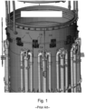
- Fig. 1 shows a perspective view of a shroud comprising a larger shroud cylinder 114 positioned above a smaller shroud cylinder 112.
- the shroud further includes a disc section (middle ring) connecting the larger shroud cylinder 114 to the smaller shroud cylinder 112 through two circumferential welding conventionally named H2 and H3 welds.
- Fig. 1 furthermore shows a plurality of blocks 110 that are bolted across the H2 and H3 welds to secure the smaller shroud cylinder 112 and the larger shroud cylinder 114 to each other.
- a securing device as defined in claim 1 is provided for installing on an outer circumferential surface of a nuclear reactor core shroud and in contact with an inner circumferential surface of a pressure vessel.
- a method as defined in claim 9 is provided for installing a securing device on an outer circumferential surface of a nuclear reactor core shroud and in contact with an inner circumferential surface of a pressure vessel.
- the present disclosure provides a securing device with lateral support to reduce the quantity of repairs needed to provide the securing device for safe operation.
- the securing device of the present disclosure utilizes underwater threading of a blind hole to allow the bases of the securing device to be bolted directed to the core shroud without making a through hole, reducing the bypass fluid flow inside the core shroud that is associated with repairs that go entirely through the wall of the shroud.
- Fig. 2 schematically shows a nuclear reactor core shroud assembly 10 that is surrounded by a nuclear reactor pressure vessel in a nuclear reactor.
- Shroud assembly 10 is centered on a vertically extending longitudinal center axis CA.
- the terms circumferential, radial, axial and derivatives thereof are defined with respect to center axis, unless otherwise specified.
- Shroud assembly 10 includes a shroud 12 that surrounds nuclear fuel assemblies and is surrounded by a plurality of jet pump assemblies 14 that are provided in an annular space, known as a downcomer annular, radially between shroud 12 and the pressure vessel.
- Each jet pump assembly 14 includes two jet pumps 16 that are coupled to a riser pipe 18 by a ram's head 20. Water enters riser pipe 18, passes through ram's head 20 and is then driven downward into an inlet mixer 22 by drive nozzles 24.
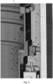
- FIGs. 3 and 4 show perspective views of a securing device 30 in accordance with an embodiment of the present invention installed on an outer circumferential surface 32 of shroud 12 above jet pump assemblies 14.
- Fig. 4 shows how securing device 30 is wedged radially between outer circumferential surface 32 of shroud 12 and an inner circumferential surface 34 of pressure vessel 36.
- shroud 12 includes a first cylindrical section 38 and a second cylindrical section 40 having an outer diameter that is less than first cylindrical section 38.
- First cylindrical section 38 is positioned above second cylindrical section 40.
- Shroud 12 further includes a disc section 42 connecting first cylindrical section 38 to second cylindrical section 40.
- Disc section 42 extends radially inward from first cylindrical section 38 to second cylindrical section 40.
- Sections 38, 40, 42 together define outer circumferential surface 32 of shroud 12, with section 38 defining a first outer circumferential surface section 32a, section 40 defining a second outer circumferential surface section 32b, and disc section 42 defining a third outer circumferential surface section 32c.
- Sections 38, 42 have the same outer diameter, which is greater than the outer diameter of section 40.
- Disc section 42 is fixed to first cylindrical section 38 by a first weld 44 - known as the H2 weld - and is fixed to second cylindrical section 40 by a second weld 46 - known as the H3 weld. Over time, welds 44, 46 have indications which require some type of repair to allow continued safe operation of shroud 12. Securing devices 30 are applied to shroud 12 to radially secure sections 38, 40, 42 with respect to each other to allowed continued operation of shroud 12.
- securing device 30 includes a stepped base 48 that is configured for contacting outer circumferential surface 32 of shroud 12.
- Base 48 includes a first radial contact section 50 having a contact surface 50a configured for radially contacting first outer circumferential surface section 32a and for radially contacting third outer circumferential surface section 32c.
- Base 48 also includes a second radial contact section 52, which is radially offset from first radial contact section 50, having a contact surface 52a configured for radially contacting second outer circumferential surface section 32b.
- Base 48 further includes an axial contact section 54, which connects radial contact sections 50, 52, having a contact surface 54a configured for axially contacting a lower radially extending surface 42a of disc section 42.
- Securing device 30 further includes a radial extender 56 configured for pressing against inner circumferential surface 34 of pressure vessel 36 to wedge securing device 30 radially between outer circumferential surface 32 of shroud 12 and inner circumferential surface 34 of pressure vessel 36.
- Radial extender 56 includes a first portion in the form of a stationary support portion 58 rigidly fixed to base 48 and a second portion in the form of a movable contact portion 60 that is radially movable with respect to base 48 by an actuator 62 of radial extender 56.
- stationary support portion 58 includes a sloped surface 64 ( Figs. 5a, 5b ) and movable contact portion 60 includes a sloped surface 66 ( Figs. 5a, 5b ).
- Portions 58, 60 are configured such that axial movement of movable contact portion 60 by actuator 62 moves movable contact portion 58 radially with respect to base 48 and stationary support portion 58.
- the axial movement of movable contact portion 60 varies a radial distance between contact surface 50a of base 48 and a contact surface 56a of radial extender 56.
- Base 48 includes a plurality of holes 50b, 52b passing radially therethrough. More specifically, first radial contact section 50 includes two holes 50b passing radially therethrough and second radial contact section 52 includes two holes 52b passing radially therethrough. Holes 50b pass from contact surface 50a to an outer surface 50c of first radial contact section 50 and holes 52b pass from contact surface 52a to an outer surface 52c of second radial contact section 50. Each of holes 50b, 52b receives a respective fastener 68, 70, which in a preferred embodiment are bolts, for mounting securing device 30 on shroud 12. Each of fasteners 68, 70 includes a respective threaded shank 68a, 70a ( Figs.
- first cylindrical section 38 includes two threaded holes 72 formed therein extending from outer circumferential surface section 32a into first cylindrical section 38, without breaching an inner circumferential surface 38a of section 38
- second cylindrical section 40 includes two threaded holes 74 formed therein extending from outer circumferential surface section 32b into second cylindrical section 40, without breaching an inner circumferential surface 40a of section 40.
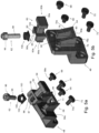
- Figs. 5a, 5b show exploded views of securing device 30.
- base 48 is formed integrally as a single piece with stationary support portion 58.
- Stationary support portion 58 protrudes radially from outer surface 50c of first radial contact section 50 and forms a first wedge part 51 including three walls 76, 78, 80 extending from outer surface 50c that define a receptacle 82 configured for receiving a first end 60a of movable contact portion 60.
- First and second walls 76, 78 define identical side walls of support portion 58 and third wall 80 defines a bottom wall.
- Third wall 80 includes a threaded axially extending hole 84 passing entirely therethrough axially and configured for receiving a portion of actuator 62.
- Walls 76, 78 each have a tapered irregular prism shape such that walls 76, 78 become progressively larger in the radial direction as walls 76, 78 extend downward toward bottom wall 80.
- Walls 76, 78, 80 together form sloped surface 64 of support portion 58.
- each of walls 76, 78 includes a respective sloped surface section 76a, 78a that extends further away from first radial contact section 50 as surface sections 76a, 78a extend downward.
- wall 80 also includes a sloped surface section 80a that is coincident and coextensive with surface sections 76a, 78a; however, in other embodiments surface section 80a may have a different shape.
- Movable contact portion 60 includes a first end 60a for moving axially and vertically within receptacle 82 and a second end 60b configured for contacting inner circumferential surface 34 of pressure vessel 36 via contact surface 56a.
- First end 60a includes an insertion section 86 that is axially slidable within receptacle 82 between side walls 76, 78 and toward and away from bottom wall 80.
- Insertion section 86 includes a radially elongated slot 87 passing axially therethrough that is configured for receiving actuator 62. Insertion section 86 is connected to a second wedge part 89 and laterally between side walls 88, 90 of second wedge part 89 that form sloped surface 66.
- Walls 88, 90 each include a sloped surface section 88a, 90a forming sloped surface 66. Walls 88, 90 are shaped such that sloped surface 66 has a complementary shape to sloped surface 64, causing sloped surface 64 to rest flush against sloped surface 66 while movable contact portion 60 is being moved axially and radially by actuator 62.
- Contact portion 60 further includes an arm 92 extending radially from wedge part 89 to a stop 94, which is provided on second end 60b, that includes contact surface 56a, which defines a radial outermost surface of securing device 30.
- Actuator 62 is formed as a bolt including a head 96 and a threaded shank 98. Actuator 62 is centered on insertion section 86 between walls 88, 90 by a washer 100. Washer 100 includes a square base 102 configured for sliding in contact with lateral surfaces of walls 88, 90 as actuator 62 is moved between radial ends of elongated slot 87. Actuator 62 is axially movable in elongated slot 87 due to a radial length of slot 87 being greater than a diameter of shank 98. Base 102 contacts a radially inner surface of an outer wall 104 of wedge part 89 when actuator 62 is at a radially outermost position of actuator 62.
- Washer 100 extends laterally between side walls 88, 90. During the axial movement of actuator 62, base 102 moves radially along walls 88, 90 and toward or away from outer wall 104. Washer 100 further includes a cylindrical centering wall 106 extending axially upward from base 102 that is configured for receiving head 96 to align actuator 62.
- Fig. 6 shows a top plan view of securing device 30 with portions 58, 60 connected together by actuator 62.
- actuator 62 is at a radially innermost position of actuator 62, such that a radially innermost contact surface 86a of insertion section 86 contacts outer surface 50c of first radial contact section 50.
- wedge part 89 radially overlaps wedge part 51.
- Figs. 7a to 7d illustrate how the actuator 62 is moved axially within hole 84 and radially in elongated slot 87 to vary the radial extent of securing device 30.
- Figs. 7a and 7b illustrate actuator 62 in a first position in which securing device 30 is in a radially contracted position, with Fig. 7a showing a side view of securing device 30 and Fig. 7b showing a cross-sectional side view of securing device 30. In the position shown in Figs.
- second wedge part 89 is positioned at a top of wedge part 51 and actuator 62 is positioned such that a bottom of shank 98 is in hole 84 and a top of shank 98 is positioned in elongated hole 87 spaced away from both a radially inner edge 87a and a radially outer edge 87b of elongated hole 87.
- Figs. 7c and 7d illustrate actuator 62 in a second position in which securing device 30 is in a radially extended position, with Fig. 7c showing a side view of securing device 30 and Fig. 7d showing a cross-sectional side view of securing device 30.
- second wedge part 89 is positioned near a bottom of wedge part 51 and actuator 62 is positioned such that a bottom of shank 98 is below hole 84 and a top of shank 98 is positioned in elongated hole 87 in contact with radially inner edge 87a.
- actuator 62 is rotated such that shank 98 moves axially downward in hole 84 via the engagement of the helical threads of shank 98 and the helical threads of hole 84.
- sloped surface 66 of movable contact portion 60 slides along sloped surface 64 of stationary support portion 58, causing movable contact portion 60 to move radially outward away from base 48.
- movable contact portion 60 radially outward away from base 48 allows contact surface 56a of stop 94 to press against inner circumferential surface 34 of pressure vessel 36, forcing contact surface 50a of first radial contact section 50 radially against first outer circumferential surface section 32a of shroud 12 and forcing contact surface 52a of second radial contact section 52 radially against second outer circumferential surface section 32b of shroud 12.
- a method of installing securing device 30 on shroud 12 first includes machining threaded holes 72, 74 in shroud 12. Then, the method includes aligning holes 50b, 52b of base 48 with the respective holes 72, 74 in shroud and installing fasteners 68, 70 through the respective holes 50b, 52b and into the respective holes 72, 74 such that base 48 is fixed to shroud 12. Next, actuator 62 is actuated axially downward such that sloped surface 66 of movable contact portion 60 moves along sloped surface 64 of stationary support portion 58 and movable contact portion 60 is forced radially outward against inner circumferential surface 34 of pressure vessel 36. A plurality of securing devices 30 are circumferentially spaced from each other on shroud 12 to support the alignment of sections 38, 40, 42 of shroud 12 with respect to each other and with respect to the vessel 36.
- a thermal expansion of shroud 12 and pressure vessel 36 may be compensated with a series of Belleville washers that can either be below movable contact portion 60 or above movable contact portion 60 on actuator 62.
- the location of the washers can be determined as the thermal analysis is completed to see the differential growth characteristics.
Landscapes
- Physics & Mathematics (AREA)
- Engineering & Computer Science (AREA)
- Plasma & Fusion (AREA)
- General Engineering & Computer Science (AREA)
- High Energy & Nuclear Physics (AREA)
- Monitoring And Testing Of Nuclear Reactors (AREA)
- Pressure Vessels And Lids Thereof (AREA)
Description
- The present disclosure relates generally to nuclear reactors and more specifically to devices for securing core shrouds in nuclear reactors.
- Boiling water reactors have a core shroud that holds the fuel in proper alignment with the control rod drives so that the plant can shut down safely. The core shroud has circumferential welds that hold cylinders of the shroud together to maintain alignment. Some of these circumferential welds have indications which require some type of repair to allow continued safe operation.
-
U.S. Patent No.: 5,402,570 discloses a method for repairing boiling water reactor shrouds using a plurality of tie rods that apply vertical compressive forces to the shrouds.U.S. Patent No.: 5,809,100 discloses a method and tool for measuring a preload on tie rods applying forces to nuclear reactor core shrouds.U.S. Patent No.: 3,850,795 discloses screw jacks for clamping a nuclear reactor core shroud to a pressure vessel.
U.S. Patent No.: 6,343,107 discloses a stabilizer assembly comprising two wedges arranged between a nuclear reactor core shroud and a pressure vessel, the two wedges being adjusted with a tightening bolt. -
Fig. 1 shows a perspective view of a shroud comprising alarger shroud cylinder 114 positioned above a smaller shroud cylinder 112. The shroud further includes a disc section (middle ring) connecting thelarger shroud cylinder 114 to the smaller shroud cylinder 112 through two circumferential welding conventionally named H2 and H3 welds.Fig. 1 furthermore shows a plurality ofblocks 110 that are bolted across the H2 and H3 welds to secure the smaller shroud cylinder 112 and thelarger shroud cylinder 114 to each other. These repairs include (i) a multitude - e.g., approximately twelve, of these blocks (ii) with bolts 116fixing blocks 110 tocylinders 112, 114 passing entirely throughcylinders 112, 114 . Both features (i) and (ii) are needed to achieve the axially and radially support for the shroud cylinders in operation. - A securing device as defined in
claim 1 is provided for installing on an outer circumferential surface of a nuclear reactor core shroud and in contact with an inner circumferential surface of a pressure vessel. - A method as defined in claim 9 is provided for installing a securing device on an outer circumferential surface of a nuclear reactor core shroud and in contact with an inner circumferential surface of a pressure vessel.
- The present invention is described below by reference to the following drawings, in which:
-
Fig. 1 shows a perspective view of a conventional arrangement for securing sections of a nuclear reactor core shroud with respect to each other; -
Fig. 2 shows a nuclear reactor core shroud assembly; -
Figs. 3 and4 show perspective views of a securing device in accordance with an embodiment of the present invention installed on an outer circumferential surface of a shroud; -
Figs. 5a, 5b show exploded views of the securing device shown inFigs. 3 and4 ; -
Fig. 6 shows a top plan view of a securing device with stationary and movable portions connected together by an actuator; and -
Figs. 7a to 7d illustrate how the actuator is moved axially to vary the radial extent of the securing device. - One problem with conventional techniques is that they are very expensive to implement, due to excessive time required for installation and the expense of the hardware to be fabricated for the repair. Another problem with the conventional technique represented in
Fig. 1 is that the through holes in the shroud cylinders impact the tightness of the shroud and the bolts emerging inside the shroud cylinders impact the fluid flow inside of shroud cylinders. - The present disclosure provides a securing device with lateral support to reduce the quantity of repairs needed to provide the securing device for safe operation. The securing device of the present disclosure utilizes underwater threading of a blind hole to allow the bases of the securing device to be bolted directed to the core shroud without making a through hole, reducing the bypass fluid flow inside the core shroud that is associated with repairs that go entirely through the wall of the shroud.
- Advantages of the securing device of the present disclosure may be as follows:
- providing axial and radial support for welds on the core shroud with a minimal number of securing devices installed (potentially only four securing devices of the present disclosure circumferentially spaced at 90 degree increments, compared with approximately twelve as shown in
Fig. 1 ); - attaching the securing devices of the present disclosure to the shroud does not increase bypass fluid flow within the shroud; and
- the tapered wedge design of the securing devices of the present disclosure allows the lateral support of the securing device to be adjusted during installation for optimal fit with respect to the pressure vessel, allowing for thermal expansion during operation (belleville washers may be utilized to allow compliance on the lateral supports).
-
Fig. 2 schematically shows a nuclear reactorcore shroud assembly 10 that is surrounded by a nuclear reactor pressure vessel in a nuclear reactor.Shroud assembly 10 is centered on a vertically extending longitudinal center axis CA. As used herein, the terms circumferential, radial, axial and derivatives thereof are defined with respect to center axis, unless otherwise specified. Shroudassembly 10 includes ashroud 12 that surrounds nuclear fuel assemblies and is surrounded by a plurality ofjet pump assemblies 14 that are provided in an annular space, known as a downcomer annular, radially betweenshroud 12 and the pressure vessel. Eachjet pump assembly 14 includes twojet pumps 16 that are coupled to a riser pipe 18 by a ram's head 20. Water enters riser pipe 18, passes through ram's head 20 and is then driven downward into an inlet mixer 22 by drive nozzles 24. -
Figs. 3 and4 show perspective views of asecuring device 30 in accordance with an embodiment of the present invention installed on an outercircumferential surface 32 ofshroud 12 abovejet pump assemblies 14.Fig. 4 shows how securingdevice 30 is wedged radially between outercircumferential surface 32 ofshroud 12 and an inner circumferential surface 34 ofpressure vessel 36. - As shown in
Fig. 3 and4 ,shroud 12 includes a firstcylindrical section 38 and a secondcylindrical section 40 having an outer diameter that is less than firstcylindrical section 38. Firstcylindrical section 38 is positioned above secondcylindrical section 40. Shroud 12 further includes adisc section 42 connecting firstcylindrical section 38 to secondcylindrical section 40.Disc section 42 extends radially inward from firstcylindrical section 38 to secondcylindrical section 40.Sections circumferential surface 32 ofshroud 12, withsection 38 defining a first outer circumferential surface section 32a,section 40 defining a second outer circumferential surface section 32b, anddisc section 42 defining a third outer circumferential surface section 32c.Sections section 40. -
Disc section 42 is fixed to firstcylindrical section 38 by a first weld 44 - known as the H2 weld - and is fixed to secondcylindrical section 40 by a second weld 46 - known as the H3 weld. Over time, welds 44, 46 have indications which require some type of repair to allow continued safe operation ofshroud 12. Securingdevices 30 are applied toshroud 12 to radially securesections shroud 12. - As shown in
Figs. 3 and4 , securingdevice 30 includes astepped base 48 that is configured for contacting outercircumferential surface 32 ofshroud 12.Base 48 includes a firstradial contact section 50 having a contact surface 50a configured for radially contacting first outer circumferential surface section 32a and for radially contacting third outer circumferential surface section 32c.Base 48 also includes a second radial contact section 52, which is radially offset from firstradial contact section 50, having a contact surface 52a configured for radially contacting second outer circumferential surface section 32b.Base 48 further includes an axial contact section 54, which connectsradial contact sections 50, 52, having a contact surface 54a configured for axially contacting a lower radially extending surface 42a ofdisc section 42. - Securing
device 30 further includes aradial extender 56 configured for pressing against inner circumferential surface 34 ofpressure vessel 36 towedge securing device 30 radially between outercircumferential surface 32 ofshroud 12 and inner circumferential surface 34 ofpressure vessel 36.Radial extender 56 includes a first portion in the form of astationary support portion 58 rigidly fixed tobase 48 and a second portion in the form of amovable contact portion 60 that is radially movable with respect tobase 48 by anactuator 62 ofradial extender 56. As described further below,stationary support portion 58 includes a sloped surface 64 (Figs. 5a, 5b ) andmovable contact portion 60 includes a sloped surface 66 (Figs. 5a, 5b ).Portions movable contact portion 60 byactuator 62 movesmovable contact portion 58 radially with respect tobase 48 andstationary support portion 58. The axial movement ofmovable contact portion 60 varies a radial distance between contact surface 50a ofbase 48 and acontact surface 56a ofradial extender 56. -
Base 48 includes a plurality of holes 50b, 52b passing radially therethrough. More specifically, firstradial contact section 50 includes two holes 50b passing radially therethrough and second radial contact section 52 includes two holes 52b passing radially therethrough. Holes 50b pass from contact surface 50a to anouter surface 50c of firstradial contact section 50 and holes 52b pass from contact surface 52a to an outer surface 52c of secondradial contact section 50. Each of holes 50b, 52b receives arespective fastener device 30 onshroud 12. Each offasteners shank Figs. 5a, 5b ) that extends through the respective hole 50b, 52b into a respective one of a plurality of threaded blind holes 72, 74 formed inshroud 12 such that the threads ofshanks 68a, 68b and holes 72, 74 intermesh to fix securingdevice 30 toshroud 12. In particular, firstcylindrical section 38 includes two threaded holes 72 formed therein extending from outer circumferential surface section 32a into firstcylindrical section 38, without breaching an inner circumferential surface 38a ofsection 38, and secondcylindrical section 40 includes two threaded holes 74 formed therein extending from outer circumferential surface section 32b into secondcylindrical section 40, without breaching an inner circumferential surface 40a ofsection 40. -
Figs. 5a, 5b show exploded views of securingdevice 30. As shown inFigs. 5a, 5b ,base 48 is formed integrally as a single piece withstationary support portion 58.Stationary support portion 58 protrudes radially fromouter surface 50c of firstradial contact section 50 and forms afirst wedge part 51 including threewalls outer surface 50c that define areceptacle 82 configured for receiving afirst end 60a ofmovable contact portion 60. First andsecond walls support portion 58 andthird wall 80 defines a bottom wall.Third wall 80 includes a threaded axially extendinghole 84 passing entirely therethrough axially and configured for receiving a portion ofactuator 62.Walls walls walls bottom wall 80.Walls surface 64 ofsupport portion 58. In particular, each ofwalls surface section radial contact section 50 assurface sections Figs. 5a, 5b ,wall 80 also includes a slopedsurface section 80a that is coincident and coextensive withsurface sections section 80a may have a different shape. -
Movable contact portion 60 includes afirst end 60a for moving axially and vertically withinreceptacle 82 and asecond end 60b configured for contacting inner circumferential surface 34 ofpressure vessel 36 viacontact surface 56a.First end 60a includes aninsertion section 86 that is axially slidable withinreceptacle 82 betweenside walls bottom wall 80.Insertion section 86 includes a radiallyelongated slot 87 passing axially therethrough that is configured for receivingactuator 62.Insertion section 86 is connected to asecond wedge part 89 and laterally betweenside walls second wedge part 89 that form slopedsurface 66.Walls sloped surface section surface 66.Walls surface 66 has a complementary shape to slopedsurface 64, causing slopedsurface 64 to rest flush against slopedsurface 66 whilemovable contact portion 60 is being moved axially and radially byactuator 62.Contact portion 60 further includes anarm 92 extending radially fromwedge part 89 to astop 94, which is provided onsecond end 60b, that includescontact surface 56a, which defines a radial outermost surface of securingdevice 30. -
Actuator 62 is formed as a bolt including ahead 96 and a threadedshank 98.Actuator 62 is centered oninsertion section 86 betweenwalls washer 100.Washer 100 includes asquare base 102 configured for sliding in contact with lateral surfaces ofwalls actuator 62 is moved between radial ends ofelongated slot 87.Actuator 62 is axially movable inelongated slot 87 due to a radial length ofslot 87 being greater than a diameter ofshank 98.Base 102 contacts a radially inner surface of anouter wall 104 ofwedge part 89 whenactuator 62 is at a radially outermost position ofactuator 62.Outer wall 104 extends laterally betweenside walls actuator 62,base 102 moves radially alongwalls outer wall 104.Washer 100 further includes a cylindrical centeringwall 106 extending axially upward frombase 102 that is configured for receivinghead 96 to alignactuator 62. -
Fig. 6 shows a top plan view of securingdevice 30 withportions actuator 62. In the view inFig. 6 ,actuator 62 is at a radially innermost position ofactuator 62, such that a radially innermost contact surface 86a ofinsertion section 86 contactsouter surface 50c of firstradial contact section 50. As shown in the view inFig. 6 ,wedge part 89 radially overlapswedge part 51. -
Figs. 7a to 7d illustrate how theactuator 62 is moved axially withinhole 84 and radially inelongated slot 87 to vary the radial extent of securingdevice 30.Figs. 7a and 7b illustrateactuator 62 in a first position in which securingdevice 30 is in a radially contracted position, withFig. 7a showing a side view of securingdevice 30 andFig. 7b showing a cross-sectional side view of securingdevice 30. In the position shown inFigs. 7a, 7b ,second wedge part 89 is positioned at a top ofwedge part 51 andactuator 62 is positioned such that a bottom ofshank 98 is inhole 84 and a top ofshank 98 is positioned inelongated hole 87 spaced away from both a radiallyinner edge 87a and a radiallyouter edge 87b ofelongated hole 87. -
Figs. 7c and 7d illustrateactuator 62 in a second position in which securingdevice 30 is in a radially extended position, withFig. 7c showing a side view of securingdevice 30 andFig. 7d showing a cross-sectional side view of securingdevice 30. In the position shown inFigs. 7c, 7d ,second wedge part 89 is positioned near a bottom ofwedge part 51 andactuator 62 is positioned such that a bottom ofshank 98 is belowhole 84 and a top ofshank 98 is positioned inelongated hole 87 in contact with radiallyinner edge 87a. - In order to move from the position in
Figs. 7a, 7b , where securingdevice 30 has a minimum radial length L1, to the position inFigs. 7c, 7d , where securingdevice 30 has a maximum radial length L2,actuator 62 is rotated such thatshank 98 moves axially downward inhole 84 via the engagement of the helical threads ofshank 98 and the helical threads ofhole 84. Asactuator 62 is moved axially downward, slopedsurface 66 ofmovable contact portion 60 slides along slopedsurface 64 ofstationary support portion 58, causingmovable contact portion 60 to move radially outward away frombase 48. The movement ofmovable contact portion 60 radially outward away frombase 48 allowscontact surface 56a ofstop 94 to press against inner circumferential surface 34 ofpressure vessel 36, forcing contact surface 50a of firstradial contact section 50 radially against first outer circumferential surface section 32a ofshroud 12 and forcing contact surface 52a of second radial contact section 52 radially against second outer circumferential surface section 32b ofshroud 12. - A method of installing securing
device 30 onshroud 12 first includes machining threaded holes 72, 74 inshroud 12. Then, the method includes aligning holes 50b, 52b ofbase 48 with the respective holes 72, 74 in shroud and installingfasteners base 48 is fixed toshroud 12. Next,actuator 62 is actuated axially downward such that slopedsurface 66 ofmovable contact portion 60 moves along slopedsurface 64 ofstationary support portion 58 andmovable contact portion 60 is forced radially outward against inner circumferential surface 34 ofpressure vessel 36. A plurality of securingdevices 30 are circumferentially spaced from each other onshroud 12 to support the alignment ofsections shroud 12 with respect to each other and with respect to thevessel 36. - A thermal expansion of
shroud 12 andpressure vessel 36 may be compensated with a series of Belleville washers that can either be belowmovable contact portion 60 or abovemovable contact portion 60 onactuator 62. The location of the washers can be determined as the thermal analysis is completed to see the differential growth characteristics. - In the preceding specification, the invention has been described with reference to specific exemplary embodiments and examples thereof. It will, however, be evident that various modifications and changes may be made thereto without departing from the invention. The specification and drawings are accordingly to be regarded in an illustrative manner rather than a restrictive sense. In particular, in BWR reactors shroud, any linking two shroud cylinders assembled through disc section and welding lines can be secured by using the security device and the method of the present invention.
Claims (12)
- A securing device for installation on an outer circumferential surface of a nuclear reactor core shroud and in contact with an inner circumferential surface of a nuclear reactor pressure vessel, the securing device comprising:a base (48) configured for contacting the outer circumferential surface of the nuclear reactor core shroud; anda radial extender (56) including an actuator (62), a stationary support section (58) fixed to the base (48) and a movable contact section (60), the radial extender (56) being configured such that the movable contact section (60) is movable along the stationary support section (58) by the actuator (62) to force the movable contact section (60) radially into the inner circumferential surface of the pressure vesselwherein the radial extender (56) is configured such that an axial movement of the actuator (62) moves the movable contact section (60) radially,wherein the movable contact section (60) includes an elongated hole (87) formed therein, the actuator (62) being radially movable in the elongated hole (87) as the actuator (62) moves the movable contact section (60) radially.
- The securing device as recited in claim 1 further comprising a plurality of fasteners for passing through the base (48) into the nuclear reactor core shroud.
- The securing device as recited in claim 1 or 2 wherein the stationary support section (58) includes an axially extending hole (84) formed therein, the actuator (62) being movable in the axially extending hole (84) to move the movable contact section (60) radially.
- The securing device as recited in any one of the preceding claims wherein the stationary support section (58) includes a first wedge part (51) and the movable contact section (60) includes a second wedge part (89), the first wedge part (51) being slidable along the second wedge (89) part by the actuator (62) to force the movable contact section (60) radially into the inner circumferential surface of the pressure vessel.
- The securing device as recited in claim 4 wherein the first wedge part (51) includes a first sloped surface (64) and the second wedge (89) part includes a second sloped surface (66) that is complementary to the first sloped surface (64).
- The securing device as recited in any one of the preceding claims wherein the actuator (62) is a bolt extending through the movable contact section (60) and through the stationary support section (58).
- The securing device as recited in any one of the preceding claims wherein the base (48) includes a first radial contact section (50) having a contact surface configured for radially contacting a first outer circumferential surface section of the nuclear reactor core shroud and a second radial contact section (52) having a contact surface configured for radially contacting a second outer circumferential surface section of the nuclear reactor core shroud, the first radial contact section (50) being radially offset from the second radial contact section (52).
- The securing device as recited in any one of the preceding claims wherein the stationary support section (58) and the movable contact section (60) are connected together by the actuator (62).
- A method for installing a securing device on an outer circumferential surface of a nuclear reactor core shroud and in contact with an inner circumferential surface of a pressure vessel, the method comprising:fixing a base (48) of the securing device to outer circumferential surface of the nuclear reactor core shroud; andmoving an actuator (62) of the securing device to force a movable contact section (60) of the securing device along a stationary support section (58) of the securing device to force the movable contact section (60) radially into the inner circumferential surface of the pressure vessel,wherein the movable contact section (60) includes an elongated hole (87) therein, the moving of the actuator (62) including moving the actuator (62) radially within the elongated hole (87).
- The method as recited in claim 9 wherein the fixing of the base (48) to the outer circumferential surface of the nuclear reactor core shroud includes machining blind holes into the shroud and installing fasteners through the base and into the blind holes.
- The method as recited in claim 9 or claim 10 wherein the stationary support section (58) includes a first wedge part (50) and the movable contact section includes a second wedge part (52), the moving of the actuator (62) including sliding the second wedge part (52) along the first wedge part (50) via the actuator (62).
- The method as recited in any one of claims 9 to 11 wherein the stationary support section (58) includes an axially extending hole (84), the moving of the actuator (62) including moving the actuator (62) axially within the axially extending hole (84).
Applications Claiming Priority (2)
| Application Number | Priority Date | Filing Date | Title |
|---|---|---|---|
| US16/414,233 US11289216B2 (en) | 2019-05-16 | 2019-05-16 | Nuclear reactor core shroud securing device |
| PCT/US2020/032998 WO2020232310A1 (en) | 2019-05-16 | 2020-05-14 | Nuclear reactor core shroud securing device |
Publications (2)
| Publication Number | Publication Date |
|---|---|
| EP3970164A1 EP3970164A1 (en) | 2022-03-23 |
| EP3970164B1 true EP3970164B1 (en) | 2024-06-19 |
Family
ID=72046989
Family Applications (1)
| Application Number | Title | Priority Date | Filing Date |
|---|---|---|---|
| EP20754410.7A Active EP3970164B1 (en) | 2019-05-16 | 2020-05-14 | Nuclear reactor core shroud securing device |
Country Status (7)
| Country | Link |
|---|---|
| US (1) | US11289216B2 (en) |
| EP (1) | EP3970164B1 (en) |
| JP (2) | JP7638228B2 (en) |
| ES (1) | ES2984876T3 (en) |
| MX (1) | MX2021013746A (en) |
| TW (1) | TWI846874B (en) |
| WO (1) | WO2020232310A1 (en) |
Families Citing this family (1)
| Publication number | Priority date | Publication date | Assignee | Title |
|---|---|---|---|---|
| CN117242530A (en) | 2021-04-19 | 2023-12-15 | 霍尔泰克国际公司 | Self-adjusting anti-seismic system for nuclear fuel storage |
Citations (3)
| Publication number | Priority date | Publication date | Assignee | Title |
|---|---|---|---|---|
| US3791151A (en) * | 1972-11-08 | 1974-02-12 | D Plank | Shoring apparatus |
| US3850795A (en) * | 1972-05-01 | 1974-11-26 | Babcock Atlantique Sa | Means for adjustable clamping skirt between pressure vessel and core |
| US6343107B1 (en) * | 2000-02-01 | 2002-01-29 | General Electric Company | Shroud repair apparatus |
Family Cites Families (14)
| Publication number | Priority date | Publication date | Assignee | Title |
|---|---|---|---|---|
| GB827085A (en) * | 1956-06-29 | 1960-02-03 | Atomic Energy Commission | Nuclear reactors |
| US5402570A (en) | 1994-02-02 | 1995-04-04 | Mpr Associates, Inc. | Method for repairing boiling water reactor shrouds |
| JPH07270570A (en) * | 1994-03-31 | 1995-10-20 | Hitachi Ltd | Reactor core support structure with seismic support |
| US5621778A (en) * | 1994-05-19 | 1997-04-15 | General Electric Company | Shroud restraint stabilizer |
| TW363193B (en) * | 1994-12-15 | 1999-07-01 | Mpr Associates Inc | Method and apparatus for repairing boiling water reactor shrouds |
| US5623525A (en) * | 1995-09-22 | 1997-04-22 | General Electric Company | Tool for lifting tie rod during shroud repair |
| US5646969A (en) * | 1995-09-22 | 1997-07-08 | General Electric Company | Apparatus for installing tie rod assembly in space between jet pump assemblies with limited vertical access |
| US5589640A (en) | 1996-04-03 | 1996-12-31 | Butler; Patrick J. | Method for detecting changes in preload on a tie rod installed as part of a core shroud repair in a boiling water reactor |
| JPH11125685A (en) | 1997-10-22 | 1999-05-11 | Babcock Hitachi Kk | Support device of reactor pressure vessel |
| CA2535280C (en) * | 2003-08-15 | 2013-02-19 | Pebble Bed Modular Reactor (Proprietary) Limited | A support arrangement |
| EP1796876B1 (en) * | 2004-09-28 | 2011-08-24 | Ateliers LR Etanco | Device for the semi-automatic screwing of fixing elements |
| US9269463B2 (en) * | 2012-03-14 | 2016-02-23 | Ihi Southwest Technologies, Inc. | Method and apparatus of inspecting the upper core shroud of a nuclear reactor vessel |
| US9638227B2 (en) * | 2014-02-20 | 2017-05-02 | GE-Hitachi Nuclear Energry Americas LLC | Apparatuses and methods for structurally replacing cracked welds in nuclear power plants |
| JP6785192B2 (en) | 2017-06-13 | 2020-11-18 | 日立Geニュークリア・エナジー株式会社 | Reactor pressure vessel pedestal support structure and nuclear plant |
-
2019
- 2019-05-16 US US16/414,233 patent/US11289216B2/en active Active
-
2020
- 2020-05-14 MX MX2021013746A patent/MX2021013746A/en unknown
- 2020-05-14 JP JP2021568609A patent/JP7638228B2/en active Active
- 2020-05-14 EP EP20754410.7A patent/EP3970164B1/en active Active
- 2020-05-14 WO PCT/US2020/032998 patent/WO2020232310A1/en not_active Ceased
- 2020-05-14 ES ES20754410T patent/ES2984876T3/en active Active
- 2020-05-15 TW TW109116227A patent/TWI846874B/en active
-
2024
- 2024-10-16 JP JP2024180768A patent/JP2025011266A/en active Pending
Patent Citations (3)
| Publication number | Priority date | Publication date | Assignee | Title |
|---|---|---|---|---|
| US3850795A (en) * | 1972-05-01 | 1974-11-26 | Babcock Atlantique Sa | Means for adjustable clamping skirt between pressure vessel and core |
| US3791151A (en) * | 1972-11-08 | 1974-02-12 | D Plank | Shoring apparatus |
| US6343107B1 (en) * | 2000-02-01 | 2002-01-29 | General Electric Company | Shroud repair apparatus |
Also Published As
| Publication number | Publication date |
|---|---|
| WO2020232310A1 (en) | 2020-11-19 |
| ES2984876T3 (en) | 2024-10-31 |
| JP2022533172A (en) | 2022-07-21 |
| TWI846874B (en) | 2024-07-01 |
| JP2025011266A (en) | 2025-01-23 |
| EP3970164A1 (en) | 2022-03-23 |
| US20200365286A1 (en) | 2020-11-19 |
| US11289216B2 (en) | 2022-03-29 |
| TW202121436A (en) | 2021-06-01 |
| MX2021013746A (en) | 2022-02-11 |
| JP7638228B2 (en) | 2025-03-03 |
Similar Documents
| Publication | Publication Date | Title |
|---|---|---|
| US5521951A (en) | Reactor core shroud repair with tapered pins | |
| EP0944095B1 (en) | Apparatus for performing jet pump riser repairs | |
| US11721444B2 (en) | Method for installing extension tube in a nuclear reactor | |
| US5839192A (en) | Method and apparatus for repairing cracked core spray supply piping in a boiling water reactor | |
| US20190061121A1 (en) | Lower end fitting locknut for nuclear fuel assembly | |
| US5683216A (en) | Spring latching mechanisms for preventing relative movement of assembled components | |
| JP5032404B2 (en) | Fixing device for measuring pipe in reactor and fixing method using the same | |
| JPS6280309A (en) | Lock apparatus | |
| US5752807A (en) | Jet pump sensing line repair | |
| US4770846A (en) | Replacement support pin for guide tubes in operating plants | |
| US5600689A (en) | Method and apparatus for repairing boiling water reactor shrouds utilizing tie-rods with multiple longitudinal members | |
| US5781603A (en) | Method and apparatus for repair of nuclear reactor shroud | |
| US20040037615A1 (en) | Method and apparatus for repairing a riser brace in nuclear reactor | |
| US6240156B1 (en) | Top guide grid attachment for a boiling water reactor | |
| US5297176A (en) | Remotely replaceable fuel assembly alignment pin | |
| US11289216B2 (en) | Nuclear reactor core shroud securing device | |
| US6343107B1 (en) | Shroud repair apparatus | |
| JPH0421160B2 (en) | ||
| US4751039A (en) | Method of installing a sleeve within an instrumentation tube of a nuclear fuel assembly | |
| US4928291A (en) | Control cluster provided with removable control elements for a nuclear fuel reactor | |
| US6091791A (en) | Shroud attachment for a boiling water reactor | |
| US5084228A (en) | Sealing device for an instrumentation column penetrating the head of a pressurized-water nuclear reactor vessel | |
| US5600687A (en) | Steam dam slide with cable manipulator for radially positioning hoisted load in annulus | |
| KR20210038033A (en) | Jig apparatus for assembling and disassembling valve seat | |
| KR102187625B1 (en) | Method for replacing a rail for guiding a piece of equipment inside a nuclear reactor |
Legal Events
| Date | Code | Title | Description |
|---|---|---|---|
| STAA | Information on the status of an ep patent application or granted ep patent |
Free format text: STATUS: UNKNOWN |
|
| STAA | Information on the status of an ep patent application or granted ep patent |
Free format text: STATUS: THE INTERNATIONAL PUBLICATION HAS BEEN MADE |
|
| PUAI | Public reference made under article 153(3) epc to a published international application that has entered the european phase |
Free format text: ORIGINAL CODE: 0009012 |
|
| STAA | Information on the status of an ep patent application or granted ep patent |
Free format text: STATUS: REQUEST FOR EXAMINATION WAS MADE |
|
| 17P | Request for examination filed |
Effective date: 20211115 |
|
| AK | Designated contracting states |
Kind code of ref document: A1 Designated state(s): AL AT BE BG CH CY CZ DE DK EE ES FI FR GB GR HR HU IE IS IT LI LT LU LV MC MK MT NL NO PL PT RO RS SE SI SK SM TR |
|
| DAV | Request for validation of the european patent (deleted) | ||
| DAX | Request for extension of the european patent (deleted) | ||
| STAA | Information on the status of an ep patent application or granted ep patent |
Free format text: STATUS: EXAMINATION IS IN PROGRESS |
|
| 17Q | First examination report despatched |
Effective date: 20230221 |
|
| P01 | Opt-out of the competence of the unified patent court (upc) registered |
Effective date: 20230606 |
|
| GRAP | Despatch of communication of intention to grant a patent |
Free format text: ORIGINAL CODE: EPIDOSNIGR1 |
|
| STAA | Information on the status of an ep patent application or granted ep patent |
Free format text: STATUS: GRANT OF PATENT IS INTENDED |
|
| INTG | Intention to grant announced |
Effective date: 20240131 |
|
| GRAS | Grant fee paid |
Free format text: ORIGINAL CODE: EPIDOSNIGR3 |
|
| GRAA | (expected) grant |
Free format text: ORIGINAL CODE: 0009210 |
|
| STAA | Information on the status of an ep patent application or granted ep patent |
Free format text: STATUS: THE PATENT HAS BEEN GRANTED |
|
| AK | Designated contracting states |
Kind code of ref document: B1 Designated state(s): AL AT BE BG CH CY CZ DE DK EE ES FI FR GB GR HR HU IE IS IT LI LT LU LV MC MK MT NL NO PL PT RO RS SE SI SK SM TR |
|
| REG | Reference to a national code |
Ref country code: GB Ref legal event code: FG4D |
|
| REG | Reference to a national code |
Ref country code: CH Ref legal event code: EP |
|
| REG | Reference to a national code |
Ref country code: DE Ref legal event code: R096 Ref document number: 602020032652 Country of ref document: DE |
|
| REG | Reference to a national code |
Ref country code: SE Ref legal event code: TRGR |
|
| PG25 | Lapsed in a contracting state [announced via postgrant information from national office to epo] |
Ref country code: BG Free format text: LAPSE BECAUSE OF FAILURE TO SUBMIT A TRANSLATION OF THE DESCRIPTION OR TO PAY THE FEE WITHIN THE PRESCRIBED TIME-LIMIT Effective date: 20240619 |
|
| PG25 | Lapsed in a contracting state [announced via postgrant information from national office to epo] |
Ref country code: FI Free format text: LAPSE BECAUSE OF FAILURE TO SUBMIT A TRANSLATION OF THE DESCRIPTION OR TO PAY THE FEE WITHIN THE PRESCRIBED TIME-LIMIT Effective date: 20240619 Ref country code: HR Free format text: LAPSE BECAUSE OF FAILURE TO SUBMIT A TRANSLATION OF THE DESCRIPTION OR TO PAY THE FEE WITHIN THE PRESCRIBED TIME-LIMIT Effective date: 20240619 |
|
| REG | Reference to a national code |
Ref country code: LT Ref legal event code: MG9D |
|
| PG25 | Lapsed in a contracting state [announced via postgrant information from national office to epo] |
Ref country code: GR Free format text: LAPSE BECAUSE OF FAILURE TO SUBMIT A TRANSLATION OF THE DESCRIPTION OR TO PAY THE FEE WITHIN THE PRESCRIBED TIME-LIMIT Effective date: 20240920 |
|
| REG | Reference to a national code |
Ref country code: NL Ref legal event code: MP Effective date: 20240619 |
|
| PG25 | Lapsed in a contracting state [announced via postgrant information from national office to epo] |
Ref country code: LV Free format text: LAPSE BECAUSE OF FAILURE TO SUBMIT A TRANSLATION OF THE DESCRIPTION OR TO PAY THE FEE WITHIN THE PRESCRIBED TIME-LIMIT Effective date: 20240619 |
|
| PG25 | Lapsed in a contracting state [announced via postgrant information from national office to epo] |
Ref country code: NO Free format text: LAPSE BECAUSE OF FAILURE TO SUBMIT A TRANSLATION OF THE DESCRIPTION OR TO PAY THE FEE WITHIN THE PRESCRIBED TIME-LIMIT Effective date: 20240919 Ref country code: LV Free format text: LAPSE BECAUSE OF FAILURE TO SUBMIT A TRANSLATION OF THE DESCRIPTION OR TO PAY THE FEE WITHIN THE PRESCRIBED TIME-LIMIT Effective date: 20240619 Ref country code: HR Free format text: LAPSE BECAUSE OF FAILURE TO SUBMIT A TRANSLATION OF THE DESCRIPTION OR TO PAY THE FEE WITHIN THE PRESCRIBED TIME-LIMIT Effective date: 20240619 Ref country code: GR Free format text: LAPSE BECAUSE OF FAILURE TO SUBMIT A TRANSLATION OF THE DESCRIPTION OR TO PAY THE FEE WITHIN THE PRESCRIBED TIME-LIMIT Effective date: 20240920 Ref country code: FI Free format text: LAPSE BECAUSE OF FAILURE TO SUBMIT A TRANSLATION OF THE DESCRIPTION OR TO PAY THE FEE WITHIN THE PRESCRIBED TIME-LIMIT Effective date: 20240619 Ref country code: BG Free format text: LAPSE BECAUSE OF FAILURE TO SUBMIT A TRANSLATION OF THE DESCRIPTION OR TO PAY THE FEE WITHIN THE PRESCRIBED TIME-LIMIT Effective date: 20240619 Ref country code: RS Free format text: LAPSE BECAUSE OF FAILURE TO SUBMIT A TRANSLATION OF THE DESCRIPTION OR TO PAY THE FEE WITHIN THE PRESCRIBED TIME-LIMIT Effective date: 20240919 |
|
| REG | Reference to a national code |
Ref country code: ES Ref legal event code: FG2A Ref document number: 2984876 Country of ref document: ES Kind code of ref document: T3 Effective date: 20241031 |
|
| PG25 | Lapsed in a contracting state [announced via postgrant information from national office to epo] |
Ref country code: NL Free format text: LAPSE BECAUSE OF FAILURE TO SUBMIT A TRANSLATION OF THE DESCRIPTION OR TO PAY THE FEE WITHIN THE PRESCRIBED TIME-LIMIT Effective date: 20240619 |
|
| REG | Reference to a national code |
Ref country code: AT Ref legal event code: MK05 Ref document number: 1696479 Country of ref document: AT Kind code of ref document: T Effective date: 20240619 |
|
| PG25 | Lapsed in a contracting state [announced via postgrant information from national office to epo] |
Ref country code: NL Free format text: LAPSE BECAUSE OF FAILURE TO SUBMIT A TRANSLATION OF THE DESCRIPTION OR TO PAY THE FEE WITHIN THE PRESCRIBED TIME-LIMIT Effective date: 20240619 |
|
| PG25 | Lapsed in a contracting state [announced via postgrant information from national office to epo] |
Ref country code: PT Free format text: LAPSE BECAUSE OF FAILURE TO SUBMIT A TRANSLATION OF THE DESCRIPTION OR TO PAY THE FEE WITHIN THE PRESCRIBED TIME-LIMIT Effective date: 20241021 |
|
| PG25 | Lapsed in a contracting state [announced via postgrant information from national office to epo] |
Ref country code: PT Free format text: LAPSE BECAUSE OF FAILURE TO SUBMIT A TRANSLATION OF THE DESCRIPTION OR TO PAY THE FEE WITHIN THE PRESCRIBED TIME-LIMIT Effective date: 20241021 |
|
| PG25 | Lapsed in a contracting state [announced via postgrant information from national office to epo] |
Ref country code: PL Free format text: LAPSE BECAUSE OF FAILURE TO SUBMIT A TRANSLATION OF THE DESCRIPTION OR TO PAY THE FEE WITHIN THE PRESCRIBED TIME-LIMIT Effective date: 20240619 |
|
| PG25 | Lapsed in a contracting state [announced via postgrant information from national office to epo] |
Ref country code: EE Free format text: LAPSE BECAUSE OF FAILURE TO SUBMIT A TRANSLATION OF THE DESCRIPTION OR TO PAY THE FEE WITHIN THE PRESCRIBED TIME-LIMIT Effective date: 20240619 |
|
| PG25 | Lapsed in a contracting state [announced via postgrant information from national office to epo] |
Ref country code: AT Free format text: LAPSE BECAUSE OF FAILURE TO SUBMIT A TRANSLATION OF THE DESCRIPTION OR TO PAY THE FEE WITHIN THE PRESCRIBED TIME-LIMIT Effective date: 20240619 Ref country code: IS Free format text: LAPSE BECAUSE OF FAILURE TO SUBMIT A TRANSLATION OF THE DESCRIPTION OR TO PAY THE FEE WITHIN THE PRESCRIBED TIME-LIMIT Effective date: 20241019 |
|
| PG25 | Lapsed in a contracting state [announced via postgrant information from national office to epo] |
Ref country code: CZ Free format text: LAPSE BECAUSE OF FAILURE TO SUBMIT A TRANSLATION OF THE DESCRIPTION OR TO PAY THE FEE WITHIN THE PRESCRIBED TIME-LIMIT Effective date: 20240619 |
|
| PG25 | Lapsed in a contracting state [announced via postgrant information from national office to epo] |
Ref country code: RO Free format text: LAPSE BECAUSE OF FAILURE TO SUBMIT A TRANSLATION OF THE DESCRIPTION OR TO PAY THE FEE WITHIN THE PRESCRIBED TIME-LIMIT Effective date: 20240619 Ref country code: SK Free format text: LAPSE BECAUSE OF FAILURE TO SUBMIT A TRANSLATION OF THE DESCRIPTION OR TO PAY THE FEE WITHIN THE PRESCRIBED TIME-LIMIT Effective date: 20240619 |
|
| PG25 | Lapsed in a contracting state [announced via postgrant information from national office to epo] |
Ref country code: SM Free format text: LAPSE BECAUSE OF FAILURE TO SUBMIT A TRANSLATION OF THE DESCRIPTION OR TO PAY THE FEE WITHIN THE PRESCRIBED TIME-LIMIT Effective date: 20240619 |
|
| PG25 | Lapsed in a contracting state [announced via postgrant information from national office to epo] |
Ref country code: SM Free format text: LAPSE BECAUSE OF FAILURE TO SUBMIT A TRANSLATION OF THE DESCRIPTION OR TO PAY THE FEE WITHIN THE PRESCRIBED TIME-LIMIT Effective date: 20240619 Ref country code: SK Free format text: LAPSE BECAUSE OF FAILURE TO SUBMIT A TRANSLATION OF THE DESCRIPTION OR TO PAY THE FEE WITHIN THE PRESCRIBED TIME-LIMIT Effective date: 20240619 Ref country code: RO Free format text: LAPSE BECAUSE OF FAILURE TO SUBMIT A TRANSLATION OF THE DESCRIPTION OR TO PAY THE FEE WITHIN THE PRESCRIBED TIME-LIMIT Effective date: 20240619 Ref country code: PL Free format text: LAPSE BECAUSE OF FAILURE TO SUBMIT A TRANSLATION OF THE DESCRIPTION OR TO PAY THE FEE WITHIN THE PRESCRIBED TIME-LIMIT Effective date: 20240619 Ref country code: IS Free format text: LAPSE BECAUSE OF FAILURE TO SUBMIT A TRANSLATION OF THE DESCRIPTION OR TO PAY THE FEE WITHIN THE PRESCRIBED TIME-LIMIT Effective date: 20241019 Ref country code: EE Free format text: LAPSE BECAUSE OF FAILURE TO SUBMIT A TRANSLATION OF THE DESCRIPTION OR TO PAY THE FEE WITHIN THE PRESCRIBED TIME-LIMIT Effective date: 20240619 Ref country code: CZ Free format text: LAPSE BECAUSE OF FAILURE TO SUBMIT A TRANSLATION OF THE DESCRIPTION OR TO PAY THE FEE WITHIN THE PRESCRIBED TIME-LIMIT Effective date: 20240619 Ref country code: AT Free format text: LAPSE BECAUSE OF FAILURE TO SUBMIT A TRANSLATION OF THE DESCRIPTION OR TO PAY THE FEE WITHIN THE PRESCRIBED TIME-LIMIT Effective date: 20240619 |
|
| PG25 | Lapsed in a contracting state [announced via postgrant information from national office to epo] |
Ref country code: IT Free format text: LAPSE BECAUSE OF FAILURE TO SUBMIT A TRANSLATION OF THE DESCRIPTION OR TO PAY THE FEE WITHIN THE PRESCRIBED TIME-LIMIT Effective date: 20240619 |
|
| REG | Reference to a national code |
Ref country code: DE Ref legal event code: R097 Ref document number: 602020032652 Country of ref document: DE |
|
| PG25 | Lapsed in a contracting state [announced via postgrant information from national office to epo] |
Ref country code: DK Free format text: LAPSE BECAUSE OF FAILURE TO SUBMIT A TRANSLATION OF THE DESCRIPTION OR TO PAY THE FEE WITHIN THE PRESCRIBED TIME-LIMIT Effective date: 20240619 |
|
| PLBE | No opposition filed within time limit |
Free format text: ORIGINAL CODE: 0009261 |
|
| STAA | Information on the status of an ep patent application or granted ep patent |
Free format text: STATUS: NO OPPOSITION FILED WITHIN TIME LIMIT |
|
| 26N | No opposition filed |
Effective date: 20250320 |
|
| PGFP | Annual fee paid to national office [announced via postgrant information from national office to epo] |
Ref country code: ES Payment date: 20250610 Year of fee payment: 6 |
|
| PGFP | Annual fee paid to national office [announced via postgrant information from national office to epo] |
Ref country code: CH Payment date: 20250601 Year of fee payment: 6 |
|
| PGFP | Annual fee paid to national office [announced via postgrant information from national office to epo] |
Ref country code: SE Payment date: 20250519 Year of fee payment: 6 |
|
| REG | Reference to a national code |
Ref country code: DE Ref legal event code: R119 Ref document number: 602020032652 Country of ref document: DE |
|
| REG | Reference to a national code |
Ref country code: CH Ref legal event code: R18 Free format text: ST27 STATUS EVENT CODE: U-0-0-R10-R18 (AS PROVIDED BY THE NATIONAL OFFICE) Effective date: 20260106 |
|
| PG25 | Lapsed in a contracting state [announced via postgrant information from national office to epo] |
Ref country code: LU Free format text: LAPSE BECAUSE OF NON-PAYMENT OF DUE FEES Effective date: 20250514 |
|
| GBPC | Gb: european patent ceased through non-payment of renewal fee |
Effective date: 20250514 |
|
| REG | Reference to a national code |
Ref country code: BE Ref legal event code: MM Effective date: 20250531 |
|
| PG25 | Lapsed in a contracting state [announced via postgrant information from national office to epo] |
Ref country code: MC Free format text: LAPSE BECAUSE OF FAILURE TO SUBMIT A TRANSLATION OF THE DESCRIPTION OR TO PAY THE FEE WITHIN THE PRESCRIBED TIME-LIMIT Effective date: 20240619 |
|
| PG25 | Lapsed in a contracting state [announced via postgrant information from national office to epo] |
Ref country code: GB Free format text: LAPSE BECAUSE OF NON-PAYMENT OF DUE FEES Effective date: 20250514 |
|
| PG25 | Lapsed in a contracting state [announced via postgrant information from national office to epo] |
Ref country code: IE Free format text: LAPSE BECAUSE OF NON-PAYMENT OF DUE FEES Effective date: 20250514 Ref country code: DE Free format text: LAPSE BECAUSE OF NON-PAYMENT OF DUE FEES Effective date: 20251202 |
|
| PG25 | Lapsed in a contracting state [announced via postgrant information from national office to epo] |
Ref country code: BE Free format text: LAPSE BECAUSE OF NON-PAYMENT OF DUE FEES Effective date: 20250531 |
|
| PG25 | Lapsed in a contracting state [announced via postgrant information from national office to epo] |
Ref country code: FR Free format text: LAPSE BECAUSE OF NON-PAYMENT OF DUE FEES Effective date: 20250531 |