EP3969764B1 - Blindniete und verfahren zur befestigung - Google Patents
Blindniete und verfahren zur befestigung Download PDFInfo
- Publication number
- EP3969764B1 EP3969764B1 EP19928861.4A EP19928861A EP3969764B1 EP 3969764 B1 EP3969764 B1 EP 3969764B1 EP 19928861 A EP19928861 A EP 19928861A EP 3969764 B1 EP3969764 B1 EP 3969764B1
- Authority
- EP
- European Patent Office
- Prior art keywords
- sleeve
- mandrel
- blind fastener
- sleeve end
- threaded bore
- Prior art date
- Legal status (The legal status is an assumption and is not a legal conclusion. Google has not performed a legal analysis and makes no representation as to the accuracy of the status listed.)
- Active
Links
Images


Classifications
-
- F—MECHANICAL ENGINEERING; LIGHTING; HEATING; WEAPONS; BLASTING
- F16—ENGINEERING ELEMENTS AND UNITS; GENERAL MEASURES FOR PRODUCING AND MAINTAINING EFFECTIVE FUNCTIONING OF MACHINES OR INSTALLATIONS; THERMAL INSULATION IN GENERAL
- F16B—DEVICES FOR FASTENING OR SECURING CONSTRUCTIONAL ELEMENTS OR MACHINE PARTS TOGETHER, e.g. NAILS, BOLTS, CIRCLIPS, CLAMPS, CLIPS OR WEDGES; JOINTS OR JOINTING
- F16B19/00—Bolts without screw-thread; Pins, including deformable elements; Rivets
- F16B19/04—Rivets; Spigots or the like fastened by riveting
- F16B19/08—Hollow rivets; Multi-part rivets
- F16B19/10—Hollow rivets; Multi-part rivets fastened by expanding mechanically
- F16B19/1027—Multi-part rivets
- F16B19/1036—Blind rivets
- F16B19/1045—Blind rivets fastened by a pull - mandrel or the like
- F16B19/1072—Blind rivets fastened by a pull - mandrel or the like the pull-mandrel or the like comprising a thread and being rotated with respect to the rivet, thereby mechanically expanding and fastening the rivet
-
- F—MECHANICAL ENGINEERING; LIGHTING; HEATING; WEAPONS; BLASTING
- F16—ENGINEERING ELEMENTS AND UNITS; GENERAL MEASURES FOR PRODUCING AND MAINTAINING EFFECTIVE FUNCTIONING OF MACHINES OR INSTALLATIONS; THERMAL INSULATION IN GENERAL
- F16B—DEVICES FOR FASTENING OR SECURING CONSTRUCTIONAL ELEMENTS OR MACHINE PARTS TOGETHER, e.g. NAILS, BOLTS, CIRCLIPS, CLAMPS, CLIPS OR WEDGES; JOINTS OR JOINTING
- F16B13/00—Dowels or other devices fastened in walls or the like by inserting them in holes made therein for that purpose
- F16B13/04—Dowels or other devices fastened in walls or the like by inserting them in holes made therein for that purpose with parts gripping in the hole or behind the reverse side of the wall after inserting from the front
- F16B13/06—Dowels or other devices fastened in walls or the like by inserting them in holes made therein for that purpose with parts gripping in the hole or behind the reverse side of the wall after inserting from the front combined with expanding sleeve
- F16B13/063—Dowels or other devices fastened in walls or the like by inserting them in holes made therein for that purpose with parts gripping in the hole or behind the reverse side of the wall after inserting from the front combined with expanding sleeve by the use of an expander
- F16B13/065—Dowels or other devices fastened in walls or the like by inserting them in holes made therein for that purpose with parts gripping in the hole or behind the reverse side of the wall after inserting from the front combined with expanding sleeve by the use of an expander fastened by extracting the screw, nail or the like
-
- F—MECHANICAL ENGINEERING; LIGHTING; HEATING; WEAPONS; BLASTING
- F16—ENGINEERING ELEMENTS AND UNITS; GENERAL MEASURES FOR PRODUCING AND MAINTAINING EFFECTIVE FUNCTIONING OF MACHINES OR INSTALLATIONS; THERMAL INSULATION IN GENERAL
- F16B—DEVICES FOR FASTENING OR SECURING CONSTRUCTIONAL ELEMENTS OR MACHINE PARTS TOGETHER, e.g. NAILS, BOLTS, CIRCLIPS, CLAMPS, CLIPS OR WEDGES; JOINTS OR JOINTING
- F16B19/00—Bolts without screw-thread; Pins, including deformable elements; Rivets
- F16B19/04—Rivets; Spigots or the like fastened by riveting
- F16B19/08—Hollow rivets; Multi-part rivets
- F16B19/10—Hollow rivets; Multi-part rivets fastened by expanding mechanically
- F16B19/1027—Multi-part rivets
- F16B19/1036—Blind rivets
- F16B19/1045—Blind rivets fastened by a pull - mandrel or the like
-
- F—MECHANICAL ENGINEERING; LIGHTING; HEATING; WEAPONS; BLASTING
- F16—ENGINEERING ELEMENTS AND UNITS; GENERAL MEASURES FOR PRODUCING AND MAINTAINING EFFECTIVE FUNCTIONING OF MACHINES OR INSTALLATIONS; THERMAL INSULATION IN GENERAL
- F16B—DEVICES FOR FASTENING OR SECURING CONSTRUCTIONAL ELEMENTS OR MACHINE PARTS TOGETHER, e.g. NAILS, BOLTS, CIRCLIPS, CLAMPS, CLIPS OR WEDGES; JOINTS OR JOINTING
- F16B37/00—Nuts or like thread-engaging members
- F16B37/002—Nuts or like thread-engaging members cutting threads during screwing; removing paint or dirt layers covering threaded shanks
-
- F—MECHANICAL ENGINEERING; LIGHTING; HEATING; WEAPONS; BLASTING
- F16—ENGINEERING ELEMENTS AND UNITS; GENERAL MEASURES FOR PRODUCING AND MAINTAINING EFFECTIVE FUNCTIONING OF MACHINES OR INSTALLATIONS; THERMAL INSULATION IN GENERAL
- F16B—DEVICES FOR FASTENING OR SECURING CONSTRUCTIONAL ELEMENTS OR MACHINE PARTS TOGETHER, e.g. NAILS, BOLTS, CIRCLIPS, CLAMPS, CLIPS OR WEDGES; JOINTS OR JOINTING
- F16B19/00—Bolts without screw-thread; Pins, including deformable elements; Rivets
- F16B19/04—Rivets; Spigots or the like fastened by riveting
- F16B19/08—Hollow rivets; Multi-part rivets
- F16B19/10—Hollow rivets; Multi-part rivets fastened by expanding mechanically
- F16B19/1027—Multi-part rivets
- F16B19/1036—Blind rivets
- F16B19/1045—Blind rivets fastened by a pull - mandrel or the like
- F16B19/1054—Blind rivets fastened by a pull - mandrel or the like the pull-mandrel or the like being frangible
Definitions
- the present disclosure relates to blind fasteners and methods of fastening.
- Vehicle frames, storage racks, solar panel sub-structures, aircraft parts, and other structures can include numerous mechanical fasteners.
- a threaded fastener e.g., a threaded bolt, a threaded structural fastener
- a threaded fastener can be installed in a threaded bore of a structural component and secure parts together. Properly installing a fastener into a threaded bore presents challenges.
- US 2017/218996 A1 discloses a blind rivet subassembly provided with a rivet body and a mandrel.
- a blind fastener comprises a sleeve and a mandrel.
- the sleeve is adapted for installation into a threaded bore in a structure.
- the sleeve comprises a head portion, a first sleeve end, a second sleeve end, an elongate portion extending intermediate the first sleeve end and the second sleeve end, and a cavity extending from the first sleeve end to the second sleeve end.
- the mandrel is at least partially disposed through the cavity of the sleeve.
- the mandrel comprises a first mandrel end disposed adjacent to the first sleeve end.
- the first mandrel end comprises an enlarged portion having a diameter greater than a diameter of the cavity.
- the elongate portion is configured to at least partially deform into threads of the threaded bore responsive to forcible contact between the enlarged portion and the sleeve.
- a method for fastening comprises inserting a first sleeve end of a sleeve of a blind fastener into a threaded bore in a structure.
- the blind fastener comprises the sleeve and a mandrel.
- the sleeve comprises a head portion configured to receive a torque, the first sleeve end, a second sleeve end, an elongate portion extending intermediate the first sleeve end and the second sleeve end, and a cavity extending from the first sleeve end to the second sleeve end.
- the mandrel is at least partially disposed through the cavity of the sleeve.
- the mandrel comprises a first mandrel end disposed adjacent to the first sleeve end.
- the first mandrel end comprises an enlarged portion having a diameter greater than a diameter of the cavity.
- the elongate portion is configured to at least partially deform into threads of the threaded bore responsive to forcible contact between the enlarged portion and the sleeve. The elongate portion is deformed onto threads of the threaded bore, thereby securing at least a portion of the blind fastener into the structure.
- any references herein to "various embodiments,” “some embodiments,” “one embodiment,” “an embodiment,” or like phrases mean that a particular feature, structure, or characteristic described in connection with the example is included in at least one embodiment.
- appearances of the phrases “in various embodiments,” “in some embodiments,” “in one embodiment,” “in an embodiment,” or like phrases in the specification do not necessarily refer to the same embodiment.
- the particular described features, structures, or characteristics may be combined in any suitable manner in one or more embodiments.
- the particular features, structures, or characteristics illustrated or described in connection with one embodiment may be combined, in whole or in part, with the features, structures, or characteristics of one or more other embodiments without limitation. Such modifications and variations are intended to be included within the scope of the present embodiments.
- any numerical range recited herein includes all sub-ranges subsumed within the recited range.
- a range of "1 to 10" includes all sub-ranges between (and including) the recited minimum value of 1 and the recited maximum value of 10, that is, having a minimum value equal to or greater than 1 and a maximum value equal to or less than 10.
- Any maximum numerical limitation recited in this specification is intended to include all lower numerical limitations subsumed therein, and any minimum numerical limitation recited in this specification is intended to include all higher numerical limitations subsumed therein. Accordingly, Applicant reserves the right to amend this specification, including the claims, to expressly recite any sub-range subsumed within the ranges expressly recited. All such ranges are inherently described in this specification.
- intermediate means that the referenced element is disposed between two elements but is not necessarily in contact with those elements. Accordingly, unless stated otherwise herein, an element that is “intermediate” a first element and a second element may or may not be adjacent to or in contact with the first and/or second elements, and other elements may be disposed between the intermediate element and the first and/or second elements.
- Securing a threaded fastener into a threaded bore can require a selection of a type of threaded fastener. For example, 1/4-20, M6 Coarse, and M6 Fine can install into a similar bore size but require a different thread pattern. Additionally, installation of a threaded fastener can require alignment of the threads on the threaded fastener and the threads in the threaded bore. An improper thread pattern or improper alignment of the threads can lead to an undesired installation of the threaded fastener (e.g., cross-threading). Moreover, a torque gauge may be needed to ensure the threaded fastener is properly inserted to the desired torque.
- Improper torque can result in damage to the threaded fastener and/or threaded bore and/or a securing force between the threaded fastener and structure that is less than desired. These additional steps can be time consuming, and if not properly followed, the threaded fastener may not be properly installed into the threaded bore, which can lead to failure of the structural joint.
- blind fasteners and methods of fastening are provided that can increase the speed of installation of a blind fastener and increase the reliability of a structural joint.
- FIGs. 1A-B illustrates an embodiment of a blind fastener 100 according to the present disclosure.
- the blind fastener 100 can be adapted to be installed in a bore in a structure (e.g., as illustrated in FIGs. 2A-E , discussed below).
- the blind fastener 100 can include a sleeve 102 and a mandrel 112.
- the sleeve 102 is generally cylindrical.
- the sleeve 102 can be free of threads, grooves, or an annular shoulder.
- FIG. 1B shows a portion of the sleeve 102 removed, exposing the mandrel 112 therein.
- the sleeve 102 can comprise a first sleeve end 104, a second sleeve end 106, an elongate portion 128 disposed intermediate the first sleeve end 104 and the second sleeve end 106, and a cavity 108 extending from the first sleeve end 104 to the second sleeve end 106.
- the cavity 108 of the sleeve 102 can comprise a diameter, d 1 , and be configured to at least partially receive the mandrel 112 therein.
- the mandrel 112 can comprise a shape suitable to be received by the cavity 108, such as, for example, a generally cylindrical shape.
- the mandrel 112 can comprise a first mandrel end 114, a second mandrel end 116, and a shank region 122.
- the shank region 122 can extend intermediate the first mandrel end 114 and the second mandrel end 116 and can be at least partially disposed through the cavity 108.
- the first mandrel end 114 can be disposed adjacent to the first sleeve end 104, and the second mandrel end 116 can be disposed adjacent to the second sleeve end 106.
- the first mandrel end 114 can comprise an enlarged portion 118 comprising a diameter, d 2 , which can be greater than the diameter, d 1 , of the cavity 108.
- the enlarged portion 118 can engage the sleeve 102.
- the enlarged portion 118 can engage the first sleeve end 104 and the elongate portion 128.
- the enlarged portion 118 can apply a force to the sleeve 102 and can deform the first sleeve end 104 and elongate portion 128 during installation of the blind fastener 100.
- first sleeve end 104 and/or elongate portion 128 can be deformed into threads of a threaded bore responsive to forcible contact between the enlarged portion 118 and the sleeve 102.
- the deformation can comprise expansion of the first sleeve end 104 and/or the elongate portion 128.
- the elongate portion 128 can be configured to form external threads corresponding to the threads of the threaded bore responsive to the forcible contact.
- an outer surface 128a of the elongate portion 128 can deform into the threads of a threaded bore 234 as shown in FIGs. 2A-E below.
- the outer surface 128a can change shape corresponding to the threads of the threaded bore (e.g., threads can be cut into the outer surface 128a).
- the enlarged portion 118 can deform in order to be received by the cavity 108.
- the enlarged portion 118 can lengthen and/or reduce in diameter, d 2 , in order to be received by the cavity 108.
- the enlarged portion 118 can be hollow as illustrated in FIG. 1B , of axially split into or more portions.
- the second mandrel end 116 can comprise a pull region 120 configured to be engaged by an installation tool (e.g., installation tool 236, as illustrated in FIGs. 2A-B and discussed below).
- the pull region 120 can comprise an axial length and may not comprise a taper.
- the pull region 120 can comprise a taper or a reverse taper.
- the pull region 120 can comprise a reverse taper where, as one moves along the pull region 120 away from the shank region 122 along the longitudinal axis of the blind fastener 100, the diameter of the pull region 120 increases.
- the pull region 120 can be generally conical.
- the pull region 120 can comprise at least one of a generally smooth region, an annular shoulder, a groove, and a bore or can comprise another feature configured to be engaged by an installation tool.
- the pull region 120 can comprise grooves 126, as illustrated in FIGs. 1A-B that can be engaged by an installation tool.
- the shank region 122 can define the longitudinal axis of the blind fastener 100.
- the shank region 122 can comprise at least one of a generally smooth region, a threaded region, an annular shoulder, and a groove.
- the threaded region, annular shoulder, and/or the groove can be external relative to the mandrel 112.
- all or a portion of the shank region 122 includes grooves.
- the shank region 122 of the blind fastener 100 includes grooves 130.
- all or a portion of the shank region 122 lacks grooves.
- all or a portion of the shank region 122 includes an annular shoulder.
- the shank region 122 lacks an annular shoulder.
- all or a portion of the shank region 122 includes a threaded portion.
- the shank region 122 lacks a threaded portion.
- the blind fastener 100 may comprise a breakneck groove 150 or other feature configured to fracture upon installation of the blind fastener 100, or the mandrel 112 may not comprise a breakneck groove or other feature configured to fracture upon installation of the blind fastener 100.
- the blind fastener 100 may be installed into a structure without fracturing of the breakneck groove 150 or other feature, or the breakneck groove 150 or other feature may facture upon installation into the structure.
- the blind fastener 100 can comprise a single assembly of the sleeve 102 and the mandrel 112. In certain embodiments, the blind fastener 100 can consist of the sleeve 102 and the mandrel 112. In some embodiments, the blind fastener 100 can be a structural blind fastener, such as, for example, a structural blind rivet, a structural blind bolt, or a structural blind stud.
- a structural blind fastener such as, for example, a structural blind rivet, a structural blind bolt, or a structural blind stud.
- the blind fastener 100 can comprise at least one of a metal, a metal alloy, a composite material, and other material.
- the blind fastener 100 can comprise at least one of aluminum, an aluminum alloy, titanium, a titanium alloy, nickel, a nickel alloy, iron, an iron alloy, a carbon fiber composite material.
- the sleeve 102 can comprise a head portion 110 positioned adjacent to the second sleeve end 106.
- the head portion 110 can be configured to be engaged by an installation tool (e.g., installation tool 236 illustrated in FIGs. 2A-B ) in order to facilitate installation of the blind fastener 100.
- the sleeve 102 can be configured to deform into threads of the threaded bore and swage onto the shank region 122 on an entrance side of a structure.
- the first sleeve end 104 and/or elongate portion 128 can be deformed and the head portion 110 can be at least partially swaged onto the shank portion 122, as illustrated in FIG. 2C .
- the head portion 110 can be configured to receive a torque.
- the head portion 110 can comprise at least one of a substantially flat side, a rib, a spline, an indent, a knurl, a lobe, a bore, and a tab.
- the head portion 110 can be at least one of a square head portion, a hex head portion, a knurled head portion, and a splined head portion.
- the head portion 110 can be generally cylindrical.
- a flange 146 is disposed adjacent to the head portion 110.
- the mandrel 112 and sleeve 102 can comprise a stepped lock region.
- the stepped lock region can comprise two or more progressive counterbores in the sleeve 102 with stepped diameters matched to grooves on the mandrel 112.
- the grooves on the mandrel 112 can be configured to receive deformed sleeve material from the progressive counterbores to form a mechanical lock between the mandrel 112 and the sleeve 102.
- the blind fastener 100 can be installed into a threaded bore 234 in a structure 232.
- the threaded bore 234 can be at least partially threaded.
- the threaded bore 234 can be completely threaded or the threaded bore 234 can comprise a section of threads and a generally smooth section.
- the threaded bore 234 may not extend through the structure 232 (e.g., a blind hole).
- the structure 232 can comprise, for example, at least one of a metal, a metal alloy, a composite material, and other material.
- the structure 232 can comprise at least one of aluminum, an aluminum alloy, titanium, a titanium alloy, nickel, a nickel alloy, iron, an iron alloy, and a carbon fiber composite material.
- the structure 232 into which the blind fastener 100 is assembled comprises aluminum and/or an aluminum alloy such as, for example, 7075 aluminum.
- the structure 232 can be configured as at least one of an aerospace component or structure, an automotive component or structure, a transportation component or structure, a building and construction component or structure, and other structure.
- the structure 232 can comprise a single layer of material or at least two layers of material.
- the structure 232 can comprise a first layer 242 and a second layer 244.
- the blind fastener 100 can secure the first layer 242 and the second layer 244 together, as illustrated in FIG. 2C .
- the first mandrel end 114 of the blind fastener 100 can be positioned in alignment with the threaded bore 234.
- the threaded bore 234 can have a diameter, d b , (e.g., internal diameter of the threads) that is greater than the diameter, d 2 , of the enlarged portion 118 of the first mandrel end 114, thereby allowing the mandrel 112 to readily move into and through the threaded bore 234 when passing from a first configuration of the blind fastener 100 and the structure 232, illustrated in FIG.
- the diameter, d b , of the threaded bore 234 can be less than the diameter, d 2 , of the enlarged portion 118 and/or a diameter of the sleeve 102 to allow the sleeve 102 to readily pass into the threaded bore 234.
- a diameter of the head portion 110 and/or flange 146 can be greater than the diameter, d b , of the threaded bore 234 in order to inhibit the sleeve 102 from further traversal into the threaded bore 234.
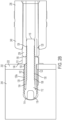
- the first mandrel end 114 has passed into the threaded bore 234 and the head portion 110 of the sleeve 102 or the flange 146 can be in forcible contact with the structure 232 at an entrance side 232a ( FIG. 2A ) of the structure 232.
- the forcible contact between the head portion 110 or flange 146 and the structure 232 can limit further axial movement of the sleeve 102 into the threaded bore 234.
- a collet 238 of the installation tool 236 can engage the pull region 120 of the blind fastener 100.
- the collet 238 can be configured to forcibly contact an anvil 240 of the installation tool 236. The forcible contact can close the collet 238 around the pull region 120 where the collet 238 forcibly contacts the pull region 120.
- the collet 238 can apply a force to the pull region 120 of the mandrel 112.
- the collet 238 can move the mandrel 112 independently of the sleeve 102.
- the collet 238 can retract within the installation tool 236 and move the mandrel 112 as the collet 238 retracts due to the contact between the pull region 120 and the collet 238.
- the anvil 240 can forcibly contact the second sleeve end 106 (e.g., head portion 110).
- the forcible contact between the second sleeve end 106 and the anvil 240 can move the second mandrel end 116 in a vector different than a vector of a force applied to the second sleeve end 106.
- the installation tool 236 can move the pull region 120 distal from the head portion 110 utilizing the collet 238 of the installation tool 236.
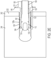
- the first sleeve end 104 and/or the elongate portion 128 can be deformed responsive to forcible contact from mandrel 112.
- the first sleeve end 104 and/or elongate portion 128 can be deformed into threads of the threaded bore 234 responsive to forcible contact between the enlarged portion 118 and the sleeve 102.
- the first sleeve end 104 and elongate portion 128 can be expanded and form external threads corresponding to the threads of the threaded bore 234 responsive to the forcible contact.
- the enlarged portion 118 can be deformed in order to be received by the cavity 108.
- the enlarged portion 118 can be received by the cavity 108 of the sleeve 102 by reducing the diameter, d 2 , of the enlarged portion 118.
- the second sleeve end 106 can be swaged onto the shank region 122 on the entrance side 232a of the structure 232 responsive to forcible contact from the anvil 240.
- the head portion 110 can be swaged onto the shank region 122.
- the swaging of the second sleeve end 106 and/or deformation of the first sleeve end 104 and/or elongate portion 128 can secure at least a portion of the blind fastener 100 in the structure 232. In that way, for example, the first layer 242 and second layer 244 of the structure 232 are secured together.
- the mandrel 112 may not fracture after installation into the structure 232, or as shown in FIG. 2D , the mandrel 112 may fracture along breakneck groove 150 after installation into the structure 232 in a fourth configuration of the blind fastener 100 and the structure 232.
- the blind fastener 100 can be removed from the threaded bore 234 by rotating the blind fastener 100. For example, a torque can be applied to the head portion 110 of the blind fastener 100.
- the blind fastener can be removed by rotating the blind fastener 100 in a counterclockwise direction (when viewing from the second sleeve end 106 of the sleeve 102 to the first sleeve end 104 of the sleeve 102).
- the blind fastener 100 can be removed by rotating the blind fastener 100 in a clockwise direction (when viewing from the second sleeve end 106 of the sleeve 102 to the first sleeve end 104 of the sleeve 102).
- the blind fastener 100 can be at least partially removed from the threaded bore 234.
- the blind fastener 100 can be completely removed from the threaded bore 234 by rotating the blind fastener 100. In that way, for example, the first layer 242 and second layer 244 of the structure 232 may be unsecured.
- the blind fastener 100 can be used in a method for fastening the structure 232.
- the method can comprise inserting the first sleeve end 104 into the threaded bore 234 in the structure 232.
- the collet 238 of the installation tool 236 can engage with the pull region 120 of the blind fastener 100.
- the second sleeve end 106 of the blind fastener 100 can contact the anvil 240 of the installation tool 236.
- the pull region 120 can be moved distal from the head portion 110 utilizing the collet 238 of the installation tool 236.
- the pull region 120 can be moved distal from the head portion 110 utilizing the collet 238 of the installation tool until the mandrel 112 fractures (e.g., at the breakneck groove 150 or other feature configured to fracture).
- the sleeve 102 can be deformed onto the threads of the threaded bore 234, thereby securing at least a portion of the blind fastener 100 in the structure 232.
- Deforming the sleeve 102 can comprise forming external threads on the elongate portion 128, wherein the external threads correspond to the threads of the threaded bore 234.
- the second sleeve end 106 can be swaged onto the shank region 122 of the mandrel 112 on the entrance side 232a of the structure 232.
Landscapes
- Engineering & Computer Science (AREA)
- General Engineering & Computer Science (AREA)
- Mechanical Engineering (AREA)
- Insertion Pins And Rivets (AREA)
- Dowels (AREA)
Claims (12)
- Blindbefestigungselement (100), umfassend:
eine Hülse (102), die für den Einbau in eine Gewindebohrung in einer Struktur angepasst ist, die Hülse umfassend:einen Kopfabschnitt (110), umfassend zumindest ein zum Aufnehmen eines Drehmoments ausgebildetes Merkmal, wobei das Merkmal aus zumindest einem von einer im Wesentlichen flachen Seite, einer Rippe, einer Keilnut, einer Vertiefung, einer Rändelung, einem Vorsprung, einer Bohrung und einer Lasche ausgewählt ist,ein erstes Hülsenende (104),ein zweites Hülsenende (106),einen länglichen Abschnitt (128), der sich zwischen dem ersten Hülsenende und dem zweiten Hülsenende erstreckt, undeinen Hohlraum (108), der sich von dem ersten Hülsenende zu dem zweiten Hülsenende erstreckt;und einen Dorn (112), der zumindest teilweise durch den Hohlraum der Hülse angeordnet ist, der Dorn umfassend:ein erstes Dornende (114), das angrenzend an das erste Hülsenende angeordnet ist und einen vergrößerten Abschnitt (118) mit einem Durchmesser umfasst, der größer ist als der Durchmesser des Hohlraums, wobei der vergrößerte Abschnitt im Wesentlichen hohl oder axial geteilt ist;wobei der längliche Abschnitt zum zumindest teilweisen Verformen in Gewindegänge der Gewindebohrung ausgelegt ist und der Durchmesser des vergrößerten Abschnitts zum zumindest teilweisen Verringern in Reaktion auf einen zwangsweisen Kontakt zwischen dem vergrößerten Abschnitt und der Hülse ausgelegt ist. - Blindbefestigungselement nach Anspruch 1, wobei der längliche Abschnitt (128) zum Bilden von Außengewinden entsprechend den Gewindegängen der Gewindebohrung in Reaktion auf den gewaltsamen Kontakt ausgelegt ist.
- Blindbefestigungselement nach einem der Ansprüche 1 bis 2, wobei der Dorn (112) einen abgestuften Verriegelungsbereich umfasst; und/oder wobei der Dorn eine Sollbruchnut (150) umfasst.
- Blindbefestigungselement nach einem der Ansprüche 1 bis 3, wobei der Dorn (112) ferner umfasst:ein zweites Dornende (116), umfassend einen Zugbereich (120) und einen sich zwischen dem ersten Dornende (114) und dem zweiten Dornende erstreckenden Schaftbereich (122), wobei der Schaftbereich zumindest teilweise durch den Hohlraum (108) der Hülse (102) angeordnet ist,bevorzugt, wobei der Schaftbereich und/oder der Zugbereich zumindest eines von einem im Allgemeinen glatten Bereich, Gewindegängen, einer ringförmigen Schulter und einer Nut umfasst.
- Blindbefestigungselement nach einem der Ansprüche 1 bis 4, wobei die Hülse (102) im Allgemeinen zylindrisch ist und der Dorn (112) im Allgemeinen zylindrisch ist.
- Blindbefestigungselement nach einem der Ansprüche 1 bis 5, ferner umfassend einen Flansch (146), der angrenzend an den Kopfabschnitt (110) angeordnet ist.
- Blindbefestigungselement nach einem der Ansprüche 1 bis 6, wobei das Blindbefestigungselement zumindest eines von einem Metall, einer Metalllegierung und einem Verbundmaterial umfasst und/oder wobei die Struktur zumindest eines von einem Metall, einer Metalllegierung und einem Verbundmaterial umfasst.
- Blindbefestigungselement nach einem der Ansprüche 1 bis 7, wobei die Struktur als zumindest eines von einem/einer Luft- und Raumfahrtteil oder -komponente, einem/einer Kraftfahrzeugteil oder -komponente, einem/einer Transportteil oder -komponente und einem/einer Bau- und Konstruktionsteil oder -komponente ausgelegt ist.
- Verfahren zur Befestigung, das Verfahren umfassend:
Einführen eines Blindbefestigungselements (100) in eine Gewindebohrung (234) in einer Struktur (232), das Blindbefestigungselement umfassend:eine Hülse (102), die für den Einbau in die Gewindebohrung angepasst ist, die Hülse umfassendeinen Kopfabschnitt (110), umfassend zumindest ein zum Aufnehmen eines Drehmoments ausgebildetes Merkmal, wobei das Merkmal aus zumindest einem von einer im Wesentlichen flachen Seite, einer Rippe, einer Keilnut, einer Vertiefung, einer Rändelung, einem Vorsprung, einer Bohrung und einer Lasche ausgewählt ist,ein erstes Hülsenende (104),ein zweites Hülsenende (106),einen länglichen Abschnitt (128), der sich zwischen dem ersten Hülsenende und dem zweiten Hülsenende erstreckt, undeinen Hohlraum (108), der sich von dem ersten Hülsenende zu dem zweiten Hülsenende erstreckt; undeinen Dorn (112), der ausgelegt ist, zumindest teilweise durch den Hohlraum der Hülse angeordnet zu werden, der Dorn umfassend ein erstes Dornende (114), das angrenzend an das erste Hülsenende angeordnet ist und einen vergrößerten Abschnitt (118) mit einem Durchmesser umfasst, der größer ist als der Durchmesser des Hohlraums, wobei der vergrößerte Abschnitt im Wesentlichen hohl oder axial geteilt ist; undVerformen des länglichen Abschnitts zu Gewindegängen der Gewindebohrung, während ein Durchmesser des vergrößerten Abschnitts zumindest teilweise reduziert wird, wodurch zumindest ein Abschnitt des Blindbefestigungselements in der Struktur gesichert wird. - Verfahren nach Anspruch 9, wobei das Verformen der Hülse (102) ferner das Bilden von Außengewinden auf dem länglichen Abschnitt (128) umfasst, wobei die Außengewinde den Gewindegängen der Gewindebohrung (234) entsprechen.
- Verfahren nach Anspruch 9 oder Anspruch 10, ferner umfassend:
nach dem Einsetzen, zwangsweises Inkontaktbringen des zweiten Hülsenendes (106) des Blindbefestigungselements (100) mit einem Amboss eines Installationswerkzeugs und Bewegen eines Zugbereichs (120) eines zweiten Dornendes (116) des Dorns (112) distal von dem zweiten Hülsenende unter Verwendung des Installationswerkzeugs, bis der Dorn bricht; und bevorzugt Verformen der Hülse (102) auf einer ersten Seite der Struktur (232) und Aufweiten des zweiten Hülsenendes auf einen Schaftbereich (122) des Dorns auf einer gegenüberliegend angeordneten zweiten Seite der Struktur. - Verfahren nach einem der Ansprüche 9 bis 11, wobei die Struktur (232) als zumindest eines von einem/einer Luft- und Raumfahrtteil oder -komponente, einem/einer Kraftfahrzeugteil oder -komponente, einem/einer Transportteil oder -komponente und einem/einer Bau- und Konstruktionsteil oder -komponente ausgelegt ist.
Applications Claiming Priority (1)
| Application Number | Priority Date | Filing Date | Title |
|---|---|---|---|
| PCT/US2019/032349 WO2020231416A1 (en) | 2019-05-15 | 2019-05-15 | Blind fasteners and methods of fastening |
Publications (4)
| Publication Number | Publication Date |
|---|---|
| EP3969764A1 EP3969764A1 (de) | 2022-03-23 |
| EP3969764A4 EP3969764A4 (de) | 2022-11-30 |
| EP3969764B1 true EP3969764B1 (de) | 2024-11-06 |
| EP3969764C0 EP3969764C0 (de) | 2024-11-06 |
Family
ID=73288775
Family Applications (1)
| Application Number | Title | Priority Date | Filing Date |
|---|---|---|---|
| EP19928861.4A Active EP3969764B1 (de) | 2019-05-15 | 2019-05-15 | Blindniete und verfahren zur befestigung |
Country Status (4)
| Country | Link |
|---|---|
| US (1) | US12276294B2 (de) |
| EP (1) | EP3969764B1 (de) |
| ES (1) | ES2994338T3 (de) |
| WO (1) | WO2020231416A1 (de) |
Citations (2)
| Publication number | Priority date | Publication date | Assignee | Title |
|---|---|---|---|---|
| JPS5122963A (ja) * | 1974-08-16 | 1976-02-24 | Japan Drive It | Kochakuhoho |
| US20170218996A1 (en) * | 2014-10-31 | 2017-08-03 | Newfrey Llc | Fastening structure and fastening method |
Family Cites Families (20)
| Publication number | Priority date | Publication date | Assignee | Title |
|---|---|---|---|---|
| US3412639A (en) * | 1965-05-24 | 1968-11-26 | Bobbie S. Sauter | Expansible threaded fastener |
| CA995500A (en) * | 1972-04-17 | 1976-08-24 | George Siebol | Blind rivet with recessed expanding head |
| US4407619A (en) * | 1979-09-20 | 1983-10-04 | Olympic Fastening Systems | Blind fastener with deformable clamping means |
| US4863325A (en) * | 1982-09-28 | 1989-09-05 | Huck Manufacturing Company | Two piece blind fastener with lock spindle construction |
| DE3336157C2 (de) | 1983-10-05 | 1997-08-21 | Fichtel & Sachs Ag | Ausbildung eines Sack- bzw. Durchgangslochs für Blindnieten und Blindniet hierfür |
| GB8517659D0 (en) * | 1985-07-12 | 1985-08-21 | Avdel Ltd | Self-plugging blind fastener |
| DE3619826A1 (de) | 1986-06-12 | 1987-12-17 | Hirschmann Radiotechnik | Nietverbindung |
| US5006024A (en) * | 1990-03-05 | 1991-04-09 | George Siebol | Dual-lock blind fastener |
| US5397205A (en) * | 1993-12-27 | 1995-03-14 | Ford Motor Company | Rivet fastener and method of installing |
| GB9501849D0 (en) * | 1995-01-31 | 1995-03-22 | Avdel Systems Ltd | Method of fastening members of an assembly |
| US5689873A (en) * | 1996-01-11 | 1997-11-25 | Allfast Fastening Systems, Inc. | Tacking fastener |
| US6719509B1 (en) | 2002-10-04 | 2004-04-13 | Joker Ind Co Ltd | Expansion screw |
| US20050281633A1 (en) * | 2004-06-16 | 2005-12-22 | Huck International, Inc. | Two-piece, corrosion-resistant, locking blind fastener |
| GB2464674C (en) * | 2008-10-20 | 2013-04-03 | Avdel Uk Ltd | Blind fastener |
| JP5649921B2 (ja) * | 2010-11-16 | 2015-01-07 | ポップリベット・ファスナー株式会社 | ブラインドリベット及びその締結方法 |
| JP2017198224A (ja) * | 2014-07-29 | 2017-11-02 | ポップリベット・ファスナー株式会社 | ブラインドリベット及びその締結方法 |
| DE102015009044A1 (de) * | 2015-07-13 | 2017-01-19 | Sfs Intec Holding Ag | Verfahren zur Herstellung einer Verbindung |
| US10710146B2 (en) * | 2016-10-20 | 2020-07-14 | Arconic Inc. | Fastener and fastening system |
| CN208534942U (zh) * | 2018-07-16 | 2019-02-22 | 靖江市恒丰铆钉制造有限公司 | 一种鼓型抽芯铆钉 |
| WO2020162936A1 (en) * | 2019-02-07 | 2020-08-13 | Arconic Inc. | Blind fastener and method of installation thereof |
-
2019
- 2019-05-15 US US17/594,569 patent/US12276294B2/en active Active
- 2019-05-15 ES ES19928861T patent/ES2994338T3/es active Active
- 2019-05-15 EP EP19928861.4A patent/EP3969764B1/de active Active
- 2019-05-15 WO PCT/US2019/032349 patent/WO2020231416A1/en not_active Ceased
Patent Citations (2)
| Publication number | Priority date | Publication date | Assignee | Title |
|---|---|---|---|---|
| JPS5122963A (ja) * | 1974-08-16 | 1976-02-24 | Japan Drive It | Kochakuhoho |
| US20170218996A1 (en) * | 2014-10-31 | 2017-08-03 | Newfrey Llc | Fastening structure and fastening method |
Also Published As
| Publication number | Publication date |
|---|---|
| US12276294B2 (en) | 2025-04-15 |
| WO2020231416A1 (en) | 2020-11-19 |
| ES2994338T3 (en) | 2025-01-22 |
| EP3969764A1 (de) | 2022-03-23 |
| US20220128077A1 (en) | 2022-04-28 |
| EP3969764C0 (de) | 2024-11-06 |
| EP3969764A4 (de) | 2022-11-30 |
Similar Documents
| Publication | Publication Date | Title |
|---|---|---|
| US4089247A (en) | Blind fastener | |
| EP4055285B1 (de) | Mehrteilige befestigungselemente, befestigungsschelle und verfahren zum befestigen | |
| US20240133409A1 (en) | Blind fastener and method of installation thereof | |
| EP4185780B1 (de) | Selbstformendes gewindeblindbefestigungselement | |
| EP3969764B1 (de) | Blindniete und verfahren zur befestigung | |
| AU2024278347A1 (en) | Multi-piece fastener comprising a tapered threaded portion and method of fastening | |
| AU2021264070B2 (en) | Multi-piece fastener including a lockbolt collar assembly and method of fastening | |
| US11841041B1 (en) | Fastening collars, multi-piece fastening systems, and methods of fastening | |
| EP4259944B1 (de) | Befestigungskragen, mehrteilige befestigungselemente und befestigungsverfahren | |
| EP4165315A1 (de) | Fluiddichte blindbefestigungen und befestigungsverfahren | |
| US20250084884A1 (en) | Fastening collars, multi-piece fasteners, and methods for fastening | |
| WO2025014592A1 (en) | Fastening pins, multi-piece fasteners, and methods for fastening | |
| CN117716137A (zh) | 紧固套环、多件式紧固件以及用于紧固的方法 |
Legal Events
| Date | Code | Title | Description |
|---|---|---|---|
| STAA | Information on the status of an ep patent application or granted ep patent |
Free format text: STATUS: THE INTERNATIONAL PUBLICATION HAS BEEN MADE |
|
| PUAI | Public reference made under article 153(3) epc to a published international application that has entered the european phase |
Free format text: ORIGINAL CODE: 0009012 |
|
| STAA | Information on the status of an ep patent application or granted ep patent |
Free format text: STATUS: REQUEST FOR EXAMINATION WAS MADE |
|
| 17P | Request for examination filed |
Effective date: 20211110 |
|
| AK | Designated contracting states |
Kind code of ref document: A1 Designated state(s): AL AT BE BG CH CY CZ DE DK EE ES FI FR GB GR HR HU IE IS IT LI LT LU LV MC MK MT NL NO PL PT RO RS SE SI SK SM TR |
|
| DAV | Request for validation of the european patent (deleted) | ||
| DAX | Request for extension of the european patent (deleted) | ||
| A4 | Supplementary search report drawn up and despatched |
Effective date: 20221103 |
|
| RIC1 | Information provided on ipc code assigned before grant |
Ipc: F16B 13/06 20060101ALI20221027BHEP Ipc: F16B 5/02 20060101ALI20221027BHEP Ipc: F16B 19/10 20060101AFI20221027BHEP |
|
| STAA | Information on the status of an ep patent application or granted ep patent |
Free format text: STATUS: EXAMINATION IS IN PROGRESS |
|
| 17Q | First examination report despatched |
Effective date: 20240209 |
|
| GRAP | Despatch of communication of intention to grant a patent |
Free format text: ORIGINAL CODE: EPIDOSNIGR1 |
|
| STAA | Information on the status of an ep patent application or granted ep patent |
Free format text: STATUS: GRANT OF PATENT IS INTENDED |
|
| GRAS | Grant fee paid |
Free format text: ORIGINAL CODE: EPIDOSNIGR3 |
|
| INTG | Intention to grant announced |
Effective date: 20240829 |
|
| GRAA | (expected) grant |
Free format text: ORIGINAL CODE: 0009210 |
|
| STAA | Information on the status of an ep patent application or granted ep patent |
Free format text: STATUS: THE PATENT HAS BEEN GRANTED |
|
| AK | Designated contracting states |
Kind code of ref document: B1 Designated state(s): AL AT BE BG CH CY CZ DE DK EE ES FI FR GB GR HR HU IE IS IT LI LT LU LV MC MK MT NL NO PL PT RO RS SE SI SK SM TR |
|
| REG | Reference to a national code |
Ref country code: GB Ref legal event code: FG4D |
|
| REG | Reference to a national code |
Ref country code: CH Ref legal event code: EP |
|
| REG | Reference to a national code |
Ref country code: DE Ref legal event code: R096 Ref document number: 602019061766 Country of ref document: DE |
|
| REG | Reference to a national code |
Ref country code: IE Ref legal event code: FG4D |
|
| U01 | Request for unitary effect filed |
Effective date: 20241107 |
|
| U07 | Unitary effect registered |
Designated state(s): AT BE BG DE DK EE FI FR IT LT LU LV MT NL PT RO SE SI Effective date: 20241115 |
|
| REG | Reference to a national code |
Ref country code: ES Ref legal event code: FG2A Ref document number: 2994338 Country of ref document: ES Kind code of ref document: T3 Effective date: 20250122 |
|
| PG25 | Lapsed in a contracting state [announced via postgrant information from national office to epo] |
Ref country code: HR Free format text: LAPSE BECAUSE OF FAILURE TO SUBMIT A TRANSLATION OF THE DESCRIPTION OR TO PAY THE FEE WITHIN THE PRESCRIBED TIME-LIMIT Effective date: 20241106 Ref country code: IS Free format text: LAPSE BECAUSE OF FAILURE TO SUBMIT A TRANSLATION OF THE DESCRIPTION OR TO PAY THE FEE WITHIN THE PRESCRIBED TIME-LIMIT Effective date: 20250306 |
|
| PG25 | Lapsed in a contracting state [announced via postgrant information from national office to epo] |
Ref country code: NO Free format text: LAPSE BECAUSE OF FAILURE TO SUBMIT A TRANSLATION OF THE DESCRIPTION OR TO PAY THE FEE WITHIN THE PRESCRIBED TIME-LIMIT Effective date: 20250206 |
|
| PG25 | Lapsed in a contracting state [announced via postgrant information from national office to epo] |
Ref country code: GR Free format text: LAPSE BECAUSE OF FAILURE TO SUBMIT A TRANSLATION OF THE DESCRIPTION OR TO PAY THE FEE WITHIN THE PRESCRIBED TIME-LIMIT Effective date: 20250207 |
|
| PG25 | Lapsed in a contracting state [announced via postgrant information from national office to epo] |
Ref country code: PL Free format text: LAPSE BECAUSE OF FAILURE TO SUBMIT A TRANSLATION OF THE DESCRIPTION OR TO PAY THE FEE WITHIN THE PRESCRIBED TIME-LIMIT Effective date: 20241106 |
|
| PG25 | Lapsed in a contracting state [announced via postgrant information from national office to epo] |
Ref country code: RS Free format text: LAPSE BECAUSE OF FAILURE TO SUBMIT A TRANSLATION OF THE DESCRIPTION OR TO PAY THE FEE WITHIN THE PRESCRIBED TIME-LIMIT Effective date: 20250206 |
|
| U20 | Renewal fee for the european patent with unitary effect paid |
Year of fee payment: 7 Effective date: 20250423 |
|
| PG25 | Lapsed in a contracting state [announced via postgrant information from national office to epo] |
Ref country code: SM Free format text: LAPSE BECAUSE OF FAILURE TO SUBMIT A TRANSLATION OF THE DESCRIPTION OR TO PAY THE FEE WITHIN THE PRESCRIBED TIME-LIMIT Effective date: 20241106 |
|
| PGFP | Annual fee paid to national office [announced via postgrant information from national office to epo] |
Ref country code: ES Payment date: 20250602 Year of fee payment: 7 Ref country code: GB Payment date: 20250423 Year of fee payment: 7 |
|
| PG25 | Lapsed in a contracting state [announced via postgrant information from national office to epo] |
Ref country code: SK Free format text: LAPSE BECAUSE OF FAILURE TO SUBMIT A TRANSLATION OF THE DESCRIPTION OR TO PAY THE FEE WITHIN THE PRESCRIBED TIME-LIMIT Effective date: 20241106 |
|
| PG25 | Lapsed in a contracting state [announced via postgrant information from national office to epo] |
Ref country code: CZ Free format text: LAPSE BECAUSE OF FAILURE TO SUBMIT A TRANSLATION OF THE DESCRIPTION OR TO PAY THE FEE WITHIN THE PRESCRIBED TIME-LIMIT Effective date: 20241106 |
|
| PLBE | No opposition filed within time limit |
Free format text: ORIGINAL CODE: 0009261 |
|
| STAA | Information on the status of an ep patent application or granted ep patent |
Free format text: STATUS: NO OPPOSITION FILED WITHIN TIME LIMIT |
|
| 26N | No opposition filed |
Effective date: 20250807 |