EP3969745B9 - Verfahren zur herstellung eines zusatzbauteils für eine tragfläche - Google Patents
Verfahren zur herstellung eines zusatzbauteils für eine tragfläche Download PDFInfo
- Publication number
- EP3969745B9 EP3969745B9 EP20734432.6A EP20734432A EP3969745B9 EP 3969745 B9 EP3969745 B9 EP 3969745B9 EP 20734432 A EP20734432 A EP 20734432A EP 3969745 B9 EP3969745 B9 EP 3969745B9
- Authority
- EP
- European Patent Office
- Prior art keywords
- aerofoil
- trailing edge
- peak
- component
- slit
- Prior art date
- Legal status (The legal status is an assumption and is not a legal conclusion. Google has not performed a legal analysis and makes no representation as to the accuracy of the status listed.)
- Active
Links
Images


Classifications
-
- F—MECHANICAL ENGINEERING; LIGHTING; HEATING; WEAPONS; BLASTING
- F03—MACHINES OR ENGINES FOR LIQUIDS; WIND, SPRING, OR WEIGHT MOTORS; PRODUCING MECHANICAL POWER OR A REACTIVE PROPULSIVE THRUST, NOT OTHERWISE PROVIDED FOR
- F03D—WIND MOTORS
- F03D1/00—Wind motors with rotation axis substantially parallel to the air flow entering the rotor
- F03D1/06—Rotors
- F03D1/065—Rotors characterised by their construction elements
- F03D1/0675—Rotors characterised by their construction elements of the blades
-
- F—MECHANICAL ENGINEERING; LIGHTING; HEATING; WEAPONS; BLASTING
- F03—MACHINES OR ENGINES FOR LIQUIDS; WIND, SPRING, OR WEIGHT MOTORS; PRODUCING MECHANICAL POWER OR A REACTIVE PROPULSIVE THRUST, NOT OTHERWISE PROVIDED FOR
- F03D—WIND MOTORS
- F03D1/00—Wind motors with rotation axis substantially parallel to the air flow entering the rotor
- F03D1/06—Rotors
- F03D1/0608—Rotors characterised by their aerodynamic shape
- F03D1/0633—Rotors characterised by their aerodynamic shape of the blades
-
- F—MECHANICAL ENGINEERING; LIGHTING; HEATING; WEAPONS; BLASTING
- F03—MACHINES OR ENGINES FOR LIQUIDS; WIND, SPRING, OR WEIGHT MOTORS; PRODUCING MECHANICAL POWER OR A REACTIVE PROPULSIVE THRUST, NOT OTHERWISE PROVIDED FOR
- F03D—WIND MOTORS
- F03D7/00—Controlling wind motors
- F03D7/02—Controlling wind motors the wind motors having rotation axis substantially parallel to the air flow entering the rotor
- F03D7/0296—Controlling wind motors the wind motors having rotation axis substantially parallel to the air flow entering the rotor to prevent, counteract or reduce noise emissions
-
- F—MECHANICAL ENGINEERING; LIGHTING; HEATING; WEAPONS; BLASTING
- F05—INDEXING SCHEMES RELATING TO ENGINES OR PUMPS IN VARIOUS SUBCLASSES OF CLASSES F01-F04
- F05B—INDEXING SCHEME RELATING TO WIND, SPRING, WEIGHT, INERTIA OR LIKE MOTORS, TO MACHINES OR ENGINES FOR LIQUIDS COVERED BY SUBCLASSES F03B, F03D AND F03G
- F05B2240/00—Components
- F05B2240/20—Rotors
- F05B2240/30—Characteristics of rotor blades, i.e. of any element transforming dynamic fluid energy to or from rotational energy and being attached to a rotor
- F05B2240/304—Details of the trailing edge
- F05B2240/3042—Serrated trailing edge
-
- F—MECHANICAL ENGINEERING; LIGHTING; HEATING; WEAPONS; BLASTING
- F05—INDEXING SCHEMES RELATING TO ENGINES OR PUMPS IN VARIOUS SUBCLASSES OF CLASSES F01-F04
- F05B—INDEXING SCHEME RELATING TO WIND, SPRING, WEIGHT, INERTIA OR LIKE MOTORS, TO MACHINES OR ENGINES FOR LIQUIDS COVERED BY SUBCLASSES F03B, F03D AND F03G
- F05B2250/00—Geometry
- F05B2250/10—Geometry two-dimensional
- F05B2250/18—Geometry two-dimensional patterned
- F05B2250/182—Geometry two-dimensional patterned crenellated, notched
-
- F—MECHANICAL ENGINEERING; LIGHTING; HEATING; WEAPONS; BLASTING
- F05—INDEXING SCHEMES RELATING TO ENGINES OR PUMPS IN VARIOUS SUBCLASSES OF CLASSES F01-F04
- F05B—INDEXING SCHEME RELATING TO WIND, SPRING, WEIGHT, INERTIA OR LIKE MOTORS, TO MACHINES OR ENGINES FOR LIQUIDS COVERED BY SUBCLASSES F03B, F03D AND F03G
- F05B2250/00—Geometry
- F05B2250/10—Geometry two-dimensional
- F05B2250/18—Geometry two-dimensional patterned
- F05B2250/183—Geometry two-dimensional patterned zigzag
-
- F—MECHANICAL ENGINEERING; LIGHTING; HEATING; WEAPONS; BLASTING
- F05—INDEXING SCHEMES RELATING TO ENGINES OR PUMPS IN VARIOUS SUBCLASSES OF CLASSES F01-F04
- F05B—INDEXING SCHEME RELATING TO WIND, SPRING, WEIGHT, INERTIA OR LIKE MOTORS, TO MACHINES OR ENGINES FOR LIQUIDS COVERED BY SUBCLASSES F03B, F03D AND F03G
- F05B2260/00—Function
- F05B2260/96—Preventing, counteracting or reducing vibration or noise
-
- Y—GENERAL TAGGING OF NEW TECHNOLOGICAL DEVELOPMENTS; GENERAL TAGGING OF CROSS-SECTIONAL TECHNOLOGIES SPANNING OVER SEVERAL SECTIONS OF THE IPC; TECHNICAL SUBJECTS COVERED BY FORMER USPC CROSS-REFERENCE ART COLLECTIONS [XRACs] AND DIGESTS
- Y02—TECHNOLOGIES OR APPLICATIONS FOR MITIGATION OR ADAPTATION AGAINST CLIMATE CHANGE
- Y02E—REDUCTION OF GREENHOUSE GAS [GHG] EMISSIONS, RELATED TO ENERGY GENERATION, TRANSMISSION OR DISTRIBUTION
- Y02E10/00—Energy generation through renewable energy sources
- Y02E10/70—Wind energy
- Y02E10/72—Wind turbines with rotation axis in wind direction
Definitions
- the present application relates to a method for forming an add-on component for an aerofoil.
- Aircraft noise is mainly caused by the jet engine and high lift devices during take-off and landing.
- development in the technology of jet engines has seen a reduction in jet noise, but an increase in noise generated by the high bypass-ratio fan blades.
- Wind turbine mechanical noise is mainly caused by the moving parts inside the gearbox and generator.
- the recent development of high precision gear tooth profile designs and acoustic insulation of casings has reduced the source of mechanical noise.
- the aerodynamic noise generated from the wind turbine blade is more difficult to reduce.
- maximum noise levels are currently set at 35-45 dB(A) at 350 m from the wind turbines.
- Aerodynamic noise can emanate from the aerofoils' leading and trailing edges.
- the aerofoil noise is generated either at the leading edge of the blades, through interaction with the atmospheric turbulence, or at the trailing edges, where turbulence in the boundary layer develops on the blade's surface and scatters into sound.
- Leading edge noise and trailing edge noise are different noise sources and not related to each other.
- Trailing edge noise (also commonly referred to self-noise), remains one of the most relevant noise sources related to the aviation and wind turbine industries.
- trailing edge noise reduction can be achieved by use of a simple sawtooth trailing edge.
- noise reduction by a serrated trailing edge is partly related to destructive interference caused by a phase lag mechanism of turbulence noise scattering on the slanted/oblique edge.
- the root of the serrated trailing edge is effective in turbulence noise radiation.
- two noise sources that are displaced by 180° phase angle in the longitudinal direction, such as the leading edge slit case have been shown to be able to maximise the destructive interference for the aerodynamic noise reduction.
- CN 109292076 A1 discloses a low self-noise aerofoil structure having a multi-wavelength serrated trailing edge.
- the aerofoil body is detachably connected to the noise reduction trailing edge plate through a connector.
- WO 2017/220594 A1 discloses a wind turbine blade comprising two or more serrations provided along a section of the trailing edge.
- US 2012/027590 A1 discloses a rotor blade assembly and a method for reducing the noise of a rotor blade for a wind turbine.
- WO 2019/158876 A1 (Safran Aircraft Engines ) discloses a profiled air flow structure comprising a body and acoustically absorbent porous regions.
- US 2017/0174320 discloses systems, methods, and apparatus for actively adjusting the position of one or more propeller blade treatments of a propeller blade of an aerial vehicle during operation of the aerial vehicle.
- US 2017/0022820 A1 Rolls-Royce plc discloses an aerofoil for a gas turbine which has a series of first and second recesses cut into the leading edge of the aerofoil itself.
- an equivalent inventive formula can be used to tune the noise reduction obtainable from an aerofoil having slit serrations (as disclosed in Gruber, Azarpeyvand and Joseph referred to above).
- h' h".
- the shortest distance from the first peak to the first axis may be identical for each of said pair of peaks within the plurality of pairs.
- the third trough of first pair of peaks may be the first trough of a second pair of peaks which is adjacent to said first pair of peaks.
- a method for reducing the amplitude of sound produced at frequency f peak when air flows in a flow direction from the leading edge of an aerofoil over the trailing edge of an aerofoil at freestream velocity U ⁇ includes the steps of:
- the method may additionally include the steps of forming a plurality of components and attaching said plurality of components to said aerofoil. For example, three components may be formed and attached to said aerofoil, the first component proximate the tip of the aerofoil, the second component proximate the middle of the aerofoil and the third component proximate the other end of the aerofoil to the tip.
- the components may be identical. However, in an alternative embodiment said components have different values of h' and/or h".
- the ratio of the gap between adjacent peaks (W) and the spanwise correlation length scale of the turbulent eddies (L y ) is governed by the expression 0.2 ⁇ W/L y ⁇ 0.5.
- a method for reducing the amplitude of sound produced at frequency f peak when air flows in a flow direction from the leading edge of an aerofoil over the trailing edge of an aerofoil at freestream velocity U ⁇ includes the steps of:
- the method may additionally include the steps of forming a plurality of components and attaching said plurality of components to said aerofoil. For example, three components may be formed and attached to said aerofoil, the first component proximate the tip of the aerofoil, the second component proximate the middle of the aerofoil and the third component proximate the other end of the aerofoil to the tip.
- the components may be identical. However, in an alternative embodiment said components have different values of H.
- a method for forming an add-on component for an aerofoil having a leading edge and a trailing edge, said component being formed in order to reduce the amplitude of sound produced at frequency f peak when air flows in a flow direction from the leading edge of the aerofoil over the trailing edge of the component at flow velocity U the method including the steps of:
- a method for reducing the amplitude of sound produced at frequency f peak when air flows in a flow direction from the leading edge of an aerofoil over the trailing edge of an aerofoil at flow velocity U including the steps of providing at least one component which has been formed according to a method as defined above and attaching said component to said aerofoil.
- add-on component for an aerofoil having a leading edge and a trailing edge, said component being formed in order to reduce the amplitude of sound produced at frequency f peak when air flows in a flow direction from the leading edge of the aerofoil over the trailing edge of the component at flow velocity U, the component including
- Double-Rooted Trailing Edge Serration (abbreviated to "DRooTES")
- DRooTES Double-Rooted Trailing Edge Serration
- SRooTES Single Rooted Trailing Edge Serration
- span-wise length of 0.45 m To ensure similar wetted surface areas.
- different chord lengths were used for the baseline and serrated cases.
- the chord-lengths of the un-serrated trailing edge cases (Baseline) were half of the chord lengths for the serrated trailing edges in Slits and Double-Rooted Serrations (DRooTES).
- the SRooTES represents a simple sawtooth trailing edge.
- the aerofoil was constructed in two main parts: the main aerofoil body and the detachable flat plate trailing edge.
- the main aerofoil was manufactured from aluminium alloy with surface pressure taps across the upper and lower surfaces, and a 0.8 mm slot along the trailing edge.
- a detachable, flat plate of 0.8 mm thickness was laser cut to form various trailing edge shapes.
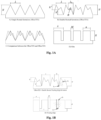
- A illustrates the geometric parameters of the trailing edge flat plate cases. These are defined as the serration amplitude ( H ), serration wavelength ( ⁇ ), root1-root2 longitudinal displacement ( h' ), root2-tip2 longitudinal displacement ( h” ), angle of the serration tip ( ⁇ ) and lateral-displacement serration roots ( ⁇ 0 ). Unless otherwise stated, the root1-root2 longitudinal displacement ( h' ) and root1-root2 lateral displacement ( ⁇ 0 ) are half the amplitude ( H ) and wavelength ( ⁇ ) respectively.
- the geometrical parameters are the slit amplitude (also defined by H ), slit wavelength (also defined by ⁇ ), width of slip tip ( a ) and width of slit gap ( W ).
- H the slit amplitude
- ⁇ the slit wavelength
- W width of slip tip
- W width of slit gap
- a 0.8 mm slot along the rear end of the main aerofoil body allows for insertion of 0.8 mm thickness flat plate trailing edges.
- the ranges of serration amplitude ( H ) and wavelength ( ⁇ ) of the Slit, SRooTES and DRooTES were 5 mm ⁇ H ⁇ 30 mm intervals of 5 mm, and 3 mm ⁇ ⁇ ⁇ 35 mm respectively.
- the root1-root2 lateral displacement and angle of the serration tip of the DRooTES were 1.5 mm ⁇ ⁇ 0 ⁇ 4.5 mm interval of 1.5 mm and 0° ⁇ ⁇ ⁇ 84.3°.
- the Baseline trailing edge was half the amplitude of the serrated case, to ensure similar wetted surface area to both SRooTES and DRooTES.
- the Baseline trailing edge would also be assumed to be half the amplitude.
- a coarse sandpaper was permanently applied to the upper and lower surfaces at 30 mm from the aerofoil leading edge to ensure the boundary layers were fully tripped to turbulent.
- the sandpaper strip had a width of 10 mm and a thickness of 0.95 mm.
- the wind tunnel facilities and instrumentation setup for the far-field noise measurement were performed in the aero-acoustics facility at Brunel University London, which consisted of an open jet wind tunnel within an anechoic chamber of 4 m x 5 m x 3.4 m.
- the open jet nozzle dimension was 0.3 m ⁇ 0.1 m (width x height).
- the aerofoil was attached to the side plates flush to the nozzle lips.
- FIG. 1C illustrates the experimental setup of the far-field array.
- a gain of ⁇ 20 dB was applied to each microphone signal through the G.R.A.S. 12AX 4-Channel CCP amplifier.
- the data were acquired using a 16-bit analogue-digital card manufactured by National Instruments.
- the sampling frequency was 40 kHz with a sampling time of 20 seconds.
- the data were windowed and the Power Spectral Density (PSD) of 1 Hz bandwidth was computed from a 1024 points FFT and a 50% overlap time.
- PSD Power Spectral Density
- A illustrates the geometric parameters of the trailing edge flat plate cases.
- these are defined as the serration amplitude ( H ), serration wavelength ( ⁇ ), root1-root2 longitudinal displacement ( h' ), root2-tip2 longitudinal displacement ( h "), angle of the serration tip ( ⁇ ) and lateral-displacement serration roots ( ⁇ 0 ).
- the root1-root2 longitudinal displacement ( h' ) and root1-root2 lateral displacement ( ⁇ 0 ) are normally half the amplitude ( H ) and wavelength ( ⁇ ) respectively.
- the geometrical parameters are the slit amplitude (also defined by H ), slit wavelength (also defined by ⁇ ), width of slip tip ( a ) and width of slit gap ( W ).
- span-wise length of 0.45 m To ensure similar wetted surface areas.
- different chord lengths were used for the baseline and serrated cases.
- the chord-lengths of the un-serrated trailing edge cases (Baseline) were half of the chord lengths for the serrated trailing edges in Slits and Double-Rooted Serrations (DRooTES).
- the SRooTES represents a simple sawtooth trailing edge.
- the aerofoil was constructed in two main parts: the main aerofoil body and the detachable flat plate trailing edge.
- the main aerofoil was manufactured from aluminium alloy with surface pressure taps across the upper and lower surfaces, and a 0.8 mm slot along the trailing edge.
- a detachable, flat plate of 0.8 mm thickness was laser cut to form various trailing edge shapes.
- A illustrates the geometric parameters of the trailing edge flat plate cases. These are defined as the serration amplitude ( H ), serration wavelength ( ⁇ ), root1-root2 longitudinal displacement ( h' ), root2-tip2 longitudinal displacement ( h "), angle of the serration tip ( ⁇ ) and lateral-displacement serration roots ( ⁇ 0 ). Unless otherwise stated, the root1-root2 longitudinal displacement ( h' ) and root1-root2 lateral displacement ( ⁇ 0 ) are half the amplitude ( H ) and wavelength ( ⁇ ) respectively.
- the geometrical parameters are the slit amplitude (also defined by H ), slit wavelength (also defined by ⁇ ), width of slip tip ( a ) and width of slit gap ( W ).
- H the slit amplitude
- ⁇ the slit wavelength
- W width of slip tip
- W width of slit gap
- a 0.8 mm slot along the rear end of the main aerofoil body allows for insertion of 0.8 mm thickness flat plate trailing edges.
- the ranges of serration amplitude ( H ) and wavelength ( ⁇ ) of the Slit, SRooTES and DRooTES were 5 mm ⁇ H ⁇ 30 mm intervals of 5 mm, and 3 mm ⁇ ⁇ ⁇ 35 mm respectively.
- the root1-root2 lateral displacement and angle of the serration tip of the DRooTES were 1.5 mm ⁇ ⁇ 0 ⁇ 4.5 mm interval of 1.5 mm and 0° ⁇ ⁇ ⁇ 84.3°.
- the Baseline trailing edge was half the amplitude of the serrated case, to ensure similar wetted surface area to both SRooTES and DRooTES.
- the Baseline trailing edge would also be assumed to be half the amplitude.
- a coarse sandpaper was permanently applied to the upper and lower surfaces at 30 mm from the aerofoil leading edge to ensure the boundary layers were fully tripped to turbulent.
- the sandpaper strip had a width of 10 mm and a thickness of 0.95 mm.
- the wind tunnel facilities and instrumentation setup for the far-field noise measurement were performed in the aero-acoustics facility at Brunel University London, which consisted of an open jet wind tunnel within an anechoic chamber of 4 m x 5 m x 3.4 m.
- the open jet nozzle dimension was 0.3 m ⁇ 0.1 m (width x height).
- the aerofoil was attached to the side plates flush to the nozzle lips.
- FIG. 1C illustrates the experimental setup of the far-field array.
- a gain of ⁇ 20 dB was applied to each microphone signal through the G.R.A.S. 12AX 4-Channel CCP amplifier.
- the data were acquired using a 16-bit analogue-digital card manufactured by National Instruments.
- the sampling frequency was 40 kHz with a sampling time of 20 seconds.
- the data were windowed and the Power Spectral Density (PSD) of 1 Hz bandwidth was computed from a 1024 points FFT and a 50% overlap time.
- PSD Power Spectral Density
- the results are presented in this section.
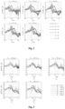
- Figure 2 illustrates a comparison of the sensitivity of slit trailing edges at various H at different freestream velocities, U ⁇ .
- the slit trailing edge can also result in significant degradation in performance, compared to the Baseline trailing edge, at high frequencies up to 5 dB.
- distinctive peaks of noise reduction ⁇ PWL achieved by individual slit trailing edges appears not to follow a trend of slit amplitude H across various U ⁇ .
- the individual slit trailing edges observed that the maximum ⁇ PWL exhibited a relationship f to U ⁇ and to H as follows:
- the acoustic frequency where the maximum noise reduction occurs has a relationship to freestream velocity and the longitudinal displacement between either end of the slit (root and tip), H.
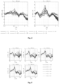
- Figure 3 illustrates whether application of non-dimensional frequency against the broadband noise reduction of the slit trailing edge, at various slit amplitude ( H ), can be generalised.
- perfect destructive interference occurs when the acoustic radiations are at 180° out-of-phase between two sources, resulting in cancellation of the acoustic radiation.
- Figure 1B shows the initial hypothesis of the destructive interference between two sources at the root and tip of the slit trailing edge.
- Figure 3 clearly demonstrates that all the peaks ⁇ PWL pertaining to the slit configurations are followed by a significant dip of ⁇ PWL (noise increase) at St ⁇ 1, which is twice the value for the Strouhal number for maximum noise reduction discussed in the previous paragraph.
- ⁇ PWL noise increase
- Figure 4 shows a comparison of the sensitivity of non-dimensional frequency at various ⁇ of the slit trailing edges, where the slit width, W, was kept constant at 0.3 mm.
- the results shown in Figure 4 are observed at all freestream velocities.
- the effects of acoustic interference mechanism were still observable at the largest ⁇ slit trailing edge cases, however, the effects of the mechanism were greatly weakened in comparison to the smallest ⁇ .
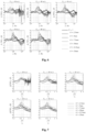
- Figure 5 presents a comparison of the broadband noise radiation for slit trailing edges at different aspect ratios of W / ⁇ , where ⁇ was kept constant at 3 mm.
- the results clearly demonstrate that as W increases, significant degradation of the noise performance (negative ⁇ PWL) occurs at low-to-mid frequencies across all freestream velocities.
- the slit geometry becomes less compact, and eventually exceeds the spanwise integral length scale of the turbulent eddies. In this case, the slit at the root region slowly reverts to a straight trailing edge noise mechanism, which in turn diminishes the noise reduction capability.
- the noise reduction is subjected to the boundary condition of the ratio between the slit gap ( W ), and the incoming spanwise correlation length scale of the turbulent eddies (L y ) near the trailing edge. It is found from the experiments that the optimal condition for noise reduction at f peak to occur is approximately when 0.2 ⁇ W/L y ⁇ 0.5.
- the lower and upper limits of W/L y may fluctuate depending on the flow condition (such as Reynolds numbers, Mach numbers, etc).
- FIG. 6 presents a comparison of the broadband noise reduction (as well as noise increase) by the DRooTES against the baseline trailing edge at different root-to-root amplitude, h ' (see Figure 1B ).
- the smallest h' 2.5 mm exhibits noise reduction against the baseline trailing edge only at high frequency.
- DRooTES exhibit an increase in noise, up to 2 dB, with the increase in amplitude.
- ⁇ 2 ⁇ f.
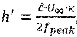
- u c is the same definition used for the slit trailing edge earlier, which is the convection speed of the turbulent eddies after subjected to the interaction with the pressure-driven secondary flow.
- the empirical factor ⁇ h " h ′ 0.4 , accounts for the possible non-equal value between the h' and h" in the frequency scaling for the DRooTES.
- the best performer based on the maximum ⁇ PWL was the slit trailing edge case with reduction up to 4.8 dB in comparison to the baseline trailing edge.
- the DRooTES produced significant broadband noise reduction up to 4.5 dB across a significant greater frequency range, 100 Hz ⁇ f ⁇ 4 kHz, at all freestream velocities in comparison to the slit trailing edge. This compares to the slit achieving reduction across a small frequency range of 100 ⁇ f ⁇ 1.5 kHz based on the freestream velocity.
- the worst case is the SRooTES which produced the least noise reduction at the low to mid frequency.
- the SRooTES produced the least noise increase in comparison to DRooTES and slit trailing edge.
- the slit trailing edge produced the greatest noise increase, followed by DRooTES.
- the best performer was the DRooTES with the largest noise reduction up to 7.2 dB.
- the DRooTES produced the smallest noise increase and noise reduction across all frequency ranges in comparison to baseline.
- the SRooTES produced similar noise reduction across the low to mid frequency range, however, it produced the greatest noise increase.
- the slit trailing edge produced significant reduction at specific frequencies at the low to mid frequency range and produced similar reductions to the DRooTES at high frequency.
Landscapes
- Engineering & Computer Science (AREA)
- Life Sciences & Earth Sciences (AREA)
- Sustainable Development (AREA)
- Sustainable Energy (AREA)
- Chemical & Material Sciences (AREA)
- Combustion & Propulsion (AREA)
- Mechanical Engineering (AREA)
- General Engineering & Computer Science (AREA)
- Physics & Mathematics (AREA)
- Fluid Mechanics (AREA)
- Structures Of Non-Positive Displacement Pumps (AREA)
- Wind Motors (AREA)
Claims (9)
- Verfahren zum Bilden einer Zusatzkomponente für eine Tragfläche mit einer Vorderkante und einer Hinterkante, wobei die Komponente gebildet wird, um die Amplitude des Schalls zu verringern, der mit der Frequenz fpeak erzeugt wird, wenn Luft in einer Strömungsrichtung von der Vorderkante der Tragfläche über die Hinterkante der Komponente mit einer Freistromgeschwindigkeit U∞ strömt, wobei das Verfahren die folgenden Schritte umfasst:(a) Auswählen einer Frequenz f peak des Schalls, der verringert werden soll;(b) Auswählen einer Freistromgeschwindigkeit U∞ der Luft;(c) Bereitstellen einer Komponente mit einer Verbindungskante zum Verbinden mit einer Hinterkante einer Tragfläche und einer Hinterkante gegenüber der Verbindungskante;(d) der Hinterkante der Komponente die Form mehrerer Paare von Erhebungen geben, wobei jedes der Paare eine erste Senke, eine erste Erhebung, eine zweite Senke, eine zweite Erhebung, die einen größeren Abstand von der Verbindungskante hat als die erste Erhebung, und eine dritte Senke aufweist, wobei die erste Senke auf einer Seite der ersten Erhebung liegt, die zweite Senke zwischen der ersten und der zweiten Erhebung liegt und die dritte Senke auf der anderen Seite der zweiten Erhebung als die zweite Senke liegt,(e) wobei die ersten und dritten Senken jedes Paares von Erhebungen im Wesentlichen auf einer ersten Achse liegen, die zweiten Senken jedes Paares von Erhebungen im Wesentlichen auf einer zweiten Achse liegen, und die zweiten Erhebungen jedes Paares von Erhebungen auf einer dritten Achse liegen,(f) und dadurch gekennzeichnet, dass die Komponente gemäß der Formel:wobei h' der kürzeste Abstand zwischen der ersten Achse und der zweiten Achse ist, h" der kürzeste Abstand zwischen der zweiten und der dritten Achse ist, fpeak die Frequenz des zu verringernden Schalls ist, und U∞ die Freistromgeschwindigkeit in Strömungsrichtung der über die Hinterkante der Komponente strömenden Luft ist.

- Verfahren gemäß Anspruch 1, wobei h' = h".
- Verfahren gemäß Anspruch 1 oder 2, wobei der kürzeste Abstand zwischen der ersten Erhebung und der ersten Achse für jedes Paar von Erhebungen innerhalb der mehreren Paare identisch ist.
- Verfahren gemäß einem der vorangehenden Ansprüche, wobei die dritte Senke des ersten Paares von Erhebungen die erste Senke eines zweiten Paares von Erhebungen ist, das an das erste Paar von Erhebungen angrenzt.
- Verfahren zum Verringern der Amplitude des Schalls, der mit der Frequenz fpeak erzeugt wird, wenn Luft in einer Strömungsrichtung von der Vorderkante einer Tragfläche über die Hinterkante einer Tragfläche mit der Freistromgeschwindigkeit U∞ strömt, wobei das Verfahren die folgenden Schritte umfasst:(a) Bilden einer Zusatzkomponente für eine Tragfläche gemäß einem Verfahren gemäß einem der Ansprüche 1 bis 4 und(b) Anbringen der Komponente an der Tragfläche.
- Verfahren gemäß Anspruch 5, umfassend die Schritte des Ausbildens einer Mehrzahl von Bauteilen und des Anbringens der mehreren Bauteile an der Tragfläche.
- Verfahren gemäß Anspruch 6, wobei drei Komponenten gebildet und an der Tragfläche angebracht werden, die erste Komponente in der Nähe der Spitze der Tragfläche, die zweite Komponente in der Nähe der Mitte der Tragfläche und die dritte Komponente in der Nähe des anderen Endes der Tragfläche als der Spitze.
- Verfahren gemäß Anspruch 6 oder 7, wobei die Komponenten identisch sind.
- Verfahren gemäß Anspruch 6 oder 7, wobei die Komponenten unterschiedliche Werte von h' und/oder h" aufweisen.
Applications Claiming Priority (2)
| Application Number | Priority Date | Filing Date | Title |
|---|---|---|---|
| GBGB1906920.2A GB201906920D0 (en) | 2019-05-16 | 2019-05-16 | Method of reducing noise from an aerofoil |
| PCT/GB2020/051178 WO2020229829A2 (en) | 2019-05-16 | 2020-05-14 | A method for forming an add-on component for an aerofoil |
Publications (4)
| Publication Number | Publication Date |
|---|---|
| EP3969745A2 EP3969745A2 (de) | 2022-03-23 |
| EP3969745B1 EP3969745B1 (de) | 2024-07-03 |
| EP3969745C0 EP3969745C0 (de) | 2024-07-03 |
| EP3969745B9 true EP3969745B9 (de) | 2024-11-06 |
Family
ID=67385138
Family Applications (1)
| Application Number | Title | Priority Date | Filing Date |
|---|---|---|---|
| EP20734432.6A Active EP3969745B9 (de) | 2019-05-16 | 2020-05-14 | Verfahren zur herstellung eines zusatzbauteils für eine tragfläche |
Country Status (5)
| Country | Link |
|---|---|
| US (1) | US11808246B2 (de) |
| EP (1) | EP3969745B9 (de) |
| CN (1) | CN113825901B (de) |
| GB (1) | GB201906920D0 (de) |
| WO (1) | WO2020229829A2 (de) |
Families Citing this family (4)
| Publication number | Priority date | Publication date | Assignee | Title |
|---|---|---|---|---|
| CN115803520A (zh) * | 2020-06-29 | 2023-03-14 | 维斯塔斯风力系统有限公司 | 风力涡轮机 |
| EP4623201A1 (de) * | 2022-11-23 | 2025-10-01 | Biomerenewables Inc. | Struktur mit verzahnungen, die dazu angepasst sind, eine fluidumgebung zu durchqueren |
| EP4634525A1 (de) * | 2022-12-16 | 2025-10-22 | LM Wind Power A/S | Windturbinenschaufel mit einem austrittskantenabschnitt mit einer vielzahl von schlitzen mit variierenden längen |
| WO2025232954A1 (en) * | 2024-05-10 | 2025-11-13 | Vestas Wind Systems A/S | Wind turbine blade |
Family Cites Families (10)
| Publication number | Priority date | Publication date | Assignee | Title |
|---|---|---|---|---|
| CN101603514A (zh) * | 2009-07-03 | 2009-12-16 | 吉林大学 | 风力发电机仿生耦合桨叶 |
| US8414261B2 (en) | 2011-05-31 | 2013-04-09 | General Electric Company | Noise reducer for rotor blade in wind turbine |
| US9670901B2 (en) * | 2014-03-21 | 2017-06-06 | Siemens Aktiengesellschaft | Trailing edge modifications for wind turbine airfoil |
| GB201512688D0 (en) | 2015-07-20 | 2015-08-26 | Rolls Royce Plc | Aerofoil |
| CN106704259A (zh) * | 2015-08-03 | 2017-05-24 | 江森自控楼宇设备科技(无锡)有限公司 | 叶片 |
| US10259562B2 (en) | 2015-12-18 | 2019-04-16 | Amazon Technologies, Inc. | Propeller blade trailing edge fringes for improved sound control |
| MA42097B1 (fr) * | 2016-02-12 | 2019-05-31 | Lm Wp Patent Holding As | Panneau de bord de fuite dentelé pour une pale d'éolienne |
| CN109563804B (zh) | 2016-06-20 | 2021-07-06 | Lm风力发电国际技术有限公司 | 带有尖端锯齿的风力涡轮机叶片 |
| FR3078099B1 (fr) | 2018-02-16 | 2020-09-11 | Safran Aircraft Engines | Structure a profil en serrations avec des surfaces traitees |
| CN109292076A (zh) | 2018-11-15 | 2019-02-01 | 哈尔滨工业大学 | 一种具有多波长锯齿尾缘的低自噪声翼型结构 |
-
2019
- 2019-05-16 GB GBGB1906920.2A patent/GB201906920D0/en not_active Ceased
-
2020
- 2020-05-14 WO PCT/GB2020/051178 patent/WO2020229829A2/en not_active Ceased
- 2020-05-14 EP EP20734432.6A patent/EP3969745B9/de active Active
- 2020-05-14 CN CN202080035940.8A patent/CN113825901B/zh active Active
-
2021
- 2021-11-15 US US17/526,808 patent/US11808246B2/en active Active
Also Published As
| Publication number | Publication date |
|---|---|
| GB201906920D0 (en) | 2019-07-03 |
| WO2020229829A3 (en) | 2020-12-17 |
| US20220074383A1 (en) | 2022-03-10 |
| CN113825901B (zh) | 2024-12-17 |
| WO2020229829A2 (en) | 2020-11-19 |
| CN113825901A (zh) | 2021-12-21 |
| EP3969745A2 (de) | 2022-03-23 |
| US11808246B2 (en) | 2023-11-07 |
| EP3969745B1 (de) | 2024-07-03 |
| EP3969745C0 (de) | 2024-07-03 |
Similar Documents
| Publication | Publication Date | Title |
|---|---|---|
| US11808246B2 (en) | Method for forming an add-on component for an aerofoil | |
| US10301942B2 (en) | Aerofoil | |
| Gruber et al. | An experimental investigation of novel trailing edge geometries on airfoil trailing edge noise reduction | |
| Gruber et al. | On the mechanisms of serrated airfoil trailing edge noise reduction | |
| Chong et al. | Airfoil self noise reduction by non-flat plate type trailing edge serrations | |
| Oerlemans et al. | Prediction of wind turbine noise and validation against experiment | |
| US11105344B2 (en) | Aerofoil | |
| Gruber et al. | Airfoil trailing edge noise reduction by the introduction of sawtooth and slitted trailing edge geometries | |
| Oerlemans | Wind turbine noise: primary noise sources | |
| Gruber et al. | Noise reduction using combined trailing edge and leading edge serrations in a tandem airfoil experiment | |
| Chong et al. | On the effect of leading edge serrations on aerofoil noise production | |
| Ayton et al. | Spanwise varying porosity for the enhancement of leading-edge noise reduction | |
| Finez et al. | Broadband noise reduction of linear cascades with trailing edge serrations | |
| Talboys et al. | A parametric study of the effect of self-oscillating trailing-edge flaplets on aerofoil self-noise | |
| Chong et al. | On the airfoil self-noise reduction by trailing edge serrations of non-insertion type | |
| Woodhead et al. | On the double-rooted trailing edge serration | |
| Wills et al. | Airfoil noise reduction produced by leading edge serrations | |
| Salze et al. | Noise reduction of aero-engines using innovative stators with leading edge features | |
| Guidati et al. | Design of reduced noise airfoils for wind turbines | |
| Juknevicius et al. | Leading edge noise reduction of thin aerofoil by the straight and curved serrations of the add-on type | |
| McKinzie Jr et al. | Analysis of noise produced by jet impingement near the trailing edge of a flat and a curved plate | |
| Biedermann et al. | Noise source identification of aerofoils subjected to leading edge serrations using phased array beamforming | |
| Clair et al. | Turbulence interaction noise from a rectilinear cascade of airfoils and effects of porous material inclusions | |
| Lacagnina et al. | Leading edge serrations for the reduction of aerofoil separation self-noise | |
| Sokolenko et al. | Physics of Acoustic Excitation on Boundary Layer Development |
Legal Events
| Date | Code | Title | Description |
|---|---|---|---|
| STAA | Information on the status of an ep patent application or granted ep patent |
Free format text: STATUS: UNKNOWN |
|
| STAA | Information on the status of an ep patent application or granted ep patent |
Free format text: STATUS: THE INTERNATIONAL PUBLICATION HAS BEEN MADE |
|
| PUAI | Public reference made under article 153(3) epc to a published international application that has entered the european phase |
Free format text: ORIGINAL CODE: 0009012 |
|
| STAA | Information on the status of an ep patent application or granted ep patent |
Free format text: STATUS: REQUEST FOR EXAMINATION WAS MADE |
|
| 17P | Request for examination filed |
Effective date: 20211115 |
|
| AK | Designated contracting states |
Kind code of ref document: A2 Designated state(s): AL AT BE BG CH CY CZ DE DK EE ES FI FR GB GR HR HU IE IS IT LI LT LU LV MC MK MT NL NO PL PT RO RS SE SI SK SM TR |
|
| DAV | Request for validation of the european patent (deleted) | ||
| DAX | Request for extension of the european patent (deleted) | ||
| GRAP | Despatch of communication of intention to grant a patent |
Free format text: ORIGINAL CODE: EPIDOSNIGR1 |
|
| STAA | Information on the status of an ep patent application or granted ep patent |
Free format text: STATUS: GRANT OF PATENT IS INTENDED |
|
| INTG | Intention to grant announced |
Effective date: 20231219 |
|
| GRAS | Grant fee paid |
Free format text: ORIGINAL CODE: EPIDOSNIGR3 |
|
| GRAA | (expected) grant |
Free format text: ORIGINAL CODE: 0009210 |
|
| STAA | Information on the status of an ep patent application or granted ep patent |
Free format text: STATUS: THE PATENT HAS BEEN GRANTED |
|
| AK | Designated contracting states |
Kind code of ref document: B1 Designated state(s): AL AT BE BG CH CY CZ DE DK EE ES FI FR GB GR HR HU IE IS IT LI LT LU LV MC MK MT NL NO PL PT RO RS SE SI SK SM TR |
|
| REG | Reference to a national code |
Ref country code: CH Ref legal event code: EP |
|
| REG | Reference to a national code |
Ref country code: DE Ref legal event code: R096 Ref document number: 602020033337 Country of ref document: DE |
|
| U01 | Request for unitary effect filed |
Effective date: 20240730 |
|
| U07 | Unitary effect registered |
Designated state(s): AT BE BG DE DK EE FI FR IT LT LU LV MT NL PT RO SE SI Effective date: 20240902 |
|
| REG | Reference to a national code |
Ref country code: CH Ref legal event code: PK Free format text: BERICHTIGUNG B9 |
|
| PG25 | Lapsed in a contracting state [announced via postgrant information from national office to epo] |
Ref country code: NO Free format text: LAPSE BECAUSE OF FAILURE TO SUBMIT A TRANSLATION OF THE DESCRIPTION OR TO PAY THE FEE WITHIN THE PRESCRIBED TIME-LIMIT Effective date: 20241003 |
|
| PG25 | Lapsed in a contracting state [announced via postgrant information from national office to epo] |
Ref country code: GR Free format text: LAPSE BECAUSE OF FAILURE TO SUBMIT A TRANSLATION OF THE DESCRIPTION OR TO PAY THE FEE WITHIN THE PRESCRIBED TIME-LIMIT Effective date: 20241004 Ref country code: PL Free format text: LAPSE BECAUSE OF FAILURE TO SUBMIT A TRANSLATION OF THE DESCRIPTION OR TO PAY THE FEE WITHIN THE PRESCRIBED TIME-LIMIT Effective date: 20240703 |
|
| PG25 | Lapsed in a contracting state [announced via postgrant information from national office to epo] |
Ref country code: IS Free format text: LAPSE BECAUSE OF FAILURE TO SUBMIT A TRANSLATION OF THE DESCRIPTION OR TO PAY THE FEE WITHIN THE PRESCRIBED TIME-LIMIT Effective date: 20241103 |
|
| PG25 | Lapsed in a contracting state [announced via postgrant information from national office to epo] |
Ref country code: HR Free format text: LAPSE BECAUSE OF FAILURE TO SUBMIT A TRANSLATION OF THE DESCRIPTION OR TO PAY THE FEE WITHIN THE PRESCRIBED TIME-LIMIT Effective date: 20240703 Ref country code: CZ Free format text: LAPSE BECAUSE OF FAILURE TO SUBMIT A TRANSLATION OF THE DESCRIPTION OR TO PAY THE FEE WITHIN THE PRESCRIBED TIME-LIMIT Effective date: 20240703 |
|
| PG25 | Lapsed in a contracting state [announced via postgrant information from national office to epo] |
Ref country code: ES Free format text: LAPSE BECAUSE OF FAILURE TO SUBMIT A TRANSLATION OF THE DESCRIPTION OR TO PAY THE FEE WITHIN THE PRESCRIBED TIME-LIMIT Effective date: 20240703 Ref country code: RS Free format text: LAPSE BECAUSE OF FAILURE TO SUBMIT A TRANSLATION OF THE DESCRIPTION OR TO PAY THE FEE WITHIN THE PRESCRIBED TIME-LIMIT Effective date: 20241003 |
|
| PG25 | Lapsed in a contracting state [announced via postgrant information from national office to epo] |
Ref country code: RS Free format text: LAPSE BECAUSE OF FAILURE TO SUBMIT A TRANSLATION OF THE DESCRIPTION OR TO PAY THE FEE WITHIN THE PRESCRIBED TIME-LIMIT Effective date: 20241003 Ref country code: PL Free format text: LAPSE BECAUSE OF FAILURE TO SUBMIT A TRANSLATION OF THE DESCRIPTION OR TO PAY THE FEE WITHIN THE PRESCRIBED TIME-LIMIT Effective date: 20240703 Ref country code: NO Free format text: LAPSE BECAUSE OF FAILURE TO SUBMIT A TRANSLATION OF THE DESCRIPTION OR TO PAY THE FEE WITHIN THE PRESCRIBED TIME-LIMIT Effective date: 20241003 Ref country code: IS Free format text: LAPSE BECAUSE OF FAILURE TO SUBMIT A TRANSLATION OF THE DESCRIPTION OR TO PAY THE FEE WITHIN THE PRESCRIBED TIME-LIMIT Effective date: 20241103 Ref country code: HR Free format text: LAPSE BECAUSE OF FAILURE TO SUBMIT A TRANSLATION OF THE DESCRIPTION OR TO PAY THE FEE WITHIN THE PRESCRIBED TIME-LIMIT Effective date: 20240703 Ref country code: GR Free format text: LAPSE BECAUSE OF FAILURE TO SUBMIT A TRANSLATION OF THE DESCRIPTION OR TO PAY THE FEE WITHIN THE PRESCRIBED TIME-LIMIT Effective date: 20241004 Ref country code: ES Free format text: LAPSE BECAUSE OF FAILURE TO SUBMIT A TRANSLATION OF THE DESCRIPTION OR TO PAY THE FEE WITHIN THE PRESCRIBED TIME-LIMIT Effective date: 20240703 Ref country code: CZ Free format text: LAPSE BECAUSE OF FAILURE TO SUBMIT A TRANSLATION OF THE DESCRIPTION OR TO PAY THE FEE WITHIN THE PRESCRIBED TIME-LIMIT Effective date: 20240703 |
|
| PG25 | Lapsed in a contracting state [announced via postgrant information from national office to epo] |
Ref country code: SM Free format text: LAPSE BECAUSE OF FAILURE TO SUBMIT A TRANSLATION OF THE DESCRIPTION OR TO PAY THE FEE WITHIN THE PRESCRIBED TIME-LIMIT Effective date: 20240703 |
|
| PG25 | Lapsed in a contracting state [announced via postgrant information from national office to epo] |
Ref country code: SK Free format text: LAPSE BECAUSE OF FAILURE TO SUBMIT A TRANSLATION OF THE DESCRIPTION OR TO PAY THE FEE WITHIN THE PRESCRIBED TIME-LIMIT Effective date: 20240703 |
|
| PLBE | No opposition filed within time limit |
Free format text: ORIGINAL CODE: 0009261 |
|
| STAA | Information on the status of an ep patent application or granted ep patent |
Free format text: STATUS: NO OPPOSITION FILED WITHIN TIME LIMIT |
|
| 26N | No opposition filed |
Effective date: 20250404 |
|
| U20 | Renewal fee for the european patent with unitary effect paid |
Year of fee payment: 6 Effective date: 20250520 |
|
| PGFP | Annual fee paid to national office [announced via postgrant information from national office to epo] |
Ref country code: GB Payment date: 20250501 Year of fee payment: 6 |