EP3969697B1 - A lock configured to be operated by a key - Google Patents
A lock configured to be operated by a key Download PDFInfo
- Publication number
- EP3969697B1 EP3969697B1 EP20724147.2A EP20724147A EP3969697B1 EP 3969697 B1 EP3969697 B1 EP 3969697B1 EP 20724147 A EP20724147 A EP 20724147A EP 3969697 B1 EP3969697 B1 EP 3969697B1
- Authority
- EP
- European Patent Office
- Prior art keywords
- keyway
- plug
- lock
- key
- shaping element
- Prior art date
- Legal status (The legal status is an assumption and is not a legal conclusion. Google has not performed a legal analysis and makes no representation as to the accuracy of the status listed.)
- Active
Links
Images





Classifications
-
- E—FIXED CONSTRUCTIONS
- E05—LOCKS; KEYS; WINDOW OR DOOR FITTINGS; SAFES
- E05B—LOCKS; ACCESSORIES THEREFOR; HANDCUFFS
- E05B15/00—Other details of locks; Parts for engagement by bolts of fastening devices
- E05B15/08—Key guides; Key pins ; Keyholes; Keyhole finders
-
- E—FIXED CONSTRUCTIONS
- E05—LOCKS; KEYS; WINDOW OR DOOR FITTINGS; SAFES
- E05B—LOCKS; ACCESSORIES THEREFOR; HANDCUFFS
- E05B19/00—Keys; Accessories therefor
- E05B19/0017—Key profiles
- E05B19/0041—Key profiles characterized by the cross-section of the key blade in a plane perpendicular to the longitudinal axis of the key
- E05B19/0047—Key profiles characterized by the cross-section of the key blade in a plane perpendicular to the longitudinal axis of the key with substantially circular or star-shape cross-section
-
- E—FIXED CONSTRUCTIONS
- E05—LOCKS; KEYS; WINDOW OR DOOR FITTINGS; SAFES
- E05B—LOCKS; ACCESSORIES THEREFOR; HANDCUFFS
- E05B19/00—Keys; Accessories therefor
- E05B19/0017—Key profiles
- E05B19/0041—Key profiles characterized by the cross-section of the key blade in a plane perpendicular to the longitudinal axis of the key
- E05B19/007—Key profiles characterized by the cross-section of the key blade in a plane perpendicular to the longitudinal axis of the key with U- or V-shaped cross-section
-
- E—FIXED CONSTRUCTIONS
- E05—LOCKS; KEYS; WINDOW OR DOOR FITTINGS; SAFES
- E05B—LOCKS; ACCESSORIES THEREFOR; HANDCUFFS
- E05B29/00—Cylinder locks and other locks with plate tumblers which are set by pushing the key in
- E05B29/0013—Cylinder locks and other locks with plate tumblers which are set by pushing the key in with rotating plate tumblers
-
- E—FIXED CONSTRUCTIONS
- E05—LOCKS; KEYS; WINDOW OR DOOR FITTINGS; SAFES
- E05B—LOCKS; ACCESSORIES THEREFOR; HANDCUFFS
- E05B29/00—Cylinder locks and other locks with plate tumblers which are set by pushing the key in
- E05B29/0066—Side bar locking
-
- E—FIXED CONSTRUCTIONS
- E05—LOCKS; KEYS; WINDOW OR DOOR FITTINGS; SAFES
- E05B—LOCKS; ACCESSORIES THEREFOR; HANDCUFFS
- E05B35/00—Locks for use with special keys or a plurality of keys ; keys therefor
- E05B35/001—Locks for use with special keys or a plurality of keys ; keys therefor with key identifying function
-
- E—FIXED CONSTRUCTIONS
- E05—LOCKS; KEYS; WINDOW OR DOOR FITTINGS; SAFES
- E05B—LOCKS; ACCESSORIES THEREFOR; HANDCUFFS
- E05B63/00—Locks or fastenings with special structural characteristics
- E05B63/0056—Locks with adjustable or exchangeable lock parts
Definitions
- the present invention relates to a lock configured to be operated by a key with a key shank, which includes at least in a part of its axial length a profile which is closed or semi-closed to define at least one cavity including a key coding.
- Such locks are e.g. known from US 9,920,548 B2 , WO 2016/162363 A1 and WO 2018/041277 A1 of the same applicant.
- the uniqueness of a lock is defined by a number of specific characteristics. This number is limited so that a limited number of unique locks can be provided. It is desirable to increase the number in a simplified manner.
- the document US 3 754 422 A or AU 82322 82 A discloses a cylinder lock comprising a key selection member plate to limit the insertion to specific key profiles only.
- a lock according to claim 1 is provided. Also, a lock system according to claim 11 and a method for manufacturing a lock according to claim 16 are provided. The further claims specify additional embodiments of the lock and the lock system.
- the lock comprises a plug for receiving a key shank and being configured to be accommodated in a housing, the plug being rotatable with respect to the housing in the unlocked state of the lock, the plug including a keyway, which is defined by a predetermined geometry and has a transverse keyway profile including an arcuate portion.
- the lock according to claim 1 comprises also at least one keyway shaping element, which is formed separate from the plug and which is fixed to the plug such that it is immovable relative to the plug when the key shank is inserted into the plug, wherein a protruding portion of the at least one keyway shaping element protrudes into the keyway to redefine its geometry. This allows the configuration of a larger number of unique locks.
- a master lock may be e.g. configured as a lock which includes the at least one keyway shaping element and a slave lock may be configured in the same way, but without the at least one keyway shaping element.
- the master key may e.g. include a wall portion, which, seen in a plane transverse to the longitudinal direction in which the key shank extends, has a shape complementary to the protruding portion of the at least one keyway shaping element.
- the slave key may e.g. include a wall portion, which, seen in a plane transverse to the longitudinal direction in which the key shank extends, has a shape complementary to the keyway without the at least one keyway shaping element.
- keyway shaping element there may be provided more than one keyway shaping element.
- the plug may be provided with two or more keyway shaping elements, each being formed separate from the plug and fixed to the plug such that they are immovable relative to the plug when the key shank is inserted into the plug.
- the protruding portions of the keyway shaping elements protrude into the keyway to redefine its geometry at different locations.
- the keyway shaping elements may be arranged at the same axial position along the axial direction of the keyway. Accordingly, the geometry of the keyway is redefined at locations, which have the same axial position.
- keyway shaping elements may be arranged offset to each other along the axial direction of the keyway. Thereby, the geometry of the keyway is redefined at different axial positions.
- the at least one keyway shaping element is different from a plate having a U-shaped opening.
- the plug for receiving the key shank of the key includes a keyway, which is defined by a predetermined geometry.
- the predetermined geometry has a cross-section which is different from a rectangular shape and/or from a U-shape.
- the lock according to the invention may comprise a plug which is made of one piece.
- the geometry of the keyway may be defined in part by the plug and in part by at least one another component, e.g. by a housing in which the plug is to be accommodated such that it is rotatable in the unlocked state of the lock.
- the geometry of the keyway may be defined fully by the plug.
- the key to operate the lock according to the invention may comprise a key shank which is different from a U-shape and/or a flat shape.
- the key shank is free of a flat blade.
- the profile of the key shank defining the at least one cavity which includes a key coding may include an arcuate wall portion. The profile of the latter may be defined by two opposite side faces, which are arcuate.
- the key to operate the lock according to the invention may comprises a key shank defined by a rigid hollow key body that includes the at least one coding cavity.
- the shape of the key body is such that the key coding is at least in part invisible from outside and/or the shape of the key body is different from a U-shape.
- Fig. 1 shows a cap 10a, which serves for covering the front end of the plug 20 (see Fig. 4 ).
- the cap 10a has a circular cylindrical cross-section and comprises a plate, which is provided at its periphery with an edge element 12a.
- the cap 10a includes a passage 13a which is part of the keyway.
- the edge element 12a has a clearance for receiving a keyway shaping element 16a.
- the latter has the form of a curved ribbon and includes a protruding portion 17a, e.g. in the form of one or more teeth.
- the cap 10a forms an arcuate segment 14a.
- the latter includes at least one slit 15a which runs alongside of the segment 14a.
- the keyway shaping element 16a is immovably attached to the plug 20 by means of the cap 10a.
- the protruding portion 17a of the keyway shaping element 16a extends through the slit 15a into the keyway.
- the keyway 21 defined in the plug 20 has a predetermined profile when seen in a plane perpendicular to the direction into which a key is introduced into the keyway 21.
- the profile of the keyway 21 has an arcuate middle portion 21a connecting two side portions 21b, 21d, each of which including a return portion 21c, 21e.
- the protruding portion 17a of the keyway shaping element 16a redefines said predetermined keyway profile in the plug 20.
- the protruding portion 17a includes teeth and thus has the effect that the outer side of the middle portion 21a of the keyway 21 is no longer defined by a circular line, but by a serrated curve.
- the cap 10a is at least partially arranged within the housing 50.
- the peripheral face 18a of the keyway shaping element 16a is adjacent to the housing 50.
- the latter includes a step 50a which is adjacent to the rearward side of the keyway shaping element 16a.
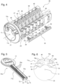
- Fig. 4 shows an example of a lock including the cap 10a, the plug 20, and the validating elements 40.
- the plug 20 comprises a keyway 21, which extends in the insertion direction of the key and which serves for receiving the shank of the key.
- the plug 20 is provided with an axle 11 (see also Fig. 6 ) which extends along a rotation axis 11a and which is attached to the cap 10a.
- the cap 10a may be provided with a peg including a hole for receiving the end of the axle 11, see the peg 5a in Fig. 7 .
- the plug 20 has ribs 27 and slots 23 therebetween, which are arranged tranversally to the rotation axis 11a.
- the validating elements 40 are received in the slots 23 and arranged on the axle 11 in a rotatable manner around the rotation axis 11a.
- the slots 23 are configured such that a portion of a validating element 40 can cooperate with at least one blocking bar 30.
- Each validating element 40 has a first arm 41, which is configured to contact a coding part of a key, and a second arm with a recess 44.
- the validating elements 40 are arranged in an alternating inverted manner so that the first arms 41 point alternatingly to the left and right side.
- the plug 20 includes further a receiving groove 22, which extends alongside of the plug 20 and which serves for receiving the blocking bar 30 in the unlocked state of the lock.
- the blocking bar 30 is preloaded such that in the locked state of the lock it is pushed into a longitudinal groove which is formed in the housing 50 (not shown). Said longitudinal groove extends along a longitudinal direction which is arranged parallel to the rotation axis 11a, around which the plug is rotatable with respect to the housing 50 in the unlocked state of the lock.
- the pushing force is e.g. produced by elastic means, e.g. in the form of one or more springs 34.
- a second receiving groove is formed in the plug 20 opposite to the groove 22 for receiving a second blocking bar in the unlocked state of the lock.
- the second blocking bar is preloaded in a similar way as the blocking bar 30 by means of elastic means, so that, in the locked state of the lock, it is pushed into a longitudinal groove formed in the housing 50.
- the blocking bars are arranged between the plug 20 and the housing 50, whereby a rotation of the components including the cap 10a, the plug 20, the blocking bars 30, and the validating elements 40 with respect to the housing 50 is disabled.
- the validating elements 40 and with it the recesses 44 have the correct position, so that the blocking bar 30 can be received in a receiving space formed by recesses 44 of the validating elements 40 and the receiving groove 22 in the plug 20, and in an analogous manner, the second blocking bar can be received in a receiving space formed by recesses 44 of the validating elements 40 and the second receiving groove in the plug 20.
- the blocking bars are released out of the longitudinal grooves in the housing 50 so that the components including the cap 10a, the plug 20, the blocking bars 30, and the validating elements 40 can be rotated relative to the housing 50 around the rotation axis 11a.
- Fig. 5 shows an example of the key 70a configured to be used with the lock of Fig. 4 .
- the key 70a has a handling part 77, e.g. a bow, and a key shank 71a extending from the handling part 77 and insertable into the keyway 21 of the lock.
- the key shank 71a has a semi-closed profile enclosing at least partially the coding part.
- the key shank 71a has an arcuate middle portion 72a connecting two side portions 73, 75 each being connected to a return portion 74, 76.
- the key shank 71a is shaped towards its middle of the key shank 71a, e.g. U-shaped.
- the portions 73 and 74 as well as the portions 75 and 76 enclose a coding cavity 74' and 76', respectively, in which the key coding is formed, e.g. in form of one or more coding tracks.
- a coding track extends along the key shank 71a and may have e.g. a wavelike course.
- the coding track may be formed e.g. by a line of successive channel portions and/or ridge portions.
- the portions 73-76 prevent that the coding part of the key 70a is visible from outside. This impedes an unauthorized duplication of the key 70a e.g. by producing a copy based on pictures taken from the key 70a.
- the outer face of the key shank 71a is adapted to the profile defined by the keyway shaping element 16a. To this end, the outer face of key shank 71a is formed complementary to the protruding portion 17a of the keyway shaping element 16a.
- the key shank 71a includes grooves 78a for receiving the teeth forming the protruding portion 17a.
- each validating element 40 and with it its recess 44 have a specific angular position. Said position is such that the blocking bars can enter into the recesses 44 when the key 70a has the correct coding.
- Fig. 1 shows one possible example of the protruding portion 17a of the keyway shaping element 16a.
- the protruding portion may include one or more straight portions, one or more curved portions or combinations thereof.
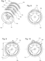
- Fig. 7 shows the keyway shaping element 16a together with other examples of the keyway shaping element 16b, 16c, 16d.
- the protruding portion 17b of the keyway shaping element 16b has teeth which protrude into the keyway 21 formed in the plug 20.
- the number of the teeth and the shape, in particular the height, as well as the position of each tooth may be arbitrarily chosen.
- the protruding portion 17c of the keyway shaping element 16c has an arcuate shape. Its form, in particular the length and the curvature, may be arbitrarily chosen.
- the parameter D denotes the diameter of the circumcircle which encloses the plug 20, wherein the centre of this circumcircle is on the rotation axis 11a.
- the protruding portion 17c is defined by a section of a circle with radius R, wherein the centre c of this circle is chosen to be offset to the rotation axis 11a.
- the protruding portion 17d of the keyway shaping element 16d has a polygonal shape. Its form, in particular the length and the height of a straight section, may be arbitrarily chosen. In the example shown in Fig. 10 , the protruding portion 17d is defined by a number of straight sections of length s, which touch the inscribed circle with diameter d and centre on the rotation axis 11a, wherein d ⁇ D. The inscribed circle is shown in Fig. 10 as a broken line.
- the cap 10a and a keyway shaping element 17a-17d are configured such that the latter can be retained axially in the cap 12a.
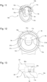
- Fig. 11 shows an example, in which the keyway shaping element 16e is retained radially in the cap 10e.
- the edge element 12e has a clearance 15e so that two ends are formed, each having a recess 9e with an undercut shape.
- the ends of the keyway shaping element 17e is designed complementary to said shape, see also Fig. 12 .
- the protruding portion 17e of the keyway shaping element 16e has a toothed profile.
- the protruding portion 17e of the keyway shaping element 16e may be arbitrarily shaped to redefine the predetermined keyway profile 21a-21e in the plug 20.
- the cap 10e has in the middle a protruding element 5e, which defines part of the shape of the keyway 21 and which is received in a recess 26 formed in the plug 20, see Fig. 13 .
- the rearward side of the keyway shaping element 16e is adjacent to the step 50a in the housing 50.
- the keyway shaping elements 16a-16e are e.g. made of metal.
- the keyway shaping element 16a-16d may be manufactured e.g. by metal injection moulding.
- the keyway shaping element 16e may be manufactured by machining a piece of raw material, e.g. by laser cutting.
- the shank of a key which is useable with a lock having a keyway shaping element 16a-16e has an outer surface which is complementary to the protruding portion 17a-17e.
- the shank of the key may have for instance one or more grooves (see grooves 78a in Fig. 5 ) and/or may have an outer surface defined by one or more curved or straight sections or combinations thereof.
- the keyway shaping element 16a-16e cooperate with the outer surface of the key shank. It is possible to configure the keyway shaping element such that it cooperates with the inner surface of the key shank.
- Fig. 14 shows a cap 10f with the edge element 12f and a keyway shaping element 16f.
- the cap 10f has the passage 13a.
- a protruding element 5f defining part of the keyway 21 and including a slot 6f is formed in the middle of the cap 10f.
- the protruding element 5f has a hole 9f going transversally through the slot 6f for receiving the ends of a pin 7 (see Fig. 15 ).
- the keyway shaping element 16f is formed as a plate. It has a protruding portion 17f to redefine the keyway 21 and a through-hole 19f for fixation to the cap 10f.
- the keyway shaping element 16f is received in the slot 6f and fixed by the pin 7 which goes through holes 9f, 19f.
- the protruding portion 17f protrudes into the passage 13a of the cap 10f and thus into the keyway 21.
- the edge element 12f in Fig. 14 and 15 is shown with a clearance 15f, so that the cap 10f forms there an arcuate segment 14f.
- a keyway shaping element similar to the keyway shaping element 16e may be introduced into the clearance 15f.
- different kinds of keyway shaping elements may be arranged in a combined way on the cap 10f.
- the clearance 15f may be omitted, so that the edge element 12f extends fully around the protruding element 5f. This configuration is shown in Fig. 17 .
- the protruding portion 17f of the keyway shaping element 16f has teeth. Accordingly, the inner surface of the key shank 71f has grooves 78f for engagement with the teeth, see Fig. 17 .
- the plug 20 has a recess 26, in which the protruding element 5f can be received, see Fig. 18 .
- This Fig. 18 shows also the central bore 25 in the plug 20 for receiving the axle 11.
- the protruding portion 17f of the keyway shaping element 17f may be arbitrarily shaped to redefine the predetermined keyway profile in the plug 20.
- the protruding portion may include one or more straight portions, one or more curved portions or combinations thereof.
- Fig. 19 shows further examples of a keyway shaping element 16g, 16h.
- the keyway shaping element 16g has a protruding portion 17g defined by a curved shape.
- the latter may be defined e.g. by a section of a circle, wherein the centre of this circle is chosen to be offset to the rotation axis 11a, so that the protruding portion 17g protrudes from below into the middle portion 21a of the keyway 21.
- the keyway shaping element 16h has a protruding portion 17h with a polygonal shape.
- the keyway shaping element may also be configured such that it can be placed in a slot 23 of the plug 20 and attached to the axle 11 to which the validating elements 40 are attached.
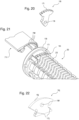
- Fig. 20 shows an example of the keyway shaping element 16i, which is formed as a plate. It has a protruding portion 17i, which may be similar to one of the keyway shaping element 17f, and an end with a hole 19i for attachment to the axle 11.
- Fig. 21 shows the assembled state, in which the keyway shaping element 16i is received in a front slot formed in the plug 20 and attached to the axle 11 (not visible).
- the attachment is such that the keyway shaping element 16i is immovably attached to the plug 20 by means of the axle 11.
- the cap 10i may be configured such that it has a protruding element similar as the protruding element 5e of the keyway shaping 10e.
- the key 71f with the grooves 78f of Fig. 17 may be used to engage with the teeth of the keyway shaping element 16i.
- Fig. 21 the keyway shaping element 16i is positioned in the foremost slot 23 of the plug 20. It is conceivable that the keyway shaping element 16i is received in another slot 23 of the plug 20 and attached there to the axle 11, so that it is positioned within the axial length of the plug 20.
- the length of a groove 78f in the key shank 71f can be chosen in dependency on the position of the keyway shaping element 16i along the plug 20.
- a master and slave lock system may be provided. For instance, a first lock with a keyway shaping element 16i in the foremost slot 23 (in the following "first position") and a second lock with a keyway shaping element 16i within the axial length of the plug 20 (in the following "second position”) may be provided.
- a key with grooves sufficiently long so that they extend at least from the first to the second position can open the first and second lock, whereas a key with shorter grooves can open only the second look, but not the first one, since the end of those shorter grooves will abut against the keyway shaping element 16i in the first position, so that the key shank cannot fully be inserted into the keyway.
- the keyway shaping element may also be configured such that it redefines another portion of the keyway 21 than its middle portion 21a.
- Fig. 22 shows an example of the keyway shaping element 16j, which is formed as a plate having protruding portions 17j at both sides. It has further a hole 19f similar as the keyway shaping element 16f so that it can be fixed by a pin in the slot 6f of cap 10f.
- the shape of the upper part 18j of the keyway shaping element 16j corresponds to the lower part of the middle portion 21a of the keyway 21, so that this part 18j does not protrude into the middle portion 21a, see Fig. 23 .
- the keyway shaping element 16j has on each side a protruding portion 17j protruding into the return portions 21c, 21e of the keyway 21.
- the protruding portions 17j are formed as one or more teeth.
- a key useable with the keyway shaping element 16j has a key shank 71j, in which the outer surface of the return portions 74j, 76j have a shape complementary to the protruding portions 17j.
- the return portions 74j, 76j have grooves 78j for engagement with the teeth of the protruding portions 17j.
- FIG. 24 shows an example, in which the upper part and the sides of the keyway shaping element 16k have protruding portions 17f, 17j.
- the protruding portion 17f corresponds to that of keyway shaping element 16f
- the protruding portions 17j correspond to those of keyway shaping element 16j.
- the keyway shaping element 16j is placed in the slot 6f of cap 10f and attached to the plug 20, so that the protruding portion 17f redefines the middle portion 21a of the keyway 21, and the protruding portions 17j redefine the return portions 21c, 21e of the keyway 21.
- keyway shaping element 16k it is also possible to use more than one keyway shaping element.
- keyway shaping elements 16f and 16j may be combined by means of a cap 10f to the plug 20, which result in the same redefinition of the keyway as the keyway shaping element 16k.
- the thickness of the keyway shaping elements and the thickness of the slot 6f of cap 10f are adapted to each other such that more than one keyway shaping element can be placed in the slot 6f.
- keyway shaping elements are provided at the front end of the keyway 21. It is conceivable to provide one or more keyway shaping elements within the axial length of the keyway 21.
- Fig. 26 shows an example, in which the plug 20 is provided with keyway shaping elements 161, 16m which are arranged within the axial length of the plug 22.
- the plug 20 is covered by a cap 10, which is free of a keyway shaping element and which has the passage 13a.
- the plug 20 has side wings 21b', 21d'.
- Side wing 21b' defines the side portion 21b of the keyway 21
- side wing 21d' defines the side portion 21d of the keyway 21.
- a keyway shaping element 161, 16m is received in a blind hole 24 formed in a side wing 21b', 21d', see also Fig. 27 .
- a keyway shaping element 16l, 16m is a formed by a pin, which is fixed in a blind hole 24 e.g. by press-fitting. The fixation is such that a keyway shaping element 161, 16m does not move relative to the plug 20 when the key shank 71l of a key is inserted into the plug 20.
- the front end of a keyway shaping element 161, 16m forms a protruding portion 17l, 17m which protrudes into the keyway 21 and thereby redefines its geometry.
- a keyway shaping element 161, 16m, its position along the plug 20 and the shape of the protruding portion may vary.
- Fig. 28 shows examples, in which the keyway shaping element 16l has a conical protruding portion 17l, the keyway shaping element 16m has a spherical protruding portion 17m, and the keyway shaping element 16n has a circular cylindrical protruding portion 17n
- a key 70l which is useable with a lock of Fig. 26 , has a key shank 71l including at least one groove 78l, 78m for engagement with the at least one keyway shaping element 17l, 17m.
- the key shank 71l of the key 70l has grooves 78l, 78m which are formed on the side portions 73l, 75l of the key shank 71l.
- the cross-section of the groove 78l, 78m corresponds to the shape, which the corresponding keyway shaping element 17l, 17m has when seen in a side view.
- the groove 78l has a triangular cross-section for engagement with the conical keyway shaping element 17l and the groove 78m has a circular cross-section for engagement with the spherical keyway shaping element 17m.
- a groove configured to cooperate with the keyway shaping element 17n of Fig. 28 would have a rectangular cross-section.
- the length of a groove 78l, 78m is adapted to the position of a keyway shaping element 17l, 17m along the plug 20.
- a keyway shaping element 17l, 17m will be positioned at the closed end of the groove 78l, 78m.
- the plug 20 of Fig. 31 has side wings 21b' and 21d', which enclose an angle of A0, see Fig. 32 .
- Both side wings 21b', 21d' are provided with keyway shaping elements 16o.
- a keyway shaping element 16o has a protruding portion 17o and may e.g. have the shape of the keyway shaping element 16m.
- a key useable with a plug 20 of Fig. 31 has a key shank 71o with side portions 73o, 75o, which are inclined to each other by the reduced angle of B.
- the plug may e.g. provided with keyway shaping elements 17o on only one wing 21b' or 21d', so that the reduced angle is given by A0 - A1.
- the size with which the protruding portions of the keyway shaping elements 17o extend into the keyway 21 may be different on wings 21b' and 21d'.
- the angle A1 shown in Fig. 32 may be different on both sides, e.g. the angle may correspond to A1 on the left-hand side and to A1' on the right-hand side. In this case the reduced angle is given by A0 - A1 - A1'.
- a lock according to Fig. 4 may be a master lock, which can be operated by the key of Fig. 5 .
- a lock which is configured the same as the one of Fig. 4 , but without the keyway shaping element 16a may be considered as a slave lock, which can also be operated by the key of Fig. 5 .
- a key having a key shank as the key of Fig. 5 but without the grooves can operate only the slave lock, but not the master lock, as due to the missing grooves the key shank cannot be inserted in the keyway of the master lock.
- the embodiment as shown in Fig. 32 may define a master lock and the lock of Fig. 32 without the keyway shaping elements 17o may define a slave lock.
- the key 71o of Fig. 32 which has side portions 73o, 75o inclined to each other by the angle B, may be used to operate said master and said slave lock, whereas a key having side portions inclined to each other by the angle A may be used to operate the slave lock only, but not the master lock.
- the keys described here have an arcuate middle portion, on both sides of which a U-shaped wall portion is attached.
- Other profiles are conceivable, in particular those as shown in Fig. 11 to 46c of US 9,920,548 B2 , in Fig. 14 to 17 of WO 2016/162363 A1 and in Fig. 13 of WO 2018/041277 A1 of the same applicant.
- the key shank may at least in a part of its axial length include a profile which is closed or semi-closed to define at least one cavity including a key coding.
- the key shank with the key coding may be manufactured in one piece.
- the at least one cavity is formed such that the key coding is at least in part invisible from outside.
- the profile may have a shape which is different from a U-shape.
Landscapes
- Physics & Mathematics (AREA)
- Electromagnetism (AREA)
- Engineering & Computer Science (AREA)
- Structural Engineering (AREA)
- Lock And Its Accessories (AREA)
Description
- The present invention relates to a lock configured to be operated by a key with a key shank, which includes at least in a part of its axial length a profile which is closed or semi-closed to define at least one cavity including a key coding.
- Such locks are e.g. known from
US 9,920,548 B2 WO 2016/162363 A1 andWO 2018/041277 A1 of the same applicant. The uniqueness of a lock is defined by a number of specific characteristics. This number is limited so that a limited number of unique locks can be provided. It is desirable to increase the number in a simplified manner. The documentUS 3 754 422 A orAU 82322 82 A - It is an object of the present invention to refine the existing locks such that an increased variety of unique configurations are possible.
- For solving this object, a lock according to claim 1 is provided. Also, a lock system according to
claim 11 and a method for manufacturing a lock according to claim 16 are provided. The further claims specify additional embodiments of the lock and the lock system. - According to claim 1 the lock comprises a plug for receiving a key shank and being configured to be accommodated in a housing, the plug being rotatable with respect to the housing in the unlocked state of the lock, the plug including a keyway, which is defined by a predetermined geometry and has a transverse keyway profile including an arcuate portion. The lock according to claim 1 comprises also at least one keyway shaping element, which is formed separate from the plug and which is fixed to the plug such that it is immovable relative to the plug when the key shank is inserted into the plug, wherein a protruding portion of the at least one keyway shaping element protrudes into the keyway to redefine its geometry. This allows the configuration of a larger number of unique locks.
- The provision of at least one keyway shaping elements allows also the provision of master and slave locks. A master lock may be e.g. configured as a lock which includes the at least one keyway shaping element and a slave lock may be configured in the same way, but without the at least one keyway shaping element.
- There may be provided a master key which is configured to operate the master lock as well as the slave lock, and a slave key which is configured to operate the slave lock only. The master key may e.g. include a wall portion, which, seen in a plane transverse to the longitudinal direction in which the key shank extends, has a shape complementary to the protruding portion of the at least one keyway shaping element. The slave key may e.g. include a wall portion, which, seen in a plane transverse to the longitudinal direction in which the key shank extends, has a shape complementary to the keyway without the at least one keyway shaping element.
- There may be provided more than one keyway shaping element. For instance it is conceivable to provide the plug with two or more keyway shaping elements, each being formed separate from the plug and fixed to the plug such that they are immovable relative to the plug when the key shank is inserted into the plug. The protruding portions of the keyway shaping elements protrude into the keyway to redefine its geometry at different locations. The keyway shaping elements may be arranged at the same axial position along the axial direction of the keyway. Accordingly, the geometry of the keyway is redefined at locations, which have the same axial position. In addition to this configuration or alternatively thereto keyway shaping elements may be arranged offset to each other along the axial direction of the keyway. Thereby, the geometry of the keyway is redefined at different axial positions.
- Preferably, the at least one keyway shaping element is different from a plate having a U-shaped opening.
- The plug for receiving the key shank of the key includes a keyway, which is defined by a predetermined geometry. Preferably, the predetermined geometry has a cross-section which is different from a rectangular shape and/or from a U-shape.
- Preferably, the lock according to the invention may comprise a plug which is made of one piece.
- Preferably, the geometry of the keyway may be defined in part by the plug and in part by at least one another component, e.g. by a housing in which the plug is to be accommodated such that it is rotatable in the unlocked state of the lock. Alternatively, the geometry of the keyway may be defined fully by the plug.
- Preferably, the key to operate the lock according to the invention may comprise a key shank which is different from a U-shape and/or a flat shape. Preferably, the key shank is free of a flat blade. The profile of the key shank defining the at least one cavity which includes a key coding may include an arcuate wall portion. The profile of the latter may be defined by two opposite side faces, which are arcuate.
- Preferably, the key to operate the lock according to the invention may comprises a key shank defined by a rigid hollow key body that includes the at least one coding cavity. The shape of the key body is such that the key coding is at least in part invisible from outside and/or the shape of the key body is different from a U-shape.
- Following, further embodiments are described with reference to Figures. In the drawings:
-
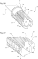
Fig. 1 shows a perspective view of a cap with a keyway shaping element for a lock according to a first embodiment; -
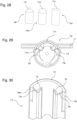
Fig. 2 shows a sectioned rear view of the cap and the keyway shaping element ofFig. 1 mounted in a housing; -
Fig. 3 shows part of the configuration ofFig. 2 in a sectioned side view; -
Fig. 4 shows a perspective view of the lock according to the first embodiment, wherein the housing is not shown; -
Fig. 5 shows a perspective view of a key operable with the lock according to the first embodiment; -
Fig. 6 shows a partially sectioned front view of the configuration ofFig. 4 with the key ofFig. 5 inserted therein; -
Fig. 7 shows a perspective view of the cap and variants of the keyway shaping elements; -
Fig. 8 shows a partially sectioned rear view of a variant shown inFig. 7 in the assembled state; -
Fig. 9 shows a partially sectioned rear view of another variant shown inFig. 7 in the assembled state; -
Fig. 10 shows a partially sectioned rear view of a further variant shown inFig. 7 in the assembled state; -
Fig. 11 shows a perspective view of a variant of the cap with a keyway shaping element; -
Fig. 12 shows a partially sectioned rear view of the cap and the keyway shaping element ofFig. 11 mounted in a housing; -
Fig. 13 shows part of the configuration ofFig. 12 in a sectioned side view; -
Fig. 14 shows a perspective view of a cap with a keyway shaping element for a lock according to a second embodiment; -
Fig. 15 shows the cap with the keyway shaping element ofFig. 14 in the assembled state; -
Fig. 16 shows the configuration ofFig. 15 in a front view; -
Fig. 17 shows a perspective view of a part of a key and of the lock according to the second embodiment; -
Fig. 18 shows part of the plug for the lock ofFig. 17 ; -
Fig. 19 shows variants of the keyway shaping element for the lock according to the second embodiment; -
Fig. 20 shows another variant of the keyway shaping element for the lock according to the second embodiment; -
Fig. 21 shows a perspective view of a part of a key and of the lock according to the second embodiment including the keyway shaping element ofFig. 20 ; -
Fig. 22 shows another variant of the keyway shaping element for the lock according to the second embodiment; -
Fig. 23 shows a perspective view of a part of a key and of the lock according to the second embodiment including the keyway shaping element ofFig. 22 ; -
Fig. 24 shows another variant of the keyway shaping element for the lock according to the second embodiment; -
Fig. 25 shows a front view of the lock according to the second embodiment including the keyway shaping element ofFig. 24 ; -
Fig. 26 shows a perspective view of a part of a key and of a lock according to a third embodiment; -
Fig. 27 shows a detail of the configuration ofFig. 26 , wherein the rearward part is shown in a sectioned view; -
Fig. 28 shows variants of the keyway shaping element for a lock to the third embodiment; -
Fig. 29 shows a rear view of the configuration ofFig. 26 ; -
Fig. 30 shows a detail of the key ofFig. 26 ; -
Fig. 31 shows a perspective view of a part of a variant of the lock according to the third embodiment; and -
Fig. 32 shows a rear view of the configuration ofFig. 31 together with a key inserted therein. - The embodiments of the lock described hereinafter comprise the following components:
- a plug, which includes a keyway configured to receive a key (see e.g. the
plug 20 inFig. 4 ), - a housing with a circular cylindrical opening, in which the plug is accommodated (see e.g. the
housing 50 inFig. 2 ), - at least one keyway shaping element, which is formed separate from the plug.
- The embodiments may comprise:
- one or more blocking bars for preventing a rotation of the plug with respect to the housing when the lock is in the locked state (see the blocking
bar 30 inFig. 4 ), - one or more validating elements configured to cooperate with a key introduced into the keyway to read a key coding (see e.g. the validating
elements 40 inFig. 4 ). - The individual embodiments and variants thereof are now described in more detail.
-
Fig. 1 shows acap 10a, which serves for covering the front end of the plug 20 (seeFig. 4 ). Thecap 10a has a circular cylindrical cross-section and comprises a plate, which is provided at its periphery with anedge element 12a. Thecap 10a includes apassage 13a which is part of the keyway. Theedge element 12a has a clearance for receiving akeyway shaping element 16a. The latter has the form of a curved ribbon and includes a protrudingportion 17a, e.g. in the form of one or more teeth. - At the position of said clearance of the
edge element 12a thecap 10a forms anarcuate segment 14a. The latter includes at least oneslit 15a which runs alongside of thesegment 14a. In the assembled state as shown inFig. 2 , thekeyway shaping element 16a is immovably attached to theplug 20 by means of thecap 10a. The protrudingportion 17a of thekeyway shaping element 16a extends through theslit 15a into the keyway. - The
keyway 21 defined in theplug 20 has a predetermined profile when seen in a plane perpendicular to the direction into which a key is introduced into thekeyway 21. Here, the profile of thekeyway 21 has an arcuatemiddle portion 21a connecting twoside portions return portion portion 17a of thekeyway shaping element 16a redefines said predetermined keyway profile in theplug 20. Here, the protrudingportion 17a includes teeth and thus has the effect that the outer side of themiddle portion 21a of thekeyway 21 is no longer defined by a circular line, but by a serrated curve. - As shown in
Fig. 3 , thecap 10a is at least partially arranged within thehousing 50. Theperipheral face 18a of thekeyway shaping element 16a is adjacent to thehousing 50. The latter includes astep 50a which is adjacent to the rearward side of thekeyway shaping element 16a. -
Fig. 4 shows an example of a lock including thecap 10a, theplug 20, and the validatingelements 40. - The
plug 20 comprises akeyway 21, which extends in the insertion direction of the key and which serves for receiving the shank of the key. - The
plug 20 is provided with an axle 11 (see alsoFig. 6 ) which extends along arotation axis 11a and which is attached to thecap 10a. To this end, thecap 10a may be provided with a peg including a hole for receiving the end of theaxle 11, see thepeg 5a inFig. 7 . - The
plug 20 hasribs 27 andslots 23 therebetween, which are arranged tranversally to therotation axis 11a. The validatingelements 40 are received in theslots 23 and arranged on theaxle 11 in a rotatable manner around therotation axis 11a. Theslots 23 are configured such that a portion of a validatingelement 40 can cooperate with at least one blockingbar 30. - Each validating
element 40 has afirst arm 41, which is configured to contact a coding part of a key, and a second arm with arecess 44. Here, the validatingelements 40 are arranged in an alternating inverted manner so that thefirst arms 41 point alternatingly to the left and right side. - The
plug 20 includes further a receivinggroove 22, which extends alongside of theplug 20 and which serves for receiving the blockingbar 30 in the unlocked state of the lock. - The blocking
bar 30 is preloaded such that in the locked state of the lock it is pushed into a longitudinal groove which is formed in the housing 50 (not shown). Said longitudinal groove extends along a longitudinal direction which is arranged parallel to therotation axis 11a, around which the plug is rotatable with respect to thehousing 50 in the unlocked state of the lock. The pushing force is e.g. produced by elastic means, e.g. in the form of one or more springs 34. - In the example of
Fig. 4 a second receiving groove is formed in theplug 20 opposite to thegroove 22 for receiving a second blocking bar in the unlocked state of the lock. The second blocking bar is preloaded in a similar way as the blockingbar 30 by means of elastic means, so that, in the locked state of the lock, it is pushed into a longitudinal groove formed in thehousing 50. - In the locked state of the lock, the blocking bars are arranged between the
plug 20 and thehousing 50, whereby a rotation of the components including thecap 10a, theplug 20, the blocking bars 30, and the validatingelements 40 with respect to thehousing 50 is disabled. - When a key with the correct coding is used, then the validating
elements 40 and with it therecesses 44 have the correct position, so that the blockingbar 30 can be received in a receiving space formed byrecesses 44 of the validatingelements 40 and the receivinggroove 22 in theplug 20, and in an analogous manner, the second blocking bar can be received in a receiving space formed byrecesses 44 of the validatingelements 40 and the second receiving groove in theplug 20. Thereby, the blocking bars are released out of the longitudinal grooves in thehousing 50 so that the components including thecap 10a, theplug 20, the blocking bars 30, and the validatingelements 40 can be rotated relative to thehousing 50 around therotation axis 11a. -
Fig. 5 shows an example of the key 70a configured to be used with the lock ofFig. 4 . The key 70a has a handlingpart 77, e.g. a bow, and akey shank 71a extending from the handlingpart 77 and insertable into thekeyway 21 of the lock. - In the present embodiment, the
key shank 71a has a semi-closed profile enclosing at least partially the coding part. Thekey shank 71a has an arcuatemiddle portion 72a connecting twoside portions return portion key shank 71a is shaped towards its middle of thekey shank 71a, e.g. U-shaped. Theportions portions key shank 71a and may have e.g. a wavelike course. The coding track may be formed e.g. by a line of successive channel portions and/or ridge portions. - When looking at the key 70a itself, the portions 73-76 prevent that the coding part of the key 70a is visible from outside. This impedes an unauthorized duplication of the key 70a e.g. by producing a copy based on pictures taken from the key 70a.
- The outer face of the
key shank 71a is adapted to the profile defined by thekeyway shaping element 16a. To this end, the outer face ofkey shank 71a is formed complementary to the protrudingportion 17a of thekeyway shaping element 16a. Here, thekey shank 71a includesgrooves 78a for receiving the teeth forming the protrudingportion 17a. - When inserting the key 70a into the lock, the teeth of the protruding
portion 17a engages into thegrooves 78a and thefirst arm 41 of a validatingelement 40 protrudes into the coding cavity 74' or 76' (seeFig. 6 ) and follows the coding track of the key 70a formed therein, whereby a validatingelement 40 is rotated accordingly around theaxis 11a. Once thekey shank 71a is fully inserted, each validatingelement 40 and with it itsrecess 44 have a specific angular position. Said position is such that the blocking bars can enter into therecesses 44 when the key 70a has the correct coding. -
Fig. 1 shows one possible example of the protrudingportion 17a of thekeyway shaping element 16a. A wide variety of shapes are conceivable. Seen in a front view, the protruding portion may include one or more straight portions, one or more curved portions or combinations thereof. -
Fig. 7 shows thekeyway shaping element 16a together with other examples of thekeyway shaping element - As is also apparent from
Fig. 8 , the protrudingportion 17b of thekeyway shaping element 16b has teeth which protrude into thekeyway 21 formed in theplug 20. The number of the teeth and the shape, in particular the height, as well as the position of each tooth may be arbitrarily chosen. - As is also apparent from
Fig. 9 , the protrudingportion 17c of thekeyway shaping element 16c has an arcuate shape. Its form, in particular the length and the curvature, may be arbitrarily chosen. In the example shown inFig. 9 , the parameter D denotes the diameter of the circumcircle which encloses theplug 20, wherein the centre of this circumcircle is on therotation axis 11a. The protrudingportion 17c is defined by a section of a circle with radius R, wherein the centre c of this circle is chosen to be offset to therotation axis 11a. - As is also apparent from
Fig. 10 , the protrudingportion 17d of thekeyway shaping element 16d has a polygonal shape. Its form, in particular the length and the height of a straight section, may be arbitrarily chosen. In the example shown inFig. 10 , the protrudingportion 17d is defined by a number of straight sections of length s, which touch the inscribed circle with diameter d and centre on therotation axis 11a, wherein d < D. The inscribed circle is shown inFig. 10 as a broken line. - In the examples shown in
Fig. 7 , thecap 10a and akeyway shaping element 17a-17d are configured such that the latter can be retained axially in thecap 12a. Other configurations are conceivable.Fig. 11 shows an example, in which thekeyway shaping element 16e is retained radially in thecap 10e. Theedge element 12e has aclearance 15e so that two ends are formed, each having arecess 9e with an undercut shape. The ends of thekeyway shaping element 17e is designed complementary to said shape, see alsoFig. 12 . - Here, the protruding
portion 17e of thekeyway shaping element 16e has a toothed profile. As with the keyway shaping elements ofFig. 7 , the protrudingportion 17e of thekeyway shaping element 16e may be arbitrarily shaped to redefine thepredetermined keyway profile 21a-21e in theplug 20. - The
cap 10e has in the middle a protrudingelement 5e, which defines part of the shape of thekeyway 21 and which is received in arecess 26 formed in theplug 20, seeFig. 13 . In the assemble state, the rearward side of thekeyway shaping element 16e is adjacent to thestep 50a in thehousing 50. - The
keyway shaping elements 16a-16e are e.g. made of metal. Thekeyway shaping element 16a-16d may be manufactured e.g. by metal injection moulding. Thekeyway shaping element 16e may be manufactured by machining a piece of raw material, e.g. by laser cutting. - The shank of a key which is useable with a lock having a
keyway shaping element 16a-16e has an outer surface which is complementary to the protrudingportion 17a-17e. Thus, the shank of the key may have for instance one or more grooves (seegrooves 78a inFig. 5 ) and/or may have an outer surface defined by one or more curved or straight sections or combinations thereof. - The
keyway shaping element 16a-16e cooperate with the outer surface of the key shank. It is possible to configure the keyway shaping element such that it cooperates with the inner surface of the key shank. -
Fig. 14 shows acap 10f with theedge element 12f and akeyway shaping element 16f. - The
cap 10f has thepassage 13a. A protrudingelement 5f defining part of thekeyway 21 and including aslot 6f is formed in the middle of thecap 10f. The protrudingelement 5f has ahole 9f going transversally through theslot 6f for receiving the ends of a pin 7 (seeFig. 15 ). - The
keyway shaping element 16f is formed as a plate. It has a protrudingportion 17f to redefine thekeyway 21 and a through-hole 19f for fixation to thecap 10f. - In the assembled state as shown in
Fig. 15 , thekeyway shaping element 16f is received in theslot 6f and fixed by thepin 7 which goes throughholes Fig. 16 , the protrudingportion 17f protrudes into thepassage 13a of thecap 10f and thus into thekeyway 21. - The
edge element 12f inFig. 14 and 15 is shown with aclearance 15f, so that thecap 10f forms there anarcuate segment 14f. A keyway shaping element similar to thekeyway shaping element 16e may be introduced into theclearance 15f. Thus, different kinds of keyway shaping elements may be arranged in a combined way on thecap 10f. When providing thekeyway shaping element 16f only, theclearance 15f may be omitted, so that theedge element 12f extends fully around the protrudingelement 5f. This configuration is shown inFig. 17 . - Here, the protruding
portion 17f of thekeyway shaping element 16f has teeth. Accordingly, the inner surface of thekey shank 71f hasgrooves 78f for engagement with the teeth, seeFig. 17 . Theplug 20 has arecess 26, in which the protrudingelement 5f can be received, seeFig. 18 . ThisFig. 18 shows also thecentral bore 25 in theplug 20 for receiving theaxle 11. - Similar as with the keyway shaping elements of
Fig. 7 , the protrudingportion 17f of thekeyway shaping element 17f may be arbitrarily shaped to redefine the predetermined keyway profile in theplug 20. - Seen in a front view, the protruding portion may include one or more straight portions, one or more curved portions or combinations thereof.
Fig. 19 shows further examples of akeyway shaping element - The
keyway shaping element 16g has a protrudingportion 17g defined by a curved shape. The latter may be defined e.g. by a section of a circle, wherein the centre of this circle is chosen to be offset to therotation axis 11a, so that the protrudingportion 17g protrudes from below into themiddle portion 21a of thekeyway 21. - The
keyway shaping element 16h has a protrudingportion 17h with a polygonal shape. - In a further embodiment, the keyway shaping element may also be configured such that it can be placed in a
slot 23 of theplug 20 and attached to theaxle 11 to which the validatingelements 40 are attached.Fig. 20 shows an example of thekeyway shaping element 16i, which is formed as a plate. It has a protrudingportion 17i, which may be similar to one of thekeyway shaping element 17f, and an end with ahole 19i for attachment to theaxle 11. -
Fig. 21 shows the assembled state, in which thekeyway shaping element 16i is received in a front slot formed in theplug 20 and attached to the axle 11 (not visible). The attachment is such that thekeyway shaping element 16i is immovably attached to theplug 20 by means of theaxle 11. Thecap 10i may be configured such that it has a protruding element similar as the protrudingelement 5e of the keyway shaping 10e. The key 71f with thegrooves 78f ofFig. 17 may be used to engage with the teeth of thekeyway shaping element 16i. - In
Fig. 21 thekeyway shaping element 16i is positioned in theforemost slot 23 of theplug 20. It is conceivable that thekeyway shaping element 16i is received in anotherslot 23 of theplug 20 and attached there to theaxle 11, so that it is positioned within the axial length of theplug 20. - The length of a
groove 78f in thekey shank 71f can be chosen in dependency on the position of thekeyway shaping element 16i along theplug 20. Thereby, a master and slave lock system may be provided. For instance, a first lock with akeyway shaping element 16i in the foremost slot 23 (in the following "first position") and a second lock with akeyway shaping element 16i within the axial length of the plug 20 (in the following "second position") may be provided. A key with grooves sufficiently long so that they extend at least from the first to the second position can open the first and second lock, whereas a key with shorter grooves can open only the second look, but not the first one, since the end of those shorter grooves will abut against thekeyway shaping element 16i in the first position, so that the key shank cannot fully be inserted into the keyway. - The keyway shaping element may also be configured such that it redefines another portion of the
keyway 21 than itsmiddle portion 21a. -
Fig. 22 shows an example of thekeyway shaping element 16j, which is formed as a plate having protrudingportions 17j at both sides. It has further ahole 19f similar as thekeyway shaping element 16f so that it can be fixed by a pin in theslot 6f ofcap 10f. - The shape of the
upper part 18j of thekeyway shaping element 16j corresponds to the lower part of themiddle portion 21a of thekeyway 21, so that thispart 18j does not protrude into themiddle portion 21a, seeFig. 23 . - The
keyway shaping element 16j has on each side a protrudingportion 17j protruding into thereturn portions keyway 21. Here, the protrudingportions 17j are formed as one or more teeth. A key useable with thekeyway shaping element 16j has akey shank 71j, in which the outer surface of thereturn portions portions 17j. Here, thereturn portions grooves 78j for engagement with the teeth of the protrudingportions 17j. - Other keyway shaping elements are conceivable to redefine other portions of the
keyway 21.Fig. 24 shows an example, in which the upper part and the sides of thekeyway shaping element 16k have protrudingportions portion 17f corresponds to that ofkeyway shaping element 16f and the protrudingportions 17j correspond to those ofkeyway shaping element 16j. In the assembled state as shown inFig. 25 , thekeyway shaping element 16j is placed in theslot 6f ofcap 10f and attached to theplug 20, so that the protrudingportion 17f redefines themiddle portion 21a of thekeyway 21, and the protrudingportions 17j redefine thereturn portions keyway 21. - Instead of providing one single
keyway shaping element 16k it is also possible to use more than one keyway shaping element. For instance, one may combinekeyway shaping elements cap 10f to theplug 20, which result in the same redefinition of the keyway as thekeyway shaping element 16k. The thickness of the keyway shaping elements and the thickness of theslot 6f ofcap 10f are adapted to each other such that more than one keyway shaping element can be placed in theslot 6f. - In the first and second embodiments, keyway shaping elements are provided at the front end of the
keyway 21. It is conceivable to provide one or more keyway shaping elements within the axial length of thekeyway 21. -
Fig. 26 shows an example, in which theplug 20 is provided withkeyway shaping elements plug 22. Here, theplug 20 is covered by acap 10, which is free of a keyway shaping element and which has thepassage 13a. - The
plug 20 hasside wings 21b', 21d'.Side wing 21b' defines theside portion 21b of thekeyway 21 andside wing 21d' defines theside portion 21d of thekeyway 21. Akeyway shaping element blind hole 24 formed in aside wing 21b', 21d', see alsoFig. 27 . - A
keyway shaping element 16l, 16m is a formed by a pin, which is fixed in ablind hole 24 e.g. by press-fitting. The fixation is such that akeyway shaping element plug 20 when the key shank 71l of a key is inserted into theplug 20. In the assembled state, the front end of akeyway shaping element portion 17l, 17m which protrudes into thekeyway 21 and thereby redefines its geometry. - The length of a
keyway shaping element plug 20 and the shape of the protruding portion may vary.Fig. 28 shows examples, in which the keyway shaping element 16l has a conical protruding portion 17l, thekeyway shaping element 16m has a spherical protrudingportion 17m, and thekeyway shaping element 16n has a circular cylindrical protrudingportion 17n - A key 70l, which is useable with a lock of
Fig. 26 , has a key shank 71l including at least onegroove 78l, 78m for engagement with the at least onekeyway shaping element 17l, 17m. In the example shown inFig. 29 and 30 the key shank 71l of the key 70l hasgrooves 78l, 78m which are formed on the side portions 73l, 75l of the key shank 71l. The cross-section of thegroove 78l, 78m corresponds to the shape, which the correspondingkeyway shaping element 17l, 17m has when seen in a side view. Here, the groove 78l has a triangular cross-section for engagement with the conical keyway shaping element 17l and thegroove 78m has a circular cross-section for engagement with the sphericalkeyway shaping element 17m. - A groove configured to cooperate with the
keyway shaping element 17n ofFig. 28 would have a rectangular cross-section. - The length of a
groove 78l, 78m is adapted to the position of akeyway shaping element 17l, 17m along theplug 20. When the key shank 71l is fully inserted into thekeyway 21, akeyway shaping element 17l, 17m will be positioned at the closed end of thegroove 78l, 78m. - Alternatively or in addition to the provision of one or
more grooves 78l, 78m it is also conceivable to change the profile geometry of the key shank. Theplug 20 ofFig. 31 hasside wings 21b' and 21d', which enclose an angle of A0, seeFig. 32 . - Both
side wings 21b', 21d' are provided with keyway shaping elements 16o. A keyway shaping element 16o has a protruding portion 17o and may e.g. have the shape of thekeyway shaping element 16m. - The keyway shaping elements 16o protrude into the
keyway 21, so that aside wing 21b', 21d' and the top of a protruding portion 17o enclose an angle of A1, seeFig. 32 . Accordingly, the angle B between the top of a keyway shaping element 17o onwing 21b' and the top of a keyway shaping element 17o onwing 21d' is reduced twice by the angle A1 with respect to the angle A0: B = A0 - 2•A1. - In accordance with the provision of the angle B between the keyway shaping elements 17o, a key useable with a
plug 20 ofFig. 31 has a key shank 71o with side portions 73o, 75o, which are inclined to each other by the reduced angle of B. - Other embodiments are conceivable which change the profile geometry of the key shank. In the example of
Fig. 32 , the plug may e.g. provided with keyway shaping elements 17o on only onewing 21b' or 21d', so that the reduced angle is given by A0 - A1. In another example, the size with which the protruding portions of the keyway shaping elements 17o extend into thekeyway 21 may be different onwings 21b' and 21d'. Accordingly, the angle A1 shown inFig. 32 may be different on both sides, e.g. the angle may correspond to A1 on the left-hand side and to A1' on the right-hand side. In this case the reduced angle is given by A0 - A1 - A1'. - The embodiments described herein allow the provision of a master and slave lock system. For instance a lock according to
Fig. 4 may be a master lock, which can be operated by the key ofFig. 5 . A lock which is configured the same as the one ofFig. 4 , but without thekeyway shaping element 16a may be considered as a slave lock, which can also be operated by the key ofFig. 5 . However, a key having a key shank as the key ofFig. 5 , but without the grooves can operate only the slave lock, but not the master lock, as due to the missing grooves the key shank cannot be inserted in the keyway of the master lock. - The embodiment as shown in
Fig. 32 may define a master lock and the lock ofFig. 32 without the keyway shaping elements 17o may define a slave lock. The key 71o ofFig. 32 , which has side portions 73o, 75o inclined to each other by the angle B, may be used to operate said master and said slave lock, whereas a key having side portions inclined to each other by the angle A may be used to operate the slave lock only, but not the master lock. - From the preceding description, numerous modifications are accessible to one skilled in the art without departing from the scope of protection of the invention that is defined by the claims.
- The keys described here have an arcuate middle portion, on both sides of which a U-shaped wall portion is attached. Other profiles are conceivable, in particular those as shown in
Fig. 11 to 46c ofUS 9,920,548 B2 Fig. 14 to 17 ofWO 2016/162363 A1 and inFig. 13 ofWO 2018/041277 A1 of the same applicant. In general, the key shank may at least in a part of its axial length include a profile which is closed or semi-closed to define at least one cavity including a key coding. - The key shank with the key coding may be manufactured in one piece. The at least one cavity is formed such that the key coding is at least in part invisible from outside. The profile may have a shape which is different from a U-shape.
Claims (16)
- A lock configured to be operated by a key (70a, 70l), the key comprising a key shank (71a, 71f, 71j, 71l, 71o), which at least in a part of its axial length includes a profile which is closed or semi-closed to define at least one cavity (74', 75') including a key coding,
the lock comprises:a plug (20) for receiving the key shank and being configured to be accommodated in a housing (50), the plug being rotatable with respect to the housing in the unlocked state of the lock, the plug including a keyway (21), which is defined by a predetermined geometry and has a transverse keyway profile including an arcuate portion (21a),and at least one keyway shaping element (16a-16j, 16l-16o), which is formed separate from the plug and is fixed to the plug such that it is immovable relative to the plug when the key shank is inserted into the plug, a protruding portion (17a-17j, 17l-17n) of the at least one keyway shaping element protrudes into the keyway to redefine its geometry. - The lock according to claim 1, wherein the protruding portion (17a-17n) of the at least one keyway shaping element (16a-16o) extends in an axial direction of the keyway (21) less than an axial extent of the keyway, preferably the axial extent of the protruding portion is less than the extent of the protruding portion transversally to the axial direction.
- The lock according to any one of the preceding claims, wherein the at least one keyway shaping element (16a-16o) is arranged at the forward end of the plug (20) or within the axial length of the plug.
- The lock according to any one of the preceding claims, which comprises further at least one of the following features A1 to A3:A1) a cap (10a, 10e, 10f) configured to cover the front end of the plug (20), the at least one keyway shaping element (16a-16h, 16j-16k) being attached to the cap,A2) an axle (11) which is fixed to the plug (20), the at least one keyway shaping element (16i) having a hole (19i) for attachment to the axle,A3) a blind hole (24) formed in the plug (20), a part of the at least one keyway shaping element (16l-16o) being received in the blind hole.
- The lock according to any one of the preceding claims, wherein said protruding portion (17l-17n) of the at least one keyway shaping element (16l-16o) has at least in part one of the following shapes:- a shape including one or more teeth,- a polygonal shape,- a shape curved in one or more directions,- a conical shape,- a spherical shape,- a circular cylindrical shape.
- The lock according to any one of the preceding claims, wherein the at least one keyway shaping element (16l-16o) is formed by a bent ribbon, by a plate having an edge, which defines said protruding portion, or by a pin.
- The lock according to any one of the preceding claims, wherein the keyway includes at least one side portion (21b, 21d) adjacent to the arcuate portion, preferably the keyway includes at least one return portion (21c, 21e) adjacent to the at least one side portion.
- The lock according to claim 7, wherein said protruding portion (17a-17j, 17l-17n) of the at least one keyway shaping element (16a-16j, 16l-16o) protrudes into the arcuate portion (21a), the at least one side portion (21b, 21d) and/or the at least one return portion (21c, 21e) of the keyway profile.
- The lock according to any one of the preceding claims, which comprises at least two keyway shaping elements (16a-16j, 16l-16o), each being formed separate from the plug (20) and fixed to the plug such that they are immovable relative to the plug when the key shank is inserted into the plug, the protruding portions (17a-17j, 17l-17n) of said at least two keyway shaping elements protrude into the keyway (21) to redefine its geometry at different locations, preferably said at least two keyway shaping elements being arranged at the same axial position along the axial direction of the keyway or being arranged offset to each other along the axial direction of the keyway.
- The lock according to any one of the preceding claims, which comprises further at least one of the following features B1 to B3:B1) at least one validating element (40) configured to cooperate with the key (70a, 70l) introduced into the plug (20) to read the key coding, preferably the at least one validating element is movably arranged in a plane transversally to the rotation axis (11a) around which the plug (20) is rotatable when the lock is in the unlocked state, most preferably the at least one validating element (40) is rotatable around the rotation axis,B2) at least one blocking bar (30), which, in the locked state of the lock, engages into a longitudinal groove formed in the housing (50) and which, in the unlocked state of the lock, is receivable in a receiving space in the plug (20),B3) a housing (50) to accommodate the plug (20) such that the plug (20) is rotatable relative thereto, preferably the housing defining a portion of the geometry of the keyway (21), most preferably said portion being defined by a curved wall portion of the housing.
- A lock system comprising at least one lock according to any one of the preceding claims and at least one key (70a, 70l) to operate said at least one lock.
- The lock system according to claim 11, wherein the key shank (71a, 71f, 71j, 71l, 71o) of the at least one key (70a, 70l) includes a wall portion, which, seen in a plane transverse to the longitudinal direction in which the key shank extends, has a shape complementary to the protruding portion (17a-17j, 17l-17n) of the at least one keyway shaping element (16a-16o).
- The lock system according to claim 11 or 12, wherein the key shank (71a, 71f, 71j, 71l) of the at least one key (70a, 70l) includes at least one groove (78a, 78f, 78j, 78l, 78m) to cooperate with the protruding portion (17a, 17b, 17e, 17f, 17i, 17j, 17l-17n) of the at least one keyway shaping element (16a, 16b, 16e, 16f, 16i-16n).
- The lock system according to any one of claims 11 to 13, wherein the profile of the key shank (71a, 71f, 71j, 71l, 71o) defining the at least one cavity (74', 75') includes an arcuate wall portion (72, 72a), preferably the profile includes at least one side wall portion (73, 73l, 73o, 75, 75l, 75o) connected to the arcuate wall portion, most preferably the profile includes at least one return wall portion (74, 74j, 76, 76j) connected to the at least one side wall portion.
- The lock system according to any of claims 11 to 14, further comprising at least a second lock, which is configured to be operated by said at least one key (70a, 70l), said at least second lock corresponds to the at least one lock without the at least one keyway shaping element (16a-16o) .
- A method for manufacturing a lock according to any one of claims 1 to 10, including the steps of- providing a plug (20), which includes a keyway (22) being defined by a predetermined geometry, and- attaching at least one keyway shaping element (16a-16j, 16l-16o) to the plug so that a portion of the at least one keyway shaping element protrudes into the keyway to redefine its geometry, the attachment of the at least one keyway shaping element to the plug being such that it is immovable relative to the plug when the key shank is inserted into the plug.
Applications Claiming Priority (2)
| Application Number | Priority Date | Filing Date | Title |
|---|---|---|---|
| EP19175228 | 2019-05-17 | ||
| PCT/EP2020/063217 WO2020234054A1 (en) | 2019-05-17 | 2020-05-12 | A lock configured to be operated by a key |
Publications (2)
| Publication Number | Publication Date |
|---|---|
| EP3969697A1 EP3969697A1 (en) | 2022-03-23 |
| EP3969697B1 true EP3969697B1 (en) | 2023-12-06 |
Family
ID=66625009
Family Applications (1)
| Application Number | Title | Priority Date | Filing Date |
|---|---|---|---|
| EP20724147.2A Active EP3969697B1 (en) | 2019-05-17 | 2020-05-12 | A lock configured to be operated by a key |
Country Status (3)
| Country | Link |
|---|---|
| US (1) | US20220396971A1 (en) |
| EP (1) | EP3969697B1 (en) |
| WO (1) | WO2020234054A1 (en) |
Families Citing this family (2)
| Publication number | Priority date | Publication date | Assignee | Title |
|---|---|---|---|---|
| WO2024220743A1 (en) * | 2023-04-21 | 2024-10-24 | Brooks Todd D | Mechanically keyed locks with isolated validation |
| WO2026085527A2 (en) * | 2024-10-18 | 2026-04-23 | Brooks Todd D | Mechanically keyed locks with isolated validation |
Family Cites Families (28)
| Publication number | Priority date | Publication date | Assignee | Title |
|---|---|---|---|---|
| US494340A (en) * | 1893-03-28 | meinke | ||
| US587603A (en) * | 1897-08-03 | Giuseppe picciont | ||
| US3754422A (en) * | 1972-06-26 | 1973-08-28 | American Locker Co | Cylinder lock and u-shaped key and method of forming same |
| US4083212A (en) * | 1977-05-16 | 1978-04-11 | Sargent & Greenleaf, Inc. | Rotary disc tumbler cylinder lock |
| FI780542A7 (en) * | 1978-02-17 | 1979-08-18 | Waertsilae Oy Ab | SLIDING CYLINDER LABORATORY |
| FI74320C (en) * | 1979-09-07 | 1988-01-11 | Waertsilae Oy Ab | Cylinder lock. |
| US4359886A (en) * | 1981-02-25 | 1982-11-23 | Sargent & Greenleaf, Inc. | Key lock cylinder for possibly contaminated environments |
| AU553441B2 (en) * | 1981-03-30 | 1986-07-17 | Australian Lock Company Pty Ltd | Cylinder lock |
| US5131247A (en) * | 1990-05-08 | 1992-07-21 | Hsu Yun Tung | Lock assembly with curved keyway |
| US5687594A (en) * | 1996-01-18 | 1997-11-18 | Wang; Teng-Kuo | Lock and key combination with changeable combination of locking pieces |
| US5934121A (en) * | 1997-12-17 | 1999-08-10 | Chen; Waterson | Lock apparatus |
| DE19844593C1 (en) * | 1998-09-29 | 2000-03-02 | Huf Huelsbeck & Fuerst Gmbh | Lock cylinder for motor vehicle has core with radial cut out for spring engaging lock cylinder |
| US6481255B2 (en) * | 1999-09-01 | 2002-11-19 | International Security Products, Inc. | High security side bar lock |
| DE19944070C2 (en) * | 1999-09-15 | 2001-08-16 | Huf Huelsbeck & Fuerst Gmbh | Locking device, in particular for motor vehicles |
| AT411779B (en) * | 2002-03-29 | 2004-05-25 | Evva Werke | KEY FOR CYLINDER LOCKS AND CYLINDLE LOCKS |
| US6925844B2 (en) * | 2003-01-30 | 2005-08-09 | Chien-Kuo Liu | Lock having a helical keyway and accompanying key and methods therefor |
| US7353675B1 (en) * | 2006-09-18 | 2008-04-08 | Sheng-Ho Chao | Lock barrel and a driving part for the same |
| CA2618178C (en) * | 2007-02-02 | 2014-05-20 | Kaba Ilco Corp. | Key blank with projection |
| DE102007007688A1 (en) * | 2007-02-16 | 2008-08-21 | C. Ed. Schulte Gmbh Zylinderschlossfabrik | Lock cylinder with wear protection |
| WO2011063968A1 (en) * | 2009-11-28 | 2011-06-03 | Volkswagen Aktiengesellschaft | Locking system |
| AP4021A (en) * | 2012-02-16 | 2017-02-01 | Abloy Oy | Key and disc tumbler cylinder lock |
| DE102012103925A1 (en) * | 2012-05-04 | 2013-11-07 | Witte Automotive Gmbh | Lock cylinder e.g. steering wheel lock cylinder for motor car, has locking projection that is held before the locking unit, if key is not inserted into key channel so that cylinder core is not rotated |
| AU2014334478B2 (en) * | 2013-10-11 | 2018-04-05 | Urbanalps Ag | Key and lock |
| AU2013248267B1 (en) * | 2013-10-28 | 2014-06-26 | Camware Holdings Pty Ltd | Lock system |
| WO2016162363A1 (en) | 2015-04-09 | 2016-10-13 | Urbanalps Ag | Lock and key |
| AU2017318104A1 (en) | 2016-09-01 | 2019-02-28 | Urbanalps Ag | A key for controlling a lock with a cylindrical plug and a lock for validating this key |
| AU2020281028A1 (en) * | 2019-12-23 | 2021-07-08 | Assa Abloy Australia Pty Limited | A tumbler lock assembly |
| DE102020117226A1 (en) * | 2020-06-30 | 2021-12-30 | ABUS August Bremicker Söhne Kommanditgesellschaft | Lock cylinder, locking device, locking system, key and key blank |
-
2020
- 2020-05-12 WO PCT/EP2020/063217 patent/WO2020234054A1/en not_active Ceased
- 2020-05-12 US US17/609,025 patent/US20220396971A1/en not_active Abandoned
- 2020-05-12 EP EP20724147.2A patent/EP3969697B1/en active Active
Also Published As
| Publication number | Publication date |
|---|---|
| US20220396971A1 (en) | 2022-12-15 |
| WO2020234054A1 (en) | 2020-11-26 |
| EP3969697A1 (en) | 2022-03-23 |
Similar Documents
| Publication | Publication Date | Title |
|---|---|---|
| EP2406444B1 (en) | Cylinder lock and key combination | |
| EP1236849B2 (en) | Key for a cylinder lock | |
| CA2743603C (en) | Profiled key for cylinder locks | |
| EP0395632B1 (en) | Cylinder lock and locking tumbler | |
| EP2902569B1 (en) | Disc tumbler cylinder lock | |
| EP3969697A1 (en) | A lock configured to be operated by a key | |
| HK1003483B (en) | Cylinder lock and locking tumber | |
| CN101772610B (en) | Key for operating a lock with enhanced impact resistance | |
| EP1772576B1 (en) | Cylinder lock system and set of keys | |
| NO318266B1 (en) | Combination of cylinder load and key, as well as key, key blank and load. | |
| EP4577710B1 (en) | A key plug, a cylinder lock, a cylinder lock and key combination and a method to manufacture a key plug | |
| JP2019526725A (en) | Key that controls a lock with a cylindrical plug, and a lock that authenticates this key | |
| EP2423412A2 (en) | Lock and key blade | |
| TWI650472B (en) | Cylinder lock | |
| RU2018124652A (en) | SECRET LOCK | |
| EP2894279A1 (en) | Security device for lock cylinders | |
| PL66361Y1 (en) | Cylinder lock with flat key | |
| EP1366256B1 (en) | Rotating pin tumbler side bar lock with side bar control | |
| EP3736399A1 (en) | Reprogrammable lock | |
| JP3654848B2 (en) | Cylinder lock | |
| WO2020229230A1 (en) | Lock with at least one blocking bar | |
| JP6377896B2 (en) | Key for pin tumbler lock and pin cylinder lock | |
| EP3371394B1 (en) | A set of profile members in combination with a key plug, a method to manufacture such a key plug and a combination also including an associated key | |
| CN2479156Y (en) | multifunction lock | |
| JP3866240B2 (en) | Unlocking tool, unlocking tool set, and unlocking method of cylinder lock |
Legal Events
| Date | Code | Title | Description |
|---|---|---|---|
| STAA | Information on the status of an ep patent application or granted ep patent |
Free format text: STATUS: UNKNOWN |
|
| STAA | Information on the status of an ep patent application or granted ep patent |
Free format text: STATUS: THE INTERNATIONAL PUBLICATION HAS BEEN MADE |
|
| PUAI | Public reference made under article 153(3) epc to a published international application that has entered the european phase |
Free format text: ORIGINAL CODE: 0009012 |
|
| STAA | Information on the status of an ep patent application or granted ep patent |
Free format text: STATUS: REQUEST FOR EXAMINATION WAS MADE |
|
| 17P | Request for examination filed |
Effective date: 20211105 |
|
| AK | Designated contracting states |
Kind code of ref document: A1 Designated state(s): AL AT BE BG CH CY CZ DE DK EE ES FI FR GB GR HR HU IE IS IT LI LT LU LV MC MK MT NL NO PL PT RO RS SE SI SK SM TR |
|
| DAV | Request for validation of the european patent (deleted) | ||
| DAX | Request for extension of the european patent (deleted) | ||
| GRAP | Despatch of communication of intention to grant a patent |
Free format text: ORIGINAL CODE: EPIDOSNIGR1 |
|
| STAA | Information on the status of an ep patent application or granted ep patent |
Free format text: STATUS: GRANT OF PATENT IS INTENDED |
|
| INTG | Intention to grant announced |
Effective date: 20230512 |
|
| GRAS | Grant fee paid |
Free format text: ORIGINAL CODE: EPIDOSNIGR3 |
|
| GRAA | (expected) grant |
Free format text: ORIGINAL CODE: 0009210 |
|
| STAA | Information on the status of an ep patent application or granted ep patent |
Free format text: STATUS: THE PATENT HAS BEEN GRANTED |
|
| RAP1 | Party data changed (applicant data changed or rights of an application transferred) |
Owner name: BANHAM PATENT LOCKS HOLDINGS LIMITED |
|
| AK | Designated contracting states |
Kind code of ref document: B1 Designated state(s): AL AT BE BG CH CY CZ DE DK EE ES FI FR GB GR HR HU IE IS IT LI LT LU LV MC MK MT NL NO PL PT RO RS SE SI SK SM TR |
|
| REG | Reference to a national code |
Ref country code: GB Ref legal event code: FG4D |
|
| P01 | Opt-out of the competence of the unified patent court (upc) registered |
Effective date: 20231102 |
|
| REG | Reference to a national code |
Ref country code: CH Ref legal event code: EP |
|
| REG | Reference to a national code |
Ref country code: DE Ref legal event code: R096 Ref document number: 602020022290 Country of ref document: DE |
|
| REG | Reference to a national code |
Ref country code: IE Ref legal event code: FG4D |
|
| REG | Reference to a national code |
Ref country code: LT Ref legal event code: MG9D |
|
| PG25 | Lapsed in a contracting state [announced via postgrant information from national office to epo] |
Ref country code: GR Free format text: LAPSE BECAUSE OF FAILURE TO SUBMIT A TRANSLATION OF THE DESCRIPTION OR TO PAY THE FEE WITHIN THE PRESCRIBED TIME-LIMIT Effective date: 20240307 |
|
| REG | Reference to a national code |
Ref country code: NL Ref legal event code: MP Effective date: 20231206 |
|
| PG25 | Lapsed in a contracting state [announced via postgrant information from national office to epo] |
Ref country code: LT Free format text: LAPSE BECAUSE OF FAILURE TO SUBMIT A TRANSLATION OF THE DESCRIPTION OR TO PAY THE FEE WITHIN THE PRESCRIBED TIME-LIMIT Effective date: 20231206 |
|
| PG25 | Lapsed in a contracting state [announced via postgrant information from national office to epo] |
Ref country code: ES Free format text: LAPSE BECAUSE OF FAILURE TO SUBMIT A TRANSLATION OF THE DESCRIPTION OR TO PAY THE FEE WITHIN THE PRESCRIBED TIME-LIMIT Effective date: 20231206 |
|
| PG25 | Lapsed in a contracting state [announced via postgrant information from national office to epo] |
Ref country code: LT Free format text: LAPSE BECAUSE OF FAILURE TO SUBMIT A TRANSLATION OF THE DESCRIPTION OR TO PAY THE FEE WITHIN THE PRESCRIBED TIME-LIMIT Effective date: 20231206 Ref country code: GR Free format text: LAPSE BECAUSE OF FAILURE TO SUBMIT A TRANSLATION OF THE DESCRIPTION OR TO PAY THE FEE WITHIN THE PRESCRIBED TIME-LIMIT Effective date: 20240307 Ref country code: ES Free format text: LAPSE BECAUSE OF FAILURE TO SUBMIT A TRANSLATION OF THE DESCRIPTION OR TO PAY THE FEE WITHIN THE PRESCRIBED TIME-LIMIT Effective date: 20231206 Ref country code: BG Free format text: LAPSE BECAUSE OF FAILURE TO SUBMIT A TRANSLATION OF THE DESCRIPTION OR TO PAY THE FEE WITHIN THE PRESCRIBED TIME-LIMIT Effective date: 20240306 |
|
| REG | Reference to a national code |
Ref country code: AT Ref legal event code: MK05 Ref document number: 1638556 Country of ref document: AT Kind code of ref document: T Effective date: 20231206 |
|
| PG25 | Lapsed in a contracting state [announced via postgrant information from national office to epo] |
Ref country code: NL Free format text: LAPSE BECAUSE OF FAILURE TO SUBMIT A TRANSLATION OF THE DESCRIPTION OR TO PAY THE FEE WITHIN THE PRESCRIBED TIME-LIMIT Effective date: 20231206 |
|
| PG25 | Lapsed in a contracting state [announced via postgrant information from national office to epo] |
Ref country code: SE Free format text: LAPSE BECAUSE OF FAILURE TO SUBMIT A TRANSLATION OF THE DESCRIPTION OR TO PAY THE FEE WITHIN THE PRESCRIBED TIME-LIMIT Effective date: 20231206 Ref country code: RS Free format text: LAPSE BECAUSE OF FAILURE TO SUBMIT A TRANSLATION OF THE DESCRIPTION OR TO PAY THE FEE WITHIN THE PRESCRIBED TIME-LIMIT Effective date: 20231206 Ref country code: NO Free format text: LAPSE BECAUSE OF FAILURE TO SUBMIT A TRANSLATION OF THE DESCRIPTION OR TO PAY THE FEE WITHIN THE PRESCRIBED TIME-LIMIT Effective date: 20240306 Ref country code: NL Free format text: LAPSE BECAUSE OF FAILURE TO SUBMIT A TRANSLATION OF THE DESCRIPTION OR TO PAY THE FEE WITHIN THE PRESCRIBED TIME-LIMIT Effective date: 20231206 Ref country code: LV Free format text: LAPSE BECAUSE OF FAILURE TO SUBMIT A TRANSLATION OF THE DESCRIPTION OR TO PAY THE FEE WITHIN THE PRESCRIBED TIME-LIMIT Effective date: 20231206 Ref country code: HR Free format text: LAPSE BECAUSE OF FAILURE TO SUBMIT A TRANSLATION OF THE DESCRIPTION OR TO PAY THE FEE WITHIN THE PRESCRIBED TIME-LIMIT Effective date: 20231206 |
|
| PG25 | Lapsed in a contracting state [announced via postgrant information from national office to epo] |
Ref country code: IS Free format text: LAPSE BECAUSE OF FAILURE TO SUBMIT A TRANSLATION OF THE DESCRIPTION OR TO PAY THE FEE WITHIN THE PRESCRIBED TIME-LIMIT Effective date: 20240406 |
|
| PG25 | Lapsed in a contracting state [announced via postgrant information from national office to epo] |
Ref country code: AT Free format text: LAPSE BECAUSE OF FAILURE TO SUBMIT A TRANSLATION OF THE DESCRIPTION OR TO PAY THE FEE WITHIN THE PRESCRIBED TIME-LIMIT Effective date: 20231206 Ref country code: CZ Free format text: LAPSE BECAUSE OF FAILURE TO SUBMIT A TRANSLATION OF THE DESCRIPTION OR TO PAY THE FEE WITHIN THE PRESCRIBED TIME-LIMIT Effective date: 20231206 |
|
| PG25 | Lapsed in a contracting state [announced via postgrant information from national office to epo] |
Ref country code: SK Free format text: LAPSE BECAUSE OF FAILURE TO SUBMIT A TRANSLATION OF THE DESCRIPTION OR TO PAY THE FEE WITHIN THE PRESCRIBED TIME-LIMIT Effective date: 20231206 |
|
| PG25 | Lapsed in a contracting state [announced via postgrant information from national office to epo] |
Ref country code: SM Free format text: LAPSE BECAUSE OF FAILURE TO SUBMIT A TRANSLATION OF THE DESCRIPTION OR TO PAY THE FEE WITHIN THE PRESCRIBED TIME-LIMIT Effective date: 20231206 Ref country code: SK Free format text: LAPSE BECAUSE OF FAILURE TO SUBMIT A TRANSLATION OF THE DESCRIPTION OR TO PAY THE FEE WITHIN THE PRESCRIBED TIME-LIMIT Effective date: 20231206 Ref country code: RO Free format text: LAPSE BECAUSE OF FAILURE TO SUBMIT A TRANSLATION OF THE DESCRIPTION OR TO PAY THE FEE WITHIN THE PRESCRIBED TIME-LIMIT Effective date: 20231206 Ref country code: IT Free format text: LAPSE BECAUSE OF FAILURE TO SUBMIT A TRANSLATION OF THE DESCRIPTION OR TO PAY THE FEE WITHIN THE PRESCRIBED TIME-LIMIT Effective date: 20231206 Ref country code: IS Free format text: LAPSE BECAUSE OF FAILURE TO SUBMIT A TRANSLATION OF THE DESCRIPTION OR TO PAY THE FEE WITHIN THE PRESCRIBED TIME-LIMIT Effective date: 20240406 Ref country code: EE Free format text: LAPSE BECAUSE OF FAILURE TO SUBMIT A TRANSLATION OF THE DESCRIPTION OR TO PAY THE FEE WITHIN THE PRESCRIBED TIME-LIMIT Effective date: 20231206 Ref country code: CZ Free format text: LAPSE BECAUSE OF FAILURE TO SUBMIT A TRANSLATION OF THE DESCRIPTION OR TO PAY THE FEE WITHIN THE PRESCRIBED TIME-LIMIT Effective date: 20231206 Ref country code: AT Free format text: LAPSE BECAUSE OF FAILURE TO SUBMIT A TRANSLATION OF THE DESCRIPTION OR TO PAY THE FEE WITHIN THE PRESCRIBED TIME-LIMIT Effective date: 20231206 |
|
| PG25 | Lapsed in a contracting state [announced via postgrant information from national office to epo] |
Ref country code: PL Free format text: LAPSE BECAUSE OF FAILURE TO SUBMIT A TRANSLATION OF THE DESCRIPTION OR TO PAY THE FEE WITHIN THE PRESCRIBED TIME-LIMIT Effective date: 20231206 Ref country code: PT Free format text: LAPSE BECAUSE OF FAILURE TO SUBMIT A TRANSLATION OF THE DESCRIPTION OR TO PAY THE FEE WITHIN THE PRESCRIBED TIME-LIMIT Effective date: 20240408 |
|
| PG25 | Lapsed in a contracting state [announced via postgrant information from national office to epo] |
Ref country code: PT Free format text: LAPSE BECAUSE OF FAILURE TO SUBMIT A TRANSLATION OF THE DESCRIPTION OR TO PAY THE FEE WITHIN THE PRESCRIBED TIME-LIMIT Effective date: 20240408 Ref country code: PL Free format text: LAPSE BECAUSE OF FAILURE TO SUBMIT A TRANSLATION OF THE DESCRIPTION OR TO PAY THE FEE WITHIN THE PRESCRIBED TIME-LIMIT Effective date: 20231206 |
|
| REG | Reference to a national code |
Ref country code: DE Ref legal event code: R097 Ref document number: 602020022290 Country of ref document: DE |
|
| PG25 | Lapsed in a contracting state [announced via postgrant information from national office to epo] |
Ref country code: DK Free format text: LAPSE BECAUSE OF FAILURE TO SUBMIT A TRANSLATION OF THE DESCRIPTION OR TO PAY THE FEE WITHIN THE PRESCRIBED TIME-LIMIT Effective date: 20231206 |
|
| PLBE | No opposition filed within time limit |
Free format text: ORIGINAL CODE: 0009261 |
|
| STAA | Information on the status of an ep patent application or granted ep patent |
Free format text: STATUS: NO OPPOSITION FILED WITHIN TIME LIMIT |
|
| PG25 | Lapsed in a contracting state [announced via postgrant information from national office to epo] |
Ref country code: SI Free format text: LAPSE BECAUSE OF FAILURE TO SUBMIT A TRANSLATION OF THE DESCRIPTION OR TO PAY THE FEE WITHIN THE PRESCRIBED TIME-LIMIT Effective date: 20231206 |
|
| PG25 | Lapsed in a contracting state [announced via postgrant information from national office to epo] |
Ref country code: SI Free format text: LAPSE BECAUSE OF FAILURE TO SUBMIT A TRANSLATION OF THE DESCRIPTION OR TO PAY THE FEE WITHIN THE PRESCRIBED TIME-LIMIT Effective date: 20231206 Ref country code: DK Free format text: LAPSE BECAUSE OF FAILURE TO SUBMIT A TRANSLATION OF THE DESCRIPTION OR TO PAY THE FEE WITHIN THE PRESCRIBED TIME-LIMIT Effective date: 20231206 |
|
| 26N | No opposition filed |
Effective date: 20240909 |
|
| REG | Reference to a national code |
Ref country code: DE Ref legal event code: R119 Ref document number: 602020022290 Country of ref document: DE |
|
| REG | Reference to a national code |
Ref country code: CH Ref legal event code: PL |
|
| PG25 | Lapsed in a contracting state [announced via postgrant information from national office to epo] |
Ref country code: MC Free format text: LAPSE BECAUSE OF FAILURE TO SUBMIT A TRANSLATION OF THE DESCRIPTION OR TO PAY THE FEE WITHIN THE PRESCRIBED TIME-LIMIT Effective date: 20231206 |
|
| PG25 | Lapsed in a contracting state [announced via postgrant information from national office to epo] |
Ref country code: LU Free format text: LAPSE BECAUSE OF NON-PAYMENT OF DUE FEES Effective date: 20240512 |
|
| PG25 | Lapsed in a contracting state [announced via postgrant information from national office to epo] |
Ref country code: MC Free format text: LAPSE BECAUSE OF FAILURE TO SUBMIT A TRANSLATION OF THE DESCRIPTION OR TO PAY THE FEE WITHIN THE PRESCRIBED TIME-LIMIT Effective date: 20231206 Ref country code: LU Free format text: LAPSE BECAUSE OF NON-PAYMENT OF DUE FEES Effective date: 20240512 Ref country code: CH Free format text: LAPSE BECAUSE OF NON-PAYMENT OF DUE FEES Effective date: 20240531 |
|
| REG | Reference to a national code |
Ref country code: BE Ref legal event code: MM Effective date: 20240531 |
|
| PG25 | Lapsed in a contracting state [announced via postgrant information from national office to epo] |
Ref country code: DE Free format text: LAPSE BECAUSE OF NON-PAYMENT OF DUE FEES Effective date: 20241203 |
|
| PG25 | Lapsed in a contracting state [announced via postgrant information from national office to epo] |
Ref country code: BE Free format text: LAPSE BECAUSE OF NON-PAYMENT OF DUE FEES Effective date: 20240531 |
|
| PG25 | Lapsed in a contracting state [announced via postgrant information from national office to epo] |
Ref country code: FR Free format text: LAPSE BECAUSE OF NON-PAYMENT OF DUE FEES Effective date: 20240531 |
|
| PG25 | Lapsed in a contracting state [announced via postgrant information from national office to epo] |
Ref country code: CY Free format text: LAPSE BECAUSE OF FAILURE TO SUBMIT A TRANSLATION OF THE DESCRIPTION OR TO PAY THE FEE WITHIN THE PRESCRIBED TIME-LIMIT; INVALID AB INITIO Effective date: 20200512 |
|
| PG25 | Lapsed in a contracting state [announced via postgrant information from national office to epo] |
Ref country code: HU Free format text: LAPSE BECAUSE OF FAILURE TO SUBMIT A TRANSLATION OF THE DESCRIPTION OR TO PAY THE FEE WITHIN THE PRESCRIBED TIME-LIMIT; INVALID AB INITIO Effective date: 20200512 |
|
| PG25 | Lapsed in a contracting state [announced via postgrant information from national office to epo] |
Ref country code: FI Free format text: LAPSE BECAUSE OF FAILURE TO SUBMIT A TRANSLATION OF THE DESCRIPTION OR TO PAY THE FEE WITHIN THE PRESCRIBED TIME-LIMIT Effective date: 20231207 |
|
| PG25 | Lapsed in a contracting state [announced via postgrant information from national office to epo] |
Ref country code: TR Free format text: LAPSE BECAUSE OF FAILURE TO SUBMIT A TRANSLATION OF THE DESCRIPTION OR TO PAY THE FEE WITHIN THE PRESCRIBED TIME-LIMIT Effective date: 20231206 |
|
| PGFP | Annual fee paid to national office [announced via postgrant information from national office to epo] |
Ref country code: GB Payment date: 20260527 Year of fee payment: 7 |
|
| PGFP | Annual fee paid to national office [announced via postgrant information from national office to epo] |
Ref country code: IE Payment date: 20260527 Year of fee payment: 7 |