EP3969133B1 - Apparatus for securing a thin pin to a flag stick and hole cup - Google Patents
Apparatus for securing a thin pin to a flag stick and hole cup Download PDFInfo
- Publication number
- EP3969133B1 EP3969133B1 EP20742373.2A EP20742373A EP3969133B1 EP 3969133 B1 EP3969133 B1 EP 3969133B1 EP 20742373 A EP20742373 A EP 20742373A EP 3969133 B1 EP3969133 B1 EP 3969133B1
- Authority
- EP
- European Patent Office
- Prior art keywords
- cup
- base member
- thin shaft
- golf pin
- golf
- Prior art date
- Legal status (The legal status is an assumption and is not a legal conclusion. Google has not performed a legal analysis and makes no representation as to the accuracy of the status listed.)
- Revoked
Links
Images


Classifications
-
- A—HUMAN NECESSITIES
- A63—SPORTS; GAMES; AMUSEMENTS
- A63B—APPARATUS FOR PHYSICAL TRAINING, GYMNASTICS, SWIMMING, CLIMBING, OR FENCING; BALL GAMES; TRAINING EQUIPMENT
- A63B57/00—Golfing accessories
- A63B57/40—Golf cups or holes
-
- A—HUMAN NECESSITIES
- A63—SPORTS; GAMES; AMUSEMENTS
- A63B—APPARATUS FOR PHYSICAL TRAINING, GYMNASTICS, SWIMMING, CLIMBING, OR FENCING; BALL GAMES; TRAINING EQUIPMENT
- A63B57/00—Golfing accessories
- A63B57/30—Markers
- A63B57/357—Markers for golf cups or holes, e.g. flags
-
- A—HUMAN NECESSITIES
- A63—SPORTS; GAMES; AMUSEMENTS
- A63B—APPARATUS FOR PHYSICAL TRAINING, GYMNASTICS, SWIMMING, CLIMBING, OR FENCING; BALL GAMES; TRAINING EQUIPMENT
- A63B2210/00—Space saving
- A63B2210/50—Size reducing arrangements for stowing or transport
Definitions
- the ball may be obstructed from entering the hole, or it may strike the flag pin and come to rest in front of the hole, on the green, where it may have proceeded to enter the hole if the flag pin was vertical and not bending in the wind or offset because of wear.
- a golf pin connector comprising:
- the thin shaft has a diameter significantly less than that of a conventional golf pin, which is typically 12.7 mm in diameter, so that a ball is less likely to strike the thin pin than a conventional pin during putting. If it does strike the thin pin, it is less likely to rebound out of the cup, because there is a greater clearance between the thin pin and the edge of the cup than between a conventional pin and the edge of the cup.
- the base member can fit in a conventional cup, and the thin pin can be removed for maintenance purposes by disengaging the lower end of the thin shaft from the lower cylindrical socket of the base member.
- the ferrule permits the golf pin connector to be used with a conventional golf pin.
- This length gives the advantage of the thin shaft during putting, but allows the thicker shaft of a conventional golf pin to be used above the ferrule, so that the flag and pin may be seen by a golfer from a distance.
- the upper cylindrical socket may include an upper circular cylindrical socket portion with an internal diameter of between 12.7 mm and 13.5 mm and/or a lower tapering socket portion.
- tapeering the socket allows a longer socket length and therefore a stronger connection between the thin shaft and the golf pin. It also allows a reduced outer diameter of the ferrule, because the diameter of the end of the golf pin is reduced to fit in the tapered socket.
- the thin shaft to be made of one material, for example stainless steel, or process, for example from off the shelf rod, and the ferrule to be made of another material, for example aluminium alloy, or process, for example machining, and for the thin shaft and ferrule to be subsequently joined by bonding with adhesive, welding, or other joining technique.
- one material for example stainless steel, or process, for example from off the shelf rod
- the ferrule to be made of another material, for example aluminium alloy, or process, for example machining
- the ferrule may be a one-piece metal component.
- One-piece construction provides strength, and allows shaping by machining and the like.
- a circular external shape provides equal strength in all directions, while minimising the maximum width of the ferrule.
- the ferrule may have a maximum external diameter of 20 mm, preferably 18 mm or less.
- the ferrule Because the ferrule has a small outside dimension, it is not a visual obstacle on the golf pin.
- the external diameter of the ferrule may taper over at least part of its length such that the external diameter is less at the lower end than at the centre thereof.
- the wall thickness of the ferrule around the thin shaft would be greater than is needed for strength reasons.
- Providing a taper allows a material saving, while providing a smooth transition from the golf pin to the thin shaft.
- the thin shaft may be of any suitable metal, preferably stainless steel.
- Stainless steel rod may be sourced economically, and it may be painted or coated in a plastic coating, such as a vinyl coating, to provide the required colour.
- the base member may have a circumferential rib or flange at its outer surface.
- the rib or flange allows it to sit securely on the aperture provided in the conical ball support surface found in a conventional cup.
- the conical ball support surface is generally provided with a central aperture within which the base of a conventional golf pin may be placed.
- the rib or flange may also be used to secure the base member in the cup.
- This cylindrical portion projects above the aperture provided in the conical ball support surface found in a conventional cup, and prevents a ball falling completely between the cylindrical portion and the wall of the cup, thereby making retrieval of the ball easier.
- the total height of the circumferential rib or flange and the cylindrical portion extending above the circumferential rib or flange may be between 25 mm and 80 mm. This dimension ensures that a ball falls cleanly into the cup, but allows the ball to sit between 20 mm and 50 mm, preferably about 30 mm, higher than in a conventional cup with a conventional pin therein.
- the thin shaft fastening mechanism may comprise a radial threaded aperture in the base member extending to the lower cylindrical socket and a locking screw adapted to engage in the radial threaded aperture against the lower end of the thin shaft.
- the locking screw may include a hexagonal head which can be turned by a ratchet or spanner inserted into the cup, to lock or unlock the thin shaft in the base member.
- the locking screw may include a head with one or more transverse apertures in which a tool may be inserted to rotate the locking screw.
- the locking screw may be provided with any suitable drive means which can be accessed using a suitable tool from outside the cup.
- the thin shaft fastening mechanism may comprise a retaining member adapted to retain the lower end of the thin shaft in the lower cylindrical socket.
- the retaining member may be operable to permit removal of the lower end of the thin shaft from the lower cylindrical socket.
- the thin shaft fastening mechanism may comprise a friction or close fitting fit between the lower end of the thin shaft and the lower cylindrical socket.
- the lower end of the thin shaft and the lower cylindrical socket may be shaped to engage securely with each other, either by axial movement or rotational movement.
- the thin shaft fastening mechanism may comprise corresponding thread or bayonet structures on the lower end of the thin shaft and the lower cylindrical socket.
- the thin shaft fastening mechanism allows the golf pin connector, with or without the attached golf pin, to be removed by the use of an appropriate tool or an appropriate removal technique, for example when a groundsman is cutting the grass on the green in which the cup and golf pin are located.
- the golf pin connector can be easily replaced thereafter by the reverse process.
- the golf pin connector may further comprise a locking plate adapted to secure the base member within a cup and a locking plate fastener adapted to secure the locking plate to a surface of the cup.
- a golf pin assembly comprising a golf pin connector according to the first aspect and a golf pin which is removably engageable in the upper cylindrical socket of the ferrule.
- a golf pin and cup assembly comprising a golf pin connector according to the first aspect, a golf pin which is removably engageable in the upper cylindrical socket of the ferrule, and a cup, wherein the base member is removably engageable in the cup.
- the cup may be an existing cup, used with conventional golf pins, or a cup provided as part of the pin and cup assembly.
- the base member is fixed to the cup by removing the cup from the ground and inserting the threaded fastener through the aperture in the cup base, and optionally through one or more washers, and screwing it into the aperture in the base member. If the base member is supported against the conical ball support surface by the rib or flange, it may not extend all the way to the cup base. In this case the fastener is tightened until the rib or flange sits firmly against the conical ball support surface.
- the cup has an open lower end and no cup base.
- the assembly may further comprise a fixing plate having a maximum dimension greater than the diameter of the open lower end of the cup.
- the base fastener may comprise a threaded fastener, the fixing plate may have an aperture therein for receiving the threaded fastener, and the base member may have a central threaded aperture therein for receiving the threaded fastener.
- the fixing plate may be narrower than the diameter of the open lower end of the cup in a transverse direction, or may be provided with apertures, so that water can drain from the cup around or through the fixing plate.
- the base fastener may comprise:
- the locking plate may have a slot so that the locking plate can be slid away from the rib or flange of the base member to permit removal of the base member without fully removing the locking plate fastener from the aperture provided on the conical ball support surface.
- the locking plate has a length less than the distance between the inner wall of the cup and the outer circumference of the base member when the base member is located in the central aperture of the conical ball support surface.
- the golf pin connector 12 is seen more clearly in Fig. 2 . It includes a generally cylindrical base member 30, shown more clearly in Fig. 3 , which has an axial lower cylindrical socket 32 arranged in the upper surface 34 of the base member 30.
- the base member is of metal, for example stainless steel or an aluminium alloy. It can be formed by machining. However the invention encompasses other materials, such as a moulded plastic material.
- a thin shaft 36 Extending upwards from the lower cylindrical socket 32 is a thin shaft 36 having a lower end 38 and an upper end 40.
- the lower end 40 of the thin shaft 36 is removably engageable in the lower cylindrical socket 32 of the base member 30.
- the lower cylindrical socket 32 is sized such that the thin shaft 36 can be easily located therein.
- a thin shaft fastening mechanism 42 is used to secure the lower end 40 of the thin shaft in the lower cylindrical socket 32.
- the thin shaft fastening mechanism 42 comprises a threaded aperture 44 in the base member 30 which extends radially from the outer cylindrical surface of the base member 30 to the lower cylindrical socket 32 and a locking screw 46 which engages in the radial threaded aperture 44 against the lower end 40 of the thin shaft 36.
- the locking screw 46 is screwed in to the radial threaded aperture 44 until it bears against the lower end 40 of the thin shaft 36, thereby clamping the thin shaft 36 in the base member 30.
- a ferrule 50 shown more clearly in Fig. 4 , is secured to the upper end 52 of the thin shaft 36 and has an axially extending upper cylindrical socket 54 at its upper end for receiving a golf pin 16, not shown in Fig. 2 . At its lower end it has a thin shaft socket 56 in which the upper end 52 of the thin shaft 36 is secured, for example by adhesive or other fixing method.
- the ferrule 50 is typically formed of a single piece of metal, for example stainless steel or an aluminium alloy. It can be formed by machining. However the invention encompasses other materials, such as a moulded plastic material. If required the ferrule 50 and thin shaft 36 can be formed as a single piece, so that there is no thin shaft socket 56 used for joining the ferrule 50 and thin shaft 36.
- the thin shaft 36 has a diameter of 10 mm or less, typically 8 mm. This diameter is significantly less than that of a conventional golf pin, or indeed of the golf pin 16 received in the upper cylindrical socket 54 of the ferrule 50, which is typically 12.7 mm in diameter.
- the thin shaft 36 has a length measured between the underside of the ferrule 50 and the upper surface 34 of the base member 30 of between 100 mm and 400 mm, when the lower end 40 of the thin shaft 36 is fully engaged in the lower cylindrical socket 32 and the upper end 52 of the thin shaft 36 is fully engaged in the upper lower cylindrical socket 32.
- the inventor has found that the use of a thin shaft 36 having a length of 200 mm to 300 mm, preferably about 250 mm, produces a good result, being of sufficient length to provide a thin target for a ball played on the putting green, while being stiff enough to ensure that the top of the golf pin 16 deflects no more under wind load than a standard golf pin.
- the lower cylindrical socket 32 has a depth of 30 mm to 60 mm, preferably 45 mm
- the thin shaft socket 56 has a depth of 20 mm to 40 mm, preferably 30 mm, so that the length measured between the underside of the ferrule 50 and the upper surface 34 of the base member 30 is between 100 mm and 250 mm, preferably about 175 mm.
- the upper cylindrical socket 54 of the ferrule is circular cylindrical socket with an internal diameter of between 12.7 mm and 13.5 mm, to allow the golf pin connector 12 to be readily used with a standard golf pin 16 inserted in the upper cylindrical socket 54, cut to length if necessary. If required, the pin 16 can be permanently bonded to the ferrule 50, by adhesive or the like.
- the thin shaft 36 is made of stainless steel or aluminium alloy rod. However it can be made from other materials such as GRP or carbon fibre. Because it has a uniform section, it can be cut from a ready formed rod material.
- the thin shaft may be painted or coated in a plastic coating, such as a vinyl coating, to provide the required colour.
- the ferrule 50, 150 is a one-piece metal component, which is readily machinable, for example aluminium alloy or steel.
- the thin shaft 36 and ferrule 50, 150 are joined by bonding with adhesive, welding, or other joining technique.
- One-piece construction provides strength, and allows shaping by machining and the like.
- the ferrule 50 can be formed by welding a tubular upper part to a machined or cast lower part.
- the ferrule 50, 150 has a circular external shape in cross-section, of varying diameter.
- a circular external shape provides equal strength in all directions, while minimising the maximum width of the ferrule.
- the ferrule is between 60 mm and 100 mm in length, preferably about 70 mm in the embodiment of Fig. 4 or 90 mm in the embodiment of Fig. 6 .
- the upper cylindrical socket 54 and the thin shaft socket 56 are about 30 mm in length.
- the upper cylindrical socket 54 may be longer, say 40 mm in length, if it includes both cylindrical and tapered portions 54a, 54b.
- the ferrule may have a maximum external diameter of 20 mm, preferably 18 mm or less.
- the ferrule 50 in the embodiment of Fig. 4 has a maximum external diameter of about 16 mm
- the ferrule 150 in the embodiment of Fig. 6 has a maximum external diameter of about 19 mm. Because the ferrule 50, 150 has a small outside dimension, it is not a visual obstacle on the golf pin, but is wide enough to provide the required bending resistance.
- the external diameter of the ferrule 50, 150 tapers over at least part of its length such that the external diameter is less at the lower end than at the centre thereof.
- the base member 30 has a circumferential rib or flange 64 at its outer surface, which allows it to sit securely on the central aperture 62 provided in the conical ball support surface 60.
- the rib or flange 64 may also be used to secure the base member 30 in the cup 14, as is described below.
- the base member 30 includes an upper cylindrical portion 30a a extending above the circumferential rib or flange 64 for a height of between 20 mm and 50 mm, and a lower cylindrical portion 30b.
- the upper cylindrical portion 30a like the lower cylindrical portion 30b, has a diameter of about 26 mm, and it has a height above the circumferential rib or flange 64 of 30 mm.
- the rib 64 has a height of 15 mm, although this could be less or more, for example between 5 mm and 25 mm, and projects radially from the cylindrical base member by 5 mm, although this could be any suitable dimension, for example 10 mm.
- the upper cylindrical portion 30a projects above the aperture provided in the conical ball support surface 60, as seen in Fig. 2 .
- the spacing between the wall of the cup 14 and the upper cylindrical portion 30a is less than the diameter of a golf ball, so a ball is prevented from falling completely between the cylindrical portion 30a and the wall of the cup 14, thereby making retrieval of the ball easier.
- the thin shaft fastening mechanism comprises a locking screw 46 with a hexagonal head which can be turned by a ratchet or spanner inserted into the cup 14, to lock or unlock the thin shaft 36 in the base member 30.
- the head of the locking screw 46 may have one or more optional transverse apertures 66 in which a tool may be inserted to rotate the locking screw 46.
- the locking screw 46 may be provided with any suitable drive means which can be accessed using a suitable tool from outside the cup 14.
- the thin shaft fastening mechanism comprises a retaining member 70 adapted to retain the lower end 40 of the thin shaft 36 in the lower cylindrical socket 32.
- the retaining member 70 is operated to permit removal of the lower end 40 of the thin shaft 36 from the lower cylindrical socket 32.
- the retaining member 70 is a resilient detent structure which is resiliently biased by a spring means 72 in the direction of arrow 74 to engage with a recess 76 in the thin shaft 36.
- the recess 76 may extend part or all of the way around the circumference of the thin shaft 36, and may form a slot.
- the engaging means in this example the tip of the engaging member 70
- the engaging means 70 may automatically engage with the lower end of the thin shaft 36, for example by biasing action, when the thin shaft is replaced in the lower cylindrical socket 32.
- the engaging means may be rounded, to form a detent action.
- the cup base 90 has an aperture 94 therein for receiving the threaded fastener 92
- the base member 30 has a central, axial threaded aperture 96 therein for receiving the threaded fastener 92.
- the base member 30 is fixed to the cup 14 by removing the cup 14 from the ground and inserting the threaded fastener 92 through a washer 98 and through the aperture 94 in the cup base 90, and screwing it into the aperture 96 in the base member 30.
- the base member is then supported by both the rib or flange 64 and the fastener 92.
- the fastener 92 is tightened until the rib or flange 64 sits firmly against the conical ball support surface 60.
- the base member 30 is fixed to the cup 14 by removing the cup 14 from the ground, placing the fixing plate 102 against the cylindrical wall of the cup at its lower end 100, inserting the threaded fastener through an optional washer 110 and the aperture 106 in the fixing plate 102, and screwing it into the aperture 108 in the base member 30.
- the fixing plate 102 is narrower than the diameter of the open lower end 100 of the cup 14 in a transverse direction, so that water can drain from the cup around the fixing plate.
- the fixing plate 102 may be provided with apertures for drainage.
- Figs. 8, 9a, 9b and 9c show an embodiment in which a locking plate 120 is provided to secure the base member 30 within the cup 14.
- the locking plate 120 can be used as a base fastener instead of the threaded fastener 104, or can be used as an additional base fastener with the threaded fastener 104.
- the locking plate 120 is adapted to engage with the rib or flange 64 provided on the outer surface of the base member 30.
- An aperture 122 is provided on the conical ball support surface 60 of the cup, and a locking plate fastener 124, in this example a threaded fastener, is engageable in the aperture 122 to secure the locking plate 120 to the conical ball support surface 60.
- a reinforcing member 126 may be provided beneath the conical ball support surface 60, and it can be secured by bonding or welding or the like.
- the reinforcing member 126 may have a threaded aperture 128 to receive the locking plate fastener 124.
- a slot 130 is provided in the locking plate 120 so that once the fastener 124 is partially unthreaded, the plate can be slid in a radial direction away from the rib or flange 64, so that it no longer engages the rib or flange 64, and the base member 30 can be lifted out of the cup 14, without fully removing the locking plate fastener 124.
- the base member 30 can thus be locked to the cup 14 to prevent its unauthorised removal.
- a base member 230 which may be used in the connector of the invention.
- the base member 230 is generally cylindrical, and has an axially lower cylindrical socket 232 arranged in the upper surface of the base member 230.
- the lower cylindrical socket 232 is arranged to receive a thin shaft (not shown) such as the shaft 36 described above.
- the thin shaft may be secured in position within the socket 232 by way of a thin shaft fastening mechanism.
- the thin shaft fastening mechanism comprises a threaded aperture 244 in the base member 230 which extends radially from the outer surface of the base member 230 to the lower cylindrical socket 232 and a locking screw (not shown) which engages in the radial threaded aperture 244 against the lower end of the thin shaft.
- a bottom portion 250 of the base member 230 is secured in position within a cup (not shown) with a base fastener 292, which in the illustrated example is a threaded fastener 290.
- a base fastener 292 which in the illustrated example is a threaded fastener 290.
- Above the bottom portion 250 of the base member is a cylindrical portion 252 of the base member, which has a smaller diameter than the bottom portion.
- the cylindrical portion 252 comprises a flange portion 254. Above the flange portion 254 is an outwardly tapering portion 256 of the base member which tapers outwardly to where it meets an inwardly tapering portion 258 of the base member. As shown the base member 230 has its greatest diameter where the outwardly and inwardly tapering portions 256, 258 meet. The inwardly tapering portion 258 tapers inwardly to a top of the base member 230. As shown, the cylindrical socket 232 extends downwards from the top of the base member 230 through the inwardly tapering, outwardly tapering and flange portions 258, 256, 254.
- a further base member 330 which may be used in the connector of the invention.
- the base member 330 is essentially the same as the base member 230. However, in the base member 330 the inwardly tapering portion 258 is replaced with a top cylindrical portion 352. In other words, the top portion of the base member 330 is cylindrical.
- a further base member 430 which may be used in the connector of the invention.
- the base member 430 is essentially the same as the base member 230. However, in the base member 430 the inwardly tapering portion 458 is much longer (in the axial direction) when compared to the inwardly tapering portion 258 of the base member 230, and the cylindrical socket 432 does not extend into the outwardly tapering and flange portions 456, 454.
- a thin shaft (or shaft) 436 which may be received in the socket of each of the base members described above.
- the thin shaft comprises a recess 476 which extends all of the way around the circumference of the thin shaft 436 and forms a slot.
- an engaging member such as the locking screw described above engages the recess.
- the ferrule 550 is arranged to be secured to the upper end of the thin shaft and has an axially extending upper cylindrical socket 554 at its upper end for receiving a golf pin (not shown). At its lower end it has a thin shaft socket 556 in which the upper end 552 of the thin shaft (not shown) is secured, for example by adhesive or other fixing method.
- the ferrule 550 is typically formed of a single piece of metal, for example stainless steel or an aluminium alloy. It can be formed by machining. However the invention encompasses other materials, such as a moulded plastic material.
- the golf pin connector 12 is fixed in the cup 14, play is speeded up because the pin is not being removed and replaced in play for different players.
- the golf pin connector 12 is well supported within the centre of the cup 14, so that the golf pin 16 remains centrally located over the cup.
- the fact that the golf pin connector 12 remains fixed in the cup 14 means that there is less wear and tie arising from repeated removal and replacement of a pin in the cup, and less damage to the cup and pin from careless players.
- the golf pin connector 12 offers an easy release system to allow removal of the golf pin connector 12 and pin 16 for green maintenance.
- the golf pin connector 12 remains centrally located in the cup so there is less damage to the grass around the cup due to careless removal and replacement of the pin.
- the golf pin connector 12 is cost effective, lasts longer than conventional pins and can be used with any conventional cups and flags.
- the fact that the golf pin connector 12 remains centrally located in the cup improves the viewing experience, especially from a distance, because the position of the cup 14 can always be identified.
- conventional golf pins when players are putting with the pin out, it is difficult to see where the cup 14 is.
- the invention is not limited such that it is only for use with grass golf courses. It may equally be implemented for some or all of the above mentioned benefits in mini golf courses, crazy golf courses, golf courses with artificial surfaces, or any other type of golf course.
Landscapes
- Health & Medical Sciences (AREA)
- General Health & Medical Sciences (AREA)
- Physical Education & Sports Medicine (AREA)
- Connection Of Plates (AREA)
Description
- The present invention relates to an apparatus for securing a golf pin to a golf cup, and particularly an apparatus which is intended to allow the golf pin to remain in the hole during putting of the golf ball and be removed when required, for example for cutting of the grass or maintenance of the green.
- In a game of golf each hole concludes with the ball being hit into the hole on the green, and specifically into a cup which sits within the hole. The cup maintains the shape of the hole and provides a bright colour (typically white) which against the green grass improves the visibility of the hole for the player. A flag is located at one end of a pin, with the other end of the pin being located centrally in the hole. The pin is typically made of fibre-glass, and the pin and flag together are commonly referred to as a flag pin.
- Until recently, a penalty was given if a ball is played from the putting green and the ball hits an unattended flag pin that was left in the hole (United States Golf Association Rule 17-3). This changed in early 2019, when Rule 13.2 came in to force. Under this new rule, there is no longer a penalty if a ball is played from the putting green and it hits a flag pin left in the hole. Players are not required to putt with the flag pin in the hole, and can instead choose whether to the remove the flag pin or not before proceeding to attempt to putt the ball. The rule change is intended to speed up play, since a player can putt with the flag pin in the hole without fear of penalty.
- However, there are multiple issues which some players have with leaving the flag pin in the hole. A pin may be removed and replaced into the cup several hundred times per week, which induces wear on both the cup and the pin. As the cup and the pin wear, the flag pin becomes more loosely positioned in the cup, and is freer to move in the wind. This can cause the ball to be deflected away from the pin by the constant movement of the pin in the cup. The ball can also become jammed in the hole between the pin and the edge of the cup, making it difficult to move because of the lack of space. As a result the edge of the cup may become damaged.
- Furthermore, if the flag pin is blown in the direction of the player at a severe angle, then the ball may be obstructed from entering the hole, or it may strike the flag pin and come to rest in front of the hole, on the green, where it may have proceeded to enter the hole if the flag pin was vertical and not bending in the wind or offset because of wear.
- The diameter of the pin in the cup is also of concern to players, as they are often put off of leaving the pin in the cup as it creates a smaller area where the ball can enter the hole. A standard pin is around 13mm in diameter.
- Additionally, play is continually held up by players removing the flag pin and replacing it, with the option of removing or leaving the flag pin in the hole being available at each shot taken. This slows play, which is frustrating for players that are held up by such delays, and for spectators watching the sport.
- The removal of the flag pin from the hole also impacts spectator viewing pleasure in terms of their appreciation of the final shots of each hole, as the distance between spectators and the hole is often considerable, and so seeing the hole clearly without a flag pin for guidance is often difficult.
- There are also negative implications on the flag pin, the green and green keeping staff of allowing removal of the flag pin from the hole. The flag pin is often laid down on the grass and can be stood on by accident, or run over by golf buggies or bags, which can damage the flag pin. Furthermore, staff are employed at golf courses to cut the grass and maintain the greens and equipment in a good condition for play. The staff typically remove the flag pins at night to avoid them being stolen or vandalised, and replace the flag pins in each hole in the morning before the first game can be played. This is time consuming for staff.
- A golf pin connector with a shaft removable from the base is shown in
GB229114 - It is an object of the present invention to provide an apparatus which overcomes at least one of the aforementioned problems.
- According to a first aspect of the present invention there is provided a golf pin connector comprising:
- a base member having a lower cylindrical socket therein extending from an upper surface of the base member,
- a thin shaft having a lower end and an upper end, the lower end of the thin shaft being removably engageable in the lower cylindrical socket of the base member,
- a thin shaft fastening mechanism adapted to secure the lower end of the thin shaft in the lower cylindrical socket of the base member, and
- a ferrule secured to the upper end of the thin shaft and having an upper cylindrical socket for receiving a golf pin;
- wherein the thin shaft has a diameter of 10 mm or less, preferably 8 mm or less.
- The thin shaft has a diameter significantly less than that of a conventional golf pin, which is typically 12.7 mm in diameter, so that a ball is less likely to strike the thin pin than a conventional pin during putting. If it does strike the thin pin, it is less likely to rebound out of the cup, because there is a greater clearance between the thin pin and the edge of the cup than between a conventional pin and the edge of the cup. The base member can fit in a conventional cup, and the thin pin can be removed for maintenance purposes by disengaging the lower end of the thin shaft from the lower cylindrical socket of the base member. The ferrule permits the golf pin connector to be used with a conventional golf pin.
- The thin shaft may have a length measured between the ferrule and the base member when the lower end of the shaft is fully engaged in the lower cylindrical socket of the base member of between 100 mm and 600 mm, preferably between 100 mm and 400 mm.
- This length gives the advantage of the thin shaft during putting, but allows the thicker shaft of a conventional golf pin to be used above the ferrule, so that the flag and pin may be seen by a golfer from a distance.
- The upper cylindrical socket may be a circular cylindrical socket with an internal diameter of between 12.7 mm and 13.5 mm.
- This allows the golf pin connector to be readily used with a standard golf pin inserted in the upper cylindrical socket, cut to length if necessary.
- The upper cylindrical socket may include an upper circular cylindrical socket portion with an internal diameter of between 12.7 mm and 13.5 mm and/or a lower tapering socket portion.
- Tapering the socket allows a longer socket length and therefore a stronger connection between the thin shaft and the golf pin. It also allows a reduced outer diameter of the ferrule, because the diameter of the end of the golf pin is reduced to fit in the tapered socket.
- The ferrule may have a thin shaft socket within which the upper end of the thin shaft is secured, the thin shaft socket being arranged at an opposite end to the upper cylindrical socket.
- This allows the thin shaft to be made of one material, for example stainless steel, or process, for example from off the shelf rod, and the ferrule to be made of another material, for example aluminium alloy, or process, for example machining, and for the thin shaft and ferrule to be subsequently joined by bonding with adhesive, welding, or other joining technique.
- The ferrule may be a one-piece metal component.
- One-piece construction provides strength, and allows shaping by machining and the like.
- The ferrule may have a circular external shape in cross-section.
- A circular external shape provides equal strength in all directions, while minimising the maximum width of the ferrule.
- The ferrule may have a maximum external diameter of 20 mm, preferably 18 mm or less.
- Because the ferrule has a small outside dimension, it is not a visual obstacle on the golf pin.
- The external diameter of the ferrule may taper over at least part of its length such that the external diameter is less at the lower end than at the centre thereof.
- Without a taper the wall thickness of the ferrule around the thin shaft would be greater than is needed for strength reasons. Providing a taper allows a material saving, while providing a smooth transition from the golf pin to the thin shaft.
- The thin shaft may be of any suitable metal, preferably stainless steel. Stainless steel rod may be sourced economically, and it may be painted or coated in a plastic coating, such as a vinyl coating, to provide the required colour.
- The base member may have a circumferential rib or flange at its outer surface.
- The rib or flange allows it to sit securely on the aperture provided in the conical ball support surface found in a conventional cup. The conical ball support surface is generally provided with a central aperture within which the base of a conventional golf pin may be placed. The rib or flange may also be used to secure the base member in the cup.
- The base member may comprise a cylindrical portion extending above the circumferential rib or flange for a height of between 20 mm and 50 mm.
- This cylindrical portion projects above the aperture provided in the conical ball support surface found in a conventional cup, and prevents a ball falling completely between the cylindrical portion and the wall of the cup, thereby making retrieval of the ball easier.
- The total height of the circumferential rib or flange and the cylindrical portion extending above the circumferential rib or flange may be between 25 mm and 80 mm. This dimension ensures that a ball falls cleanly into the cup, but allows the ball to sit between 20 mm and 50 mm, preferably about 30 mm, higher than in a conventional cup with a conventional pin therein.
- The thin shaft fastening mechanism may comprise a radial threaded aperture in the base member extending to the lower cylindrical socket and a locking screw adapted to engage in the radial threaded aperture against the lower end of the thin shaft.
- In one embodiment the locking screw may include a hexagonal head which can be turned by a ratchet or spanner inserted into the cup, to lock or unlock the thin shaft in the base member. Alternatively or additionally the locking screw may include a head with one or more transverse apertures in which a tool may be inserted to rotate the locking screw. Alternatively the locking screw may be provided with any suitable drive means which can be accessed using a suitable tool from outside the cup.
- In another embodiment the thin shaft fastening mechanism may comprise a retaining member adapted to retain the lower end of the thin shaft in the lower cylindrical socket. The retaining member may be operable to permit removal of the lower end of the thin shaft from the lower cylindrical socket.
- The retaining member may be a resilient detent structure which on application of pressure by a suitable tool removes an engaging means from the lower end of the thin shaft, for example from a circumferential slot in the outer surface of the thin shaft, thereby permitting the thin shaft to be removed from the lower cylindrical socket. The engaging means may automatically engage with the lower end of the thin shaft, for example by biasing action, when the thin shaft is replaced in the lower cylindrical socket.
- In another embodiment the thin shaft fastening mechanism may comprise a friction or close fitting fit between the lower end of the thin shaft and the lower cylindrical socket. The lower end of the thin shaft and the lower cylindrical socket may be shaped to engage securely with each other, either by axial movement or rotational movement. The thin shaft fastening mechanism may comprise corresponding thread or bayonet structures on the lower end of the thin shaft and the lower cylindrical socket.
- The thin shaft fastening mechanism allows the golf pin connector, with or without the attached golf pin, to be removed by the use of an appropriate tool or an appropriate removal technique, for example when a groundsman is cutting the grass on the green in which the cup and golf pin are located. The golf pin connector can be easily replaced thereafter by the reverse process.
- The golf pin connector may further comprise a locking plate adapted to secure the base member within a cup and a locking plate fastener adapted to secure the locking plate to a surface of the cup.
- This allows the base member to be locked to a cup to prevent its unauthorised removal.
- According to a second aspect of the present invention there is provided a golf pin assembly comprising a golf pin connector according to the first aspect and a golf pin which is removably engageable in the upper cylindrical socket of the ferrule.
- If required the golf pin may be at least semi-permanently fixed to the ferrule, for example by adhesive or one or more fixing screws, so that under normal use the golf pin is not removed from the golf pin connector, but under special circumstances, for example damage to the golf pin, the golf pin can be removed from the golf pin connector.
- According to a third aspect of the present invention there is provided a golf pin and cup assembly comprising a golf pin connector according to the first aspect, a golf pin which is removably engageable in the upper cylindrical socket of the ferrule, and a cup, wherein the base member is removably engageable in the cup.
- The cup may be an existing cup, used with conventional golf pins, or a cup provided as part of the pin and cup assembly.
- The cup may comprise a cylindrical wall and a conical ball support surface extending from an inner surface of the cylindrical wall,
- wherein the conical ball support surface has a central aperture adapted to receive the base member therein, and
- wherein the assembly comprises a base fastener for securing the base member to the cup.
- In one embodiment the cup may comprise a cup base, with a closed lower end of the cup. The base fastener may comprise a threaded fastener, and the cup base may have an aperture therein for receiving the threaded fastener. The base member may have a central, axial threaded aperture therein for receiving the threaded fastener.
- In this embodiment the base member is fixed to the cup by removing the cup from the ground and inserting the threaded fastener through the aperture in the cup base, and optionally through one or more washers, and screwing it into the aperture in the base member. If the base member is supported against the conical ball support surface by the rib or flange, it may not extend all the way to the cup base. In this case the fastener is tightened until the rib or flange sits firmly against the conical ball support surface.
- In another embodiment the cup has an open lower end and no cup base. The assembly may further comprise a fixing plate having a maximum dimension greater than the diameter of the open lower end of the cup. The base fastener may comprise a threaded fastener, the fixing plate may have an aperture therein for receiving the threaded fastener, and the base member may have a central threaded aperture therein for receiving the threaded fastener.
- In this embodiment the base member is fixed to the cup by removing the cup from the ground, placing the fixing plate against the cylindrical wall of the cup at its lower end, inserting the threaded fastener through the aperture in the fixing plate, and optionally through one or more washers, and screwing it into the aperture in the base member. If the base member is supported against the conical ball support surface by the rib or flange, it may not extend all the way to the fixing plate. In this case the fastener is tightened until the rib or flange sits firmly against the conical ball support surface.
- The fixing plate may be narrower than the diameter of the open lower end of the cup in a transverse direction, or may be provided with apertures, so that water can drain from the cup around or through the fixing plate.
- The base fastener may comprise:
- a locking plate adapted to engage with a rib or flange provided on the outer surface of the base member to secure the base member within the cup,
- an aperture provided on the conical ball support surface of the cup, and a locking plate fastener engageable in the aperture provided on the conical ball support surface to secure the locking plate to the conical ball support surface.
- This allows the base member to be locked to a cup to prevent its unauthorised removal. The locking plate may have a slot so that the locking plate can be slid away from the rib or flange of the base member to permit removal of the base member without fully removing the locking plate fastener from the aperture provided on the conical ball support surface. Preferably the locking plate has a length less than the distance between the inner wall of the cup and the outer circumference of the base member when the base member is located in the central aperture of the conical ball support surface.
- Embodiments of the invention will now be described by way of example only with reference to the accompanying drawings in which:
-
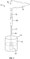
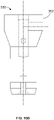
Fig. 1 shows a golf pin and cup assembly with a golf pin connector according to an embodiment of the invention; -
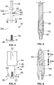
Fig. 2 shows a cross-sectional view through the cup and golf pin connector ofFig. 1 ; -
Fig. 3 shows a schematic view of the base member of the golf pin connector ofFig. 1 ; -
Fig. 4 shows a cross-sectional view of the ferrule of the golf pin connector ofFig. 1 with a golf pin; -
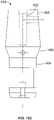
Fig. 5 shows a schematic view of a base member of a golf pin connector according to another embodiment of the invention; -
Fig. 6 shows a cross-sectional view of a ferrule of a golf pin connector according to another embodiment of the invention; -
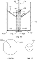
Figs. 7a, 7b and 7c show a cross-sectional view through a cup and a golf pin connector according to another embodiment of the invention, a plan view of the fixing plate ofFig. 7a and a plan view of the washer ofFig. 7a respectively; -
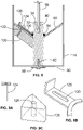
Fig. 8 shows a cross-sectional view through a golf pin and cup assembly including a golf pin connector according to another embodiment of the invention; -
Figs. 9a, 9b and 9c show the locking plate fastener, locking plate and conical ball support stiffener respectively of the golf pin and cup assembly ofFig. 8 -
Figs. 10a ,10b and10c show various base members which may be incorporated in the golf pin connector of the invention; -
Fig. 11 shows a thin shaft which may used in the golf pin connector of the invention; and -
Fig. 12 shows a ferrule which may used in the golf pin connector of the invention. - In
Fig. 1 there is shown a golf pin andcup assembly 10, comprising agolf pin connector 12 removably mounted in acup 14, and agolf pin 16 which is removably connected to thegolf pin connector 12. Thecup 14 is typically installed in a green of a golf course such that itsupper rim 20 is generally flush with or just below the putting surface of the green. Thegolf pin 16 has aflag 19 secured to itstop portion 20. - The
golf pin connector 12 is seen more clearly inFig. 2 . It includes a generallycylindrical base member 30, shown more clearly inFig. 3 , which has an axial lowercylindrical socket 32 arranged in theupper surface 34 of thebase member 30. Typically the base member is of metal, for example stainless steel or an aluminium alloy. It can be formed by machining. However the invention encompasses other materials, such as a moulded plastic material. - Extending upwards from the lower
cylindrical socket 32 is athin shaft 36 having a lower end 38 and anupper end 40. Thelower end 40 of thethin shaft 36 is removably engageable in the lowercylindrical socket 32 of thebase member 30. The lowercylindrical socket 32 is sized such that thethin shaft 36 can be easily located therein. A thinshaft fastening mechanism 42 is used to secure thelower end 40 of the thin shaft in the lowercylindrical socket 32. In the example ofFig. 2 the thinshaft fastening mechanism 42 comprises a threadedaperture 44 in thebase member 30 which extends radially from the outer cylindrical surface of thebase member 30 to the lowercylindrical socket 32 and a lockingscrew 46 which engages in the radial threadedaperture 44 against thelower end 40 of thethin shaft 36. In use the lockingscrew 46 is screwed in to the radial threadedaperture 44 until it bears against thelower end 40 of thethin shaft 36, thereby clamping thethin shaft 36 in thebase member 30. - A
ferrule 50, shown more clearly inFig. 4 , is secured to theupper end 52 of thethin shaft 36 and has an axially extending uppercylindrical socket 54 at its upper end for receiving agolf pin 16, not shown inFig. 2 . At its lower end it has athin shaft socket 56 in which theupper end 52 of thethin shaft 36 is secured, for example by adhesive or other fixing method. Theferrule 50 is typically formed of a single piece of metal, for example stainless steel or an aluminium alloy. It can be formed by machining. However the invention encompasses other materials, such as a moulded plastic material. If required theferrule 50 andthin shaft 36 can be formed as a single piece, so that there is nothin shaft socket 56 used for joining theferrule 50 andthin shaft 36. - The
thin shaft 36 has a diameter of 10 mm or less, typically 8 mm. This diameter is significantly less than that of a conventional golf pin, or indeed of thegolf pin 16 received in the uppercylindrical socket 54 of theferrule 50, which is typically 12.7 mm in diameter. Typically thethin shaft 36 has a length measured between the underside of theferrule 50 and theupper surface 34 of thebase member 30 of between 100 mm and 400 mm, when thelower end 40 of thethin shaft 36 is fully engaged in the lowercylindrical socket 32 and theupper end 52 of thethin shaft 36 is fully engaged in the upper lowercylindrical socket 32. In practice, the inventor has found that the use of athin shaft 36 having a length of 200 mm to 300 mm, preferably about 250 mm, produces a good result, being of sufficient length to provide a thin target for a ball played on the putting green, while being stiff enough to ensure that the top of thegolf pin 16 deflects no more under wind load than a standard golf pin. Typically the lowercylindrical socket 32 has a depth of 30 mm to 60 mm, preferably 45 mm, while thethin shaft socket 56 has a depth of 20 mm to 40 mm, preferably 30 mm, so that the length measured between the underside of theferrule 50 and theupper surface 34 of thebase member 30 is between 100 mm and 250 mm, preferably about 175 mm. - A golfer can enjoy the advantage of the
thin shaft 32 during putting, but thegolf pin connector 12 allows the thicker shaft of aconventional golf pin 16 to be used above theferrule 50, so that theflag 19 andpin 16 may be seen by a golfer from a distance. - The upper
cylindrical socket 54 of the ferrule is circular cylindrical socket with an internal diameter of between 12.7 mm and 13.5 mm, to allow thegolf pin connector 12 to be readily used with astandard golf pin 16 inserted in the uppercylindrical socket 54, cut to length if necessary. If required, thepin 16 can be permanently bonded to theferrule 50, by adhesive or the like. - In an
alternative ferrule 150 shown inFig. 6 , the uppercylindrical socket 54 includes an upper circularcylindrical socket portion 54a with an internal diameter of between 12.7 mm and 13.5 mm and a lowertapering socket portion 54b. Tapering at least part of the socket allows a longer socket length and therefore a stronger connection between thethin shaft 36 and thegolf pin 16. It also allows a reduced outer diameter of theferrule 50, because the diameter of the end of thegolf pin 16 is reduced to fit in the tapered socket, so that the wall thickness of theferrule 150 is increased locally, allowing increased bending strength without increasing the overall diameter of theferrule 150. - Typically the
thin shaft 36 is made of stainless steel or aluminium alloy rod. However it can be made from other materials such as GRP or carbon fibre. Because it has a uniform section, it can be cut from a ready formed rod material. The thin shaft may be painted or coated in a plastic coating, such as a vinyl coating, to provide the required colour. - Typically the
ferrule thin shaft 36 andferrule ferrule 50 can be formed by welding a tubular upper part to a machined or cast lower part. - The
ferrule Fig. 4 or 90 mm in the embodiment ofFig. 6 . Typically the uppercylindrical socket 54 and thethin shaft socket 56 are about 30 mm in length. The uppercylindrical socket 54 may be longer, say 40 mm in length, if it includes both cylindrical andtapered portions - The ferrule may have a maximum external diameter of 20 mm, preferably 18 mm or less. Typically the
ferrule 50 in the embodiment ofFig. 4 has a maximum external diameter of about 16 mm, and theferrule 150 in the embodiment ofFig. 6 has a maximum external diameter of about 19 mm. Because theferrule - In order to provide a smooth external finish to the
golf pin connector 12, the external diameter of theferrule - Turning again to the
base member 30, shown in more detail inFig. 3 , thebase member 30 is substantially cylindrical in shape, with an outside diameter of between 20 and 30 mm. Preferably the outside diameter is 26 mm, so that thebase member 30 can fit in a standard inside round flag aperture found on conventional golf cups. As can be seen inFig. 2 thecup 14 has a conicalball support surface 60 which extends from the cylindrical wall of thecup 14 down to acentral aperture 62, within which the base of a conventional golf pin may be placed. Optionally thecentral aperture 62 includes a cylindrical wall (not shown) extending downwards from the aperture in the conicalball support surface 60. Thebase member 30 has a circumferential rib orflange 64 at its outer surface, which allows it to sit securely on thecentral aperture 62 provided in the conicalball support surface 60. The rib orflange 64 may also be used to secure thebase member 30 in thecup 14, as is described below. - The
base member 30 includes an uppercylindrical portion 30a a extending above the circumferential rib orflange 64 for a height of between 20 mm and 50 mm, and a lowercylindrical portion 30b. In the illustrated example the uppercylindrical portion 30a, like the lowercylindrical portion 30b, has a diameter of about 26 mm, and it has a height above the circumferential rib orflange 64 of 30 mm. In the illustrated example therib 64 has a height of 15 mm, although this could be less or more, for example between 5 mm and 25 mm, and projects radially from the cylindrical base member by 5 mm, although this could be any suitable dimension, for example 10 mm. - The upper
cylindrical portion 30a projects above the aperture provided in the conicalball support surface 60, as seen inFig. 2 . The spacing between the wall of thecup 14 and the uppercylindrical portion 30a is less than the diameter of a golf ball, so a ball is prevented from falling completely between thecylindrical portion 30a and the wall of thecup 14, thereby making retrieval of the ball easier. - The total height of the circumferential rib or flange and the cylindrical portion extending above the circumferential rib or flange may be between 25 mm and 80 mm. In the illustrated example the total height is 45 mm. This dimension ensures that a ball falls cleanly into the cup, but allows the ball to sit about 30 mm higher than in a conventional cup with a conventional pin therein.
- In the illustrated embodiment of
Fig. 3 the thin shaft fastening mechanism comprises a lockingscrew 46 with a hexagonal head which can be turned by a ratchet or spanner inserted into thecup 14, to lock or unlock thethin shaft 36 in thebase member 30. The head of the lockingscrew 46 may have one or more optionaltransverse apertures 66 in which a tool may be inserted to rotate the lockingscrew 46. Alternatively the lockingscrew 46 may be provided with any suitable drive means which can be accessed using a suitable tool from outside thecup 14. - In another embodiment of the
base member 30 illustrated inFig. 7b , the thin shaft fastening mechanism comprises a retainingmember 70 adapted to retain thelower end 40 of thethin shaft 36 in the lowercylindrical socket 32. The retainingmember 70 is operated to permit removal of thelower end 40 of thethin shaft 36 from the lowercylindrical socket 32. In the illustrated example the retainingmember 70 is a resilient detent structure which is resiliently biased by a spring means 72 in the direction ofarrow 74 to engage with arecess 76 in thethin shaft 36. Therecess 76 may extend part or all of the way around the circumference of thethin shaft 36, and may form a slot. By application of pressure by a suitable tool on the retainingmember 70, the engaging means (in this example the tip of the engaging member 70) is removed from therecess 76 in thethin shaft 36, thereby permitting thethin shaft 36 to be removed from the lowercylindrical socket 32. The engaging means 70 may automatically engage with the lower end of thethin shaft 36, for example by biasing action, when the thin shaft is replaced in the lowercylindrical socket 32. To that end the engaging means may be rounded, to form a detent action. - Other methods of securing the
lower end 40 of thethin shaft 36 in the lowercylindrical socket 32. For example, thelower end 40 of thethin shaft 36 and the lowercylindrical socket 32 may be shaped to engage securely with each other, either by axial movement or rotational movement. The thin shaft fastening mechanism may comprise corresponding thread or bayonet structures (not shown) on thelower end 40 of thethin shaft 36 and the lowercylindrical socket 32, so that thethin shaft 40 is engaged in thebase member 30 by twisting thethin shaft 40. - The thin shaft fastening mechanism allows the
golf pin connector 12, with or without the attachedgolf pin 16, to be removed by the use of an appropriate tool or an appropriate removal technique, for example when a groundsman is cutting the grass on the green in which thecup 14 andgolf pin connector 12 are located. Thegolf pin connector 12 can be easily replaced in thecup 14 thereafter by the reverse process. - A further embodiment of a
base member 30 is shown inFig. 5 . In this embodiment thebase member 30 includes awaist portion 78 of reduced diameter. This allows a reduction in weight and material for the base member. The upper and lowerthicker portions central aperture 62 of thepin 14. A number ofvertical drainage channels 82 are formed around the circumference of thelower portion 82. If thebase member 30 is used with acentral aperture 62 having a tubular wall, the upper and lowerthicker portions central aperture 62, but any moisture will pass through the gap between thewaist portion 78 and the wall of thecentral aperture 62, and can drain away through thedrainage channels 82. If thebase member 30 is left in thecup 14 for a long time, thewaist portion 78 and drainage channels prevent water being trapped between thebase member 30 and thecentral aperture 62, so retrieval of thebase member 30 from thecup 14 is made easier. - The
cup 14 may be a closed cup, having a fixedcup base 90 extending across the bottom of the cup, as shown inFig. 2 , or an open cup, having an openlower end 100, as shown inFig. 7a . Abase fastener 92, which in the illustrated example is a threaded fastener, is used to secure thebase member 30 to thecup 14. - With reference to
Fig. 2 , thecup base 90 has anaperture 94 therein for receiving the threadedfastener 92, and thebase member 30 has a central, axial threadedaperture 96 therein for receiving the threadedfastener 92. Thebase member 30 is fixed to thecup 14 by removing thecup 14 from the ground and inserting the threadedfastener 92 through awasher 98 and through theaperture 94 in thecup base 90, and screwing it into theaperture 96 in thebase member 30. In the embodiment ofFig. 2 the base member is then supported by both the rib orflange 64 and thefastener 92. - If the
base member 30 is supported against the conicalball support surface 60 by the rib orflange 64, but does not extend all the way to thecup base 90, then thefastener 92 is tightened until the rib orflange 64 sits firmly against the conicalball support surface 60. - In the embodiment of
Figs. 7a, 7b and 7c , thecup 14 has an openlower end 100 and no cup base. The golf pin andcup assembly 10 further comprises a fixingplate 102 having a maximum dimension greater than the diameter of the openlower end 100 of thecup 14. The base fastener comprises a threadedfastener 104, the fixing plate has acentral aperture 106 therein for receiving the threadedfastener 104, and thebase member 30 has a central threadedaperture 108 therein for receiving the threadedfastener 104. Thebase member 30 is fixed to thecup 14 by removing thecup 14 from the ground, placing the fixingplate 102 against the cylindrical wall of the cup at itslower end 100, inserting the threaded fastener through anoptional washer 110 and theaperture 106 in the fixingplate 102, and screwing it into theaperture 108 in thebase member 30. - The fixing
plate 102 is narrower than the diameter of the openlower end 100 of thecup 14 in a transverse direction, so that water can drain from the cup around the fixing plate. Alternatively the fixingplate 102 may be provided with apertures for drainage. -
Figs. 8, 9a, 9b and 9c show an embodiment in which alocking plate 120 is provided to secure thebase member 30 within thecup 14. The lockingplate 120 can be used as a base fastener instead of the threadedfastener 104, or can be used as an additional base fastener with the threadedfastener 104. The lockingplate 120 is adapted to engage with the rib orflange 64 provided on the outer surface of thebase member 30. Anaperture 122 is provided on the conicalball support surface 60 of the cup, and alocking plate fastener 124, in this example a threaded fastener, is engageable in theaperture 122 to secure thelocking plate 120 to the conicalball support surface 60. To stiffen the conicalball support surface 60, a reinforcingmember 126 may be provided beneath the conicalball support surface 60, and it can be secured by bonding or welding or the like. The reinforcingmember 126 may have a threadedaperture 128 to receive thelocking plate fastener 124. Aslot 130 is provided in thelocking plate 120 so that once thefastener 124 is partially unthreaded, the plate can be slid in a radial direction away from the rib orflange 64, so that it no longer engages the rib orflange 64, and thebase member 30 can be lifted out of thecup 14, without fully removing thelocking plate fastener 124. - The
base member 30 can thus be locked to thecup 14 to prevent its unauthorised removal. - Referring to
Fig. 10a , there is shown abase member 230 which may be used in the connector of the invention. Like the base member ofFig. 3 , thebase member 230 is generally cylindrical, and has an axially lowercylindrical socket 232 arranged in the upper surface of thebase member 230. Like the embodiment ofFig. 3 the lowercylindrical socket 232 is arranged to receive a thin shaft (not shown) such as theshaft 36 described above. The thin shaft may be secured in position within thesocket 232 by way of a thin shaft fastening mechanism. The thin shaft fastening mechanism comprises a threadedaperture 244 in thebase member 230 which extends radially from the outer surface of thebase member 230 to the lowercylindrical socket 232 and a locking screw (not shown) which engages in the radial threadedaperture 244 against the lower end of the thin shaft. - A
bottom portion 250 of thebase member 230 is secured in position within a cup (not shown) with abase fastener 292, which in the illustrated example is a threaded fastener 290. Above thebottom portion 250 of the base member is acylindrical portion 252 of the base member, which has a smaller diameter than the bottom portion. - The
cylindrical portion 252 comprises aflange portion 254. Above theflange portion 254 is an outwardly taperingportion 256 of the base member which tapers outwardly to where it meets an inwardly taperingportion 258 of the base member. As shown thebase member 230 has its greatest diameter where the outwardly and inwardly taperingportions portion 258 tapers inwardly to a top of thebase member 230. As shown, thecylindrical socket 232 extends downwards from the top of thebase member 230 through the inwardly tapering, outwardly tapering andflange portions - Referring to
Fig. 10b , there is shown afurther base member 330, which may be used in the connector of the invention. Thebase member 330 is essentially the same as thebase member 230. However, in thebase member 330 the inwardly taperingportion 258 is replaced with a topcylindrical portion 352. In other words, the top portion of thebase member 330 is cylindrical. - Referring to
Fig. 10c , there is shown afurther base member 430, which may be used in the connector of the invention. Thebase member 430 is essentially the same as thebase member 230. However, in thebase member 430 the inwardly taperingportion 458 is much longer (in the axial direction) when compared to the inwardly taperingportion 258 of thebase member 230, and thecylindrical socket 432 does not extend into the outwardly tapering andflange portions - Referring to
Fig. 11 , there is shown a thin shaft (or shaft) 436 which may be received in the socket of each of the base members described above. In the illustrated example, the thin shaft comprises arecess 476 which extends all of the way around the circumference of thethin shaft 436 and forms a slot. In use, an engaging member such as the locking screw described above engages the recess. - Referring to
Fig. 12 , there is shown a ferrule which may be used in the connector of the invention. Theferrule 550 is arranged to be secured to the upper end of the thin shaft and has an axially extending uppercylindrical socket 554 at its upper end for receiving a golf pin (not shown). At its lower end it has athin shaft socket 556 in which the upper end 552 of the thin shaft (not shown) is secured, for example by adhesive or other fixing method. Theferrule 550 is typically formed of a single piece of metal, for example stainless steel or an aluminium alloy. It can be formed by machining. However the invention encompasses other materials, such as a moulded plastic material. - The invention offers a number of benefits. For the golfer, the reduced diameter of the
thin shaft 36 means that a ball goes into thecup 14 easily when striking thethin shaft 36. The provision of a base member which projects above theaperture 62 in the conicalball support surface 60 and the slenderness of thethin shaft 36 provides more space for a hand to retrieve a ball from thecup 14. In particular the extra height of thebase member 30 above theflange 64 allows the ball to sit higher in the cup, making retrieval of the ball easier, since the ball cannot pass between thebase member 30 and the wall of thecup 14. Typically a 30mm projection above theflange 64 may result in the ball sitting 30 mm higher in the cup. - If the
golf pin connector 12 is fixed in thecup 14, play is speeded up because the pin is not being removed and replaced in play for different players. Thegolf pin connector 12 is well supported within the centre of thecup 14, so that thegolf pin 16 remains centrally located over the cup. - For the greenkeeper, the fact that the
golf pin connector 12 remains fixed in thecup 14 means that there is less wear and tie arising from repeated removal and replacement of a pin in the cup, and less damage to the cup and pin from careless players. Thegolf pin connector 12 offers an easy release system to allow removal of thegolf pin connector 12 andpin 16 for green maintenance. Thegolf pin connector 12 remains centrally located in the cup so there is less damage to the grass around the cup due to careless removal and replacement of the pin. Thegolf pin connector 12 is cost effective, lasts longer than conventional pins and can be used with any conventional cups and flags. - For spectators and TV broadcasters, the fact that the
golf pin connector 12 remains centrally located in the cup improves the viewing experience, especially from a distance, because the position of thecup 14 can always be identified. With conventional golf pins, when players are putting with the pin out, it is difficult to see where thecup 14 is. - The invention is not limited such that it is only for use with grass golf courses. It may equally be implemented for some or all of the above mentioned benefits in mini golf courses, crazy golf courses, golf courses with artificial surfaces, or any other type of golf course.
- The invention is not limited to the materials listed herein. Any suitable materials may be used.
- The invention is defined only by the appended claims.
Claims (15)
- A golf pin connector (12) comprising:a base member (30) having a lower cylindrical socket therein extending from an upper surface of the base member,a thin shaft (36) having a lower end and an upper end, the lower end of the thin shaft being removably engageable in the lower cylindrical socket of the base member,a thin shaft fastening mechanism (42) adapted to secure the lower end of the thin shaft in the lower cylindrical socket of the base member, anda ferrule (50) secured to the upper end of the thin shaft and having an upper cylindrical socket for receiving a golf pin;characterised in that,the thin shaft has a diameter of 10 mm or less, preferably 8 mm or less.
- The golf pin connector of claim 1, wherein the thin shaft has a length measured between the ferrule and the base member when the lower end of the shaft is fully engaged in the lower cylindrical socket of the base member of between 100 mm and 400 mm.
- The golf pin connector of claim 1 or 2, wherein the upper cylindrical socket includes one or both of an upper circular cylindrical socket portion with an internal diameter of between 12.7 mm and 13.5 mm and a lower tapering socket portion.
- The golf pin connector of any preceding claim, wherein the ferrule has a thin shaft socket within which the upper end of the thin shaft is secured, the thin shaft socket being arranged at an opposite end to the upper cylindrical socket.
- The golf pin connector of any preceding claim, wherein the ferrule is a one-piece metal component with a circular external shape in cross-section, preferably with a maximum external diameter of 20 mm.
- The golf pin connector of claim 5, wherein the external diameter of the ferrule tapers over at least part of its length such that the external diameter is less at the lower end than at the centre thereof.
- The golf pin connector of any preceding claim, wherein the base member has a circumferential rib or flange at its outer surface.
- The golf pin connector of claim 7, wherein the base member comprises a cylindrical portion extending above the circumferential rib or flange for a height of between 20 mm and 50 mm.
- The golf pin connector of claim 8, wherein the total height of the circumferential rib or flange (64) and the cylindrical portion extending above the circumferential rib or flange is between 25 mm and 80 mm.
- The golf pin connector of any preceding claim, wherein the thin shaft fastening mechanism comprises a radial threaded aperture (44) in the base member extending to the lower cylindrical socket and a locking screw (46) adapted to engage in the radial threaded aperture against the lower end of the thin shaft.
- The golf pin connector of any of claims 1 to 9, wherein the thin shaft fastening mechanism comprises a retaining member (70) adapted to retain the lower end of the thin shaft in the lower cylindrical socket, and wherein the retaining member is operable to permit removal of the lower end of the thin shaft from the lower cylindrical socket.
- A golf pin assembly comprising a golf pin connector (12) according to any preceding claim and a golf pin (16) which is removably engageable in the upper cylindrical socket of the ferrule.
- A golf pin and cup assembly comprising a golf pin connector (12) according to any preceding claim, a golf pin (16) which is removably engageable in the upper cylindrical socket of the ferrule, and a cup (14), wherein the base member is removably engageable in the cup.
- A golf pin and cup assembly according to claim 13, wherein the cup comprises a cylindrical wall and a conical ball support surface extending from an inner surface of the cylindrical wall, wherein the conical ball support surface has a central aperture adapted to receive the base member therein, and wherein the assembly comprises a base fastener for securing the base member to the cup.
- A golf pin and cup assembly according to claim 13 or 14, wherein:the cup comprises a cup base,the base fastener comprises a threaded fastener,the cup base has an aperture therein for receiving the threaded fastener, andthe base member has a central threaded aperture therein for receiving the threaded fastener.
Applications Claiming Priority (2)
| Application Number | Priority Date | Filing Date | Title |
|---|---|---|---|
| GBGB1909770.8A GB201909770D0 (en) | 2019-07-08 | 2019-07-08 | Apparatus for securing a golf pin to a golf cup |
| PCT/GB2020/051627 WO2021005355A1 (en) | 2019-07-08 | 2020-07-07 | Apparatus for securing a thin pin to a flag stick and hole cup |
Publications (2)
| Publication Number | Publication Date |
|---|---|
| EP3969133A1 EP3969133A1 (en) | 2022-03-23 |
| EP3969133B1 true EP3969133B1 (en) | 2022-06-22 |
Family
ID=67623291
Family Applications (1)
| Application Number | Title | Priority Date | Filing Date |
|---|---|---|---|
| EP20742373.2A Revoked EP3969133B1 (en) | 2019-07-08 | 2020-07-07 | Apparatus for securing a thin pin to a flag stick and hole cup |
Country Status (3)
| Country | Link |
|---|---|
| EP (1) | EP3969133B1 (en) |
| GB (1) | GB201909770D0 (en) |
| WO (1) | WO2021005355A1 (en) |
Citations (6)
| Publication number | Priority date | Publication date | Assignee | Title |
|---|---|---|---|---|
| GB229114A (en) | 1924-03-10 | 1925-02-19 | David Kennedy | Improvements in and relating to flag-posts for golf holes |
| US4691922A (en) | 1986-03-10 | 1987-09-08 | Peel Robert M | Golf practice device |
| US20050272515A1 (en) | 2004-06-04 | 2005-12-08 | Standard Golf Company | Golf flagstick assembly and method of joining |
| US20160320050A1 (en) | 2015-04-29 | 2016-11-03 | More Useless Tools, Inc. | Portable lighting apparatus and carrying rack |
| WO2016210149A1 (en) | 2015-06-25 | 2016-12-29 | Greg Kelly | Ferrule housing for a golf cup |
| US10173118B1 (en) | 2017-11-15 | 2019-01-08 | Gerard Lawrence | Foldable target game |
-
2019
- 2019-07-08 GB GBGB1909770.8A patent/GB201909770D0/en not_active Ceased
-
2020
- 2020-07-07 EP EP20742373.2A patent/EP3969133B1/en not_active Revoked
- 2020-07-07 WO PCT/GB2020/051627 patent/WO2021005355A1/en not_active Ceased
Patent Citations (6)
| Publication number | Priority date | Publication date | Assignee | Title |
|---|---|---|---|---|
| GB229114A (en) | 1924-03-10 | 1925-02-19 | David Kennedy | Improvements in and relating to flag-posts for golf holes |
| US4691922A (en) | 1986-03-10 | 1987-09-08 | Peel Robert M | Golf practice device |
| US20050272515A1 (en) | 2004-06-04 | 2005-12-08 | Standard Golf Company | Golf flagstick assembly and method of joining |
| US20160320050A1 (en) | 2015-04-29 | 2016-11-03 | More Useless Tools, Inc. | Portable lighting apparatus and carrying rack |
| WO2016210149A1 (en) | 2015-06-25 | 2016-12-29 | Greg Kelly | Ferrule housing for a golf cup |
| US10173118B1 (en) | 2017-11-15 | 2019-01-08 | Gerard Lawrence | Foldable target game |
Non-Patent Citations (10)
| Title |
|---|
| "2019 rules changes to know: Why the flagstick is now your friend", GOLF.COM ARTICLE, 24 December 2018 (2018-12-24), Retrieved from the Internet <URL:https://golf.com/instruction/2019-rules-changes-leave-flagstick-putting> |
| "New for 2019: The Putt-Saver, two-piece Tournament Flagstick", STANDARD GOLF ARTICLE, 30 January 2019 (2019-01-30), Retrieved from the Internet <URL:https://www.standardgolf.com/new-for-2019-the-putt-saver-two-piece- tourna ment-flag stick> |
| "Putt -saver Tournament Flagstick, permitted under the Rules of Golf", STANDARD GOLF ARTICLE, 23 April 2019 (2019-04-23), Retrieved from the Internet <URL:https: / /www.standardgolf.com/putt-saver-tournament-flagstick-perm itted-under- the-ru les-of-golf> |
| "Standard Flag Pin", FAIRWAY PRODUCTS, Retrieved from the Internet <URL:https://www.fairwayproductsonline.co.uk/golf-flag-pins-and-hole-placement- markers/standard-flag-pin> |
| "Standard Golf announces its new flagstick conforms to the Rules of Golf", GOLF COURSE INDUSTRY ARTICLE, 29 April 2019 (2019-04-29), Retrieved from the Internet <URL:https://www.golfcourseindustry.com/news/standard-qolf-putt- saver/ #: ~: text= First%2C%20the%20tapered%20flagstick%20is,back%20to%203%2F 8%22> |
| "standard plastic hole cup", FAIRWAY PRODUCTS, Retrieved from the Internet <URL:https://www.fairwayproductsonline.co.uk/hole-cups,holecutters-and- accessories/standard-plastic-hole-cup> |
| FACEBOOK, 20 January 2020 (2020-01-20), Retrieved from the Internet <URL:https://www.facebook.com/thinpingolf> |
| STANDARD GOLF ADVERTISING BROCHURE, 1938 |
| STANDARD GOLF ADVERTISING BROCHURE, 1958 |
| STANDARD GOLF ALUMINUM GOLF CUP, Retrieved from the Internet <URL:https:/ /www.standardgolf.com/ecommerce/p/alumi num -cup-183A> |
Also Published As
| Publication number | Publication date |
|---|---|
| EP3969133A1 (en) | 2022-03-23 |
| GB201909770D0 (en) | 2019-08-21 |
| WO2021005355A1 (en) | 2021-01-14 |
Similar Documents
| Publication | Publication Date | Title |
|---|---|---|
| US9968833B2 (en) | Golf club with adjustable weight assembly | |
| US9433836B2 (en) | Golf club with adjustable weight assembly | |
| EP2367602B1 (en) | Golf club head having interchangeable rear body members, method for assembling such a golf club head, and corresponding kit | |
| KR100863259B1 (en) | Structure of a golf club head or other ball striking device | |
| US4067572A (en) | Golf club | |
| KR101196508B1 (en) | Releasable and interchangeable connections for golf club heads and shafts | |
| US12521609B2 (en) | Golf clubs and golf club heads having interchangeable rear body members | |
| US10322321B2 (en) | Golf clubs and golf club heads having interchangeable rear body members | |
| US8608585B2 (en) | Golf club head or other ball striking device having a reinforced or localized stiffened face portion | |
| US20110009210A1 (en) | Golf Clubs And Golf Club Heads Having Adjustable Weight Members | |
| US7455594B1 (en) | Ferrule and sleeve assembly | |
| US20120208653A1 (en) | Golf club and method for adjusting characteristics of golf club | |
| WO1988002642A1 (en) | Golf club head | |
| US11697049B2 (en) | Golf ball retrieval device | |
| US12138514B2 (en) | Height-adjustable golf tee system | |
| US12478844B1 (en) | Golf bell | |
| EP3969133B1 (en) | Apparatus for securing a thin pin to a flag stick and hole cup | |
| US20120184387A1 (en) | Golf flagstick with capped ferrule | |
| US11185748B2 (en) | Golf ball retrieving device | |
| US20220219055A1 (en) | System comprising a flagstick and a ferrule for marking a golf hole and a ferrule for use in such a system | |
| KR102901131B1 (en) | Golf tee with adjustable angle | |
| KR200349261Y1 (en) | Rotatable golf tee | |
| EP3009172B1 (en) | Golf teeing aid | |
| JP2024510178A (en) | height adjustable golf tee system | |
| JP2004357913A (en) | Golf tee holder and holder driving fixture |
Legal Events
| Date | Code | Title | Description |
|---|---|---|---|
| STAA | Information on the status of an ep patent application or granted ep patent |
Free format text: STATUS: UNKNOWN |
|
| STAA | Information on the status of an ep patent application or granted ep patent |
Free format text: STATUS: THE INTERNATIONAL PUBLICATION HAS BEEN MADE |
|
| PUAI | Public reference made under article 153(3) epc to a published international application that has entered the european phase |
Free format text: ORIGINAL CODE: 0009012 |
|
| STAA | Information on the status of an ep patent application or granted ep patent |
Free format text: STATUS: REQUEST FOR EXAMINATION WAS MADE |
|
| 17P | Request for examination filed |
Effective date: 20211214 |
|
| AK | Designated contracting states |
Kind code of ref document: A1 Designated state(s): AL AT BE BG CH CY CZ DE DK EE ES FI FR GB GR HR HU IE IS IT LI LT LU LV MC MK MT NL NO PL PT RO RS SE SI SK SM TR |
|
| GRAP | Despatch of communication of intention to grant a patent |
Free format text: ORIGINAL CODE: EPIDOSNIGR1 |
|
| STAA | Information on the status of an ep patent application or granted ep patent |
Free format text: STATUS: GRANT OF PATENT IS INTENDED |
|
| INTG | Intention to grant announced |
Effective date: 20220413 |
|
| GRAS | Grant fee paid |
Free format text: ORIGINAL CODE: EPIDOSNIGR3 |
|
| GRAA | (expected) grant |
Free format text: ORIGINAL CODE: 0009210 |
|
| STAA | Information on the status of an ep patent application or granted ep patent |
Free format text: STATUS: THE PATENT HAS BEEN GRANTED |
|
| AK | Designated contracting states |
Kind code of ref document: B1 Designated state(s): AL AT BE BG CH CY CZ DE DK EE ES FI FR GB GR HR HU IE IS IT LI LT LU LV MC MK MT NL NO PL PT RO RS SE SI SK SM TR |
|
| DAV | Request for validation of the european patent (deleted) | ||
| DAX | Request for extension of the european patent (deleted) | ||
| REG | Reference to a national code |
Ref country code: GB Ref legal event code: FG4D |
|
| REG | Reference to a national code |
Ref country code: CH Ref legal event code: EP |
|
| REG | Reference to a national code |
Ref country code: DE Ref legal event code: R096 Ref document number: 602020003687 Country of ref document: DE |
|
| REG | Reference to a national code |
Ref country code: AT Ref legal event code: REF Ref document number: 1499384 Country of ref document: AT Kind code of ref document: T Effective date: 20220715 |
|
| REG | Reference to a national code |
Ref country code: IE Ref legal event code: FG4D |
|
| REG | Reference to a national code |
Ref country code: LT Ref legal event code: MG9D |
|
| REG | Reference to a national code |
Ref country code: NL Ref legal event code: MP Effective date: 20220622 |
|
| PG25 | Lapsed in a contracting state [announced via postgrant information from national office to epo] |
Ref country code: SE Free format text: LAPSE BECAUSE OF FAILURE TO SUBMIT A TRANSLATION OF THE DESCRIPTION OR TO PAY THE FEE WITHIN THE PRESCRIBED TIME-LIMIT Effective date: 20220622 Ref country code: NO Free format text: LAPSE BECAUSE OF FAILURE TO SUBMIT A TRANSLATION OF THE DESCRIPTION OR TO PAY THE FEE WITHIN THE PRESCRIBED TIME-LIMIT Effective date: 20220922 Ref country code: LT Free format text: LAPSE BECAUSE OF FAILURE TO SUBMIT A TRANSLATION OF THE DESCRIPTION OR TO PAY THE FEE WITHIN THE PRESCRIBED TIME-LIMIT Effective date: 20220622 Ref country code: HR Free format text: LAPSE BECAUSE OF FAILURE TO SUBMIT A TRANSLATION OF THE DESCRIPTION OR TO PAY THE FEE WITHIN THE PRESCRIBED TIME-LIMIT Effective date: 20220622 Ref country code: GR Free format text: LAPSE BECAUSE OF FAILURE TO SUBMIT A TRANSLATION OF THE DESCRIPTION OR TO PAY THE FEE WITHIN THE PRESCRIBED TIME-LIMIT Effective date: 20220923 Ref country code: FI Free format text: LAPSE BECAUSE OF FAILURE TO SUBMIT A TRANSLATION OF THE DESCRIPTION OR TO PAY THE FEE WITHIN THE PRESCRIBED TIME-LIMIT Effective date: 20220622 Ref country code: BG Free format text: LAPSE BECAUSE OF FAILURE TO SUBMIT A TRANSLATION OF THE DESCRIPTION OR TO PAY THE FEE WITHIN THE PRESCRIBED TIME-LIMIT Effective date: 20220922 |
|
| PGFP | Annual fee paid to national office [announced via postgrant information from national office to epo] |
Ref country code: IE Payment date: 20220727 Year of fee payment: 3 Ref country code: DE Payment date: 20220726 Year of fee payment: 3 |
|
| REG | Reference to a national code |
Ref country code: AT Ref legal event code: MK05 Ref document number: 1499384 Country of ref document: AT Kind code of ref document: T Effective date: 20220622 |
|
| PG25 | Lapsed in a contracting state [announced via postgrant information from national office to epo] |
Ref country code: RS Free format text: LAPSE BECAUSE OF FAILURE TO SUBMIT A TRANSLATION OF THE DESCRIPTION OR TO PAY THE FEE WITHIN THE PRESCRIBED TIME-LIMIT Effective date: 20220622 Ref country code: LV Free format text: LAPSE BECAUSE OF FAILURE TO SUBMIT A TRANSLATION OF THE DESCRIPTION OR TO PAY THE FEE WITHIN THE PRESCRIBED TIME-LIMIT Effective date: 20220622 |
|
| PGFP | Annual fee paid to national office [announced via postgrant information from national office to epo] |
Ref country code: FR Payment date: 20220728 Year of fee payment: 3 |
|
| PG25 | Lapsed in a contracting state [announced via postgrant information from national office to epo] |
Ref country code: NL Free format text: LAPSE BECAUSE OF FAILURE TO SUBMIT A TRANSLATION OF THE DESCRIPTION OR TO PAY THE FEE WITHIN THE PRESCRIBED TIME-LIMIT Effective date: 20220622 |
|
| PG25 | Lapsed in a contracting state [announced via postgrant information from national office to epo] |
Ref country code: SM Free format text: LAPSE BECAUSE OF FAILURE TO SUBMIT A TRANSLATION OF THE DESCRIPTION OR TO PAY THE FEE WITHIN THE PRESCRIBED TIME-LIMIT Effective date: 20220622 Ref country code: SK Free format text: LAPSE BECAUSE OF FAILURE TO SUBMIT A TRANSLATION OF THE DESCRIPTION OR TO PAY THE FEE WITHIN THE PRESCRIBED TIME-LIMIT Effective date: 20220622 Ref country code: RO Free format text: LAPSE BECAUSE OF FAILURE TO SUBMIT A TRANSLATION OF THE DESCRIPTION OR TO PAY THE FEE WITHIN THE PRESCRIBED TIME-LIMIT Effective date: 20220622 Ref country code: PT Free format text: LAPSE BECAUSE OF FAILURE TO SUBMIT A TRANSLATION OF THE DESCRIPTION OR TO PAY THE FEE WITHIN THE PRESCRIBED TIME-LIMIT Effective date: 20221024 Ref country code: ES Free format text: LAPSE BECAUSE OF FAILURE TO SUBMIT A TRANSLATION OF THE DESCRIPTION OR TO PAY THE FEE WITHIN THE PRESCRIBED TIME-LIMIT Effective date: 20220622 Ref country code: EE Free format text: LAPSE BECAUSE OF FAILURE TO SUBMIT A TRANSLATION OF THE DESCRIPTION OR TO PAY THE FEE WITHIN THE PRESCRIBED TIME-LIMIT Effective date: 20220622 Ref country code: CZ Free format text: LAPSE BECAUSE OF FAILURE TO SUBMIT A TRANSLATION OF THE DESCRIPTION OR TO PAY THE FEE WITHIN THE PRESCRIBED TIME-LIMIT Effective date: 20220622 Ref country code: AT Free format text: LAPSE BECAUSE OF FAILURE TO SUBMIT A TRANSLATION OF THE DESCRIPTION OR TO PAY THE FEE WITHIN THE PRESCRIBED TIME-LIMIT Effective date: 20220622 |
|
| PG25 | Lapsed in a contracting state [announced via postgrant information from national office to epo] |
Ref country code: PL Free format text: LAPSE BECAUSE OF FAILURE TO SUBMIT A TRANSLATION OF THE DESCRIPTION OR TO PAY THE FEE WITHIN THE PRESCRIBED TIME-LIMIT Effective date: 20220622 Ref country code: IS Free format text: LAPSE BECAUSE OF FAILURE TO SUBMIT A TRANSLATION OF THE DESCRIPTION OR TO PAY THE FEE WITHIN THE PRESCRIBED TIME-LIMIT Effective date: 20221022 |
|
| REG | Reference to a national code |
Ref country code: DE Ref legal event code: R026 Ref document number: 602020003687 Country of ref document: DE |
|
| PLBI | Opposition filed |
Free format text: ORIGINAL CODE: 0009260 |
|
| REG | Reference to a national code |
Ref country code: BE Ref legal event code: MM Effective date: 20220731 |
|
| PG25 | Lapsed in a contracting state [announced via postgrant information from national office to epo] |
Ref country code: MC Free format text: LAPSE BECAUSE OF FAILURE TO SUBMIT A TRANSLATION OF THE DESCRIPTION OR TO PAY THE FEE WITHIN THE PRESCRIBED TIME-LIMIT Effective date: 20220622 Ref country code: AL Free format text: LAPSE BECAUSE OF FAILURE TO SUBMIT A TRANSLATION OF THE DESCRIPTION OR TO PAY THE FEE WITHIN THE PRESCRIBED TIME-LIMIT Effective date: 20220622 |
|
| PLAX | Notice of opposition and request to file observation + time limit sent |
Free format text: ORIGINAL CODE: EPIDOSNOBS2 |
|
| 26 | Opposition filed |
Opponent name: FAIRWAY PRODUCTS (UK) LIMITED Effective date: 20230320 |
|
| PG25 | Lapsed in a contracting state [announced via postgrant information from national office to epo] |
Ref country code: LU Free format text: LAPSE BECAUSE OF NON-PAYMENT OF DUE FEES Effective date: 20220707 Ref country code: DK Free format text: LAPSE BECAUSE OF FAILURE TO SUBMIT A TRANSLATION OF THE DESCRIPTION OR TO PAY THE FEE WITHIN THE PRESCRIBED TIME-LIMIT Effective date: 20220622 |
|
| PG25 | Lapsed in a contracting state [announced via postgrant information from national office to epo] |
Ref country code: BE Free format text: LAPSE BECAUSE OF NON-PAYMENT OF DUE FEES Effective date: 20220731 |
|
| RDAF | Communication despatched that patent is revoked |
Free format text: ORIGINAL CODE: EPIDOSNREV1 |
|
| REG | Reference to a national code |
Ref country code: DE Ref legal event code: R103 Ref document number: 602020003687 Country of ref document: DE Ref country code: DE Ref legal event code: R064 Ref document number: 602020003687 Country of ref document: DE |
|
| PG25 | Lapsed in a contracting state [announced via postgrant information from national office to epo] |
Ref country code: IT Free format text: LAPSE BECAUSE OF FAILURE TO SUBMIT A TRANSLATION OF THE DESCRIPTION OR TO PAY THE FEE WITHIN THE PRESCRIBED TIME-LIMIT Effective date: 20220622 |
|
| REG | Reference to a national code |
Ref country code: CH Ref legal event code: PL |
|
| RDAG | Patent revoked |
Free format text: ORIGINAL CODE: 0009271 |
|
| STAA | Information on the status of an ep patent application or granted ep patent |
Free format text: STATUS: PATENT REVOKED |
|
| REG | Reference to a national code |
Ref country code: CH Ref legal event code: PL |
|
| 27W | Patent revoked |
Effective date: 20231209 |
|
| GBPR | Gb: patent revoked under art. 102 of the ep convention designating the uk as contracting state |
Effective date: 20231209 |
|
| REG | Reference to a national code |
Ref country code: IE Ref legal event code: MM4A |
|
| PG25 | Lapsed in a contracting state [announced via postgrant information from national office to epo] |
Ref country code: MK Free format text: LAPSE BECAUSE OF FAILURE TO SUBMIT A TRANSLATION OF THE DESCRIPTION OR TO PAY THE FEE WITHIN THE PRESCRIBED TIME-LIMIT Effective date: 20220622 Ref country code: CY Free format text: LAPSE BECAUSE OF FAILURE TO SUBMIT A TRANSLATION OF THE DESCRIPTION OR TO PAY THE FEE WITHIN THE PRESCRIBED TIME-LIMIT Effective date: 20220622 Ref country code: CH Free format text: LAPSE BECAUSE OF NON-PAYMENT OF DUE FEES Effective date: 20230731 |
|
| PG25 | Lapsed in a contracting state [announced via postgrant information from national office to epo] |
Ref country code: FR Free format text: LAPSE BECAUSE OF NON-PAYMENT OF DUE FEES Effective date: 20230731 |
|
| PG25 | Lapsed in a contracting state [announced via postgrant information from national office to epo] |
Ref country code: MT Free format text: LAPSE BECAUSE OF FAILURE TO SUBMIT A TRANSLATION OF THE DESCRIPTION OR TO PAY THE FEE WITHIN THE PRESCRIBED TIME-LIMIT Effective date: 20220622 |
|
| PG25 | Lapsed in a contracting state [announced via postgrant information from national office to epo] |
Ref country code: BG Free format text: LAPSE BECAUSE OF FAILURE TO SUBMIT A TRANSLATION OF THE DESCRIPTION OR TO PAY THE FEE WITHIN THE PRESCRIBED TIME-LIMIT Effective date: 20220622 |
|
| PG25 | Lapsed in a contracting state [announced via postgrant information from national office to epo] |
Ref country code: BG Free format text: LAPSE BECAUSE OF FAILURE TO SUBMIT A TRANSLATION OF THE DESCRIPTION OR TO PAY THE FEE WITHIN THE PRESCRIBED TIME-LIMIT Effective date: 20220622 |
|
| PG25 | Lapsed in a contracting state [announced via postgrant information from national office to epo] |
Ref country code: IE Free format text: LAPSE BECAUSE OF NON-PAYMENT OF DUE FEES Effective date: 20230707 |
|
| PG25 | Lapsed in a contracting state [announced via postgrant information from national office to epo] |
Ref country code: IE Free format text: LAPSE BECAUSE OF NON-PAYMENT OF DUE FEES Effective date: 20230707 |
|
| PG25 | Lapsed in a contracting state [announced via postgrant information from national office to epo] |
Ref country code: HU Free format text: LAPSE BECAUSE OF FAILURE TO SUBMIT A TRANSLATION OF THE DESCRIPTION OR TO PAY THE FEE WITHIN THE PRESCRIBED TIME-LIMIT; INVALID AB INITIO Effective date: 20200707 |
|
| PG25 | Lapsed in a contracting state [announced via postgrant information from national office to epo] |
Ref country code: TR Free format text: LAPSE BECAUSE OF FAILURE TO SUBMIT A TRANSLATION OF THE DESCRIPTION OR TO PAY THE FEE WITHIN THE PRESCRIBED TIME-LIMIT Effective date: 20220622 |