EP3969103B1 - System zur steuerung mit geschlossenem regelkreis einer autonomen funktion - Google Patents
System zur steuerung mit geschlossenem regelkreis einer autonomen funktion Download PDFInfo
- Publication number
- EP3969103B1 EP3969103B1 EP20726108.2A EP20726108A EP3969103B1 EP 3969103 B1 EP3969103 B1 EP 3969103B1 EP 20726108 A EP20726108 A EP 20726108A EP 3969103 B1 EP3969103 B1 EP 3969103B1
- Authority
- EP
- European Patent Office
- Prior art keywords
- stimulation
- blood pressure
- module
- patient
- control module
- Prior art date
- Legal status (The legal status is an assumption and is not a legal conclusion. Google has not performed a legal analysis and makes no representation as to the accuracy of the status listed.)
- Active
Links
Images







Classifications
-
- A—HUMAN NECESSITIES
- A61—MEDICAL OR VETERINARY SCIENCE; HYGIENE
- A61B—DIAGNOSIS; SURGERY; IDENTIFICATION
- A61B5/00—Measuring for diagnostic purposes; Identification of persons
- A61B5/0002—Remote monitoring of patients using telemetry, e.g. transmission of vital signals via a communication network
- A61B5/0015—Remote monitoring of patients using telemetry, e.g. transmission of vital signals via a communication network characterised by features of the telemetry system
- A61B5/0022—Monitoring a patient using a global network, e.g. telephone networks, internet
-
- A—HUMAN NECESSITIES
- A61—MEDICAL OR VETERINARY SCIENCE; HYGIENE
- A61B—DIAGNOSIS; SURGERY; IDENTIFICATION
- A61B5/00—Measuring for diagnostic purposes; Identification of persons
- A61B5/02—Detecting, measuring or recording for evaluating the cardiovascular system, e.g. pulse, heart rate, blood pressure or blood flow
-
- A—HUMAN NECESSITIES
- A61—MEDICAL OR VETERINARY SCIENCE; HYGIENE
- A61B—DIAGNOSIS; SURGERY; IDENTIFICATION
- A61B5/00—Measuring for diagnostic purposes; Identification of persons
- A61B5/02—Detecting, measuring or recording for evaluating the cardiovascular system, e.g. pulse, heart rate, blood pressure or blood flow
- A61B5/024—Measuring pulse rate or heart rate
-
- A—HUMAN NECESSITIES
- A61—MEDICAL OR VETERINARY SCIENCE; HYGIENE
- A61B—DIAGNOSIS; SURGERY; IDENTIFICATION
- A61B5/00—Measuring for diagnostic purposes; Identification of persons
- A61B5/145—Measuring characteristics of blood in vivo, e.g. gas concentration or pH-value ; Measuring characteristics of body fluids or tissues, e.g. interstitial fluid or cerebral tissue
- A61B5/14542—Measuring characteristics of blood in vivo, e.g. gas concentration or pH-value ; Measuring characteristics of body fluids or tissues, e.g. interstitial fluid or cerebral tissue for measuring blood gases
-
- A—HUMAN NECESSITIES
- A61—MEDICAL OR VETERINARY SCIENCE; HYGIENE
- A61B—DIAGNOSIS; SURGERY; IDENTIFICATION
- A61B5/00—Measuring for diagnostic purposes; Identification of persons
- A61B5/40—Detecting, measuring or recording for evaluating the nervous system
- A61B5/4058—Detecting, measuring or recording for evaluating the nervous system for evaluating the central nervous system
- A61B5/4064—Evaluating the brain
-
- A—HUMAN NECESSITIES
- A61—MEDICAL OR VETERINARY SCIENCE; HYGIENE
- A61B—DIAGNOSIS; SURGERY; IDENTIFICATION
- A61B5/00—Measuring for diagnostic purposes; Identification of persons
- A61B5/45—For evaluating or diagnosing the musculoskeletal system or teeth
- A61B5/4538—Evaluating a particular part of the muscoloskeletal system or a particular medical condition
- A61B5/4566—Evaluating the spine
-
- A—HUMAN NECESSITIES
- A61—MEDICAL OR VETERINARY SCIENCE; HYGIENE
- A61B—DIAGNOSIS; SURGERY; IDENTIFICATION
- A61B5/00—Measuring for diagnostic purposes; Identification of persons
- A61B5/48—Other medical applications
- A61B5/4836—Diagnosis combined with treatment in closed-loop systems or methods
-
- A—HUMAN NECESSITIES
- A61—MEDICAL OR VETERINARY SCIENCE; HYGIENE
- A61N—ELECTROTHERAPY; MAGNETOTHERAPY; RADIATION THERAPY; ULTRASOUND THERAPY
- A61N1/00—Electrotherapy; Circuits therefor
- A61N1/18—Applying electric currents by contact electrodes
- A61N1/32—Applying electric currents by contact electrodes alternating or intermittent currents
- A61N1/36—Applying electric currents by contact electrodes alternating or intermittent currents for stimulation
- A61N1/3605—Implantable neurostimulators for stimulating central or peripheral nerve system
- A61N1/36057—Implantable neurostimulators for stimulating central or peripheral nerve system adapted for stimulating afferent nerves
-
- A—HUMAN NECESSITIES
- A61—MEDICAL OR VETERINARY SCIENCE; HYGIENE
- A61N—ELECTROTHERAPY; MAGNETOTHERAPY; RADIATION THERAPY; ULTRASOUND THERAPY
- A61N1/00—Electrotherapy; Circuits therefor
- A61N1/18—Applying electric currents by contact electrodes
- A61N1/32—Applying electric currents by contact electrodes alternating or intermittent currents
- A61N1/36—Applying electric currents by contact electrodes alternating or intermittent currents for stimulation
- A61N1/3605—Implantable neurostimulators for stimulating central or peripheral nerve system
- A61N1/3606—Implantable neurostimulators for stimulating central or peripheral nerve system adapted for a particular treatment
- A61N1/36062—Spinal stimulation
-
- A—HUMAN NECESSITIES
- A61—MEDICAL OR VETERINARY SCIENCE; HYGIENE
- A61N—ELECTROTHERAPY; MAGNETOTHERAPY; RADIATION THERAPY; ULTRASOUND THERAPY
- A61N1/00—Electrotherapy; Circuits therefor
- A61N1/18—Applying electric currents by contact electrodes
- A61N1/32—Applying electric currents by contact electrodes alternating or intermittent currents
- A61N1/36—Applying electric currents by contact electrodes alternating or intermittent currents for stimulation
- A61N1/3605—Implantable neurostimulators for stimulating central or peripheral nerve system
- A61N1/36128—Control systems
- A61N1/36135—Control systems using physiological parameters
- A61N1/36139—Control systems using physiological parameters with automatic adjustment
-
- A—HUMAN NECESSITIES
- A61—MEDICAL OR VETERINARY SCIENCE; HYGIENE
- A61N—ELECTROTHERAPY; MAGNETOTHERAPY; RADIATION THERAPY; ULTRASOUND THERAPY
- A61N1/00—Electrotherapy; Circuits therefor
- A61N1/02—Details
- A61N1/04—Electrodes
- A61N1/05—Electrodes for implantation or insertion into the body, e.g. heart electrode
- A61N1/0551—Spinal or peripheral nerve electrodes
- A61N1/0553—Paddle shaped electrodes, e.g. for laminotomy
-
- A—HUMAN NECESSITIES
- A61—MEDICAL OR VETERINARY SCIENCE; HYGIENE
- A61N—ELECTROTHERAPY; MAGNETOTHERAPY; RADIATION THERAPY; ULTRASOUND THERAPY
- A61N1/00—Electrotherapy; Circuits therefor
- A61N1/18—Applying electric currents by contact electrodes
- A61N1/32—Applying electric currents by contact electrodes alternating or intermittent currents
- A61N1/36—Applying electric currents by contact electrodes alternating or intermittent currents for stimulation
- A61N1/3605—Implantable neurostimulators for stimulating central or peripheral nerve system
- A61N1/3606—Implantable neurostimulators for stimulating central or peripheral nerve system adapted for a particular treatment
- A61N1/3611—Respiration control
-
- A—HUMAN NECESSITIES
- A61—MEDICAL OR VETERINARY SCIENCE; HYGIENE
- A61N—ELECTROTHERAPY; MAGNETOTHERAPY; RADIATION THERAPY; ULTRASOUND THERAPY
- A61N1/00—Electrotherapy; Circuits therefor
- A61N1/18—Applying electric currents by contact electrodes
- A61N1/32—Applying electric currents by contact electrodes alternating or intermittent currents
- A61N1/36—Applying electric currents by contact electrodes alternating or intermittent currents for stimulation
- A61N1/3605—Implantable neurostimulators for stimulating central or peripheral nerve system
- A61N1/3606—Implantable neurostimulators for stimulating central or peripheral nerve system adapted for a particular treatment
- A61N1/36114—Cardiac control, e.g. by vagal stimulation
Definitions
- the present invention refers to the field of spinal cord neuro-prostheses, in particular for rehabilitation of autonomic functions.
- a system for stimulation of the spinal cord more in particular for the rehabilitation of autonomic function, in particular blood pressure, in patients with spinal cord injury or other disorders (e.g. stroke, multiple sclerosis, autonomic failure, autonomic neuropathy or cancer of the neurological tissue which impair operation of descending sympathetic pathways that normally facilitate control of autonomic functions).
- spinal cord injury or other disorders e.g. stroke, multiple sclerosis, autonomic failure, autonomic neuropathy or cancer of the neurological tissue which impair operation of descending sympathetic pathways that normally facilitate control of autonomic functions.
- the spinal cord is an integral part of the central nervous system (CNS).
- CNS central nervous system
- SCI spinal cord injury
- SCI results in motor and sensory deficits but also in autonomic dysfunctions.
- SCI results in disconnection of some, most, or all descending sympathetic pathways that carry signals responsible for regulating arterial blood pressure, heart rate and/or gut and bladder function.
- Autonomic dysfunction following SCI is a potentially life-threatening condition that leads to blood pressure instability and ensuing chronic dysfunction of the heart and vasculature. Most SCI patients experience multiple drastic, blood pressure fluctuations daily, and rank this as a top healthcare priority.
- Severe SCI disconnects brainstem control centers from the sympathetic circuitry within the thoracic spinal cord that is responsible for blood pressure regulation. Loss of this regulation results in significant hypotension, both in the acute phase after injury (i.e., in the emergency room and intensive care unit immediately following the injury) and in the sub-acute/chronic phase (i.e., following discharge from the intensive care unit). In both cases, epidural electrical stimulation (EES) of the spinal cord can play a role in stabilizing blood pressure.
- EES epidural electrical stimulation
- Blood pressure is the pressure of circulating blood on the walls of blood vessels. Without further specification, 'blood pressure' often may refer to the pressure in arteries of the systemic circulation. Blood pressure may usually be expressed in terms of the systolic pressure, i.e. the maximum pressure during one heartbeat and/or over diastolic pressure, i.e. the minimum pressure in between two heartbeat and/or over mean arterial blood pressure, i.e. an average blood pressure in an individual during a single cardiac cycle, and may be measured in millimeters of mercury (mmHg, above the surrounding atmospheric pressure).
- mmHg millimeters of mercury
- Blood pressure monitoring may comprise monitoring a parameter value such as a diastolic blood pressure, a systolic blood pressure, a diastolic blood pressure and a systolic blood pressure, a mean arterial pressure, a blended blood pressure value or the like.
- perfusion pressure i.e. spinal cord perfusion pressure
- spinal cord perfusion pressure which is defined as the difference between mean arterial blood pressure and cerebrospinal fluid pressure
- intrathecal catheters placed e.g. near the site of injury or in the lumbar cistern of the injured subject/patient.
- This hypotension may lead to dizziness, disorientation, reduction in cognitive functioning, loss of consciousness and a predisposition to strokes and heart attacks. Additionally, dangerous elevations in blood pressure, i.e. hypertension may also result from SCI. Hypertension may lead to heart attacks, strokes, and sub-clinical vascular consequences.
- autonomic cardiovascular dysfunctions following SCI are a top health priority.
- One primary autonomic issue after high-level SCI i.e., above the 6th thoracic segment
- orthostatic hypotension is clinically-defined as a ⁇ 20 mmHg decrease in systolic blood pressure and/or a 10 mmHg decrease in diastolic blood pressure when assuming the upright posture.
- autonomic dysreflexia Another critical autonomic issue after SCI is autonomic dysreflexia, which is associated with potentially life threatening elevations in blood pressure, due to afferent input activating sympathetic circuitry located caudally on the spinal cord to the location of the SCI.
- autonomic dysreflexia is defined as elevations in systolic blood pressure of 20 mmHg or more ( WO2018148844A1 ).
- WO2018148844A1 discloses a device and algorithm for controlling an autonomic function in an individual.
- a controller device that utilizes physiological measurements (such as blood pressure) to regulate spinal cord electrical stimulation to stabilize blood pressure.
- a control interface and algorithm for controlling an autonomic function in a subject is disclosed.
- an algorithm that utilizes physiological measurements is disclosed (such as blood pressure) to regulate spinal cord electrical stimulation to stabilize blood pressure.
- the neuronal structures involved may be located within the T1 to S5 segments of the spinal cord, for example. Stimulation may be configured to control a particular function by selecting electrodes and/or the nature of the stimulation.
- US2007156200A1 discloses an apparatus and a method for controlling blood pressure by stimulating the cardiac afferent sympathetic nerves.
- the invention may be implemented in a medical device having a pressure sensor for sensing blood pressure, an electrode for providing electrical signals to the cardiac afferent sympathetic nerves, and a controller for providing signals to the electrode as a function of blood pressure signals received from the pressure sensor.
- US2011082515A1 discloses a neurostimulation device including an external neurostimulator worn by a patient using a bracing element that braces a portion of the patient's body.
- the external neurostimulator delivers neurostimulation to modulate a cardiovascular function of the patient.
- the external stimulator delivers the neurostimulation transcutaneously to a stimulation target in the patient's body using surface stimulation electrodes placed on the body approximately over the stimulation target.
- US2011/0202107A1 relates to an electric stimulation apparatus for treating hypotension of patients suffering from SCI and a method for treating hypotension.
- the electric stimulation apparatus comprises: a blood pressure measuring means for continuously measuring a blood pressure of a subject; an electric current application means for intermittently applying an electric current to skin of the subject; and a control means for controlling the electric current application means so as to maintain the blood pressure at a predetermined target blood pressure value by activating the electric current application means when the subject blood pressure is equal to or less than the target blood pressure value.
- US2013/0289650A1 relates to neuromodulation for controlling hypertension and other cardio-renal disorders of a patient suffering from SCI.
- a neuromodulation device is delivered to a patient's body for applying electric activation to decrease renal sympathetic hyperactivity of the patient based on monitored blood pressure of the patient, substantially without thermal energization of the patient's body by applying the electric activation.
- the electric activation may also depend on monitored blood volume of the patient.
- a feedback control module may be used to provide feedback control information for adjusting the electric activation based on the monitored blood pressure and volume of the patient.
- US3650277A discloses a system for reducing and controlling the blood pressure of a hypertensive patient by providing electrical pulse stimulation of the carotid-sinus nerves controlled by the arterial blood pressure of the patient in such a manner that the number of stimulation pulses within each heart cycle is determined by the arterial means blood pressure whereas the distribution of stimulation pulses over the heart cycle is a function of the arterial pulse wave shape with the pulse frequency being greater during the first portion of the heart cycle.
- US6058331 discloses techniques for therapeutically treating peripheral vascular disease.
- a sensor is implemented for sensing the extent of blood flow in a patient's limb or ischemic pain and generating a corresponding sensor signal.
- the signal is processed to determine the level of spinal cord stimulation or peripheral nerve stimulation to be applied.
- This information is provided to a signal generator which thereby provides electrical stimulation energy to one or more stimulation leads.
- Stimulation of the spinal cord, peripheral nerve or neural tissue ganglia thereby improves blood flow, helps restore tissue health and reduces the extent of ischemic pain in the limbs of a peripheral vascular disease patient or organs of other patients.
- the present invention thereby allows the stimulation to be adjusted automatically to account for changing conditions of the patient throughout the day.
- US2007027495A1 relates to an implantable bladder sensor attachable to an exterior surface of a urinary bladder to sense bladder condition or activity for urinary incontinence, or an inability to control urinary function.
- the sensor includes a strain gauge that detects mechanical deformation of the bladder. Mechanical deformation may be indicative of a gradual filling of the bladder, or an instantaneous contraction indicating an imminent urine voiding event.
- Wireless telemetry circuitry within the sensor transmits information to implanted electrical stimulator that delivers electrical stimulation for alleviating urinary incontinence, or to an external programmer that controls the implanted stimulator.
- a neuromodulation system especially a neurostimulation system, for treating a patient, especially for enhancing at least one autonomous function such a blood circulation and/or respiration, wherein the system comprises
- the invention is based on the basic idea that a stimulation system has to be provided based on a bottom up understanding of the sympathetic circuitry within the spinal cord, in particular how EES can target this circuitry, the optimal sites of EES for blood pressure regulation, and a deep understanding of the specific dynamics of the entire sympathetic nervous system control.
- a stimulation paradigm based on functional and anatomical evidence to stimulate and control blood pressure following both acute and chronic SCI was generated.
- the dynamics of the sympathetic control system including recordings from the main brainstem control center (rostral ventrolateral medulla), sympathetic outflow from the spinal cord (in the form of renal sympathetic nerve recordings), as well as blood pressure dynamics were studied.
- using deep learning approaches it has been found that these dynamics are completely dysregulated after SCI.
- the system configured and arranged to replace this dysregulation.
- system may comprise at least one stimulation unit and/or at least one real-time monitoring unit, wherein the at least one real-time monitoring unit comprises at least one sensor.
- the stimulation unit may provide stimulation.
- the stimulation may be provided by electrical stimulation.
- the stimulation may be provided by a lead comprising one or multiple electrodes.
- the lead may be implanted.
- transcutaneous stimulation by a lead is also generally possible.
- Autonomic-optimized stimulation may be generally possible.
- Stimulation may be delivered epidurally (by epidural electrical stimulation, EES) and/or subdurally.
- the stimulation unit may comprise at least one of a neurostimulator, a neuromodulator and a pulse generator, in particular an implantable pulse generator (IPG).
- the neurostimulator may be connected to the lead.
- stimulation may be delivered to the dorsal aspect of the spinal cord of a mammal.
- the stimulation may target dorsal roots, dorsal afferent fibres within the dorsal roots and/or intraspinal structures that are connected directly or indirectly to sympathetic preganglionic neurons that affect the function being controlled.
- stimulation may be applied with stimulation parameters comprising at least frequency, amplitude and pulse width, wherein the frequency may be 10Hz-10kHz, the amplitude may be 0-1A or 0-15V and the pulse width may be 1-500 ⁇ s.
- stimulation may be applied by burst train stimulation.
- Pulse trains called burst train stimulation may be preferred to increase the specificity and comfort.
- Burst train stimulation may comprise a series of pulses, e.g. 3 to 5 pulses delivered at 200Hz to 700Hz, repeated at the frequency 10-120Hz.
- the real-time monitoring unit may comprise at least one sensor.
- the real-time monitoring unit may comprise at least one sensor configured and arranged to measure and/or monitor blood pressure and/or perfusion pressure of a patient, in particular spinal cord perfusion pressure.
- the sensor may generally measure and/or monitor systolic and/or diastolic and/or mean arterial pressure and/or cerebrospinal fluid pressure (and/or also spinal cord perfusion pressure) of the patient. It may be also possible that the sensor also may report pulse rate.
- the sensor may be configured and arranged to measure and/or monitor a signal and/or a value and/or a marker that correlates with spinal cord oxygenation.
- the at least one sensor unit may be invasive or non-invasive. In other words, the at least one sensor may be at least partially implantable and/or implanted. Alternatively, the at least one sensor may be not implanted and/or not implantable.
- the senor may monitor cumulative firing rates from any brainstem control area, especially from the rostral ventrolateral medulla.
- the signals being indicative for blood circulation may be signals indicative for blood pressure and/or cumulative firing rates from at least one brainstem control area, especially but not limited to firing rates from the rostral ventrolateral medulla.
- the at least one sensor may be a digital or analog sensor system.
- a sensor network may generally comprise both at least one at least partially implanted and/or implantable sensor and at least one non-implantable and/or non-implanted sensor.
- An implanted and/or implantable sensor and/or a non-implantable and/or non-implanted sensor may be, but is not limited to, an upper arm blood pressure monitor system or a wrist blood pressure monitor system or a finger blood pressure monitor system.
- the sensor may measure and/or monitor a blood pressure signal indicative for a blood pressure measurement.
- the at least one sensor may provide continuous monitoring of blood pressure and/or sporadic monitoring of blood pressure and/or measuring or monitoring blood pressure in preset time intervals.
- the blood pressure sensor may be an invasive arterial line.
- the invasive arterial line may monitor blood pressure directly and in real-time.
- the signal input module may comprise an input switch module, wherein the input switch module may be configured to switch between signals indicative for blood pressure and cumulative firing rates from at least one brainstem control area, especially but not limited to firing rates from the rostral ventrolateral medulla.
- the signal input module is configured to receive baseline signals, wherein the baseline signals define at least one target value.
- the control module is configured to detect differences between the at least one target value and at least one or more signals indicative for blood circulation, wherein the control module is further configured and arranged to adapt neurostimulation based on the differences between the at least one target value and at least one or more signals indicative for blood circulation and/or a signal and/or value and/or a marker that correlates with spinal cord oxygenation.
- a perturbation signal may be provided to a patient.
- the perturbation signal may be provided in the form of negative pressure, a drug, or in a human patient a tilt-test.
- other types of perturbation signals may be generally possible.
- a tilt-test is a medical procedure often used to diagnose dysautonomia or syncope.
- the procedure tests for causes of syncope by attempting to cause syncope by having the patient lie flat on a special table or bed and then be monitored with ECG and a blood pressure monitor which measure continuously. The table then creates a change in posture from lying to standing.
- lower body negative pressure may be included.
- the control module may detect the change in blood pressure.
- the control module may detect the change in blood pressure using a moveable parameter to increase or decrease sensitivity.
- control module may implement a controlled increase in stimulation to the stimulation unit in order to increase blood pressure.
- the control module comprises a linear proportional control module, wherein the linear proportional control module is configured to modify at least one of amplitude and frequency of a stimulation paradigm in response to the at least one or more signals indicative for blood circulation with a coefficient ⁇ that controls the linear proportion with which the amplitude or frequency changes.
- blood pressure may linearly or almost linearly respond to changes in the amplitude of stimulation.
- control module may comprise a forward module, wherein the forward module is configured and arranged to take into account at least one predictive effect of stimulation to adjust coefficient ⁇ with a specified time window.
- control module may be configured to comprise stimulation paradigm control parameters, especially minimal or maximal bounds on the stimulation paradigm.
- system may be applied to any mammal suffering from SCI.
- a neuromodulation system especially a neurostimulation system for treating a patient is disclosed, especially for enhancing at least one autonomous function such a blood circulation and/or respiration, wherein the system comprises
- the invention is based on the basic idea that a neurostimulation system is provided which specifically targets and modulates sympathetic pre- and post- ganglionic neurons responsible for autonomous control in a way that the system enables precise and optimized control over autonomous control after SCI.
- the neurostimulation system enables optimized neurostimulation by identification of a target value of autonomic function, identification of an electrode configuration with optimal effects on autonomous function and at the same time minimal effects on other functions, e.g. muscle function, optimal and location of a stimulation device and optimization of stimulation parameters.
- the sensing element may comprise at least one sensor.
- the sensing element may comprise at least one sensor configured and arranged to measure and/or monitor blood pressure and/or perfusion pressure of a patient, in particular spinal cord perfusion pressure, and/or spinal cord oxygenation of a patient.
- the sensor may generally measure and/or monitor systolic and/or diastolic and/or mean arterial pressure and/or cerebrospinal fluid pressure (and/or also spinal cord perfusion pressure) and/or spinal cord oxygenation of the patient. It may be also possible that the sensor may also report pulse rate.
- the at least one sensor element may be invasive or non-invasive. In other words, the at least one sensor may be at least partially implantable and/or implanted. Alternatively, the at least one sensor may be not implanted and/or not implantable.
- the at least one sensor may be a digital or analog sensor system.
- a sensor network may generally comprise both at least one at least partially implanted and/or implantable sensor and at least one non-implantable and/or non-implanted sensor.
- An implanted and/or implantable sensor and/or a non-implantable and/or non-implanted sensor may be, but is not limited to, an upper arm blood pressure monitor system or a wrist blood pressure monitor system or a finger blood pressure monitor system.
- the sensor may measure and/or monitor a blood pressure signal indicative for a blood pressure measurement.
- the at least one sensor may provide continuous monitoring of blood pressure and/or sporadic monitoring of blood pressure and/or measuring or monitoring blood pressure in preset time intervals.
- the blood pressure sensor may be an invasive arterial line.
- the invasive arterial line may monitor blood pressure directly and in real-time.
- the sensing element may monitor a physiological signal in real-time or closed to real-time.
- the sensing element may be or may comprise an external beat-by beat blood pressure monitor and/or intrathecal catheter and/or a standard brachial blood pressure cuff and/or any type of upper arm blood pressure monitor system and/or any type of wrist blood pressure monitor system and/or any type of finger blood pressure monitor system and/or a oxygenation sensor.
- system may comprise at least one control module.
- the parameter mapping module may optimize stimulation parameters.
- the parameter mapping module may optimize stimulation parameters by a reinforcement learning model.
- stimulation parameters may comprise at least one of frequency, amplitude and pulse width, wherein the frequency may be 10Hz-10kHz, the amplitude may be 0-1A or 0-15V and the pulse width may be 1-500 ⁇ s.
- stimulation may be applied by burst train stimulation.
- Pulse trains called burst train stimulation may be preferred to increase the specificity and comfort.
- Burst train stimulation may comprise a series of several pulses, e.g. 3 to 5 pulses delivered at 200Hz to 700Hz, repeated at the frequency 10-120Hz.
- the system may comprise at least one stimulation element comprising at least one electrode array comprising multiple electrodes.
- the electrode array may comprise 8-32 electrodes, in particular 16 electrodes. However, every other number of electrodes comprised in the at least one electrode array may be generally possible.
- the target value may be a baseline value.
- control module 12 is configured to adapt neurostimulation provided by the neurostimulation system 10 on the basis of the signals received by the signal input module 12.
- the at least one or more signals being indicative for blood pressure could comprise at least one of diastolic blood pressure, systolic blood pressure, diastolic blood pressure and a systolic blood pressure, mean arterial pressure, blended blood pressure value or the like.
- the at least one or more signals being indicative for blood circulation could comprise perfusion pressure, i.e. spinal cord perfusion pressure, which is defined as the difference between mean arterial blood pressure and cerebrospinal fluid pressure may be of importance. Further, also the signal can be related to or indicative for oxygenation.
- perfusion pressure i.e. spinal cord perfusion pressure
- the signal can be related to or indicative for oxygenation.
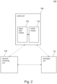
- Fig. 2 shows a schematical overview of a further embodiment of the system 110 for neuromodulation and/or neurostimulation, for the treatment of a patient, according to the present invention, with which the method according to the present invention can be performed.
- the system 110 comprises the structural and functional features as disclosed for neuromodulation system 10 in Fig. 1 .
- the system 110 is configured for treating a patient, especially for enhancing blood circulation function of a patient.
- system 110 could be configured for treating a patient, especially for enhancing any type of autonomous function of a patient.
- the system 110 comprises a control unit 116.
- control unit 116 comprises a signal input module 112 and a control module 114, cf. signal input module 12 and control module 14 as disclosed in Fig. 1 .
- the system 110 also comprises a real-time monitoring unit 118.
- the real-time monitoring unit 118 comprises a sensor.
- the senor is configured and arranged to measure and/or monitor blood pressure of a patient P.
- system 110 comprises a stimulation unit 120.
- the stimulation unit 120 is configured and arranged to provide stimulation.
- stimulation is provided by electrical stimulation.
- the stimulation unit 120 is constructed to comprise a lead.
- stimulation is provided by a lead comprising one or multiple electrodes.
- Fig. 2 Not shown in Fig. 2 is that the lead is implanted.
- Fig. 2 Not shown in Fig. 2 is that alternatively, and/or additionally, transcutaneous stimulation by a lead could generally also be possible.
- stimulation could be applied with stimulation parameters comprising at least frequency, amplitude and pulse width, wherein the frequency could be 10Hz-10kHz, the amplitude could be 0-1A or 0-15V and the pulse width could be 1-500 ⁇ s.
- the sensor is configured and arranged to measure and/or monitor blood pressure of a patient.
- control unit 116 is connected to the stimulation unit 120 and the real-time monitoring unit 118.
- connection between the control unit 116 and the stimulation unit 120 and the control unit 116 and the real-time monitoring unit 118 is a direct and bidirectional connection.
- connection between the stimulation unit 120 and the real-time monitoring unit 118 is a direct and bidirectional connection.
- the real-time monitoring unit 118 in particular the sensor of the real-time monitoring unit 180 measures blood pressure of the patient.
- a further sensor could additionally and/or alternatively measure cumulative firing rates from a brainstem control area.
- a further sensor could additionally and/or alternatively measure cumulative firing rates from the ventrolateral medulla.
- the signals indicative for blood circulation could be signals indicative for blood pressure and/or cumulative firing rates from at least one brainstem control area, especially but. Not limited to firing rates from the rostral ventrolateral medulla.
- the system 10, 110 seeks to replace this disrupted control.
- the linear relationship between blood pressure and amplitude of epidural electrical stimulation EES provides the basis for a linear proportional control mechanism.
- a patient suffering from SCI is equipped with the system 10, 110 as disclosed in Fig. 1 and/or Fig. 2 .
- Fig. 5c shows an example of closed-loop control of blood pressure according to the present invention in non-human primates
- Fig. 5d shows an example of closed-loop control of blood pressure according to the present invention in a human patient
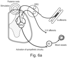
- Stimulation enters through the posterior roots of the dorsal root ganglion DRG and activates sympathetic pre-ganglionic neurons SPN, which then activate splanchic ganglia SG and blood vessels responsible for blood pressure.
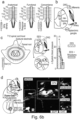
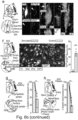
- Fig. 6b shows a schematical overview of mechanisms, by which EES stabilizes hemodynamics.
- Part a shows the intraspinal density of neurons retrogradely traced from the splanchnic ganglia, amplitude of pressor responses to TESS applied to each segment, and concordance between anatomical and functional datasets.
- Part b shows hypothetical circuits activated by TESS to elicit blood vessel constriction.
- Part c shows color-coded electrical potentials following TESS applied to the spinal cord suggesting the exclusive activation of afferent fibres.
- Part d shows trans-synaptic retrograde tracing revealing interneurons connected to splanchnic ganglia.
- Part e shows interneurons. These interneurons express the excitatory marker Slc17a6, and receive vGlut1 synapses from large-diameter proprioceptive afferents.
- Fig. 7 shows a schematical overview of a further embodiment of the system 210 for neuromodulation and/or neurostimulation, for the treatment of a patient, according to the present invention, with which the method according to the present invention can be performed.
- the system 210 is neurostimulation system 210 for treating a patient, especially for enhancing at least one autonomous function such as blood circulation and/or respiration.
- the system 210 is a neurostimulation system 210 for treating a patient, especially for enhancing blood pressure function.
- the system 210 comprises a sensing element 212.
- control module 214 is connected to the sensing element 212.
- the sensing element 212 is a sensor configured to sense a signal indicative for blood pressure of a patient.
- the sensing element 212 could be alternatively and/or additionally be configured to sense posture and/or position.
- the invasive arterial line senses blood pressure directly and in real-time.
- the sensing element 212 provides sporadic monitoring of blood pressure and/or monitoring blood pressure in preset time intervals.
- the sensing element 212 could be an implanted and/or implantable sensor and/or a non-implantable and/or non-implanted sensor.
- the sensing element 212 could be an external beat-by beat blood pressure monitor, intrathecal catheter and/or a standard brachial blood pressure cuff and/or any type of upper arm blood pressure monitor system and/or any type of wrist blood pressure monitor system and/or any type of finger blood pressure monitor system.
- system 210 could comprise at least one temporal mapping module configured to link temporal electrode stimulation configurations to at least one physiological effect.
- control module 214 identifies a target value for autonomic function based on a signal provided by the sensing element 212.
- the spatial mapping module links spatial electrode stimulation configurations Config to blood pressure, in particular systolic blood pressure SBP.
- the spatial mapping module links spatial electrode stimulation configurations Config to at least one physiological effect.
- the spatial mapping module 216 could isolate key electrodes E based on anatomical location and a learning procedure initiated at these electrodes E to optimize the configuration of the surrounding electrodes E.
- the spatial mapping module 216 could be configured to perform a reinforcement learning procedure, wherein the reinforcement learning procedure is part of the process to link spatial electrode stimulation configurations Config targeting the afferent fibers in the dorsal/posterior roots to at least one physiological effect.
- the spatial mapping module 216 could be configured to perform a spatial mapping phase for identifying a suitable electrode configuration Config in terms of selected electrodes E and their spatial arrangement in a first step and a parameter mapping phase for adjusting stimulation parameters for the stimulation provided by the selected electrodes E in the first step.
- the stimulation parameters could comprise at least frequency, amplitude and pulse width, wherein the frequency is 10Hz-10kHz, the amplitude is 0-1A or 0-15V and the pulse width is 1-500 ⁇ s.
- Fig. 7 stimulation could be applied by burst train stimulation. Pulse trains called burst train stimulation could be preferred to increase the specificity and comfort.
- Burst train stimulation could comprise a series of several pulses, e.g. 3 to 5 pulses delivered at 200Hz to 700Hz, repeated at the frequency 10-120Hz.
- system 210 The use of the system 210 and functionality of the system 210 can be described as follows:
- a neuromodulation system 210 for treating a patient, especially for enhancing at least one autonomous function such as blood circulation and/or respiration.
- a neurostimulation system 210 for treating a patient, especially for enhancing at least one autonomous function such a blood circulation and/or respiration is disclosed.
- a method is disclosed, the method characterized in that the method is performed with the system 10, 110 and 210 and as defined in the claims.
- the method could comprise the step of providing stimulation.
- stimulation parameters could comprise at least frequency, amplitude and pulse width, wherein the frequency could be 10Hz-10kHz, the amplitude could be 0-1A or 0-15V and the pulse width could be 1-500 ⁇ s.
- a patient suffering from spinal cord injury SCI was equipped with the system 210 disclosed in Fig. 7 .
- a series of spatial electrode configurations Config is shown, and the immediate blood pressure response, i.e. systolic blood pressure SBP, of the patient was measured, cf. Fig. 8a .
- the optimal spatial electrode configuration Config was selected, based on both the immediate increase in blood pressure and the absence of significant muscle contractions, cf. Fig. 8b .
- the optimal spatial electrode configuration Config selected was configuration Config 20.
- a suboptimal spatial electrode configuration Config would be e.g. spatial configuration Config 17.
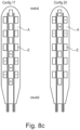
- the rostral four electrodes were identified most optimal to control blood pressure in the patient, cf. Fig. 8c .
- the system enabled the identification of this optimized parameters.
- the electrode array comprising multiple electrodes using a CT or MRI or X-Ray scan to confirm the location of the electrode array.
- Fig. 8d shows a further overview of the stimulation effect on blood pressure.
- Fig. 9 shows embodiments, where the stimulus changing blood pressure is constant or variable.
- Fig. 10 shows a blood pressure collapse, which is treated and rescued by the system according to the present invention.
Landscapes
- Health & Medical Sciences (AREA)
- Life Sciences & Earth Sciences (AREA)
- Engineering & Computer Science (AREA)
- Public Health (AREA)
- Biomedical Technology (AREA)
- Veterinary Medicine (AREA)
- Animal Behavior & Ethology (AREA)
- General Health & Medical Sciences (AREA)
- Neurology (AREA)
- Biophysics (AREA)
- Physics & Mathematics (AREA)
- Medical Informatics (AREA)
- Surgery (AREA)
- Molecular Biology (AREA)
- Heart & Thoracic Surgery (AREA)
- Pathology (AREA)
- Neurosurgery (AREA)
- Physiology (AREA)
- Orthopedic Medicine & Surgery (AREA)
- Radiology & Medical Imaging (AREA)
- Nuclear Medicine, Radiotherapy & Molecular Imaging (AREA)
- Cardiology (AREA)
- Rheumatology (AREA)
- Oral & Maxillofacial Surgery (AREA)
- Dentistry (AREA)
- Physical Education & Sports Medicine (AREA)
- Psychology (AREA)
- Computer Networks & Wireless Communication (AREA)
- Optics & Photonics (AREA)
- Measuring Pulse, Heart Rate, Blood Pressure Or Blood Flow (AREA)
- Electrotherapy Devices (AREA)
Claims (15)
- Neuromodulationssystem (10, 110) zum Bereitstellen einer epiduralen Stimulation zur Behandlung eines Patienten und zur Verbesserung mindestens einer autonomen Funktion wie Blutzirkulation und/oder Atmung, wobei das System umfasstmindestens ein Signaleingangsmodul (12, 112), das dazu konfiguriert ist, mindestens ein oder mehrere Signale zu empfangen, die auf die Blutzirkulation hinweisen,wobei das mindestens eine Signaleingangsmodul (12, 112) ferner dazu konfiguriert ist, Basisliniensignale zu empfangen, wobei die Basisliniensignale mindestens einen Zielwert definieren, undmindestens ein Steuermodul (14, 114), wobei das Steuermodul (14, 114) mit dem Signaleingangsmodul (12, 112) verbunden ist,wobei das Steuermodul (14, 114) dazu konfiguriert ist, die vom Neuromodulationssystem (10, 110) bereitgestellte epidurale elektrische Stimulation auf der Grundlage der vom Signaleingangsmodul (12, 112) empfangenen Signale anzupassen, wobei das Steuermodul (14, 114) dazu konfiguriert ist, Unterschiede zwischen dem mindestens einen Zielwert und mindestens einem oder mehreren auf die Blutzirkulation hinweisenden Signalen zu erkennen, und wobei das Steuermodul (14, 114) ferner dazu konfiguriert und angeordnet ist, die Stimulation auf der Grundlage der Unterschiede zwischen dem mindestens einen Zielwert und mindestens einem oder mehreren auf die Blutzirkulation hinweisenden Signalen anzupassen,wobei das Steuermodul (14, 114) ein lineares Proportionalsteuermodul umfasst, das dazu konfiguriert ist, einen linearen Proportionalsteuermechanismus bereitzustellen, und wobei das lineare Proportionalsteuermodul ferner dazu konfiguriert ist, zumindest eines von Amplitude und Frequenz eines Stimulationsparadigmas als Reaktion auf das zumindest eine oder die mehreren Signale, die auf die Blutzirkulation hinweisen, mit einem Koeffizienten β zu modifizieren, der die lineare Proportion steuert, mit der sich die Amplitude oder Frequenz ändert.
- Neuromodulationssystem (10, 110) nach Anspruch 1,
dadurch gekennzeichnet, dass das Neuromodulationssystem (10, 110) ferner mindestens eine Stimulationseinheit (120) und/oder mindestens eine Echtzeitüberwachungseinheit (118) umfasst, wobei die mindestens eine Echtzeitüberwachungseinheit (118) mindestens einen Sensor umfasst. - Neuromodulationssystem (10, 110) nach Anspruch 1 oder 2,
dadurch gekennzeichnet, dass die Signale, die auf die Blutzirkulation hinweisen, Signale sind, die auf die Sauerstoffsättigung und/oder den Blutdruck und/oder die kumulativen Feuerungsraten aus mindestens einem Hirnstammkontrollbereich hinweisen. - Neuromodulationssystem (10, 110) nach Anspruch 1,
dadurch gekennzeichnet, dass das mindestens eine Signaleingangsmodul (12, 112) ein Eingangsschaltmodul umfasst, wobei das Eingangsschaltmodul dazu konfiguriert ist, zwischen Signalen umzuschalten, die den Blutdruck und die kumulativen Feuerungsraten von mindestens einem Hirnstammkontrollbereich anzeigen. - Neuromodulationssystem (10, 110) nach einem der vorstehenden Ansprüche, dadurch gekennzeichnet, dass das Steuermodul (14, 114) ein Vorwärtsmodul umfasst, wobei das Vorwärtsmodul so konfiguriert und angeordnet ist, dass es mindestens einen prädiktiven Effekt der Stimulation berücksichtigt, um den Koeffizienten β innerhalb eines angegebenen Zeitfensters anzupassen.
- Neuromodulationssystem (10, 110) nach einem der vorstehenden Ansprüche, dadurch gekennzeichnet, dass das Steuermodul (14, 114) so konfiguriert ist, dass es Steuerparameter für das Stimulationsparadigma umfasst.
- Neuromodulationssystem (210) nach einem der vorstehenden Ansprüche, dadurch gekennzeichnet, dassdas Signaleingabemodul mindestens ein Sensorelement (212) ist oder umfasst, das so konfiguriert ist, dass es ein Signal erfasst, das einen physiologischen Parameter eines Patienten anzeigt, mindestens ein räumliches Abbildungsmodul (216), das so konfiguriert ist, dass es räumliche Elektrodenstimulationskonfigurationen (Config), die auf die afferenten Fasern in den dorsalen/hinteren Wurzeln abzielen, mit mindestens einem physiologischen Effekt verknüpft,mindestens ein Parameterabbildungsmodul (218), das dazu konfiguriert ist, Stimulationsparameter für das Steuermodul (214) basierend auf den vom Sensorelement (212) und/oder dem räumlichen Abbildungsmodul (216) empfangenen Eingaben vorzubereiten.
- Neuromodulationssystem (10) nach Anspruch 7,
dadurch gekennzeichnet, dass der physiologische Parameter mindestens einer der folgenden ist: Sauerstoffsättigung, Blutdruck des Patienten, Rückenmarksperfusionsdruck des Patienten, Körperhaltung des Patienten und/oder Position des Patienten. - System (10) nach Anspruch 7, dadurch gekennzeichnet, dass das System mindestens ein Stimulationselement umfasst, das mindestens ein Elektrodenarray A, umfassend mehrere Elektroden E, umfasst.
- System (10) nach Anspruch 9, dadurch gekennzeichnet, dass das System mindestens ein zeitliches Abbildungsmodul umfasst, das so konfiguriert ist, dass es zeitliche Elektrodenstimulationskonfigurationen mit mindestens einem physiologischen Effekt verknüpft.
- System (10) nach einem der Ansprüche 9 bis 10,
dadurch gekennzeichnet, dass das Steuermodul (14) dazu konfiguriert ist, einen Zielwert für die autonome Funktion basierend auf einem vom Sensorelement (12) bereitgestellten Signal zu identifizieren. - Neuromodulationssystem (10) nach einem der Ansprüche 9 bis 11, dadurch gekennzeichnet, dass das räumliche Abbildungsmodul (16) Schlüsselelektroden E auf der Grundlage der anatomischen Lage der afferenten Fasern in den dorsalen Wurzeln isoliert und an diesen Elektroden E einen Lernvorgang einleitet, um die Konfiguration der umgebenden Elektroden E zu optimieren.
- Neuromodulationssystem (10) nach einem der vorstehenden Ansprüche, dadurch gekennzeichnet, dass die Stimulationsparameter mindestens Frequenz, Amplitude und Impulsbreite umfassen, wobei die Frequenz 10 Hz bis 10 kHz, die Amplitude 0 bis 1 A oder 0 bis 15 V und die Impulsbreite 1 bis 500 µs beträgt.
- Neuromodulationssystem (10) nach einem der vorstehenden Ansprüche, dadurch gekennzeichnet, dass das räumliche Abbildungsmodul (16) so konfiguriert ist, dass es ein Verstärkungslernverfahren durchführt, wobei das Verstärkungslernverfahren Teil des Prozesses ist, um räumliche Elektrodenstimulationskonfigurationen (Config), die auf die afferenten Fasern in den dorsalen/hinteren Wurzeln abzielen, mit mindestens einem physiologischen Effekt zu verknüpfen.
- Neuromodulationssystem (10) nach einem der vorstehenden Ansprüche, dadurch gekennzeichnet, dass das räumliche Abbildungsmodul (16) dazu konfiguriert ist, in einem ersten Schritt eine räumlichen Abbildungsphase zum Identifizieren einer geeigneten Elektrodenkonfiguration (Config) hinsichtlich ausgewählter Elektroden E und ihrer räumlichen Anordnung und in dem ersten Schritt eine Parameterabbildungsphase zum Anpassen der Stimulationsparameter für die von den ausgewählten Elektroden E bereitgestellte Stimulation durchzuführen.
Applications Claiming Priority (3)
| Application Number | Priority Date | Filing Date | Title |
|---|---|---|---|
| EP19174566 | 2019-05-15 | ||
| EP19174558 | 2019-05-15 | ||
| PCT/EP2020/063563 WO2020229645A1 (en) | 2019-05-15 | 2020-05-14 | System for closed loop control of autonomic function |
Publications (2)
| Publication Number | Publication Date |
|---|---|
| EP3969103A1 EP3969103A1 (de) | 2022-03-23 |
| EP3969103B1 true EP3969103B1 (de) | 2025-07-02 |
Family
ID=70738573
Family Applications (1)
| Application Number | Title | Priority Date | Filing Date |
|---|---|---|---|
| EP20726108.2A Active EP3969103B1 (de) | 2019-05-15 | 2020-05-14 | System zur steuerung mit geschlossenem regelkreis einer autonomen funktion |
Country Status (5)
| Country | Link |
|---|---|
| US (1) | US20220125374A1 (de) |
| EP (1) | EP3969103B1 (de) |
| CN (1) | CN114390934B (de) |
| ES (1) | ES3047091T3 (de) |
| WO (1) | WO2020229645A1 (de) |
Families Citing this family (6)
| Publication number | Priority date | Publication date | Assignee | Title |
|---|---|---|---|---|
| US12357828B2 (en) | 2017-12-05 | 2025-07-15 | Ecole Polytechnique Federale De Lausanne (Epfl) | System for planning and/or providing neuromodulation |
| EP3824948A1 (de) | 2019-11-19 | 2021-05-26 | ONWARD Medical B.V. | Planungs- und/oder steuersystem für ein neuromodulationssystem |
| DE19211738T1 (de) | 2019-11-27 | 2021-09-09 | Onward Medical B.V. | Neuromodulationssystem |
| US12623080B2 (en) | 2023-06-21 | 2026-05-12 | Onward Medical N.V. | Neuromodulation system |
| CN118634132B (zh) * | 2024-05-23 | 2026-02-17 | 中国科学院深圳先进技术研究院 | 用于激发或增强人体血流动力学指标节律性振荡的系统 |
| CN119701205B (zh) * | 2025-02-25 | 2025-06-20 | 首都医科大学附属北京天坛医院 | 一种用于治疗体位性低血压的深部脑刺激系统 |
Family Cites Families (20)
| Publication number | Priority date | Publication date | Assignee | Title |
|---|---|---|---|---|
| SE346468B (de) | 1969-02-24 | 1972-07-10 | Lkb Medical Ab | |
| US5861009A (en) * | 1997-10-21 | 1999-01-19 | Sulzer Intermedics, Inc. | Implantable cardiac stimulator with rate-adaptive T-wave detection |
| US6058331A (en) | 1998-04-27 | 2000-05-02 | Medtronic, Inc. | Apparatus and method for treating peripheral vascular disease and organ ischemia by electrical stimulation with closed loop feedback control |
| US20070027495A1 (en) | 2005-07-29 | 2007-02-01 | Medtronic, Inc. | External bladder sensor for sensing bladder condition |
| US20070156200A1 (en) | 2005-12-29 | 2007-07-05 | Lilian Kornet | System and method for regulating blood pressure and electrolyte balance |
| US8457734B2 (en) * | 2006-08-29 | 2013-06-04 | Cardiac Pacemakers, Inc. | System and method for neural stimulation |
| US7797041B2 (en) | 2006-10-11 | 2010-09-14 | Cardiac Pacemakers, Inc. | Transcutaneous neurostimulator for modulating cardiovascular function |
| WO2008121703A1 (en) * | 2007-03-28 | 2008-10-09 | University Of Florida Research Foundation, Inc. | Variational parameter neurostimulation paradigm for treatment of neurologic disease |
| US20110202107A1 (en) | 2007-10-15 | 2011-08-18 | Kyushu University, National University Corporation | Blood pressure stabilization system using transdermal stimulation |
| EP2419171B1 (de) * | 2009-04-13 | 2017-11-01 | Research Foundation Of The City University Of New York | Modelle für neurokranielle elektrostimulation |
| KR101004001B1 (ko) * | 2010-05-17 | 2010-12-31 | 박종은 | 신경기능 검사장치 |
| US20130289650A1 (en) | 2012-04-25 | 2013-10-31 | Pacesetter, Inc. | Neuromodulation for Hypertension Control |
| US10413730B2 (en) * | 2013-03-15 | 2019-09-17 | Cirtec Medical Corp. | Implantable pulse generator that generates spinal cord stimulation signals for a human body |
| EP2868343A1 (de) * | 2013-10-31 | 2015-05-06 | Ecole Polytechnique Federale De Lausanne (EPFL) EPFL-TTO | System zur Bereitstellung von adaptiver elektrischer Rückenmarksstimulation zur Ermöglichung und Wiederherstellung der Bewegung nach einer neuromotorischen Störung |
| US10556107B2 (en) * | 2013-11-27 | 2020-02-11 | Ebt Medical, Inc. | Systems, methods and kits for peripheral nerve stimulation |
| WO2017053504A1 (en) * | 2015-09-22 | 2017-03-30 | Cardiac Pacemakers, Inc. | Systems and methods for monitoring autonomic health |
| US12233265B2 (en) * | 2016-08-25 | 2025-02-25 | Cala Health, Inc. | Systems and methods for treating cardiac dysfunction through peripheral nerve stimulation |
| WO2018148844A1 (en) * | 2017-02-17 | 2018-08-23 | The University Of British Columbia | Apparatus and methods for maintaining physiological functions |
| EP4252653B1 (de) * | 2017-03-28 | 2026-05-06 | Ecole Polytechnique Fédérale de Lausanne (EPFL) EPFL-TTO | Neurostimulationssystem zur zentralnervenstimulation (zns) und peripheren nervenstimulation (pns) |
| AU2018300009B2 (en) * | 2017-07-11 | 2024-03-28 | The General Hospital Corporation | Systems and methods for respiratory-gated nerve stimulation |
-
2020
- 2020-05-14 US US17/595,384 patent/US20220125374A1/en active Pending
- 2020-05-14 CN CN202080035902.2A patent/CN114390934B/zh active Active
- 2020-05-14 EP EP20726108.2A patent/EP3969103B1/de active Active
- 2020-05-14 WO PCT/EP2020/063563 patent/WO2020229645A1/en not_active Ceased
- 2020-05-14 ES ES20726108T patent/ES3047091T3/es active Active
Also Published As
| Publication number | Publication date |
|---|---|
| WO2020229645A1 (en) | 2020-11-19 |
| CN114390934A (zh) | 2022-04-22 |
| US20220125374A1 (en) | 2022-04-28 |
| CN114390934B (zh) | 2025-10-31 |
| EP3969103A1 (de) | 2022-03-23 |
| ES3047091T3 (en) | 2025-12-03 |
Similar Documents
| Publication | Publication Date | Title |
|---|---|---|
| US20220125374A1 (en) | System and method for closed loop control of autonomic function | |
| US11883664B2 (en) | Systems and methods for closed-loop pain management | |
| US12268878B2 (en) | Apparatus and methods for maintaining physiological functions | |
| US8386045B2 (en) | Systems and methods for selectively stimulating nerve roots | |
| US9259568B2 (en) | Systems and methods for delivering electric current for spinal cord stimulation | |
| US20080009916A1 (en) | Applications of heart rate variability analysis in electrotherapy affecting autonomic nervous system response | |
| EP4245358B1 (de) | System zur steuerung einer autonomen funktion | |
| US12023500B2 (en) | Contingent cardio-protection for epilepsy patients | |
| US20210370066A1 (en) | Neuromodulation and/or neurostimulation system | |
| US20250339689A1 (en) | Contingent cardio-protection for epilepsy patients | |
| US20240399151A1 (en) | Contingent Cardio-Protection For Epilepsy Patients |
Legal Events
| Date | Code | Title | Description |
|---|---|---|---|
| STAA | Information on the status of an ep patent application or granted ep patent |
Free format text: STATUS: UNKNOWN |
|
| STAA | Information on the status of an ep patent application or granted ep patent |
Free format text: STATUS: THE INTERNATIONAL PUBLICATION HAS BEEN MADE |
|
| PUAI | Public reference made under article 153(3) epc to a published international application that has entered the european phase |
Free format text: ORIGINAL CODE: 0009012 |
|
| STAA | Information on the status of an ep patent application or granted ep patent |
Free format text: STATUS: REQUEST FOR EXAMINATION WAS MADE |
|
| 17P | Request for examination filed |
Effective date: 20211215 |
|
| AK | Designated contracting states |
Kind code of ref document: A1 Designated state(s): AL AT BE BG CH CY CZ DE DK EE ES FI FR GB GR HR HU IE IS IT LI LT LU LV MC MK MT NL NO PL PT RO RS SE SI SK SM TR |
|
| DAV | Request for validation of the european patent (deleted) | ||
| DAX | Request for extension of the european patent (deleted) | ||
| STAA | Information on the status of an ep patent application or granted ep patent |
Free format text: STATUS: EXAMINATION IS IN PROGRESS |
|
| 17Q | First examination report despatched |
Effective date: 20240320 |
|
| GRAP | Despatch of communication of intention to grant a patent |
Free format text: ORIGINAL CODE: EPIDOSNIGR1 |
|
| STAA | Information on the status of an ep patent application or granted ep patent |
Free format text: STATUS: GRANT OF PATENT IS INTENDED |
|
| INTG | Intention to grant announced |
Effective date: 20250127 |
|
| RIC1 | Information provided on ipc code assigned before grant |
Ipc: A61B 5/026 20060101ALI20250117BHEP Ipc: A61B 5/021 20060101ALI20250117BHEP Ipc: A61N 1/36 20060101AFI20250117BHEP |
|
| GRAS | Grant fee paid |
Free format text: ORIGINAL CODE: EPIDOSNIGR3 |
|
| GRAA | (expected) grant |
Free format text: ORIGINAL CODE: 0009210 |
|
| STAA | Information on the status of an ep patent application or granted ep patent |
Free format text: STATUS: THE PATENT HAS BEEN GRANTED |
|
| AK | Designated contracting states |
Kind code of ref document: B1 Designated state(s): AL AT BE BG CH CY CZ DE DK EE ES FI FR GB GR HR HU IE IS IT LI LT LU LV MC MK MT NL NO PL PT RO RS SE SI SK SM TR |
|
| REG | Reference to a national code |
Ref country code: GB Ref legal event code: FG4D |
|
| REG | Reference to a national code |
Ref country code: CH Ref legal event code: EP |
|
| REG | Reference to a national code |
Ref country code: DE Ref legal event code: R096 Ref document number: 602020053775 Country of ref document: DE |
|
| REG | Reference to a national code |
Ref country code: IE Ref legal event code: FG4D |
|
| REG | Reference to a national code |
Ref country code: NL Ref legal event code: FP |
|
| REG | Reference to a national code |
Ref country code: ES Ref legal event code: FG2A Ref document number: 3047091 Country of ref document: ES Kind code of ref document: T3 Effective date: 20251203 |
|
| PG25 | Lapsed in a contracting state [announced via postgrant information from national office to epo] |
Ref country code: PT Free format text: LAPSE BECAUSE OF FAILURE TO SUBMIT A TRANSLATION OF THE DESCRIPTION OR TO PAY THE FEE WITHIN THE PRESCRIBED TIME-LIMIT Effective date: 20251103 |
|
| REG | Reference to a national code |
Ref country code: AT Ref legal event code: MK05 Ref document number: 1808593 Country of ref document: AT Kind code of ref document: T Effective date: 20250702 |
|
| PG25 | Lapsed in a contracting state [announced via postgrant information from national office to epo] |
Ref country code: IS Free format text: LAPSE BECAUSE OF FAILURE TO SUBMIT A TRANSLATION OF THE DESCRIPTION OR TO PAY THE FEE WITHIN THE PRESCRIBED TIME-LIMIT Effective date: 20251102 |
|
| PG25 | Lapsed in a contracting state [announced via postgrant information from national office to epo] |
Ref country code: NO Free format text: LAPSE BECAUSE OF FAILURE TO SUBMIT A TRANSLATION OF THE DESCRIPTION OR TO PAY THE FEE WITHIN THE PRESCRIBED TIME-LIMIT Effective date: 20251002 |
|
| REG | Reference to a national code |
Ref country code: LT Ref legal event code: MG9D |
|
| PG25 | Lapsed in a contracting state [announced via postgrant information from national office to epo] |
Ref country code: AT Free format text: LAPSE BECAUSE OF FAILURE TO SUBMIT A TRANSLATION OF THE DESCRIPTION OR TO PAY THE FEE WITHIN THE PRESCRIBED TIME-LIMIT Effective date: 20250702 |
|
| PG25 | Lapsed in a contracting state [announced via postgrant information from national office to epo] |
Ref country code: FI Free format text: LAPSE BECAUSE OF FAILURE TO SUBMIT A TRANSLATION OF THE DESCRIPTION OR TO PAY THE FEE WITHIN THE PRESCRIBED TIME-LIMIT Effective date: 20250702 |
|
| PG25 | Lapsed in a contracting state [announced via postgrant information from national office to epo] |
Ref country code: HR Free format text: LAPSE BECAUSE OF FAILURE TO SUBMIT A TRANSLATION OF THE DESCRIPTION OR TO PAY THE FEE WITHIN THE PRESCRIBED TIME-LIMIT Effective date: 20250702 |
|
| PG25 | Lapsed in a contracting state [announced via postgrant information from national office to epo] |
Ref country code: GR Free format text: LAPSE BECAUSE OF FAILURE TO SUBMIT A TRANSLATION OF THE DESCRIPTION OR TO PAY THE FEE WITHIN THE PRESCRIBED TIME-LIMIT Effective date: 20251003 |
|
| PG25 | Lapsed in a contracting state [announced via postgrant information from national office to epo] |
Ref country code: SE Free format text: LAPSE BECAUSE OF FAILURE TO SUBMIT A TRANSLATION OF THE DESCRIPTION OR TO PAY THE FEE WITHIN THE PRESCRIBED TIME-LIMIT Effective date: 20250702 Ref country code: CZ Free format text: LAPSE BECAUSE OF FAILURE TO SUBMIT A TRANSLATION OF THE DESCRIPTION OR TO PAY THE FEE WITHIN THE PRESCRIBED TIME-LIMIT Effective date: 20250702 |
|
| PG25 | Lapsed in a contracting state [announced via postgrant information from national office to epo] |
Ref country code: LV Free format text: LAPSE BECAUSE OF FAILURE TO SUBMIT A TRANSLATION OF THE DESCRIPTION OR TO PAY THE FEE WITHIN THE PRESCRIBED TIME-LIMIT Effective date: 20250702 |
|
| PG25 | Lapsed in a contracting state [announced via postgrant information from national office to epo] |
Ref country code: BG Free format text: LAPSE BECAUSE OF FAILURE TO SUBMIT A TRANSLATION OF THE DESCRIPTION OR TO PAY THE FEE WITHIN THE PRESCRIBED TIME-LIMIT Effective date: 20250702 Ref country code: PL Free format text: LAPSE BECAUSE OF FAILURE TO SUBMIT A TRANSLATION OF THE DESCRIPTION OR TO PAY THE FEE WITHIN THE PRESCRIBED TIME-LIMIT Effective date: 20250702 |
|
| PG25 | Lapsed in a contracting state [announced via postgrant information from national office to epo] |
Ref country code: RS Free format text: LAPSE BECAUSE OF FAILURE TO SUBMIT A TRANSLATION OF THE DESCRIPTION OR TO PAY THE FEE WITHIN THE PRESCRIBED TIME-LIMIT Effective date: 20251002 |
|
| PG25 | Lapsed in a contracting state [announced via postgrant information from national office to epo] |
Ref country code: SM Free format text: LAPSE BECAUSE OF FAILURE TO SUBMIT A TRANSLATION OF THE DESCRIPTION OR TO PAY THE FEE WITHIN THE PRESCRIBED TIME-LIMIT Effective date: 20250702 |
|
| PG25 | Lapsed in a contracting state [announced via postgrant information from national office to epo] |
Ref country code: DK Free format text: LAPSE BECAUSE OF FAILURE TO SUBMIT A TRANSLATION OF THE DESCRIPTION OR TO PAY THE FEE WITHIN THE PRESCRIBED TIME-LIMIT Effective date: 20250702 |
|
| PG25 | Lapsed in a contracting state [announced via postgrant information from national office to epo] |
Ref country code: EE Free format text: LAPSE BECAUSE OF FAILURE TO SUBMIT A TRANSLATION OF THE DESCRIPTION OR TO PAY THE FEE WITHIN THE PRESCRIBED TIME-LIMIT Effective date: 20250702 Ref country code: SK Free format text: LAPSE BECAUSE OF FAILURE TO SUBMIT A TRANSLATION OF THE DESCRIPTION OR TO PAY THE FEE WITHIN THE PRESCRIBED TIME-LIMIT Effective date: 20250702 |
|
| PLBE | No opposition filed within time limit |
Free format text: ORIGINAL CODE: 0009261 |
|
| STAA | Information on the status of an ep patent application or granted ep patent |
Free format text: STATUS: NO OPPOSITION FILED WITHIN TIME LIMIT |