EP3968734A1 - Light source device, and sterilizing/deodorizing device - Google Patents
Light source device, and sterilizing/deodorizing device Download PDFInfo
- Publication number
- EP3968734A1 EP3968734A1 EP21195880.6A EP21195880A EP3968734A1 EP 3968734 A1 EP3968734 A1 EP 3968734A1 EP 21195880 A EP21195880 A EP 21195880A EP 3968734 A1 EP3968734 A1 EP 3968734A1
- Authority
- EP
- European Patent Office
- Prior art keywords
- excimer lamp
- switching element
- time
- light
- lighting
- Prior art date
- Legal status (The legal status is an assumption and is not a legal conclusion. Google has not performed a legal analysis and makes no representation as to the accuracy of the status listed.)
- Granted
Links
Images


Classifications
-
- H—ELECTRICITY
- H05—ELECTRIC TECHNIQUES NOT OTHERWISE PROVIDED FOR
- H05B—ELECTRIC HEATING; ELECTRIC LIGHT SOURCES NOT OTHERWISE PROVIDED FOR; CIRCUIT ARRANGEMENTS FOR ELECTRIC LIGHT SOURCES, IN GENERAL
- H05B41/00—Circuit arrangements or apparatus for igniting or operating discharge lamps
- H05B41/02—Details
- H05B41/04—Starting switches
-
- A—HUMAN NECESSITIES
- A61—MEDICAL OR VETERINARY SCIENCE; HYGIENE
- A61L—METHODS OR APPARATUS FOR STERILISING MATERIALS OR OBJECTS IN GENERAL; DISINFECTION, STERILISATION OR DEODORISATION OF AIR; CHEMICAL ASPECTS OF BANDAGES, DRESSINGS, ABSORBENT PADS OR SURGICAL ARTICLES; MATERIALS FOR BANDAGES, DRESSINGS, ABSORBENT PADS OR SURGICAL ARTICLES
- A61L2/00—Disinfection or sterilisation of materials or objects, in general; Accessories therefor
- A61L2/02—Disinfection or sterilisation of materials or objects, in general; Accessories therefor using physical processes
- A61L2/08—Radiation
- A61L2/10—Ultraviolet [UV] radiation
-
- A—HUMAN NECESSITIES
- A61—MEDICAL OR VETERINARY SCIENCE; HYGIENE
- A61L—METHODS OR APPARATUS FOR STERILISING MATERIALS OR OBJECTS IN GENERAL; DISINFECTION, STERILISATION OR DEODORISATION OF AIR; CHEMICAL ASPECTS OF BANDAGES, DRESSINGS, ABSORBENT PADS OR SURGICAL ARTICLES; MATERIALS FOR BANDAGES, DRESSINGS, ABSORBENT PADS OR SURGICAL ARTICLES
- A61L2/00—Disinfection or sterilisation of materials or objects, in general; Accessories therefor
- A61L2/24—Apparatus using programmed or automatic operation
-
- A—HUMAN NECESSITIES
- A61—MEDICAL OR VETERINARY SCIENCE; HYGIENE
- A61L—METHODS OR APPARATUS FOR STERILISING MATERIALS OR OBJECTS IN GENERAL; DISINFECTION, STERILISATION OR DEODORISATION OF AIR; CHEMICAL ASPECTS OF BANDAGES, DRESSINGS, ABSORBENT PADS OR SURGICAL ARTICLES; MATERIALS FOR BANDAGES, DRESSINGS, ABSORBENT PADS OR SURGICAL ARTICLES
- A61L9/00—Disinfection, sterilisation or deodorisation of air
- A61L9/16—Disinfection, sterilisation or deodorisation of air using physical phenomena
- A61L9/18—Radiation
- A61L9/20—Ultraviolet radiation
-
- H—ELECTRICITY
- H05—ELECTRIC TECHNIQUES NOT OTHERWISE PROVIDED FOR
- H05B—ELECTRIC HEATING; ELECTRIC LIGHT SOURCES NOT OTHERWISE PROVIDED FOR; CIRCUIT ARRANGEMENTS FOR ELECTRIC LIGHT SOURCES, IN GENERAL
- H05B41/00—Circuit arrangements or apparatus for igniting or operating discharge lamps
- H05B41/14—Circuit arrangements
- H05B41/26—Circuit arrangements in which the lamp is fed by power derived from DC by means of a converter, e.g. by high-voltage DC
- H05B41/28—Circuit arrangements in which the lamp is fed by power derived from DC by means of a converter, e.g. by high-voltage DC using static converters
-
- H—ELECTRICITY
- H05—ELECTRIC TECHNIQUES NOT OTHERWISE PROVIDED FOR
- H05B—ELECTRIC HEATING; ELECTRIC LIGHT SOURCES NOT OTHERWISE PROVIDED FOR; CIRCUIT ARRANGEMENTS FOR ELECTRIC LIGHT SOURCES, IN GENERAL
- H05B41/00—Circuit arrangements or apparatus for igniting or operating discharge lamps
- H05B41/14—Circuit arrangements
- H05B41/26—Circuit arrangements in which the lamp is fed by power derived from DC by means of a converter, e.g. by high-voltage DC
- H05B41/28—Circuit arrangements in which the lamp is fed by power derived from DC by means of a converter, e.g. by high-voltage DC using static converters
- H05B41/2806—Circuit arrangements in which the lamp is fed by power derived from DC by means of a converter, e.g. by high-voltage DC using static converters with semiconductor devices and specially adapted for lamps without electrodes in the vessel, e.g. surface discharge lamps, electrodeless discharge lamps
-
- H—ELECTRICITY
- H05—ELECTRIC TECHNIQUES NOT OTHERWISE PROVIDED FOR
- H05B—ELECTRIC HEATING; ELECTRIC LIGHT SOURCES NOT OTHERWISE PROVIDED FOR; CIRCUIT ARRANGEMENTS FOR ELECTRIC LIGHT SOURCES, IN GENERAL
- H05B41/00—Circuit arrangements or apparatus for igniting or operating discharge lamps
- H05B41/14—Circuit arrangements
- H05B41/36—Controlling
- H05B41/38—Controlling the intensity of light
-
- H—ELECTRICITY
- H05—ELECTRIC TECHNIQUES NOT OTHERWISE PROVIDED FOR
- H05B—ELECTRIC HEATING; ELECTRIC LIGHT SOURCES NOT OTHERWISE PROVIDED FOR; CIRCUIT ARRANGEMENTS FOR ELECTRIC LIGHT SOURCES, IN GENERAL
- H05B41/00—Circuit arrangements or apparatus for igniting or operating discharge lamps
- H05B41/14—Circuit arrangements
- H05B41/36—Controlling
- H05B41/38—Controlling the intensity of light
- H05B41/382—Controlling the intensity of light during the transitional start-up phase
-
- A—HUMAN NECESSITIES
- A61—MEDICAL OR VETERINARY SCIENCE; HYGIENE
- A61L—METHODS OR APPARATUS FOR STERILISING MATERIALS OR OBJECTS IN GENERAL; DISINFECTION, STERILISATION OR DEODORISATION OF AIR; CHEMICAL ASPECTS OF BANDAGES, DRESSINGS, ABSORBENT PADS OR SURGICAL ARTICLES; MATERIALS FOR BANDAGES, DRESSINGS, ABSORBENT PADS OR SURGICAL ARTICLES
- A61L2202/00—Aspects relating to methods or apparatus for disinfecting or sterilising materials or objects
- A61L2202/10—Apparatus features
- A61L2202/11—Apparatus for generating biocidal substances, e.g. vaporisers, UV lamps
-
- A—HUMAN NECESSITIES
- A61—MEDICAL OR VETERINARY SCIENCE; HYGIENE
- A61L—METHODS OR APPARATUS FOR STERILISING MATERIALS OR OBJECTS IN GENERAL; DISINFECTION, STERILISATION OR DEODORISATION OF AIR; CHEMICAL ASPECTS OF BANDAGES, DRESSINGS, ABSORBENT PADS OR SURGICAL ARTICLES; MATERIALS FOR BANDAGES, DRESSINGS, ABSORBENT PADS OR SURGICAL ARTICLES
- A61L2202/00—Aspects relating to methods or apparatus for disinfecting or sterilising materials or objects
- A61L2202/10—Apparatus features
- A61L2202/14—Means for controlling sterilisation processes, data processing, presentation and storage means, e.g. sensors, controllers, programs
-
- Y—GENERAL TAGGING OF NEW TECHNOLOGICAL DEVELOPMENTS; GENERAL TAGGING OF CROSS-SECTIONAL TECHNOLOGIES SPANNING OVER SEVERAL SECTIONS OF THE IPC; TECHNICAL SUBJECTS COVERED BY FORMER USPC CROSS-REFERENCE ART COLLECTIONS [XRACs] AND DIGESTS
- Y02—TECHNOLOGIES OR APPLICATIONS FOR MITIGATION OR ADAPTATION AGAINST CLIMATE CHANGE
- Y02B—CLIMATE CHANGE MITIGATION TECHNOLOGIES RELATED TO BUILDINGS, e.g. HOUSING, HOUSE APPLIANCES OR RELATED END-USER APPLICATIONS
- Y02B20/00—Energy efficient lighting technologies, e.g. halogen lamps or gas discharge lamps
Definitions
- the present invention relates to a light source device.
- the present invention relates to a light source device including an excimer lamp that emits ultraviolet light by dielectric-barrier discharge and a lighting device of the excimer lamp.
- Patent Document 1 JP 6717335 B2
- an object of the present invention is to provide a new light source device using an excimer lamp, particularly a light source device for sterilization/deodorization.
- a light source device includes an excimer lamp that emits ultraviolet light by dielectric-barrier discharge and a flyback-type lighting device that supplies power to the excimer lamp.
- the lighting device includes a switching element, a transformer to which the switching element is connected on the primary side and the excimer lamp is connected on the secondary side, and a control circuit that supplies a drive signal to the switching element.
- the control circuit controls the switching element on and off so that the switching frequency (FS) (ON-timing frequency) for the switching element at the time of starting to light the excimer lamp is lower than the switching frequency (FO) for the switching element at the time of steady-state lighting of the excimer lamp, and the ON-duty (TS) for the switching element at the time of starting to light the excimer lamp is lower than the ON-duty (TO) for the switching element at the time of steady-state lighting of the excimer lamp.
- FS switching frequency
- FO switching frequency
- TS ON-duty
- control circuit may control the switching element on and off so that the switching frequency (FS) at the time of starting to light the excimer lamp increases stepwise toward the switching frequency (FO) at the time of steady-state lighting of the excimer lamp.
- control circuit may control the switching elements on and off so that the ON-duty (TS) at the time of starting to light the excimer lamp increases stepwise toward the ON-duty (TO) at the time of steady-state lighting of the excimer lamp.
- TS ON-duty
- TO ON-duty
- the excimer lamp may include a light-emitting tube with a substantial rod shape and a pair of electrodes arranged in a ring shape at both ends of the light-emitting tube.
- the excimer lamp may emit ultraviolet light having a wavelength of 172 nm.
- the excimer lamp may comprise a light-emitting tube with a total length of 10 cm or less, and be a sterilizing/deodorizing lamp used in an enclosed space.
- a sterilizing/deodorizing device includes an excimer lamp that emits ultraviolet light by dielectric-barrier discharge; a flyback-type lighting device that supplies power to the excimer lamp; and a control circuit equipped with the lighting device, including a switching element and a transformer to which the switching element is connected on the primary side and the excimer lamp is connected on the secondary side, and which supplies a drive signal to the switching element.
- the control circuit controls the switching element on and off so that the switching frequency (FS) (ON-timing frequency) for the switching element at the time of starting to light the excimer lamp is lower than the switching frequency (FO) for the switching element at the time of steady-state lighting of the excimer lamp, and the ON-duty (TS) for the switching element at the time of starting to light the excimer lamp is lower than the ON-duty (TO) for the switching element at the time of steady-state lighting of the excimer lamp.
- FS switching frequency
- FO switching frequency
- TS ON-duty
- the light source device of the present invention can reliably light the excimer lamp at the time of starting to light, by controlling it differently from the time of steady lighting.
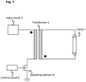
- Fig. 1 illustrates an overall configuration of a light source device according to the present invention.
- the light source device shown in Fig. 1 is equipped with an excimer lamp 1, a transformer 2, an input circuit 3, a switching element 4, and a control circuit 5.
- the excimer lamp 1 (hereinafter referred to simply as "lamp 1") is equipped with a pair of electrodes, both of which are electrically connected to a secondary winding of the transformer 2.
- the input circuit 3 to which power is supplied from a commercial power supply or a DC power supply is connected to one end of a primary winding of the transformer 2.
- the switching element 4 such as a field-effect transistor (FET) element is connected to the other end of the primary winding of the transformer 2, and a control circuit 5 is connected to a gate of the switching element 4.
- This circuit shown in Fig. 1 is generally called a boost flyback circuit, where a one-pulse voltage waveform is periodically and repeatedly generated on the secondary side of the transformer 2 corresponding to an OFF timing of the switching element 4.
- Figs. 2A and 2B illustrate enlarged views of the lamp 1 according to the present invention.
- Fig. 2A illustrates an external view of the lamp 1
- Fig. 2B illustrates an internal structure of the lamp 1.
- the lamp 1 includes a light-emitting tube 11 with a substantial rod shape as a whole, and a pair of electrodes 12 and 13 are provided at both ends thereof.
- the light-emitting tube 11 is made of quartz glass which is a dielectric material, and xenon gas is sealed therein as a discharge gas. When a voltage is applied to both electrodes, an electrical discharge occurs inside the light-emitting tube 11 as shown in Fig. 2B .
- a platinum paste is applied to the inner surface of the light-emitting tube 11 as a start-up auxiliary function member at the position corresponding to the electrode 12.
- Fig. 2B schematically illustrates the situation where discharge is occurring in the light-emitting tube 11 with thin hatched notation.
- the electrode form of the pair of electrodes 12 and 13 is not limited to the structure shown in Figs. 2A and 2A .
- a pair of electrodes with a long strip may be arranged on the outer surface of the light-emitting tube, extending in the longitudinal direction (for example, JP 2009-123406 A ), or only one electrode may be arranged inside the light-emitting tube (for example, JP 2002-319371 A ).
- the lamp 1 is a lamp that emits UVC light (wavelength of 200 to 280 nm) or vacuum-ultraviolet light (wavelength of 200 nm or less).
- the lamp 1 according to the present invention is also expected to be mounted on a vehicle or a lighting fixture, in which case the rod-shaped light-emitting tube is relatively short.
- the light-emitting tube 11 has a total length of 40 mm and a diameter ⁇ of 6 mm.
- Fig. 3 illustrates a voltage waveform generated on the secondary side of the transformer 2 in the light source device according to the present invention.
- the flyback circuit shown in Fig. 1 supplies a voltage waveform with a substantially single peak to the lamp 1, as shown in Fig. 3 .
- the oscillation current after the peak hardly occurs in relation to a regenerative current of the FET element (the switching element 4).
- a conventional excimer lamp is generally large, with a total length of 100 mm or more, and in order to favorably generate a discharge between the electrodes, relatively high voltage sinusoidal or square wave pulses are supplied to the excimer lamp.
- the light source device according to the present invention is supposed to be mounted on a vehicle or a lighting fixture as one of its applications, in which case the overall scale of the light source device is smaller.
- the lamp 1 shown in each of Figs. 2A and 2B is comparatively small, with a total length of less than 100 mm, which means that a flyback-type lighting circuit suitable for low power and high voltage can be adopted. If the flyback method is adopted for an excimer lamp that requires high power, the transformer of the lighting device will be huge and the switching element will need to be able to withstand high current and high voltage, which is not realistic.
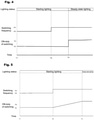
- Fig. 4 illustrates a time chart for explaining control contents for stably lighting the lamp 1 according to the present invention.
- the excimer lamp is turned on.
- the lamp 1 is in a starting lighting state, and after time T3, it is in a steady lighting state.
- a switching frequency (FS) from time T2 to time T3 is set to a lower value than a switching frequency (FO) during steady-state lighting.
- the switching frequency corresponds to a frequency of a signal from the control circuit 5 to the switching element 4 in Fig. 1 , but can also be said to be a cycle of a current waveform supplied to the lamp in Fig. 3 .
- the switching frequency may also be described as the ON-timing frequency.
- an ON-duty (TS) of switching from time T1 to time T3 is set to a lower value than an ON-duty (TO) during steady-state lighting.
- the reason for this is to keep the lamp power almost the same during steady-state lighting as well as during starting lighting.
- the lighting frequency is lowered and the voltage supplied to the lamp 1 is increased to ensure stable lighting.
- the ON-duty of the switching element 4 is lowered because the amount of ozone generated increases with the increase in the amount of ultraviolet light.
- a numerical example is as follows.
- the lamp voltage during steady-state lighting is 3.8 kV, while the lamp voltage during starting lighting is 4.5 kV.
- the switching frequency (FO) during steady-state lighting is 28 kHz while the switching frequency (FS) during starting lighting is 24 kHz.
- the ON-duty (TO) of the switching element 4 during steady-state lighting is 80%, while the ON-duty (TS) of the switching element 4 during starting lighting is 53%.
- the timing (elapsed time from time T1 to time T2) for switching the switching frequency from the value at starting lighting (FS) to the value at the steady-state lighting (FO) is 10 ms
- the timing (elapsed time from time T1 to time T3) for switching the ON-duty of the switching element 4 from the value at starting lighting (TS) to the value at the steady-state lighting (TO) is 18 ms.
- the light source device As described above, although the light source device according to the present invention is downsized, lighting can be stably started and the problem of generating a large amount of ozone due to the increase in the amount of ultraviolet light when starting to light the lamp 1 can be avoided.
- Fig. 5 is a modification of Fig. 4 and illustrates a time chart for explaining control contents for stably lighting the excimer lamp according to the present invention.
- the excimer lamp is turned on. From time T1 to time T3, the lamp 1 is in the starting lighting state, and after time T3, it is in the steady lighting state.
- the difference between the control shown in Fig. 5 and the control shown in Fig. 4 is that the ON-duty of the switching element 4 is controlled to increase gradually at the timing (T2) when the switching frequency is switched from the setting value (FS) during lighting starting to the setting value (FO) during steady-state lighting.
- the amount of change in the ultraviolet light during the transition of the lamp 1 from the starting lighting state to the steady lighting state can be reduced.
- Fig. 6 is a further modification of Figs. 4 and 5 and illustrates a time chart for explaining control contents for stably lighting the lamp 1 according to the present invention.
- the excimer lamp is turned on. From time T1 to time T3, the lamp 1 is in the starting lighting state, and after time T3, it is in the steady lighting state.
- the difference between the control shown in Fig. 6 and the control shown in Fig. 4 is that the ON-duty of the switching element 4 is controlled to increase stepwise at the timing (T2) when the switching frequency is switched from the setting value (FS) during lighting starting to the setting value (FO) during steady-state lighting.
- the numerical example shows that the ON-duty of switching element 4 at time T2 is 53%, and the ON-duty is increased in steps of 56% ⁇ 59% ⁇ 62% ⁇ 65% ⁇ 68% ⁇ 71% ⁇ 74% ⁇ 77% ⁇ 80% every 1 millisecond until the ON-duty at steady-state lighting of 80% is reached over 9 milliseconds.
- the lamp 1 can be stably transitioned from the starting lighting state to the steady lighting state.
Landscapes
- Health & Medical Sciences (AREA)
- Epidemiology (AREA)
- Life Sciences & Earth Sciences (AREA)
- Animal Behavior & Ethology (AREA)
- General Health & Medical Sciences (AREA)
- Public Health (AREA)
- Veterinary Medicine (AREA)
- Circuit Arrangements For Discharge Lamps (AREA)
- Disinfection, Sterilisation Or Deodorisation Of Air (AREA)
Abstract
Description
- The present invention relates to a light source device. In particular, the present invention relates to a light source device including an excimer lamp that emits ultraviolet light by dielectric-barrier discharge and a lighting device of the excimer lamp.
- In recent years, a sterilizing/deodorizing device using an excimer lamp that emits ultraviolet light by dielectric-barrier discharge has been known. This excimer lamp generates a so-called dielectric-barrier discharge by a pair of electrodes arranged with a light-emitting tube made of dielectric material interposed therebetween and excites a discharge gas enclosed inside to emit ultraviolet light. For example, in the case of enclosing xenon gas as the discharge gas, vacuum ultraviolet light having a single peak at a wavelength of 172 nm is generated.
- In recent years, the application of this type of excimer lamp to be mounted on a vehicle or a lighting fixture has been attracting attention, and device development corresponding to such application is strongly required as a light source device.
- Patent Document 1:
JP 6717335 B2 - Therefore, an object of the present invention is to provide a new light source device using an excimer lamp, particularly a light source device for sterilization/deodorization.
- To solve the above problem, a light source device according to the present invention includes an excimer lamp that emits ultraviolet light by dielectric-barrier discharge and a flyback-type lighting device that supplies power to the excimer lamp. The lighting device includes a switching element, a transformer to which the switching element is connected on the primary side and the excimer lamp is connected on the secondary side, and a control circuit that supplies a drive signal to the switching element. The control circuit controls the switching element on and off so that the switching frequency (FS) (ON-timing frequency) for the switching element at the time of starting to light the excimer lamp is lower than the switching frequency (FO) for the switching element at the time of steady-state lighting of the excimer lamp, and the ON-duty (TS) for the switching element at the time of starting to light the excimer lamp is lower than the ON-duty (TO) for the switching element at the time of steady-state lighting of the excimer lamp.
- Further, the control circuit may control the switching element on and off so that the switching frequency (FS) at the time of starting to light the excimer lamp increases stepwise toward the switching frequency (FO) at the time of steady-state lighting of the excimer lamp.
- Further, the control circuit may control the switching elements on and off so that the ON-duty (TS) at the time of starting to light the excimer lamp increases stepwise toward the ON-duty (TO) at the time of steady-state lighting of the excimer lamp.
- Further, the excimer lamp may include a light-emitting tube with a substantial rod shape and a pair of electrodes arranged in a ring shape at both ends of the light-emitting tube.
- Further, the excimer lamp may emit ultraviolet light having a wavelength of 172 nm.
- Further, the excimer lamp may comprise a light-emitting tube with a total length of 10 cm or less, and be a sterilizing/deodorizing lamp used in an enclosed space.
- Furthermore, a sterilizing/deodorizing device according to the present invention includes an excimer lamp that emits ultraviolet light by dielectric-barrier discharge; a flyback-type lighting device that supplies power to the excimer lamp; and a control circuit equipped with the lighting device, including a switching element and a transformer to which the switching element is connected on the primary side and the excimer lamp is connected on the secondary side, and which supplies a drive signal to the switching element. The control circuit controls the switching element on and off so that the switching frequency (FS) (ON-timing frequency) for the switching element at the time of starting to light the excimer lamp is lower than the switching frequency (FO) for the switching element at the time of steady-state lighting of the excimer lamp, and the ON-duty (TS) for the switching element at the time of starting to light the excimer lamp is lower than the ON-duty (TO) for the switching element at the time of steady-state lighting of the excimer lamp.
- The light source device of the present invention can reliably light the excimer lamp at the time of starting to light, by controlling it differently from the time of steady lighting.
-
-
Fig. 1 illustrates an overall configuration of a light source device according to the present invention; -
Fig. 2A and 2B illustrate enlarged views of an excimer lamp according to the present invention; -
Fig. 3 illustrates a waveform of a voltage applied to a lamp of the light source device according to the present invention; -
Fig. 4 is a time chart illustrating control contents of the light source device according to the present invention; -
Fig. 5 is a time chart illustrating control contents of the light source device according to the present invention; and -
Fig. 6 is a time chart illustrating control contents of the light source device according to the present invention. -
Fig. 1 illustrates an overall configuration of a light source device according to the present invention. The light source device shown inFig. 1 is equipped with anexcimer lamp 1, atransformer 2, aninput circuit 3, aswitching element 4, and acontrol circuit 5. The excimer lamp 1 (hereinafter referred to simply as "lamp 1") is equipped with a pair of electrodes, both of which are electrically connected to a secondary winding of thetransformer 2. Theinput circuit 3 to which power is supplied from a commercial power supply or a DC power supply is connected to one end of a primary winding of thetransformer 2. Theswitching element 4 such as a field-effect transistor (FET) element is connected to the other end of the primary winding of thetransformer 2, and acontrol circuit 5 is connected to a gate of theswitching element 4. This circuit shown inFig. 1 is generally called a boost flyback circuit, where a one-pulse voltage waveform is periodically and repeatedly generated on the secondary side of thetransformer 2 corresponding to an OFF timing of theswitching element 4. -
Figs. 2A and 2B illustrate enlarged views of thelamp 1 according to the present invention.Fig. 2A illustrates an external view of thelamp 1, andFig. 2B illustrates an internal structure of thelamp 1. Thelamp 1 includes a light-emittingtube 11 with a substantial rod shape as a whole, and a pair ofelectrodes tube 11 is made of quartz glass which is a dielectric material, and xenon gas is sealed therein as a discharge gas. When a voltage is applied to both electrodes, an electrical discharge occurs inside the light-emittingtube 11 as shown inFig. 2B . This discharge excites the enclosed gas to enter an excimer state, generating vacuum ultraviolet light with a wavelength of 172 nm, for example. Although not illustrated, a platinum paste is applied to the inner surface of the light-emittingtube 11 as a start-up auxiliary function member at the position corresponding to theelectrode 12.Fig. 2B schematically illustrates the situation where discharge is occurring in the light-emittingtube 11 with thin hatched notation. - The electrode form of the pair of
electrodes Figs. 2A and 2A . For example, a pair of electrodes with a long strip may be arranged on the outer surface of the light-emitting tube, extending in the longitudinal direction (for example,JP 2009-123406 A JP 2002-319371 A - In the case of using the light source device according to the present invention as a sterilizing/deodorizing device, the
lamp 1 is a lamp that emits UVC light (wavelength of 200 to 280 nm) or vacuum-ultraviolet light (wavelength of 200 nm or less). In the case of enclosing krypton (Kr) and bromine (Br) as light-emitting gases, an emission spectrum with a single peak at a wavelength of 207 nm is emitted from krypton bromide excimer molecules (KrBr∗), and in the case of enclosing Kr and chlorine (Cl), an emission spectrum with a single peak at a wavelength of 222 nm is emitted from krypton chloride excimer molecules (KrCl∗). Thelamp 1 according to the present invention is also expected to be mounted on a vehicle or a lighting fixture, in which case the rod-shaped light-emitting tube is relatively short. As a numerical example, the light-emittingtube 11 has a total length of 40 mm and a diameter φ of 6 mm. -
Fig. 3 illustrates a voltage waveform generated on the secondary side of thetransformer 2 in the light source device according to the present invention. - At a moment (t0) when the
switching element 4 constituting the flyback circuit is turned off, a voltage of one pulse is generated in the secondary winding of thetransformer 2. When theswitching element 4 is turned off at the next timing (t1), a similar voltage waveform is repeatedly generated. - Here, although most excimer lamp lighting devices generally supply sine waves or rectangular pulses to the lamp, in the present invention, the flyback circuit shown in
Fig. 1 supplies a voltage waveform with a substantially single peak to thelamp 1, as shown inFig. 3 . The oscillation current after the peak hardly occurs in relation to a regenerative current of the FET element (the switching element 4). A conventional excimer lamp is generally large, with a total length of 100 mm or more, and in order to favorably generate a discharge between the electrodes, relatively high voltage sinusoidal or square wave pulses are supplied to the excimer lamp. On the other hand, the light source device according to the present invention is supposed to be mounted on a vehicle or a lighting fixture as one of its applications, in which case the overall scale of the light source device is smaller. In this case, thelamp 1 shown in each ofFigs. 2A and 2B is comparatively small, with a total length of less than 100 mm, which means that a flyback-type lighting circuit suitable for low power and high voltage can be adopted. If the flyback method is adopted for an excimer lamp that requires high power, the transformer of the lighting device will be huge and the switching element will need to be able to withstand high current and high voltage, which is not realistic. -
Fig. 4 illustrates a time chart for explaining control contents for stably lighting thelamp 1 according to the present invention. At time T1, the excimer lamp is turned on. From time T1 to time T3, thelamp 1 is in a starting lighting state, and after time T3, it is in a steady lighting state. - A switching frequency (FS) from time T2 to time T3 is set to a lower value than a switching frequency (FO) during steady-state lighting. The switching frequency corresponds to a frequency of a signal from the
control circuit 5 to theswitching element 4 inFig. 1 , but can also be said to be a cycle of a current waveform supplied to the lamp inFig. 3 . The switching frequency may also be described as the ON-timing frequency. - Furthermore, an ON-duty (TS) of switching from time T1 to time T3 is set to a lower value than an ON-duty (TO) during steady-state lighting.
- The reason for this is to keep the lamp power almost the same during steady-state lighting as well as during starting lighting. In other words, when the
lamp 1 is started lighting, the lighting frequency is lowered and the voltage supplied to thelamp 1 is increased to ensure stable lighting. On the other hand, when the lamp power becomes higher, the ON-duty of theswitching element 4 is lowered because the amount of ozone generated increases with the increase in the amount of ultraviolet light. - A numerical example is as follows. The lamp voltage during steady-state lighting is 3.8 kV, while the lamp voltage during starting lighting is 4.5 kV. The switching frequency (FO) during steady-state lighting is 28 kHz while the switching frequency (FS) during starting lighting is 24 kHz. The ON-duty (TO) of the
switching element 4 during steady-state lighting is 80%, while the ON-duty (TS) of theswitching element 4 during starting lighting is 53%. The timing (elapsed time from time T1 to time T2) for switching the switching frequency from the value at starting lighting (FS) to the value at the steady-state lighting (FO) is 10 ms, and the timing (elapsed time from time T1 to time T3) for switching the ON-duty of theswitching element 4 from the value at starting lighting (TS) to the value at the steady-state lighting (TO) is 18 ms. - As described above, although the light source device according to the present invention is downsized, lighting can be stably started and the problem of generating a large amount of ozone due to the increase in the amount of ultraviolet light when starting to light the
lamp 1 can be avoided. -
Fig. 5 is a modification ofFig. 4 and illustrates a time chart for explaining control contents for stably lighting the excimer lamp according to the present invention. - At time T1, the excimer lamp is turned on. From time T1 to time T3, the
lamp 1 is in the starting lighting state, and after time T3, it is in the steady lighting state. - The difference between the control shown in
Fig. 5 and the control shown inFig. 4 is that the ON-duty of theswitching element 4 is controlled to increase gradually at the timing (T2) when the switching frequency is switched from the setting value (FS) during lighting starting to the setting value (FO) during steady-state lighting. - In this way, by avoiding a sudden change in the ON-duty of the
switching element 4, the amount of change in the ultraviolet light during the transition of thelamp 1 from the starting lighting state to the steady lighting state can be reduced. -
Fig. 6 is a further modification ofFigs. 4 and 5 and illustrates a time chart for explaining control contents for stably lighting thelamp 1 according to the present invention. - At time T1, the excimer lamp is turned on. From time T1 to time T3, the
lamp 1 is in the starting lighting state, and after time T3, it is in the steady lighting state. - The difference between the control shown in
Fig. 6 and the control shown inFig. 4 is that the ON-duty of theswitching element 4 is controlled to increase stepwise at the timing (T2) when the switching frequency is switched from the setting value (FS) during lighting starting to the setting value (FO) during steady-state lighting. - The numerical example shows that the ON-duty of switching
element 4 at time T2 is 53%, and the ON-duty is increased in steps of 56%⇒59%⇒62%⇒65%⇒68%⇒71%⇒74%⇒77%⇒80% every 1 millisecond until the ON-duty at steady-state lighting of 80% is reached over 9 milliseconds. - In this way, by avoiding sudden changes in the ON-duty of the
switching element 4, thelamp 1 can be stably transitioned from the starting lighting state to the steady lighting state.
Claims (7)
- A light source device comprising:an excimer lamp (1) that emits ultraviolet light by dielectric-barrier discharge;a flyback-type lighting device that supplies power to the excimer lamp;a switching element (4) equipped in the lighting device;a transformer (2) to which the switching element (4) is connected on the primary side and the excimer lamp (1) is connected on the secondary side, the transformer being equipped in the lighting device; anda control circuit (5) that supplies a drive signal to the switching element (4) and that is equipped in the lighting device; whereinthe control circuit (5) controls the switching element (4) on and off so that the switching frequency (FS) for the switching element (4) at the time of starting to light the excimer lamp (1) is lower than the switching frequency (FO) for the switching element (4) at the time of steady-state lighting of the excimer lamp (1), and the ON-duty (TS) for the switching element (4) at the time of starting to light the excimer lamp (1) is lower than the ON-duty (TO) for the switching element (4) at the time of steady-state lighting of the excimer lamp (1).
- The light source device according to claim 1, wherein the control circuit (5) controls the switching element (4) on and off so that the switching frequency (FS) at the time of starting to light the excimer lamp (1) increases stepwise toward the switching frequency (FO) at the time of steady-state lighting of the excimer lamp (1).
- The light source device according to claim 1, wherein the control circuit (5) controls the switching elements (4) on and off so that the ON-duty (TS) at the time of starting to light the excimer lamp (1) increases stepwise toward the ON-duty (TO) at the time of steady-state lighting of the excimer lamp (1).
- The light source device according to claim 1, wherein the excimer lamp (1) comprises a light-emitting tube (11) with a substantial rod shape and a pair of electrodes (12, 13) arranged in a ring shape at both ends of the light-emitting tube (11).
- The light source device according to claim 1, wherein the excimer lamp (1) emits ultraviolet light having a wavelength of 172 nm.
- The light source device according to claim 5, wherein the excimer lamp (1) comprises a light-emitting tube (11) with a total length of 10 cm or less, and is a sterilizing/deodorizing lamp used in an enclosed space.
- A sterilizing/deodorizing device comprising:an excimer lamp (1) that emits ultraviolet light by dielectric-barrier discharge;a flyback-type lighting device that supplies power to the excimer lamp;a switching element (4) equipped in the lighting device;a transformer (2) to which the switching element (4) is connected on the primary side and the excimer lamp (1) is connected on the secondary side, the transformer being equipped in the lighting device; anda control circuit (5) that supplies a drive signal to the switching element (4) and that is equipped in the lighting device; whereinthe control circuit (5) controls the switching element (4) on and off so that the switching frequency (FS) for the switching element (4) at the time of starting to light the excimer lamp (1) is lower than the switching frequency (FO) for the switching element (4) at the time of steady-state lighting of the excimer lamp (1), and the ON-duty (TS) for the switching element (4) at the time of starting to light the excimer lamp (1) is lower than the ON-duty (TO) for the switching element (4) at the time of steady-state lighting of the excimer lamp (1).
Applications Claiming Priority (1)
| Application Number | Priority Date | Filing Date | Title |
|---|---|---|---|
| JP2020151848 | 2020-09-10 |
Publications (3)
| Publication Number | Publication Date |
|---|---|
| EP3968734A1 true EP3968734A1 (en) | 2022-03-16 |
| EP3968734C0 EP3968734C0 (en) | 2024-07-17 |
| EP3968734B1 EP3968734B1 (en) | 2024-07-17 |
Family
ID=78032334
Family Applications (1)
| Application Number | Title | Priority Date | Filing Date |
|---|---|---|---|
| EP21195880.6A Active EP3968734B1 (en) | 2020-09-10 | 2021-09-10 | Light source device, and sterilizing/deodorizing device |
Country Status (6)
| Country | Link |
|---|---|
| US (1) | US11813372B2 (en) |
| EP (1) | EP3968734B1 (en) |
| JP (1) | JP7397417B2 (en) |
| KR (1) | KR102797656B1 (en) |
| CN (2) | CN216391466U (en) |
| WO (1) | WO2022054799A1 (en) |
Citations (6)
| Publication number | Priority date | Publication date | Assignee | Title |
|---|---|---|---|---|
| JPH0417335B2 (en) | 1982-06-10 | 1992-03-25 | Sanyo Electric Co | |
| JP2002319371A (en) | 2001-04-23 | 2002-10-31 | Toshiba Lighting & Technology Corp | Dielectric barrier discharge lamp, dielectric barrier discharge lamp lighting device, and ultraviolet irradiation device |
| WO2005076672A1 (en) * | 2004-01-09 | 2005-08-18 | Philips Intellectual Property & Standards Gmbh | High-efficiency single-ended forward-flyback electronic driver for barrier discharge lamps |
| US20070228992A1 (en) * | 2006-03-31 | 2007-10-04 | Ushio Denki Kabushiki Kaisha | Lamp lighting apparatus |
| JP2009123406A (en) | 2007-11-13 | 2009-06-04 | Ushio Inc | External electrode type rare gas fluorescent lamp |
| JP2020047527A (en) * | 2018-09-20 | 2020-03-26 | 東芝ライテック株式会社 | Discharge lamp lighting device |
Family Cites Families (10)
| Publication number | Priority date | Publication date | Assignee | Title |
|---|---|---|---|---|
| DE19515511A1 (en) * | 1995-04-27 | 1996-10-31 | Patent Treuhand Ges Fuer Elektrische Gluehlampen Mbh | Method and circuit arrangement for starting and operating a discharge lamp |
| DE10005975A1 (en) | 2000-02-09 | 2001-08-16 | Patent Treuhand Ges Fuer Elektrische Gluehlampen Mbh | Operating method for a discharge lamp with at least one dielectric barrier electrode |
| US6858988B1 (en) * | 2001-10-31 | 2005-02-22 | Old Dominion University Research Foundation | Electrodeless excimer UV lamp |
| JP2010198785A (en) * | 2009-02-23 | 2010-09-09 | Panasonic Electric Works Co Ltd | High pressure discharge lamp lighting device, lighting apparatus, and lighting system |
| CN102484931B (en) * | 2009-09-09 | 2014-10-29 | 皇家飞利浦电子股份有限公司 | Power drive circuit, lighting device comprising power drive circuit and operating method of lighting device |
| JP5328041B2 (en) * | 2009-12-01 | 2013-10-30 | 日清紡メカトロニクス株式会社 | Solar simulator and measurement method using solar simulator |
| JP5573130B2 (en) * | 2009-12-01 | 2014-08-20 | ウシオ電機株式会社 | Discharge lamp lighting device |
| WO2019193922A1 (en) | 2018-04-02 | 2019-10-10 | ウシオ電機株式会社 | Ozone generator, air conditioner, and vehicle |
| JP6717335B2 (en) | 2018-04-02 | 2020-07-01 | ウシオ電機株式会社 | Ozone generator, air conditioner, and vehicle |
| JP7087754B2 (en) * | 2018-07-17 | 2022-06-21 | ウシオ電機株式会社 | Ozone generator and processing system with ozone generator |
-
2021
- 2021-09-07 KR KR1020237005826A patent/KR102797656B1/en active Active
- 2021-09-07 JP JP2022547605A patent/JP7397417B2/en active Active
- 2021-09-07 WO PCT/JP2021/032868 patent/WO2022054799A1/en not_active Ceased
- 2021-09-10 US US17/472,217 patent/US11813372B2/en active Active
- 2021-09-10 CN CN202122183880.9U patent/CN216391466U/en active Active
- 2021-09-10 CN CN202111059350.1A patent/CN114173444B/en active Active
- 2021-09-10 EP EP21195880.6A patent/EP3968734B1/en active Active
Patent Citations (6)
| Publication number | Priority date | Publication date | Assignee | Title |
|---|---|---|---|---|
| JPH0417335B2 (en) | 1982-06-10 | 1992-03-25 | Sanyo Electric Co | |
| JP2002319371A (en) | 2001-04-23 | 2002-10-31 | Toshiba Lighting & Technology Corp | Dielectric barrier discharge lamp, dielectric barrier discharge lamp lighting device, and ultraviolet irradiation device |
| WO2005076672A1 (en) * | 2004-01-09 | 2005-08-18 | Philips Intellectual Property & Standards Gmbh | High-efficiency single-ended forward-flyback electronic driver for barrier discharge lamps |
| US20070228992A1 (en) * | 2006-03-31 | 2007-10-04 | Ushio Denki Kabushiki Kaisha | Lamp lighting apparatus |
| JP2009123406A (en) | 2007-11-13 | 2009-06-04 | Ushio Inc | External electrode type rare gas fluorescent lamp |
| JP2020047527A (en) * | 2018-09-20 | 2020-03-26 | 東芝ライテック株式会社 | Discharge lamp lighting device |
Also Published As
| Publication number | Publication date |
|---|---|
| CN216391466U (en) | 2022-04-26 |
| CN114173444A (en) | 2022-03-11 |
| JPWO2022054799A1 (en) | 2022-03-17 |
| WO2022054799A1 (en) | 2022-03-17 |
| US20220072168A1 (en) | 2022-03-10 |
| KR102797656B1 (en) | 2025-04-21 |
| JP7397417B2 (en) | 2023-12-13 |
| CN114173444B (en) | 2025-08-01 |
| KR20230042316A (en) | 2023-03-28 |
| EP3968734C0 (en) | 2024-07-17 |
| US11813372B2 (en) | 2023-11-14 |
| EP3968734B1 (en) | 2024-07-17 |
Similar Documents
| Publication | Publication Date | Title |
|---|---|---|
| JP2658506B2 (en) | Rare gas discharge fluorescent lamp device | |
| US11813372B2 (en) | Light source device, and sterilizing/deodorizing device | |
| US6388391B2 (en) | Operating method for a discharge lamp having at least one dielectrically impeded electrode | |
| KR20020090298A (en) | Lighting device of dielectric barrier discharge lamp | |
| CN116326208A (en) | Light source device, lighting circuit of dielectric barrier discharge lamp, lighting method of dielectric barrier discharge lamp | |
| JP2008226490A (en) | High-intensity discharge lamp lighting circuit | |
| JP7649455B2 (en) | Light source device, dielectric barrier discharge lamp lighting circuit, and dielectric barrier discharge lamp lighting method | |
| JPH0513185A (en) | Discharge lamp lighting device | |
| EP4444041A1 (en) | Light source device | |
| JP3932731B2 (en) | External electrode type discharge lamp device | |
| JP3870914B2 (en) | Excimer lamp light emitting device | |
| JP2004186068A (en) | Excimer lamp light emitting device | |
| JP3446099B2 (en) | Discharge lamp lighting device | |
| JP5145865B2 (en) | High pressure discharge lamp lighting device and high pressure discharge lamp starting method | |
| JP2005071857A (en) | Dielectric barrier discharge lamp lighting device | |
| WO2022049882A1 (en) | Light source device | |
| JPH1041081A (en) | Discharge lamp lighting device | |
| EP2434843A1 (en) | High-voltage discharge lamp lighting apparatus | |
| JP2001267093A (en) | Discharge lamp lighting device | |
| JPH11297278A (en) | Rare gas discharge lamp and its lighting device | |
| JP2006185666A (en) | Lighting device | |
| JPH10233291A (en) | Rare gas discharge lamp lighting device | |
| JP2006024367A (en) | Discharge lamp device, backlight and backlight for liquid crystal display element | |
| JP2008052925A (en) | Discharge lamp lighting device | |
| JPH0950894A (en) | Lighting device for metal halide lamps |
Legal Events
| Date | Code | Title | Description |
|---|---|---|---|
| PUAI | Public reference made under article 153(3) epc to a published international application that has entered the european phase |
Free format text: ORIGINAL CODE: 0009012 |
|
| STAA | Information on the status of an ep patent application or granted ep patent |
Free format text: STATUS: THE APPLICATION HAS BEEN PUBLISHED |
|
| AK | Designated contracting states |
Kind code of ref document: A1 Designated state(s): AL AT BE BG CH CY CZ DE DK EE ES FI FR GB GR HR HU IE IS IT LI LT LU LV MC MK MT NL NO PL PT RO RS SE SI SK SM TR |
|
| STAA | Information on the status of an ep patent application or granted ep patent |
Free format text: STATUS: REQUEST FOR EXAMINATION WAS MADE |
|
| 17P | Request for examination filed |
Effective date: 20220914 |
|
| RBV | Designated contracting states (corrected) |
Designated state(s): AL AT BE BG CH CY CZ DE DK EE ES FI FR GB GR HR HU IE IS IT LI LT LU LV MC MK MT NL NO PL PT RO RS SE SI SK SM TR |
|
| STAA | Information on the status of an ep patent application or granted ep patent |
Free format text: STATUS: EXAMINATION IS IN PROGRESS |
|
| 17Q | First examination report despatched |
Effective date: 20230103 |
|
| GRAP | Despatch of communication of intention to grant a patent |
Free format text: ORIGINAL CODE: EPIDOSNIGR1 |
|
| STAA | Information on the status of an ep patent application or granted ep patent |
Free format text: STATUS: GRANT OF PATENT IS INTENDED |
|
| INTG | Intention to grant announced |
Effective date: 20240307 |
|
| GRAS | Grant fee paid |
Free format text: ORIGINAL CODE: EPIDOSNIGR3 |
|
| GRAA | (expected) grant |
Free format text: ORIGINAL CODE: 0009210 |
|
| STAA | Information on the status of an ep patent application or granted ep patent |
Free format text: STATUS: THE PATENT HAS BEEN GRANTED |
|
| AK | Designated contracting states |
Kind code of ref document: B1 Designated state(s): AL AT BE BG CH CY CZ DE DK EE ES FI FR GB GR HR HU IE IS IT LI LT LU LV MC MK MT NL NO PL PT RO RS SE SI SK SM TR |
|
| REG | Reference to a national code |
Ref country code: CH Ref legal event code: EP |
|
| REG | Reference to a national code |
Ref country code: DE Ref legal event code: R096 Ref document number: 602021015725 Country of ref document: DE |
|
| REG | Reference to a national code |
Ref country code: IE Ref legal event code: FG4D |
|
| U01 | Request for unitary effect filed |
Effective date: 20240731 |
|
| U07 | Unitary effect registered |
Designated state(s): AT BE BG DE DK EE FI FR IT LT LU LV MT NL PT RO SE SI Effective date: 20240902 |
|
| U20 | Renewal fee for the european patent with unitary effect paid |
Year of fee payment: 4 Effective date: 20240830 |
|
| PG25 | Lapsed in a contracting state [announced via postgrant information from national office to epo] |
Ref country code: NO Free format text: LAPSE BECAUSE OF FAILURE TO SUBMIT A TRANSLATION OF THE DESCRIPTION OR TO PAY THE FEE WITHIN THE PRESCRIBED TIME-LIMIT Effective date: 20241017 |
|
| PG25 | Lapsed in a contracting state [announced via postgrant information from national office to epo] |
Ref country code: PL Free format text: LAPSE BECAUSE OF FAILURE TO SUBMIT A TRANSLATION OF THE DESCRIPTION OR TO PAY THE FEE WITHIN THE PRESCRIBED TIME-LIMIT Effective date: 20240717 Ref country code: GR Free format text: LAPSE BECAUSE OF FAILURE TO SUBMIT A TRANSLATION OF THE DESCRIPTION OR TO PAY THE FEE WITHIN THE PRESCRIBED TIME-LIMIT Effective date: 20241018 |
|
| PG25 | Lapsed in a contracting state [announced via postgrant information from national office to epo] |
Ref country code: IS Free format text: LAPSE BECAUSE OF FAILURE TO SUBMIT A TRANSLATION OF THE DESCRIPTION OR TO PAY THE FEE WITHIN THE PRESCRIBED TIME-LIMIT Effective date: 20241117 |
|
| PG25 | Lapsed in a contracting state [announced via postgrant information from national office to epo] |
Ref country code: HR Free format text: LAPSE BECAUSE OF FAILURE TO SUBMIT A TRANSLATION OF THE DESCRIPTION OR TO PAY THE FEE WITHIN THE PRESCRIBED TIME-LIMIT Effective date: 20240717 |
|
| PG25 | Lapsed in a contracting state [announced via postgrant information from national office to epo] |
Ref country code: ES Free format text: LAPSE BECAUSE OF FAILURE TO SUBMIT A TRANSLATION OF THE DESCRIPTION OR TO PAY THE FEE WITHIN THE PRESCRIBED TIME-LIMIT Effective date: 20240717 Ref country code: RS Free format text: LAPSE BECAUSE OF FAILURE TO SUBMIT A TRANSLATION OF THE DESCRIPTION OR TO PAY THE FEE WITHIN THE PRESCRIBED TIME-LIMIT Effective date: 20241017 |
|
| PG25 | Lapsed in a contracting state [announced via postgrant information from national office to epo] |
Ref country code: RS Free format text: LAPSE BECAUSE OF FAILURE TO SUBMIT A TRANSLATION OF THE DESCRIPTION OR TO PAY THE FEE WITHIN THE PRESCRIBED TIME-LIMIT Effective date: 20241017 Ref country code: PL Free format text: LAPSE BECAUSE OF FAILURE TO SUBMIT A TRANSLATION OF THE DESCRIPTION OR TO PAY THE FEE WITHIN THE PRESCRIBED TIME-LIMIT Effective date: 20240717 Ref country code: NO Free format text: LAPSE BECAUSE OF FAILURE TO SUBMIT A TRANSLATION OF THE DESCRIPTION OR TO PAY THE FEE WITHIN THE PRESCRIBED TIME-LIMIT Effective date: 20241017 Ref country code: IS Free format text: LAPSE BECAUSE OF FAILURE TO SUBMIT A TRANSLATION OF THE DESCRIPTION OR TO PAY THE FEE WITHIN THE PRESCRIBED TIME-LIMIT Effective date: 20241117 Ref country code: HR Free format text: LAPSE BECAUSE OF FAILURE TO SUBMIT A TRANSLATION OF THE DESCRIPTION OR TO PAY THE FEE WITHIN THE PRESCRIBED TIME-LIMIT Effective date: 20240717 Ref country code: GR Free format text: LAPSE BECAUSE OF FAILURE TO SUBMIT A TRANSLATION OF THE DESCRIPTION OR TO PAY THE FEE WITHIN THE PRESCRIBED TIME-LIMIT Effective date: 20241018 Ref country code: ES Free format text: LAPSE BECAUSE OF FAILURE TO SUBMIT A TRANSLATION OF THE DESCRIPTION OR TO PAY THE FEE WITHIN THE PRESCRIBED TIME-LIMIT Effective date: 20240717 |
|
| PG25 | Lapsed in a contracting state [announced via postgrant information from national office to epo] |
Ref country code: SM Free format text: LAPSE BECAUSE OF FAILURE TO SUBMIT A TRANSLATION OF THE DESCRIPTION OR TO PAY THE FEE WITHIN THE PRESCRIBED TIME-LIMIT Effective date: 20240717 |
|
| PG25 | Lapsed in a contracting state [announced via postgrant information from national office to epo] |
Ref country code: MC Free format text: LAPSE BECAUSE OF FAILURE TO SUBMIT A TRANSLATION OF THE DESCRIPTION OR TO PAY THE FEE WITHIN THE PRESCRIBED TIME-LIMIT Effective date: 20240717 |
|
| PG25 | Lapsed in a contracting state [announced via postgrant information from national office to epo] |
Ref country code: CZ Free format text: LAPSE BECAUSE OF FAILURE TO SUBMIT A TRANSLATION OF THE DESCRIPTION OR TO PAY THE FEE WITHIN THE PRESCRIBED TIME-LIMIT Effective date: 20240717 |
|
| PG25 | Lapsed in a contracting state [announced via postgrant information from national office to epo] |
Ref country code: SK Free format text: LAPSE BECAUSE OF FAILURE TO SUBMIT A TRANSLATION OF THE DESCRIPTION OR TO PAY THE FEE WITHIN THE PRESCRIBED TIME-LIMIT Effective date: 20240717 |
|
| REG | Reference to a national code |
Ref country code: CH Ref legal event code: PL |
|
| PLBE | No opposition filed within time limit |
Free format text: ORIGINAL CODE: 0009261 |
|
| STAA | Information on the status of an ep patent application or granted ep patent |
Free format text: STATUS: NO OPPOSITION FILED WITHIN TIME LIMIT |
|
| 26N | No opposition filed |
Effective date: 20250422 |
|
| PG25 | Lapsed in a contracting state [announced via postgrant information from national office to epo] |
Ref country code: CH Free format text: LAPSE BECAUSE OF NON-PAYMENT OF DUE FEES Effective date: 20240930 |
|
| PG25 | Lapsed in a contracting state [announced via postgrant information from national office to epo] |
Ref country code: IE Free format text: LAPSE BECAUSE OF NON-PAYMENT OF DUE FEES Effective date: 20240910 |
|
| U20 | Renewal fee for the european patent with unitary effect paid |
Year of fee payment: 5 Effective date: 20250807 |
|
| PG25 | Lapsed in a contracting state [announced via postgrant information from national office to epo] |
Ref country code: CY Free format text: LAPSE BECAUSE OF FAILURE TO SUBMIT A TRANSLATION OF THE DESCRIPTION OR TO PAY THE FEE WITHIN THE PRESCRIBED TIME-LIMIT; INVALID AB INITIO Effective date: 20210910 |
|
| PG25 | Lapsed in a contracting state [announced via postgrant information from national office to epo] |
Ref country code: HU Free format text: LAPSE BECAUSE OF FAILURE TO SUBMIT A TRANSLATION OF THE DESCRIPTION OR TO PAY THE FEE WITHIN THE PRESCRIBED TIME-LIMIT; INVALID AB INITIO Effective date: 20210910 |
|
| U1N | Appointed representative for the unitary patent procedure changed after the registration of the unitary effect |
Representative=s name: MARKS & CLERK LLP; GB |
|
| GBPC | Gb: european patent ceased through non-payment of renewal fee |
Effective date: 20250910 |
|
| PG25 | Lapsed in a contracting state [announced via postgrant information from national office to epo] |
Ref country code: TR Free format text: LAPSE BECAUSE OF FAILURE TO SUBMIT A TRANSLATION OF THE DESCRIPTION OR TO PAY THE FEE WITHIN THE PRESCRIBED TIME-LIMIT Effective date: 20240717 |
|
| PG25 | Lapsed in a contracting state [announced via postgrant information from national office to epo] |
Ref country code: GB Free format text: LAPSE BECAUSE OF NON-PAYMENT OF DUE FEES Effective date: 20250910 |