EP3968472B1 - Rotierender leistungsverbinder für schweissbrennerkabel - Google Patents
Rotierender leistungsverbinder für schweissbrennerkabel Download PDFInfo
- Publication number
- EP3968472B1 EP3968472B1 EP21194991.2A EP21194991A EP3968472B1 EP 3968472 B1 EP3968472 B1 EP 3968472B1 EP 21194991 A EP21194991 A EP 21194991A EP 3968472 B1 EP3968472 B1 EP 3968472B1
- Authority
- EP
- European Patent Office
- Prior art keywords
- stud
- contact
- connector
- outer housing
- rotating power
- Prior art date
- Legal status (The legal status is an assumption and is not a legal conclusion. Google has not performed a legal analysis and makes no representation as to the accuracy of the status listed.)
- Active
Links
Images


Classifications
-
- B—PERFORMING OPERATIONS; TRANSPORTING
- B23—MACHINE TOOLS; METAL-WORKING NOT OTHERWISE PROVIDED FOR
- B23K—SOLDERING OR UNSOLDERING; WELDING; CLADDING OR PLATING BY SOLDERING OR WELDING; CUTTING BY APPLYING HEAT LOCALLY, e.g. FLAME CUTTING; WORKING BY LASER BEAM
- B23K9/00—Arc welding or cutting
- B23K9/24—Features related to electrodes
- B23K9/28—Supporting devices for electrodes
-
- B—PERFORMING OPERATIONS; TRANSPORTING
- B23—MACHINE TOOLS; METAL-WORKING NOT OTHERWISE PROVIDED FOR
- B23K—SOLDERING OR UNSOLDERING; WELDING; CLADDING OR PLATING BY SOLDERING OR WELDING; CUTTING BY APPLYING HEAT LOCALLY, e.g. FLAME CUTTING; WORKING BY LASER BEAM
- B23K9/00—Arc welding or cutting
- B23K9/32—Accessories
- B23K9/323—Combined coupling means, e.g. gas, electricity, water or the like
-
- B—PERFORMING OPERATIONS; TRANSPORTING
- B23—MACHINE TOOLS; METAL-WORKING NOT OTHERWISE PROVIDED FOR
- B23K—SOLDERING OR UNSOLDERING; WELDING; CLADDING OR PLATING BY SOLDERING OR WELDING; CUTTING BY APPLYING HEAT LOCALLY, e.g. FLAME CUTTING; WORKING BY LASER BEAM
- B23K37/00—Auxiliary devices or processes, not specially adapted for a procedure covered by only one of the other main groups of this subclass
- B23K37/02—Carriages for supporting the welding or cutting element
- B23K37/0241—Attachments between the welding or cutting element and the carriage
-
- B—PERFORMING OPERATIONS; TRANSPORTING
- B23—MACHINE TOOLS; METAL-WORKING NOT OTHERWISE PROVIDED FOR
- B23K—SOLDERING OR UNSOLDERING; WELDING; CLADDING OR PLATING BY SOLDERING OR WELDING; CUTTING BY APPLYING HEAT LOCALLY, e.g. FLAME CUTTING; WORKING BY LASER BEAM
- B23K9/00—Arc welding or cutting
- B23K9/32—Accessories
-
- H—ELECTRICITY
- H01—ELECTRIC ELEMENTS
- H01R—ELECTRICALLY-CONDUCTIVE CONNECTIONS; STRUCTURAL ASSOCIATIONS OF A PLURALITY OF MUTUALLY-INSULATED ELECTRICAL CONNECTING ELEMENTS; COUPLING DEVICES; CURRENT COLLECTORS
- H01R35/00—Flexible or turnable line connectors, i.e. the rotation angle being limited
- H01R35/04—Turnable line connectors with limited rotation angle with frictional contact members
-
- H—ELECTRICITY
- H01—ELECTRIC ELEMENTS
- H01R—ELECTRICALLY-CONDUCTIVE CONNECTIONS; STRUCTURAL ASSOCIATIONS OF A PLURALITY OF MUTUALLY-INSULATED ELECTRICAL CONNECTING ELEMENTS; COUPLING DEVICES; CURRENT COLLECTORS
- H01R39/00—Rotary current collectors, distributors or interrupters
- H01R39/64—Devices for uninterrupted current collection
-
- B—PERFORMING OPERATIONS; TRANSPORTING
- B23—MACHINE TOOLS; METAL-WORKING NOT OTHERWISE PROVIDED FOR
- B23K—SOLDERING OR UNSOLDERING; WELDING; CLADDING OR PLATING BY SOLDERING OR WELDING; CUTTING BY APPLYING HEAT LOCALLY, e.g. FLAME CUTTING; WORKING BY LASER BEAM
- B23K9/00—Arc welding or cutting
- B23K9/32—Accessories
- B23K9/325—Devices for supplying or evacuating shielding gas
-
- H—ELECTRICITY
- H01—ELECTRIC ELEMENTS
- H01R—ELECTRICALLY-CONDUCTIVE CONNECTIONS; STRUCTURAL ASSOCIATIONS OF A PLURALITY OF MUTUALLY-INSULATED ELECTRICAL CONNECTING ELEMENTS; COUPLING DEVICES; CURRENT COLLECTORS
- H01R13/00—Details of coupling devices of the kinds covered by groups H01R12/70 or H01R24/00 - H01R33/00
- H01R13/02—Contact members
- H01R13/10—Sockets for co-operation with pins or blades
- H01R13/11—Resilient sockets
- H01R13/111—Resilient sockets co-operating with pins having a circular transverse section
Definitions
- a power cable for conducting current, shielding gas, and electrode wire through a welding torch.
- the power cable is often referred to as an unicable for an air-cooled torch, which generally includes a core tube, copper cabling, lead wires, and insulation jacket.
- a cable is connected to other torch parts by way of either a crimped or threaded compression fitting.
- One end of the cable is fastened to a wire feeder by way of a mating pin (or power pin), and the other end is fastened to a torch body with a gooseneck or conductor tube of the welding torch.
- the power cable provides major flexibility to the torch, such that the welding arc can be applied at various locations.
- conventional fixed connections limit the torsional movement of the copper bundles within the unicables and creates stress concentration, leading to eventual failure of the electrical connection of the welding torch.
- Conventional cables are installed in fixed positions, and during manipulation of the torch by a user or a robot, the cable twists as the torch is turned. In some robotic designs, this is problematic as the cable can be subjected to severe mechanical wear such that the fixed cable connections or the unicable fail.
- any rotation of the robot axis that is coaxial with the cable puts rotational torque on the cable. When the cable is twisted at a bended contour, the twist strain / stress concentrates at one end, and causes mechanical fail of the cable.
- Prior patent document DE4325289A1 describes a welding-cable connection characterised by a socket/contact-pin connection which rotatably and securely attaches the welding cable in the handle of the manual arc welding and cutting torch or to the machine side of the automatic arc welding and cutting torch.
- the rotatability is ensured by the arrangement of a spring basket in a contact area of the socket.
- a contact area of the contact pin is clamped in the spring basket and is protected from possible withdrawal by means of a clamping spring a which engages in an annular groove on the contact pin.
- a stop arranged on the socket limits the rotatability of the welding cable in interplay with the guide pin arranged on the contact pin and thereby protects the control lines.
- the present disclosure provides a rotating power connection that may be secured to a torch, such as between the torch body and the unicable, or behind the handle.
- the present disclosure advantageously allows for rotation of the welding torch body relative to the unicable without breaking electrical contact or putting unnecessary strain on the unicable.
- the rotating power connection allows the torch body to rotate with the axis of rotation of the robot, while the unicable does not, thereby eliminating any torque in the unicable and reducing mechanical wear of the unicable.
- This disclosure relates to electric welding generally, and more particularly to rotating power connections for connecting an electrical supply power cable to an electric welding torch body.
- a rotating power connector is disclosed that may be affixed to a torch behind the gooseneck or torch body.
- the disclosed rotating power connector advantageously allows for rotation of the welding torch relative to the unicable while providing continual electrical connection at the high current levels employed in welding applications.
- the torch is mounted on a robotic arm of a robotic welding system, the rotating power connector allowing the torch body to rotate with the axis of rotation of the robotic arm without twisting the unicable, thereby mitigating torque on the unicable from the rotation and reducing mechanical wear on the unicable.
- the rotating power connector includes a generally cylindrical outer housing having a longitudinal axis.
- a connector pin is arranged within the outer housing, extending from a first end of the outer housing.
- a rotating stud is rotatably arranged within the outer housing extending from a second end of the outer housing opposite the first end.
- the connector pin and the rotating stud have ends in contact within the outer housing.
- One or more electrical contact rings are arranged within the outer housing.
- the electrical contact ring(s) include at least one contact extension biased to contact the rotating stud, such as by a spring force.
- each contact extension may include one or more layers each with a plurality of fins surrounding the rotating stud.
- the electrical contact rings provide a more solid form of electrical contact which will produce a more stable connection for the weld. As a result, less heat will be generated at the interface. Needle arcing will not be as prominent which lead to premature failure previously.
- the rotating power connector includes one or more bearings about the rotating stud, such as a needle roller bearing, to provide mechanical stability and free rotation of the stud.
- the bearing provides greater alignment and/or resists side loading (e.g., deviation from the axial direction), which may influence proper operation of the entire robotic system, thereby prolonging the useful life of the assembly. Smoother, more free rotation of the assembly results, allowing for reliable operation and greater life for the unicable assembly.
- the disclosed rotating power connection provides stable electrical contact between rotating members and the connector pin, while bearings provide mechanical support and smooth rotation, relieving strain on the attached unicable.
- the rotating power connection and the components therein are dimensioned to fit into housings, robot arms, etc., of existing welding systems, thereby allowing for hassle-free exchange between existing rotating power connections and/or rotating power connectors as disclosed herein.
- a rotating power connector for an electric welding torch includes an outer housing having a longitudinal axis; a connector pin arranged within the outer housing and extending from a first end of the outer housing; a stud arranged within the outer housing and extending from a second end of the outer housing; and one or more electrical contact rings arranged within the outer housing and encircling one or more of the connector pin or the stud, the one or more electrical contact rings including one or more contact extensions biased toward an external surface of the connector pin or the stud to provide electrical contact between the one or more contact extensions and the external surface during rotation of the rotating power connector relative to a unicable.
- the connector pin is configured to be inserted into a welding torch to connect the rotating power connector to the welding torch.
- the connector pin is configured to rotate relative to the one or more contact rings.
- the stud is connectable to the unicable.
- the stud is configured to rotate relative to the one or more contact rings.
- each of the connector pin and stud comprises a central channel for communicating one or more of shielding gas or wire.
- an inner housing is arranged within the outer housing and generally encasing the one or more contact rings.
- the inner housing contacts the one or more contact rings and the stud or connector pin to provide a current pathway for electric current from the stud through the one or more contact rings and the inner housing and into the connector pin.
- a bearing arranged around the stud, the bearing facilitating rotation of the connector pin or the stud relative to the inner housing.
- the bearing includes a needle roller bearing arranged between a contact ring of the one or more contact rings and the first or second end of the outer housing.
- the one or more contact extensions includes a plurality of spring loaded, highly conductive fins.
- each of the plurality of fins is fixed to a respective contact ring at a first end and biased to urge the fins inward toward engagement with the external surface at a second end, or at portion between the first end and the second end.
- an assembly for rotational movement of a welding torch unicable includes a connector that rotatably connects a welding torch unicable to a welding torch body such that the unicable is rotatable relative to the torch body.
- the connector includes a cylindrical outer housing having a longitudinal axis; a connector pin fixedly, axially arranged within the outer housing and extending from a first end of the outer housing; a rotating stud arranged within the outer housing and extending from a second end of the outer housing opposite the first end; an inner housing within the outer housing, wherein the connector pin is in electrical contact with the inner housing; and one or more contact rings arranged within and in electrical contact with the inner housing, each of the one or more contact rings including at least one contact extension biased to contact the rotating stud during rotational movement thereof.
- each of the unicable, rotating stud and connector include a passageway along a common axis for transmission of a welding wire or a shielding gas to the welding torch.
- the rotating stud of the connector is connectable to the unicable.
- a rotating power connector for an electric welding torch includes an outer housing having a longitudinal axis; a connector pin arranged within the outer housing and extending from a first end of the outer housing; a stud arranged within the outer housing and extending from a second end of the outer housing; and one or more contact extensions arranged within the outer housing and encircling one or more of the connector pin or the stud, the one or more contact extensions biased toward an internal surface of an inner housing to provide electrical contact between the one or more contact extensions and the internal surface during rotation of the rotating power connector relative to a unicable.
- the one or more contact extensions includes a plurality of fins, each fin having a first end and a second end.
- each of the plurality of fins is fixed to an external surface of the connector pin or the stud at the first end and biased to urge the fins outward toward engagement with the internal surface at the second end.
- the connector pin is configured to be inserted into a welding torch to connect the rotating power connector to the welding torch.
- the connector pin is configured to rotate relative to the inner housing.
- the stud is connectable to the unicable. In examples, the stud is configured to rotate relative to the inner housing.
- a bearing arranged around the stud or the contactor pin, the bearing facilitating rotation of the connector pin or the stud relative to the inner housing.
- the bearing includes a needle roller bearing arranged between the one or more contact extensions and the first or second end of the outer housing.
- first and second may be used to enumerate different components or elements of the same type, and do not necessarily imply any particular order.
- welding-type system includes any device capable of supplying power suitable for welding, plasma cutting, induction heating, Carbon Arc Cutting-Air (e.g., CAC-A), and/or hot wire welding/preheating (including laser welding and laser cladding), including inverters, converters, choppers, resonant power supplies, quasi-resonant power supplies, etc., as well as control circuitry and other ancillary circuitry associated therewith.
- CAC-A Carbon Arc Cutting-Air
- hot wire welding/preheating including laser welding and laser cladding
- welding-type power refers to power suitable for welding, plasma cutting, induction heating, CAC-A and/or hot wire welding/preheating (including laser welding and laser cladding).
- welding-type power supply and/or “power supply” refers to any device capable of, when power is applied thereto, supplying welding, plasma cutting, induction heating, CAC-A and/or hot wire welding/preheating (including laser welding and laser cladding) power, including but not limited to inverters, converters, resonant power supplies, quasi-resonant power supplies, and the like, as well as control circuitry and other ancillary circuitry associated therewith.
- welding refers to a device configured to be manipulated to perform a welding-related task, and can include a hand-held welding torch, robotic welding torch, gun, gouging tool, cutting tool, or other device used to create the welding arc.
- welding mode refers to the type of process or output used, such as current-controlled (CC), voltage-controlled (CV), pulsed, gas metal arc welding (GMAW), flux-cored arc welding (FCAW), gas tungsten arc welding (GTAW, e.g., TIG), shielded metal arc welding (SMAW), spray, short circuit, CAC-A, gouging process, cutting process, and/or any other type of welding process.
- CC current-controlled
- CV voltage-controlled
- GMAW gas metal arc welding
- FCAW flux-cored arc welding
- GTAW gas tungsten arc welding
- TIG gas tungsten arc welding
- SMAW shielded metal arc welding
- welding program includes at least a set of welding parameters for controlling a weld.
- a welding program may further include other software, algorithms, processes, or other logic to control one or more welding-type devices to perform a weld.
- FIG. 1 provides a perspective view of an example robotic welding system employing a rotating power connector.
- An electric welding torch 10 e.g., a gas metal arc welding (GMAW) torch, a metal inert gas (MIG) torch, etc.
- GMAW gas metal arc welding
- MIG metal inert gas
- the shielding gas, electrical current, and a consumable electrode are channeled through the torch 10 to output a welding arc at the nozzle assembly 16.
- a rotating power connector is arranged within the main housing 12, providing a conducting assembly between the unicable assembly 18 and the main housing 12.
- the unicable assembly 18 may include one or more of a core tube, copper cabling, or shielded lead wires, as a non-limiting list of examples.
- the unicable 18 may be connected to a wire feeder 20 opposite the main housing 12 of the welding torch 10.
- the gooseneck 14 is operatively connected to a forward end of the main housing 12 and allows for the communication of the consumable electrode, the shielding gas, and/or the welding current to the nozzle assembly 16 mounted on the gooseneck.
- the welding torch 10 is coaxially mounted to a robotic arm 22 such that the unicable 18 is arranged along the center axis of the robotic arm 22. However, the welding torch 10 may be mounted to a robotic arm in a disposition other than a coaxially mounted disposition.
- the robotic arm 22 is configured to rotate the welding torch 10 in direction 11, as well as rotate in direction 13, generally about the center axis of the robotic arm 22.
- a motor or other actuator 23 is employed to control movement of the welding torch 10 via the main housing 12 in one or more directions 13.
- the wire feeder 20 feeds the welding wire through the unicable 18, main housing 12, gooseneck 14, and ultimately through an opening in the contact tip/nozzle assembly 16 at the forward end of the welding torch 10.
- the welding wire when energized for welding, carries a high electrical potential.
- an electrical circuit is completed and current flows through the welding wire, across the arc to metal workpieces and to a ground or other type of current return.
- the arc causes the welding wire and the metal of the workpieces to melt, thereby joining the workpieces as the melt solidifies.
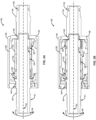
- FIG. 2 illustrates an example rotating power connector 26.
- a rotating stud 40 is configured to mate with an end of the unicable 18, providing a connection to the rotating power connector 26.
- the unicable 18 may be removably or permanently fixed to the rotating power connector 26 by one or more fasteners, such as threaded portion 51, locking screws, and/or set screws, as a list of non-limiting examples.
- the rotating power connector 26 includes a generally cylindrical outer housing 30 having a longitudinal axis 32.
- a connector pin 34 is removably or fixedly arranged within the outer housing 30, aligned with the axis 32 and extending from an end of the rotating power connector 26 opposite the rotating stud 40.
- the connector pin 34 may be generally tubular with a flange portion 38 that secures the connector pin to the outer housing 30.
- a rotating member such as rotating stud 40 is rotatably arranged within the outer housing 30 aligned with the axis 32.
- the rotating stud 40 is also generally tubular with a flange portion 46 at its end.
- An opposite end portion 48 of the rotating stud 40 is arranged outside of the outer housing 30 and is insertable into and connectable to an end of the unicable 18.
- One or more washers, O-rings 49 or similar seals are arranged at the end of the outer housing 30 from which the rotating stud 40 or the connector pin 34 extends.
- An inner housing 50 is arranged within the outer housing 30.
- the inner housing 50 generally extends from one end of the outer housing to the other end and extends to overlap the interface between the connector pin 34 and the rotating stud 40.
- the inner housing 50 generally surrounds the rotating stud 40 and supports the connector pin 34 and the rotating stud.
- One or more electrical contact rings 52, 53 are arranged within the outer housing 30 and between the inner housing 50 and the rotating stud 40.
- each contact ring 52, 53 encircles the rotating stud 40 and includes at least one contact extension 54, 55, which is an extension that contacts the rotating stud 40.
- a contact ring 52 may include multiple contact extensions 54, such as one or more layers and/or spring-loaded, highly conductive fins 99.
- each layer may include a plurality of fins surrounding the rotating stud 40, although the rotating power connector 26 is not limited to any specific number of contact extensions/fins/supporting layers.
- the contact extensions 54 may be fixed to the contact ring 52 at a first end 101, and biased to contact a surface 41 of the rotating stud 40 at a second end 102. In some examples as shown in FIG.
- the contact extension 54 may be fixed to the contact ring 52 at one end 103, and be configured to move (e.g., slide) within the contact ring 52 at another end 104, with a center portion 105 flexing toward the rotating stud 40, thereby ensuring electrical contact as the rotating stud 40 rotates relative to the contact ring 52.
- FIGS. 3D and 3E provide a cross-sectional view of the contact ring 52, fins 99, and rotating stud 40.
- FIG. 3D illustrates rotating stud 40 in coaxial alignment with contact ring 52, such that each of the contact ring 52 and rotating stud 40 share a common axis 110A.
- the rotating stud 40 may be pushed (e.g., in direction 112), which may cause misalignment between the rotating stud 40 and the contact ring 52.
- the rotating stud 40 corresponds to a second axis 110B offset from the axis 110A of the contact ring 52.
- the fins 99 maintain secure contact with the rotating stud 40, as the fins 99 are spring loaded toward the rotating stud 40.
- a bearing 56 also encircles the rotating stud 40 to support the stud during rotational movement.
- the bearing 56 may be arranged about the rotating stud 40 between the contact rings 52, 53 and the flanged end 46 of the rotating stud 40.
- the bearing 56 is a needle roller bearing employing relatively long and/or thin cylindrical rollers resembling needles. Needle bearings can be used to surround the rotating stud 40 in order to reduce the friction and withstand any bending / misalignment force between the rotating stud 40 and the connector pin 34. Needle bearings may be thinner and provide a slimmer profile between the rotating stud 40 and the inner housing 50. In some examples, other types of bearings may be used to suit a specific application.
- a resilient biasing member 58 such as a wave spring or similar, can be arranged between the bearing 56 and the flanged end 46 of the rotating stud 40.
- This biasing member 58 provides limited axial movement between the rotating stud 40 and the bearing 56.
- axial movement of the rotating connector does not disrupt contact between the rotating stud 40 and the contact ring 52 (and/or contact extension 54).
- the biasing member 58 By use of the biasing member 58, a degree of axial flexibility or support is provided along a length of the rotating stud 40.
- the inner housing 50 is configured to receive the contact rings 52, 53 such that each is fixed relative to the housing.
- the contact extensions 54, 55 e.g., fins
- the contact extensions 54, 55 are built into or incorporated with the inner housing 50.
- the rotating power connector 26 allows for the transfer of electricity, as electrical current may pass from the rotating stud 40 through contact extensions 54, 55, and into the connector pin 34.
- the interface between the outer surface 41 and contact extensions 54, 55 is a sliding interface along the path of the current transferring to the rotating power connector 26.
- Other interfaces are fixed or solid connections and are not moveable.
- the connector pin 34 and rotating stud 40 may be made of an electrically conductive materials.
- the inner housing 50 may be made of an electrically conductive materials, and the contact rings 52, 53 may be made of an electrically conductive materials.
- the outer housing 30 may be made of an insulating materials such as a plastic or similar, thereby shielding the outside of the rotating power connector 26 from short-circuiting to external components and/or devices (e.g., the robotic arm 22).
- FIG. 2C provides an illustration of the example rotating power connector 26 enclosed in the housing 30, with the tubular connector pin 34 and tubular rotating stud 40 extending therefrom.
- one or more of the contact extensions 54, 55 are arranged within and/or integrated with one or more of the connector pin 34 or the rotating stud 40 of the rotating power connector 26.
- the contact extensions 54, 55 are biased toward an internal surface 43 of the inner housing 50 to provide electrical contact between the one or more contact extensions 54, 55 and the internal surface 43 during rotation of the rotating power connector 26 relative to a unicable 18.
- the one or more contact extensions 54, 55 are configured with a first end and a second end.
- each contact extension is fixed to an external surface of the rotating stud 40 at the first end and biased to urge the fins outward toward engagement with the internal surface 43 at the second end.
- one or more contact rings 52, 53 is not employed.
- one or more contact rings 52, 53 are used to encircle the rotating stud 40, with the one or more contact extensions 54, 55 arranged on around the one or more contact rings 52, 53.
- the one or more contact extensions 54, 55 extend from an external surface of the one or more contact rings 52, 53 and oriented outward to contact the inner surface 43 of the inner housing 50.
- one or more of the contact extensions 54, 55 are arranged within and/or integrated with the inner housing 50 of the rotating power connector 26 and biased to contact the rotating stud 40 without the use of a contact ring.
- FIG. 4 illustrates another example rotating power connector 26 configured with an integrated direct crimp-on connection 60 (e.g., a crimped-style fitting, a compression fitting, a threaded compression fitting, etc.).
- the direct crimp-on connection 60 is secured to the insert housing 50 via a fastener 62, such as a thread and set screw connection, but may also include a press-fit, knurled press-fit, snap-fit, screws, bolts, adhesive, a weld, braze, or other type of fastener.
- the fastener 62 is secured to the outer housing 30.
- Conductive wires (e.g., copper wires) of the unicable 18 are crimped on the tapered surface 64 to form a solid electric connection between the unicable 18 and the crimp-on connection 60.
- One or more O-rings 49 create a seal between the rotating power connector 26 and the crimp-on connection 60, such that the shielding gas does not leak out of the channel 66, and the lubricant grease does not leak into the channel 66.
- the crimp-on connection 60 includes a male connection with a flared tip 70 and ridge 68, such that a core tube from the unicable 18 is secured by a snap-in feature.
- FIG. 5 provides an illustration of the example rotating power connector 26 enclosed in the housing 30 with the crimp-on connector 60 extending from a first end of the outer housing 30 and the tubular connector pin 34 extending from a second, opposite end.
- one or more power conductors connect directly to the inner housing 50.
- the inner housing 50 is arranged to conduct power through the electrical contact rings 52, 53 via extensions 54, 55, and into the connector pin 34. Electrical current then flows through the connector pin 34 and towards the contact tip.
- the connector pin 34 of the rotating power connector 26 is configured to plug into the main housing 12, thereby connecting the unicable 18 to the nozzle assembly 16 of the welding torch 10.
- a single electrical contact ring 52 is employed.
- three or more electrical contact rings 52, 53 are employed.
- two or more bearings 56 are employed, such as arranged about the tubular rotating stud 40 and bracketing the one or more electrical contact rings 52, as illustrated in FIG. 2B .
- the rotating stud 40 and/or the crimp-on connection 60 extends from an end of the rotating power connector 26 opposite the connector pin 34, and connects to the unicable 18.
- the rotating power connector 26 allows the unicable 18 to rotate relative to the main housing 12.
- the rotatable movement of the unicable 18 provides relief to the otherwise rigid connection through the welding torch 10, significantly reducing the amount of stress on the unicable, extending the useful life of the unicable, which may fail under cyclical or repetitive twisting movements.
- the rotating power connector 26 also allows for the efficient passage of one or more of electrical current, welding wire, and/or shielding gas from the unicable 18 to the nozzle assembly 16, which is a feature for some welding processes (e.g., a MIG welding process, etc.).
- the rotating power connector 26 when the useful life of the rotating power connector 26 has ended, the entire assembly of the unicable 18 and rotating power connector 26 is discarded and replaced in order to replace the rotating power connector.
- the rotating power connector 26 (and/or one or more components therein) is a replaceable component that can be discarded and replaced with another rotating power connector by loosening the fastener(s), separating the unicable 18 from the rotating power connector 26, and attaching a new rotating power connector to the unicable 18.
- the rotating stud 40 and/or the crimp-on connection 60 can be incorporated with the main housing 12 (e.g., via a built in and/or fixed connection), such that the connector pin 34 mates with the unicable 18 (e.g., via a quick-connecting mechanism).
- the rotating power connector 26 are fixedly and/or solidly connected to the unicable 18 and/or the main housing 12
- connection pin 34 and/or rotating stud 40 are described as male-type connections.
- one or both of the connection pin 34 and/or rotating stud 40 can be female-type connections.
- one or both of them can also be flange in the connection design.
- a female connection e.g., the connection pin 34 and/or rotating stud 40
Landscapes
- Engineering & Computer Science (AREA)
- Physics & Mathematics (AREA)
- Mechanical Engineering (AREA)
- Plasma & Fusion (AREA)
- Optics & Photonics (AREA)
- Connector Housings Or Holding Contact Members (AREA)
- Arc Welding In General (AREA)
Claims (13)
- Rotierender Leistungsverbinder (26) für einen elektrischen Schweißbrenner (10), aufweisend:ein Außengehäuse (30) mit einer Längsachse (32);einen Steckerstift (34), der innerhalb des Außengehäuses angeordnet ist und sich von einem ersten Ende des Außengehäuses erstreckt, wobei der Steckerstift konfiguriert ist, in den Schweißbrenner eingeführt zu werden, um den rotierenden Leistungsverbinder mit dem Schweißbrenner zu verbinden;einen Bolzen (40), der innerhalb des Außengehäuses angeordnet ist und sich von einem zweiten Ende des Außengehäuses erstreckt, wobei der Bolzen mit einem Unicable (18) verbindbar ist; undeinen oder mehrere elektrische Kontaktringe (52, 53), die innerhalb des Außengehäuses (30) angeordnet sind und den Steckerstift (34) oder den Bolzen (40) umgeben, wobei der eine oder die mehreren elektrischen Kontaktringe eine oder mehrere Kontakterweiterungen (54, 55) beinhalten, die zu einer Außenfläche (41) des Steckerstifts oder des Bolzens vorgespannt sind, um einen elektrischen Kontakt zwischen der einen oder den mehreren Kontakterweiterungen und der Außenfläche während der Rotation des rotierenden Leistungsverbinders relativ zu dem Unicable bereitzustellen;ein Innengehäuse (50), das innerhalb des Außengehäuses angeordnet ist und im Allgemeinen den einen oder die mehreren Kontaktringe umschließt, wobei das Innengehäuse den einen oder die mehreren Kontaktringe und den Bolzen oder Steckerstift kontaktiert, um einen Strompfad für elektrischen Strom von dem Bolzen durch den einen oder die mehreren Kontaktringe und das Innengehäuse und in den Steckerstift bereitzustellen.
- Rotierender Leistungsverbinder (26) nach Anspruch 1, wobei der Steckerstift so konfiguriert ist, dass er relativ zu dem einen oder den mehreren Kontaktringen (52, 53) rotiert.
- Rotierender Leistungsverbinder (26) nach Anspruch 1, wobei der Bolzen so konfiguriert ist, dass er relativ zu dem einen oder den mehreren Kontaktringen (52, 53) rotiert.
- Rotierender Leistungsverbinder (26) nach Anspruch 3, wobei der Steckerstift (34) und der Bolzen (40) jeweils einen zentralen Kanal (66) zum Kommunizieren eines oder mehrerer von Schutzgas oder Draht aufweisen.
- Rotierender Leistungsverbinder (26) nach Anspruch 1, der ferner ein oder mehrere Lager (56) aufweist, die um den Bolzen (40) herum angeordnet sind, wobei das Lager die Rotation des Steckerstifts (34) oder des Bolzens (40) relativ zu dem Innengehäuse (50) erleichtert; und
optional wobei das Lager ein Nadellager beinhaltet, das zwischen einem Kontaktring des einen oder der mehreren Kontaktringe und dem ersten oder zweiten Ende des Außengehäuses angeordnet ist. - Rotierender Leistungsverbinder (26) nach Anspruch 1, wobei die eine oder mehreren Kontakterweiterungen (54, 55) eine Vielzahl von federbelasteten, hochleitfähigen Lamellen (99) beinhalten; und
optional wobei jede der Vielzahl von Lamellen an einem jeweiligen Kontaktring an einem ersten Ende (101; 103) befestigt und vorgespannt ist, um die Lamellen nach innen hin in den Eingriff an der Außenfläche an einem zweiten Ende (102) oder an einem Abschnitt (105) zwischen dem ersten Ende (103) und dem zweiten Ende (104) zu drücken. - Anordnung für eine Rotationsbewegung eines Schweißbrenner-Unicable, die Anordnung aufweisend:ein Schweißbrenner-Unicable (18);einen Schweißbrenner (10); undeinen Verbinder (26), der das Schweißbrenner-Unicable rotierbar mit einem Schweißbrennerkörper des Schweißbrenners verbindet, sodass das Unicable relativ zu dem Brennerkörper rotierbar ist, wobei der Verbinder den rotierbaren Leistungsverbinder nach Anspruch 1 aufweist, wobei:der Steckerstift (34) fest axial innerhalb des Außengehäuses (30) angeordnet ist;der Bolzen (40) ein Drehbolzen ist, der innerhalb des Außengehäuses angeordnet ist;der Steckerstift in elektrischem Kontakt mit dem Innengehäuse (50) ist; unddie zumindest eine Kontakterweiterung (54, 55) vorgespannt ist, um den Drehbolzen während dessen Rotationsbewegung zu berühren.
- Anordnung nach Anspruch 7, wobei das Unicable (18), der Drehbolzen (40) und der Verbinder (26) jeweils einen Durchgang (66) entlang einer gemeinsamen Achse (32) zur Überführung eines Schweißdrahtes oder eines Schutzgases zu dem Schweißbrenner (10) beinhalten.
- Rotierbarer Leistungsverbinder (26) für einen elektrischen Schweißbrenner (10), aufweisend:ein Außengehäuse (30) mit einer Längsachse (32);einen Steckerstift (34), der innerhalb des Außengehäuses angeordnet ist und sich von einem ersten Ende des Außengehäuses erstreckt, wobei der Steckerstift konfiguriert ist, in einen Schweißbrenner eingeführt zu werden, um den rotierenden Leistungsverbinder mit dem Schweißbrenner zu verbinden;einen Bolzen (40), der innerhalb des Außengehäuses angeordnet ist und sich von einem zweiten Ende des Außengehäuses erstreckt, wobei der Bolzen mit einem Unicable (18) verbindbar ist;ein Innengehäuse (50), das innerhalb des Außengehäuses angeordnet ist; undeine oder mehrere Kontakterweiterungen (54, 55), die innerhalb des Außengehäuses (30) angeordnet sind und einen oder mehrere des Steckerstifts (34) oder des Bolzens (40) umgeben, wobei die eine oder mehreren Kontakterweiterungen hin zu einer Innenfläche (43) des Innengehäuses (50) vorgespannt sind, um einen elektrischen Kontakt zwischen der einen oder den mehreren Kontakterweiterungen und der Innenfläche während der Rotation des rotierenden Leistungsverbinders relativ zu dem Unicable (18) bereitzustellen,wobei das Innengehäuse den Bolzen oder Steckerstift kontaktiert, um einen Strompfad für elektrischen Strom von dem Bolzen durch den einen oder die mehreren Kontakterweiterungen und das Innengehäuse und in den Steckerstift bereitzustellen.
- Rotierender Leistungsverbinder (26) nach Anspruch 9, wobei die eine oder mehreren Kontakterweiterungen (54, 55) eine Vielzahl von Lamellen beinhalten, wobei jede Lamelle ein erstes Ende und ein zweites Ende aufweist; und
optional wobei jede der Vielzahl von Lamellen an einer Außenfläche des Bolzens (40) an dem ersten Ende befestigt ist und vorgespannt ist, um die Lamellen nach außen hin in den Eingriff an der Innenfläche (43) an dem zweiten Ende zu drücken. - Rotierender Leistungsverbinder (26) nach Anspruch 9, wobei der Steckerstift so konfiguriert ist, dass er sich relativ zu dem Innengehäuse (50) dreht.
- Rotierender Leistungsverbinder (26) nach Anspruch 9, wobei der Bolzen (40) so konfiguriert ist, dass er sich relativ zu dem Innengehäuse (50) dreht.
- Rotierender Leistungsverbinder (26) nach Anspruch 9, der ferner ein oder mehrere Lager (58) aufweist, die um den Bolzen (40) oder den Kontaktstift (34) herum angeordnet sind, wobei das Lager die Rotation des Steckerstifts oder Bolzens relativ zu dem Innengehäuse (50) erleichtert; und
optional wobei das Lager ein Nadellager beinhaltet, das zwischen der einen oder den mehreren Kontakterweiterungen und dem ersten oder zweiten Ende des Außengehäuses angeordnet ist.
Priority Applications (1)
| Application Number | Priority Date | Filing Date | Title |
|---|---|---|---|
| EP24192097.4A EP4431226A3 (de) | 2020-09-11 | 2021-09-06 | Rotierender leistungsverbinder für schweissbrennerkabel |
Applications Claiming Priority (2)
| Application Number | Priority Date | Filing Date | Title |
|---|---|---|---|
| US202063077353P | 2020-09-11 | 2020-09-11 | |
| US17/411,384 US11883915B2 (en) | 2020-09-11 | 2021-08-25 | Rotating power connector for welding torch cables |
Related Child Applications (1)
| Application Number | Title | Priority Date | Filing Date |
|---|---|---|---|
| EP24192097.4A Division EP4431226A3 (de) | 2020-09-11 | 2021-09-06 | Rotierender leistungsverbinder für schweissbrennerkabel |
Publications (2)
| Publication Number | Publication Date |
|---|---|
| EP3968472A1 EP3968472A1 (de) | 2022-03-16 |
| EP3968472B1 true EP3968472B1 (de) | 2024-08-21 |
Family
ID=77640555
Family Applications (2)
| Application Number | Title | Priority Date | Filing Date |
|---|---|---|---|
| EP24192097.4A Pending EP4431226A3 (de) | 2020-09-11 | 2021-09-06 | Rotierender leistungsverbinder für schweissbrennerkabel |
| EP21194991.2A Active EP3968472B1 (de) | 2020-09-11 | 2021-09-06 | Rotierender leistungsverbinder für schweissbrennerkabel |
Family Applications Before (1)
| Application Number | Title | Priority Date | Filing Date |
|---|---|---|---|
| EP24192097.4A Pending EP4431226A3 (de) | 2020-09-11 | 2021-09-06 | Rotierender leistungsverbinder für schweissbrennerkabel |
Country Status (4)
| Country | Link |
|---|---|
| US (1) | US11883915B2 (de) |
| EP (2) | EP4431226A3 (de) |
| CN (1) | CN114160937A (de) |
| CA (1) | CA3129568A1 (de) |
Families Citing this family (6)
| Publication number | Priority date | Publication date | Assignee | Title |
|---|---|---|---|---|
| US10773332B2 (en) * | 2015-09-18 | 2020-09-15 | Illinois Tool Works Inc. | Contact tip and receiving assembly of a welding torch |
| US20220288716A1 (en) * | 2021-03-11 | 2022-09-15 | Lincoln Global, Inc. | Flexible welding gun tube |
| CN117532654A (zh) * | 2022-04-19 | 2024-02-09 | 南京国信能源有限公司 | 电力传导机械臂及使用该机器臂的系统 |
| US20240396277A1 (en) * | 2023-05-25 | 2024-11-28 | Illinois Tool Works Inc. | Rotating power connector for welding torch cables |
| US20250357713A1 (en) * | 2024-05-15 | 2025-11-20 | Illinois Tool Works Inc. | Wire feeding systems with built-in rotating power connectors |
| US20250367750A1 (en) * | 2024-05-30 | 2025-12-04 | Illinois Tool Works Inc. | Stand-alone rotating power adapters |
Family Cites Families (10)
| Publication number | Priority date | Publication date | Assignee | Title |
|---|---|---|---|---|
| US3909585A (en) * | 1974-05-13 | 1975-09-30 | Central Welding Supply Co | Arc welding torch |
| GB1588319A (en) * | 1977-06-29 | 1981-04-23 | Foster Wheeler Power Prod | Internal bore arc welding torch |
| US4336974A (en) * | 1978-11-13 | 1982-06-29 | Microwave Development Labs. Inc. | Coaxial rotary joint |
| US4549068A (en) * | 1983-12-09 | 1985-10-22 | Kensrue Milo M | Welding torch having swivel head assembly |
| DE4325289A1 (de) | 1993-07-28 | 1995-04-06 | T & B Schweistechnik Gmbh | Schweißkabelanschluß für Lichtbogenhand- und Lichtbogenautomaten-Schweiß- und Schneidbrenner |
| US7665996B2 (en) | 2007-02-02 | 2010-02-23 | Illinois Tool Works Inc. | Rotating power connector for electric welding torch unicables |
| AT509982B1 (de) | 2010-08-09 | 2012-01-15 | Fronius Int Gmbh | Befestigungssystem eines brennerkörpers eines wig-schweissbrenners, brennerkörper und wig-schweissbrenner |
| JP5462231B2 (ja) | 2011-10-24 | 2014-04-02 | ヒロセ電機株式会社 | 電気コネクタ組立体 |
| US10766093B2 (en) * | 2016-11-15 | 2020-09-08 | American Torch Tip, Co. | Reduced friction rotating coupler assembly and quick disconnect for use with welding devices |
| EP3635819A1 (de) | 2017-06-08 | 2020-04-15 | Stäubli Electrical Connectors AG | Elektrisches verbindungselement |
-
2021
- 2021-08-25 US US17/411,384 patent/US11883915B2/en active Active
- 2021-09-01 CA CA3129568A patent/CA3129568A1/en active Pending
- 2021-09-06 EP EP24192097.4A patent/EP4431226A3/de active Pending
- 2021-09-06 EP EP21194991.2A patent/EP3968472B1/de active Active
- 2021-09-09 CN CN202111054889.8A patent/CN114160937A/zh active Pending
Also Published As
| Publication number | Publication date |
|---|---|
| US11883915B2 (en) | 2024-01-30 |
| EP4431226A3 (de) | 2024-11-20 |
| EP4431226A2 (de) | 2024-09-18 |
| EP3968472A1 (de) | 2022-03-16 |
| US20220080521A1 (en) | 2022-03-17 |
| CN114160937A (zh) | 2022-03-11 |
| US20240157461A1 (en) | 2024-05-16 |
| CA3129568A1 (en) | 2022-03-11 |
Similar Documents
| Publication | Publication Date | Title |
|---|---|---|
| EP3968472B1 (de) | Rotierender leistungsverbinder für schweissbrennerkabel | |
| EP2109513B1 (de) | Drehender stromanschluss für electrische schweissbrenner | |
| US12046855B2 (en) | Welding power cable for connecting to a welding power source in order to carry out an arc welding method | |
| US20090045183A1 (en) | Welding Torch and End Piece as Well as Contact Tube for a Welding Torch | |
| JP2021514099A (ja) | 適応性多目的空圧電気コネクタ | |
| US7294809B2 (en) | Configurable securing assembly for neck of welding gun | |
| EP4251359B1 (de) | Auslösemechanismus mit drehbarem leistungsanschluss für einen halbautomatischen schweissbrenner | |
| US12491575B2 (en) | Rotating power connector for welding torch cables | |
| US20240391013A1 (en) | Method of Rotating a Welding Torch During Operation | |
| US20250050443A1 (en) | Dynamic connectors for welding cables and welding torches | |
| US20240316680A1 (en) | Floating core tube in welding torch cables | |
| CN115038542B (zh) | 电弧焊炬 | |
| US20240396277A1 (en) | Rotating power connector for welding torch cables | |
| WO2024197129A1 (en) | Welding torch cables with floating core tube | |
| US10766093B2 (en) | Reduced friction rotating coupler assembly and quick disconnect for use with welding devices | |
| US20240307994A1 (en) | Ultrasonically welded fittings and welding cables | |
| US20250367750A1 (en) | Stand-alone rotating power adapters | |
| US11654502B2 (en) | Method of rotating a welding torch during operation | |
| EP4653118A1 (de) | Drahtzuführsysteme mit eingebauten rotierenden leistungsverbindern | |
| WO2024192368A1 (en) | Ultrasonically welded fittings and welding cables | |
| AT512823A1 (de) | Motorplatte für eine Schweißanlage |
Legal Events
| Date | Code | Title | Description |
|---|---|---|---|
| PUAI | Public reference made under article 153(3) epc to a published international application that has entered the european phase |
Free format text: ORIGINAL CODE: 0009012 |
|
| STAA | Information on the status of an ep patent application or granted ep patent |
Free format text: STATUS: THE APPLICATION HAS BEEN PUBLISHED |
|
| AK | Designated contracting states |
Kind code of ref document: A1 Designated state(s): AL AT BE BG CH CY CZ DE DK EE ES FI FR GB GR HR HU IE IS IT LI LT LU LV MC MK MT NL NO PL PT RO RS SE SI SK SM TR |
|
| STAA | Information on the status of an ep patent application or granted ep patent |
Free format text: STATUS: REQUEST FOR EXAMINATION WAS MADE |
|
| 17P | Request for examination filed |
Effective date: 20220913 |
|
| RBV | Designated contracting states (corrected) |
Designated state(s): AL AT BE BG CH CY CZ DE DK EE ES FI FR GB GR HR HU IE IS IT LI LT LU LV MC MK MT NL NO PL PT RO RS SE SI SK SM TR |
|
| GRAP | Despatch of communication of intention to grant a patent |
Free format text: ORIGINAL CODE: EPIDOSNIGR1 |
|
| STAA | Information on the status of an ep patent application or granted ep patent |
Free format text: STATUS: GRANT OF PATENT IS INTENDED |
|
| RIC1 | Information provided on ipc code assigned before grant |
Ipc: H01R 13/11 20060101ALN20240229BHEP Ipc: B23K 37/02 20060101ALI20240229BHEP Ipc: B23K 9/32 20060101ALI20240229BHEP Ipc: H01R 39/64 20060101AFI20240229BHEP |
|
| INTG | Intention to grant announced |
Effective date: 20240315 |
|
| P01 | Opt-out of the competence of the unified patent court (upc) registered |
Effective date: 20240425 |
|
| GRAS | Grant fee paid |
Free format text: ORIGINAL CODE: EPIDOSNIGR3 |
|
| GRAA | (expected) grant |
Free format text: ORIGINAL CODE: 0009210 |
|
| STAA | Information on the status of an ep patent application or granted ep patent |
Free format text: STATUS: THE PATENT HAS BEEN GRANTED |
|
| AK | Designated contracting states |
Kind code of ref document: B1 Designated state(s): AL AT BE BG CH CY CZ DE DK EE ES FI FR GB GR HR HU IE IS IT LI LT LU LV MC MK MT NL NO PL PT RO RS SE SI SK SM TR |
|
| REG | Reference to a national code |
Ref country code: GB Ref legal event code: FG4D |
|
| REG | Reference to a national code |
Ref country code: CH Ref legal event code: EP |
|
| REG | Reference to a national code |
Ref country code: IE Ref legal event code: FG4D |
|
| REG | Reference to a national code |
Ref country code: DE Ref legal event code: R096 Ref document number: 602021017434 Country of ref document: DE |
|
| REG | Reference to a national code |
Ref country code: LT Ref legal event code: MG9D |
|
| REG | Reference to a national code |
Ref country code: NL Ref legal event code: MP Effective date: 20240821 |
|
| PG25 | Lapsed in a contracting state [announced via postgrant information from national office to epo] |
Ref country code: NO Free format text: LAPSE BECAUSE OF FAILURE TO SUBMIT A TRANSLATION OF THE DESCRIPTION OR TO PAY THE FEE WITHIN THE PRESCRIBED TIME-LIMIT Effective date: 20241121 |
|
| REG | Reference to a national code |
Ref country code: AT Ref legal event code: MK05 Ref document number: 1716470 Country of ref document: AT Kind code of ref document: T Effective date: 20240821 |
|
| PG25 | Lapsed in a contracting state [announced via postgrant information from national office to epo] |
Ref country code: NL Free format text: LAPSE BECAUSE OF FAILURE TO SUBMIT A TRANSLATION OF THE DESCRIPTION OR TO PAY THE FEE WITHIN THE PRESCRIBED TIME-LIMIT Effective date: 20240821 Ref country code: FI Free format text: LAPSE BECAUSE OF FAILURE TO SUBMIT A TRANSLATION OF THE DESCRIPTION OR TO PAY THE FEE WITHIN THE PRESCRIBED TIME-LIMIT Effective date: 20240821 Ref country code: PL Free format text: LAPSE BECAUSE OF FAILURE TO SUBMIT A TRANSLATION OF THE DESCRIPTION OR TO PAY THE FEE WITHIN THE PRESCRIBED TIME-LIMIT Effective date: 20240821 Ref country code: GR Free format text: LAPSE BECAUSE OF FAILURE TO SUBMIT A TRANSLATION OF THE DESCRIPTION OR TO PAY THE FEE WITHIN THE PRESCRIBED TIME-LIMIT Effective date: 20241122 Ref country code: PT Free format text: LAPSE BECAUSE OF FAILURE TO SUBMIT A TRANSLATION OF THE DESCRIPTION OR TO PAY THE FEE WITHIN THE PRESCRIBED TIME-LIMIT Effective date: 20241223 |
|
| PG25 | Lapsed in a contracting state [announced via postgrant information from national office to epo] |
Ref country code: BG Free format text: LAPSE BECAUSE OF FAILURE TO SUBMIT A TRANSLATION OF THE DESCRIPTION OR TO PAY THE FEE WITHIN THE PRESCRIBED TIME-LIMIT Effective date: 20240821 |
|
| PG25 | Lapsed in a contracting state [announced via postgrant information from national office to epo] |
Ref country code: LV Free format text: LAPSE BECAUSE OF FAILURE TO SUBMIT A TRANSLATION OF THE DESCRIPTION OR TO PAY THE FEE WITHIN THE PRESCRIBED TIME-LIMIT Effective date: 20240821 |
|
| PG25 | Lapsed in a contracting state [announced via postgrant information from national office to epo] |
Ref country code: AT Free format text: LAPSE BECAUSE OF FAILURE TO SUBMIT A TRANSLATION OF THE DESCRIPTION OR TO PAY THE FEE WITHIN THE PRESCRIBED TIME-LIMIT Effective date: 20240821 Ref country code: IS Free format text: LAPSE BECAUSE OF FAILURE TO SUBMIT A TRANSLATION OF THE DESCRIPTION OR TO PAY THE FEE WITHIN THE PRESCRIBED TIME-LIMIT Effective date: 20241221 |
|
| PG25 | Lapsed in a contracting state [announced via postgrant information from national office to epo] |
Ref country code: HR Free format text: LAPSE BECAUSE OF FAILURE TO SUBMIT A TRANSLATION OF THE DESCRIPTION OR TO PAY THE FEE WITHIN THE PRESCRIBED TIME-LIMIT Effective date: 20240821 |
|
| PG25 | Lapsed in a contracting state [announced via postgrant information from national office to epo] |
Ref country code: RS Free format text: LAPSE BECAUSE OF FAILURE TO SUBMIT A TRANSLATION OF THE DESCRIPTION OR TO PAY THE FEE WITHIN THE PRESCRIBED TIME-LIMIT Effective date: 20241121 Ref country code: ES Free format text: LAPSE BECAUSE OF FAILURE TO SUBMIT A TRANSLATION OF THE DESCRIPTION OR TO PAY THE FEE WITHIN THE PRESCRIBED TIME-LIMIT Effective date: 20240821 |
|
| PG25 | Lapsed in a contracting state [announced via postgrant information from national office to epo] |
Ref country code: RS Free format text: LAPSE BECAUSE OF FAILURE TO SUBMIT A TRANSLATION OF THE DESCRIPTION OR TO PAY THE FEE WITHIN THE PRESCRIBED TIME-LIMIT Effective date: 20241121 Ref country code: PT Free format text: LAPSE BECAUSE OF FAILURE TO SUBMIT A TRANSLATION OF THE DESCRIPTION OR TO PAY THE FEE WITHIN THE PRESCRIBED TIME-LIMIT Effective date: 20241223 Ref country code: PL Free format text: LAPSE BECAUSE OF FAILURE TO SUBMIT A TRANSLATION OF THE DESCRIPTION OR TO PAY THE FEE WITHIN THE PRESCRIBED TIME-LIMIT Effective date: 20240821 Ref country code: NO Free format text: LAPSE BECAUSE OF FAILURE TO SUBMIT A TRANSLATION OF THE DESCRIPTION OR TO PAY THE FEE WITHIN THE PRESCRIBED TIME-LIMIT Effective date: 20241121 Ref country code: NL Free format text: LAPSE BECAUSE OF FAILURE TO SUBMIT A TRANSLATION OF THE DESCRIPTION OR TO PAY THE FEE WITHIN THE PRESCRIBED TIME-LIMIT Effective date: 20240821 Ref country code: LV Free format text: LAPSE BECAUSE OF FAILURE TO SUBMIT A TRANSLATION OF THE DESCRIPTION OR TO PAY THE FEE WITHIN THE PRESCRIBED TIME-LIMIT Effective date: 20240821 Ref country code: IS Free format text: LAPSE BECAUSE OF FAILURE TO SUBMIT A TRANSLATION OF THE DESCRIPTION OR TO PAY THE FEE WITHIN THE PRESCRIBED TIME-LIMIT Effective date: 20241221 Ref country code: HR Free format text: LAPSE BECAUSE OF FAILURE TO SUBMIT A TRANSLATION OF THE DESCRIPTION OR TO PAY THE FEE WITHIN THE PRESCRIBED TIME-LIMIT Effective date: 20240821 Ref country code: GR Free format text: LAPSE BECAUSE OF FAILURE TO SUBMIT A TRANSLATION OF THE DESCRIPTION OR TO PAY THE FEE WITHIN THE PRESCRIBED TIME-LIMIT Effective date: 20241122 Ref country code: FI Free format text: LAPSE BECAUSE OF FAILURE TO SUBMIT A TRANSLATION OF THE DESCRIPTION OR TO PAY THE FEE WITHIN THE PRESCRIBED TIME-LIMIT Effective date: 20240821 Ref country code: ES Free format text: LAPSE BECAUSE OF FAILURE TO SUBMIT A TRANSLATION OF THE DESCRIPTION OR TO PAY THE FEE WITHIN THE PRESCRIBED TIME-LIMIT Effective date: 20240821 Ref country code: BG Free format text: LAPSE BECAUSE OF FAILURE TO SUBMIT A TRANSLATION OF THE DESCRIPTION OR TO PAY THE FEE WITHIN THE PRESCRIBED TIME-LIMIT Effective date: 20240821 Ref country code: AT Free format text: LAPSE BECAUSE OF FAILURE TO SUBMIT A TRANSLATION OF THE DESCRIPTION OR TO PAY THE FEE WITHIN THE PRESCRIBED TIME-LIMIT Effective date: 20240821 |
|
| PG25 | Lapsed in a contracting state [announced via postgrant information from national office to epo] |
Ref country code: RO Free format text: LAPSE BECAUSE OF FAILURE TO SUBMIT A TRANSLATION OF THE DESCRIPTION OR TO PAY THE FEE WITHIN THE PRESCRIBED TIME-LIMIT Effective date: 20240821 Ref country code: SM Free format text: LAPSE BECAUSE OF FAILURE TO SUBMIT A TRANSLATION OF THE DESCRIPTION OR TO PAY THE FEE WITHIN THE PRESCRIBED TIME-LIMIT Effective date: 20240821 Ref country code: DK Free format text: LAPSE BECAUSE OF FAILURE TO SUBMIT A TRANSLATION OF THE DESCRIPTION OR TO PAY THE FEE WITHIN THE PRESCRIBED TIME-LIMIT Effective date: 20240821 |
|
| PG25 | Lapsed in a contracting state [announced via postgrant information from national office to epo] |
Ref country code: EE Free format text: LAPSE BECAUSE OF FAILURE TO SUBMIT A TRANSLATION OF THE DESCRIPTION OR TO PAY THE FEE WITHIN THE PRESCRIBED TIME-LIMIT Effective date: 20240821 |
|
| PG25 | Lapsed in a contracting state [announced via postgrant information from national office to epo] |
Ref country code: CZ Free format text: LAPSE BECAUSE OF FAILURE TO SUBMIT A TRANSLATION OF THE DESCRIPTION OR TO PAY THE FEE WITHIN THE PRESCRIBED TIME-LIMIT Effective date: 20240821 |
|
| PG25 | Lapsed in a contracting state [announced via postgrant information from national office to epo] |
Ref country code: SK Free format text: LAPSE BECAUSE OF FAILURE TO SUBMIT A TRANSLATION OF THE DESCRIPTION OR TO PAY THE FEE WITHIN THE PRESCRIBED TIME-LIMIT Effective date: 20240821 |
|
| REG | Reference to a national code |
Ref country code: CH Ref legal event code: PL |
|
| PG25 | Lapsed in a contracting state [announced via postgrant information from national office to epo] |
Ref country code: LU Free format text: LAPSE BECAUSE OF NON-PAYMENT OF DUE FEES Effective date: 20240906 |
|
| REG | Reference to a national code |
Ref country code: DE Ref legal event code: R097 Ref document number: 602021017434 Country of ref document: DE |
|
| PLBE | No opposition filed within time limit |
Free format text: ORIGINAL CODE: 0009261 |
|
| STAA | Information on the status of an ep patent application or granted ep patent |
Free format text: STATUS: NO OPPOSITION FILED WITHIN TIME LIMIT |
|
| PG25 | Lapsed in a contracting state [announced via postgrant information from national office to epo] |
Ref country code: MC Free format text: LAPSE BECAUSE OF FAILURE TO SUBMIT A TRANSLATION OF THE DESCRIPTION OR TO PAY THE FEE WITHIN THE PRESCRIBED TIME-LIMIT Effective date: 20240821 |
|
| REG | Reference to a national code |
Ref country code: BE Ref legal event code: MM Effective date: 20240930 |
|
| PG25 | Lapsed in a contracting state [announced via postgrant information from national office to epo] |
Ref country code: BE Free format text: LAPSE BECAUSE OF NON-PAYMENT OF DUE FEES Effective date: 20240930 |
|
| PG25 | Lapsed in a contracting state [announced via postgrant information from national office to epo] |
Ref country code: CH Free format text: LAPSE BECAUSE OF NON-PAYMENT OF DUE FEES Effective date: 20240930 |
|
| PG25 | Lapsed in a contracting state [announced via postgrant information from national office to epo] |
Ref country code: IE Free format text: LAPSE BECAUSE OF NON-PAYMENT OF DUE FEES Effective date: 20240906 |
|
| 26N | No opposition filed |
Effective date: 20250522 |
|
| PG25 | Lapsed in a contracting state [announced via postgrant information from national office to epo] |
Ref country code: SE Free format text: LAPSE BECAUSE OF FAILURE TO SUBMIT A TRANSLATION OF THE DESCRIPTION OR TO PAY THE FEE WITHIN THE PRESCRIBED TIME-LIMIT Effective date: 20240821 |
|
| PGFP | Annual fee paid to national office [announced via postgrant information from national office to epo] |
Ref country code: DE Payment date: 20250929 Year of fee payment: 5 |
|
| PGFP | Annual fee paid to national office [announced via postgrant information from national office to epo] |
Ref country code: IT Payment date: 20250919 Year of fee payment: 5 |
|
| PGFP | Annual fee paid to national office [announced via postgrant information from national office to epo] |
Ref country code: GB Payment date: 20250929 Year of fee payment: 5 |
|
| PGFP | Annual fee paid to national office [announced via postgrant information from national office to epo] |
Ref country code: FR Payment date: 20250925 Year of fee payment: 5 |