EP3968305A1 - Method, computer program and apparatus for controlling operation of a vehicle equipped with an automated driving function - Google Patents
Method, computer program and apparatus for controlling operation of a vehicle equipped with an automated driving function Download PDFInfo
- Publication number
- EP3968305A1 EP3968305A1 EP20196200.8A EP20196200A EP3968305A1 EP 3968305 A1 EP3968305 A1 EP 3968305A1 EP 20196200 A EP20196200 A EP 20196200A EP 3968305 A1 EP3968305 A1 EP 3968305A1
- Authority
- EP
- European Patent Office
- Prior art keywords
- vehicle
- signal state
- information
- traffic light
- determined
- Prior art date
- Legal status (The legal status is an assumption and is not a legal conclusion. Google has not performed a legal analysis and makes no representation as to the accuracy of the status listed.)
- Granted
Links
Images



Classifications
-
- B—PERFORMING OPERATIONS; TRANSPORTING
- B60—VEHICLES IN GENERAL
- B60W—CONJOINT CONTROL OF VEHICLE SUB-UNITS OF DIFFERENT TYPE OR DIFFERENT FUNCTION; CONTROL SYSTEMS SPECIALLY ADAPTED FOR HYBRID VEHICLES; ROAD VEHICLE DRIVE CONTROL SYSTEMS FOR PURPOSES NOT RELATED TO THE CONTROL OF A PARTICULAR SUB-UNIT
- B60W60/00—Drive control systems specially adapted for autonomous road vehicles
- B60W60/001—Planning or execution of driving tasks
- B60W60/0015—Planning or execution of driving tasks specially adapted for safety
- B60W60/0018—Planning or execution of driving tasks specially adapted for safety by employing degraded modes, e.g. reducing speed, in response to suboptimal conditions
- B60W60/00184—Planning or execution of driving tasks specially adapted for safety by employing degraded modes, e.g. reducing speed, in response to suboptimal conditions related to infrastructure
-
- G—PHYSICS
- G08—SIGNALLING
- G08G—TRAFFIC CONTROL SYSTEMS
- G08G1/00—Traffic control systems for road vehicles
- G08G1/09—Arrangements for giving variable traffic instructions
- G08G1/096—Arrangements for giving variable traffic instructions provided with indicators in which a mark progresses showing the time elapsed, e.g. of green phase
-
- B—PERFORMING OPERATIONS; TRANSPORTING
- B60—VEHICLES IN GENERAL
- B60W—CONJOINT CONTROL OF VEHICLE SUB-UNITS OF DIFFERENT TYPE OR DIFFERENT FUNCTION; CONTROL SYSTEMS SPECIALLY ADAPTED FOR HYBRID VEHICLES; ROAD VEHICLE DRIVE CONTROL SYSTEMS FOR PURPOSES NOT RELATED TO THE CONTROL OF A PARTICULAR SUB-UNIT
- B60W30/00—Purposes of road vehicle drive control systems not related to the control of a particular sub-unit, e.g. of systems using conjoint control of vehicle sub-units
- B60W30/18—Propelling the vehicle
- B60W30/182—Selecting between different operative modes, e.g. comfort and performance modes
-
- B—PERFORMING OPERATIONS; TRANSPORTING
- B60—VEHICLES IN GENERAL
- B60W—CONJOINT CONTROL OF VEHICLE SUB-UNITS OF DIFFERENT TYPE OR DIFFERENT FUNCTION; CONTROL SYSTEMS SPECIALLY ADAPTED FOR HYBRID VEHICLES; ROAD VEHICLE DRIVE CONTROL SYSTEMS FOR PURPOSES NOT RELATED TO THE CONTROL OF A PARTICULAR SUB-UNIT
- B60W40/00—Estimation or calculation of non-directly measurable driving parameters for road vehicle drive control systems not related to the control of a particular sub unit, e.g. by using mathematical models
- B60W40/02—Estimation or calculation of non-directly measurable driving parameters for road vehicle drive control systems not related to the control of a particular sub unit, e.g. by using mathematical models related to ambient conditions
- B60W40/04—Traffic conditions
-
- B—PERFORMING OPERATIONS; TRANSPORTING
- B60—VEHICLES IN GENERAL
- B60W—CONJOINT CONTROL OF VEHICLE SUB-UNITS OF DIFFERENT TYPE OR DIFFERENT FUNCTION; CONTROL SYSTEMS SPECIALLY ADAPTED FOR HYBRID VEHICLES; ROAD VEHICLE DRIVE CONTROL SYSTEMS FOR PURPOSES NOT RELATED TO THE CONTROL OF A PARTICULAR SUB-UNIT
- B60W60/00—Drive control systems specially adapted for autonomous road vehicles
- B60W60/001—Planning or execution of driving tasks
- B60W60/0015—Planning or execution of driving tasks specially adapted for safety
-
- B—PERFORMING OPERATIONS; TRANSPORTING
- B60—VEHICLES IN GENERAL
- B60W—CONJOINT CONTROL OF VEHICLE SUB-UNITS OF DIFFERENT TYPE OR DIFFERENT FUNCTION; CONTROL SYSTEMS SPECIALLY ADAPTED FOR HYBRID VEHICLES; ROAD VEHICLE DRIVE CONTROL SYSTEMS FOR PURPOSES NOT RELATED TO THE CONTROL OF A PARTICULAR SUB-UNIT
- B60W60/00—Drive control systems specially adapted for autonomous road vehicles
- B60W60/001—Planning or execution of driving tasks
- B60W60/0027—Planning or execution of driving tasks using trajectory prediction for other traffic participants
- B60W60/00274—Planning or execution of driving tasks using trajectory prediction for other traffic participants considering possible movement changes
-
- G—PHYSICS
- G06—COMPUTING OR CALCULATING; COUNTING
- G06V—IMAGE OR VIDEO RECOGNITION OR UNDERSTANDING
- G06V20/00—Scenes; Scene-specific elements
- G06V20/50—Context or environment of the image
- G06V20/56—Context or environment of the image exterior to a vehicle by using sensors mounted on the vehicle
- G06V20/58—Recognition of moving objects or obstacles, e.g. vehicles or pedestrians; Recognition of traffic objects, e.g. traffic signs, traffic lights or roads
- G06V20/584—Recognition of moving objects or obstacles, e.g. vehicles or pedestrians; Recognition of traffic objects, e.g. traffic signs, traffic lights or roads of vehicle lights or traffic lights
-
- G—PHYSICS
- G08—SIGNALLING
- G08G—TRAFFIC CONTROL SYSTEMS
- G08G1/00—Traffic control systems for road vehicles
- G08G1/09—Arrangements for giving variable traffic instructions
- G08G1/091—Traffic information broadcasting
-
- G—PHYSICS
- G08—SIGNALLING
- G08G—TRAFFIC CONTROL SYSTEMS
- G08G1/00—Traffic control systems for road vehicles
- G08G1/09—Arrangements for giving variable traffic instructions
- G08G1/0962—Arrangements for giving variable traffic instructions having an indicator mounted inside the vehicle, e.g. giving voice messages
- G08G1/09623—Systems involving the acquisition of information from passive traffic signs by means mounted on the vehicle
-
- G—PHYSICS
- G08—SIGNALLING
- G08G—TRAFFIC CONTROL SYSTEMS
- G08G1/00—Traffic control systems for road vehicles
- G08G1/09—Arrangements for giving variable traffic instructions
- G08G1/0962—Arrangements for giving variable traffic instructions having an indicator mounted inside the vehicle, e.g. giving voice messages
- G08G1/09626—Arrangements for giving variable traffic instructions having an indicator mounted inside the vehicle, e.g. giving voice messages where the origin of the information is within the own vehicle, e.g. a local storage device, digital map
-
- G—PHYSICS
- G08—SIGNALLING
- G08G—TRAFFIC CONTROL SYSTEMS
- G08G1/00—Traffic control systems for road vehicles
- G08G1/09—Arrangements for giving variable traffic instructions
- G08G1/0962—Arrangements for giving variable traffic instructions having an indicator mounted inside the vehicle, e.g. giving voice messages
- G08G1/0967—Systems involving transmission of highway information, e.g. weather, speed limits
- G08G1/096708—Systems involving transmission of highway information, e.g. weather, speed limits where the received information might be used to generate an automatic action on the vehicle control
- G08G1/096725—Systems involving transmission of highway information, e.g. weather, speed limits where the received information might be used to generate an automatic action on the vehicle control where the received information generates an automatic action on the vehicle control
-
- G—PHYSICS
- G08—SIGNALLING
- G08G—TRAFFIC CONTROL SYSTEMS
- G08G1/00—Traffic control systems for road vehicles
- G08G1/09—Arrangements for giving variable traffic instructions
- G08G1/0962—Arrangements for giving variable traffic instructions having an indicator mounted inside the vehicle, e.g. giving voice messages
- G08G1/0967—Systems involving transmission of highway information, e.g. weather, speed limits
- G08G1/096766—Systems involving transmission of highway information, e.g. weather, speed limits where the system is characterised by the origin of the information transmission
- G08G1/096783—Systems involving transmission of highway information, e.g. weather, speed limits where the system is characterised by the origin of the information transmission where the origin of the information is a roadside individual element
-
- G—PHYSICS
- G08—SIGNALLING
- G08G—TRAFFIC CONTROL SYSTEMS
- G08G1/00—Traffic control systems for road vehicles
- G08G1/09—Arrangements for giving variable traffic instructions
- G08G1/0962—Arrangements for giving variable traffic instructions having an indicator mounted inside the vehicle, e.g. giving voice messages
- G08G1/0968—Systems involving transmission of navigation instructions to the vehicle
- G08G1/0969—Systems involving transmission of navigation instructions to the vehicle having a display in the form of a map
-
- H—ELECTRICITY
- H04—ELECTRIC COMMUNICATION TECHNIQUE
- H04W—WIRELESS COMMUNICATION NETWORKS
- H04W4/00—Services specially adapted for wireless communication networks; Facilities therefor
- H04W4/30—Services specially adapted for particular environments, situations or purposes
- H04W4/40—Services specially adapted for particular environments, situations or purposes for vehicles, e.g. vehicle-to-pedestrians [V2P]
- H04W4/44—Services specially adapted for particular environments, situations or purposes for vehicles, e.g. vehicle-to-pedestrians [V2P] for communication between vehicles and infrastructures, e.g. vehicle-to-cloud [V2C] or vehicle-to-home [V2H]
-
- B—PERFORMING OPERATIONS; TRANSPORTING
- B60—VEHICLES IN GENERAL
- B60W—CONJOINT CONTROL OF VEHICLE SUB-UNITS OF DIFFERENT TYPE OR DIFFERENT FUNCTION; CONTROL SYSTEMS SPECIALLY ADAPTED FOR HYBRID VEHICLES; ROAD VEHICLE DRIVE CONTROL SYSTEMS FOR PURPOSES NOT RELATED TO THE CONTROL OF A PARTICULAR SUB-UNIT
- B60W50/00—Details of control systems for road vehicle drive control not related to the control of a particular sub-unit, e.g. process diagnostic or vehicle driver interfaces
- B60W2050/0062—Adapting control system settings
- B60W2050/0075—Automatic parameter input, automatic initialising or calibrating means
- B60W2050/0095—Automatic control mode change
-
- B—PERFORMING OPERATIONS; TRANSPORTING
- B60—VEHICLES IN GENERAL
- B60W—CONJOINT CONTROL OF VEHICLE SUB-UNITS OF DIFFERENT TYPE OR DIFFERENT FUNCTION; CONTROL SYSTEMS SPECIALLY ADAPTED FOR HYBRID VEHICLES; ROAD VEHICLE DRIVE CONTROL SYSTEMS FOR PURPOSES NOT RELATED TO THE CONTROL OF A PARTICULAR SUB-UNIT
- B60W2555/00—Input parameters relating to exterior conditions, not covered by groups B60W2552/00, B60W2554/00
- B60W2555/60—Traffic rules, e.g. speed limits or right of way
Definitions
- the present invention is related to a method, a computer program, and an apparatus for controlling operation of a vehicle equipped with an automated driving function.
- the invention is further related to a vehicle equipped with an automated driving function, which makes use of such a method or apparatus.
- Autonomous driving also referred to as automatic driving, automated driving, or piloted driving
- automatic driving automated driving
- piloted driving is the movement of vehicles, mobile robots and driverless transport systems that are largely autonomous.
- various transport ceremonies for example the Federal Institute for Road Systems (Bundes GmbH fürdorflich) in Germany, have defined the following autonomous stages:
- SAE Society of Automotive Engineers
- US 2019/0092291 A1 discloses a method for operating a vehicle relative to a passable object in a surrounding area of the vehicle.
- map data values from a map are input.
- the map data values include first object data values representing the passable object.
- second object data values representing the surrounding area, including the passable object are recorded.
- the input map data values are reconciled with the second object data values in accordance with predefined first comparison criteria.
- the vehicle is then operated as a function of the reconciliation.
- One task that needs to be performed for autonomous driving is the recognition of the signalization or signal state of traffic lights. This recognition is at present realized using cameras. However, with the currently available camera systems, recognizing the signal state may not be sufficiently safe for a vehicle that needs to autonomously enter an intersection with traffic lights.
- CN 106327897 A discloses a method for signaling a state of a traffic light on a display terminal of a vehicle.
- the traffic light generates signal phase and timing information and transmits this information to a roadside unit.
- the roadside unit publishes intersection position information, local MAP information and real-time SPaT information.
- a vehicle infrastructure communication module is used for information data interaction between a terminal device and the roadside unit.
- the terminal device is used for acquiring, processing and displaying vehicle motion state data and the state of the traffic light.
- a method for controlling operation of a vehicle equipped with an automated driving function comprises the steps of:
- a computer program comprises instructions, which, when executed by at least one processor, cause the at least one processor to perform the following steps for controlling operation of a vehicle equipped with an automated driving function:
- the term computer has to be understood broadly. In particular, it also includes electronic control units, embedded devices and other processor-based data processing devices.
- the computer program code can, for example, be made available for electronic retrieval or stored on a computer-readable storage medium.
- an apparatus for controlling operation of a vehicle equipped with an automated driving function comprises:
- the safety requirements are shifted to other components of the vehicle.
- such components of the vehicle are selected, which can easily fulfill high safety requirements. Information of these components is then used to validate the determined signal state.
- a second signal state of the traffic light is determined from a SPaT message received from a communication infrastructure.
- the determined first signal state of the traffic light is then validated by comparing the first signal state and the second signal state.
- a SPaT message describes the current phase at a signalized intersection, together with the residual time of the phase, for every lane of the intersection.
- the operation mode is set to a normal operation mode in case the first signal state and the second signal state match, to a safe mode in case the first signal state and the second signal state do not match, and to a fallback mode in case no first signal state can be determined.
- the determined first signal state of the traffic light is validated by determining if an ego-localization system of the vehicle delivers results with a required accuracy, wherein the operation mode is set to a safe mode when this is not the case.
- Vehicles with an automated driving function necessarily have an ego-localization system. Such a system will typically be able to perform a self-diagnosis, which can be used to evaluate the accuracy of the system.
- the results of the ego-localization are sufficiently accurate, it may be impossible to determine on which lane of a road with multiple lanes the vehicle is located. As a consequence, the determined first signal state may actually refer to different lane and it is not safe to continue normal operation.
- the determined first signal state of the traffic light is validated by determining if information obtained with environment sensors of the vehicle is in agreement with information from a highly detailed map available in the vehicle, wherein the operation mode is set to a safe mode when this is not the case.
- the positions of traffic lights can be included in a highly detailed map available in the vehicle, as this allows reducing the search space of the camera.
- Current discussions place requirements on these map entries from a perspective of functional safety. In case there is a conflict between the information obtained with the environment sensors and the information from the highly detailed map, this is a strong indication that either the highly detailed map is not accurate or outdated or that the environment sensors deliver incorrect data. In both cases, it is not safe to continue normal operation.
- the determined first signal state of the traffic light is validated by determining if information from a highly detailed map available in the vehicle is in agreement with information from a MAP message received from a communication infrastructure, wherein the operation mode is set to a safe mode when this is not the case.
- a SPaT message is generally used together with a MAP message, which describes the physical geometry of one or more intersections.
- Generic facilities and infrastructure-centric messaging, such as SPaT and MAP messaging are developed in ISO/TC 204/WG 18 jointly with CEN/TC 278/WG 16. In case there is a conflict between the information from the MAP message and the information from the highly detailed map, this is an indication that the highly detailed map is not accurate or outdated. As a consequence, it is not safe to rely on the highly detailed map for detecting and evaluating traffic lights and to continue normal operation.
- the determined first signal state of the traffic light is validated by determining if information from a SPaT message received from a communication infrastructure is in agreement with information from a MAP message received from the communication infrastructure, wherein the operation mode is set to a safe mode when this is not the case.
- the operation mode is set to a safe mode when this is not the case.
- the vehicle in the safe mode the vehicle is brought into a safe condition.
- the vehicle may be securely stopped. This ensures that the vehicle does not perform any action that may cause harm to the surrounding traffic.
- a vehicle equipped with an automated driving function comprises an apparatus according to the invention or is configured to perform a method according to the invention for controlling operation of the vehicle.
- the vehicle is able to fulfill the high safety requirements of the recognition of the signal states of traffic lights.
- the vehicle may be any type of vehicle, e.g. a car, a bus, a motorcycle, a commercial vehicle, in particular a truck, an agricultural machinery, a construction machinery, a rail vehicle, etc. More generally, the invention can be used in all vehicles that need to cope with traffic lights.
- processor or “controller” should not be construed to refer exclusively to hardware capable of executing software, and may implicitly include, without limitation, digital signal processor (DSP) hardware, read only memory (ROM) for storing software, random access memory (RAM), and nonvolatile storage.
- DSP digital signal processor
- ROM read only memory
- RAM random access memory
- any switches shown in the figures are conceptual only. Their function may be carried out through the operation of program logic, through dedicated logic, through the interaction of program control and dedicated logic, or even manually, the particular technique being selectable by the implementer as more specifically understood from the context.
- any element expressed as a means for performing a specified function is intended to encompass any way of performing that function including, for example, a combination of circuit elements that performs that function or software in any form, including, therefore, firmware, microcode or the like, combined with appropriate circuitry for executing that software to perform the function.
- the disclosure as defined by such claims resides in the fact that the functionalities provided by the various recited means are combined and brought together in the manner which the claims call for. It is thus regarded that any means that can provide those functionalities are equivalent to those shown herein.
- Fig. 1 schematically illustrates a method according to the invention for controlling operation of a vehicle equipped with an automated driving function.
- a first signal state of a traffic light is determined 11 from data of at least one vehicle sensor.
- the determined first signal state of the traffic light is then validated 12 based on information available in the vehicle.
- a second signal state may be determined from a SPaT message received from a communication infrastructure.
- the first signal state may then be validated by comparing the first signal state and the second signal state.
- the first signal state may be validated by determining if an ego-localization system of the vehicle delivers results with a required accuracy, by determining if information obtained with environment sensors of the vehicle is in agreement with information from a highly detailed map available in the vehicle, by determining if information from the highly detailed map is in agreement with information from a MAP message received from the communication infrastructure, or by determining if information from the SPaT message is in agreement with information from the MAP message.
- an operation mode of the vehicle is set 13 as a function of a validation result.
- the operation mode may be set to a safe mode in case any of the validation measures delivers a negative result. In the safe mode, the vehicle may be brought into a safe condition.
- the operation mode may be set to a normal operation mode. In case no second signal state may be determined from the data of the at least one vehicle sensor, the operation mode may be set to a fallback mode, in which the vehicle accesses further sensor information or trusts the determined second signal state.
- Fig. 2 schematically illustrates a block diagram of a first embodiment of an apparatus 20 according to the invention for controlling operation of a vehicle equipped with an automated driving function.
- the apparatus 20 has an input 21 for receiving data, e.g. messages M1, M2 from a communication infrastructure 310, sensor data SD of at least one vehicle sensor 151 or further information INF available in the vehicle.
- An evaluation module 22 is configured to determine a first signal state Ss of a traffic light from the sensor data SD.
- the evaluation module 22 may determine a second signal state S M from a SPaT message received from the communication infrastructure 310.
- a validation module 23 is configured to validate the determined first signal state Ss of the traffic light based on the information INF available in the vehicle.
- the validation module 23 may validate the first signal state S S by comparing the first signal state S S and the second signal state S M , by determining if an ego-localization system of the vehicle delivers results with a required accuracy, by determining if information obtained with environment sensors of the vehicle is in agreement with information from a highly detailed map available in the vehicle, by determining if information from the highly detailed map is in agreement with information from a MAP message received from the communication infrastructure, or by determining if information from the SPaT message is in agreement with information from the MAP message.
- a mode setting module 24 is configured to set an operation mode of the vehicle as a function of a validation result.
- the mode setting module 24 may set the operation mode to a safe mode in case any of the validation measures delivers a negative result.
- the vehicle In the safe mode, the vehicle may be brought into a safe condition. If all validation measures deliver a positive result, the mode setting module 24 may set the operation mode to a normal operation mode. In case no second signal state Ss may be determined from the sensor data SD, the operation mode may be set to a fallback mode, in which the vehicle accesses further sensor information or trusts the determined second signal state.
- the mode setting module 24 may generate a mode signal M, which may be provided to an automatic driving control unit 184 via an output 27.
- a local storage unit 26 is provided, e.g. for storing data during processing.
- the output 27 may also be combined with the input 21 into a single bidirectional interface.
- the evaluation module 22, the validation module 23, and the mode setting module 24 may be controlled by a controller 25.
- a user interface 28 may be provided for enabling a user to modify settings of the evaluation module 22, the validation module 23, the mode setting module 24, or the controller 25.
- the evaluation module 22, the validation module 23, the mode setting module 24, and the controller 25 can be embodied as dedicated hardware units. Of course, they may likewise be fully or partially combined into a single unit or implemented as software running on a processor, e.g. a CPU or a GPU.
- FIG. 3 A block diagram of a second embodiment of an apparatus 30 according to the invention for controlling operation of a vehicle equipped with an automated driving function is illustrated in Fig. 3 .
- the apparatus 30 comprises a processing device 31 and a memory device 32.
- the apparatus 30 may be a computer, an electronic control unit or an embedded system.
- the memory device 32 has stored instructions that, when executed by the processing device 31, cause the apparatus 30 to perform steps according to one of the described methods.
- the instructions stored in the memory device 32 thus tangibly embody a program of instructions executable by the processing device 31 to perform program steps as described herein according to the present principles.
- the apparatus 30 has an input 33 for receiving data. Data generated by the processing device 31 are made available via an output 34. In addition, such data may be stored in the memory device 32.
- the input 33 and the output 34 may be combined into a single bidirectional interface.
- the processing device 31 as used herein may include one or more processing units, such as microprocessors, digital signal processors, or a combination thereof.
- the local storage unit 26 and the memory device 32 may include volatile and/or non-volatile memory regions and storage devices such as hard disk drives, optical drives, and/or solid-state memories.
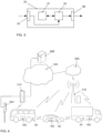
- Fig. 4 illustrates a basic architecture of a V2V (Vehicle-to-Vehicle) and V2X (Vehicle-to-Everything) communication system.
- Reference numeral 40 denotes vehicles, which in this example are a shuttle bus, a car, and a truck.
- the vehicles 40 are equipped with an on-board connectivity module 160 including a corresponding antenna such that the vehicles 40 can participate in any form of wireless communication service.
- the vehicles 40 may transmit and receive signals to and from a roadside unit 310 or a base station 210 of a mobile communication service provider.
- the roadside unit 310 and the base station 210 may be connected to a control center computer 320 via a network 300.
- a traffic light 340 connected to the roadside unit 310.
- the roadside unit 310 may transmit SPaT and MAP messages related to the traffic light 340 to the vehicles 40 via broadcast / direct communication.
- the vehicles 40 may also be equipped with means for observing their surroundings.
- Their sensor systems which are used to capture the environmental objects, are based on different measuring methods, depending on the application. Widespread technologies are, among others, RADAR, LIDAR, cameras for 2D and 3D image acquisition, and ultrasonic sensors.
- V2V and V2X communication need to be adapted correspondingly. They may make use of mobile communication technologies, such as LTE or 5G, wireless local area networks, or even optical communication technologies.
- Fig. 5 schematically shows an exemplary block diagram of a board electronics system of a vehicle.
- Part of the board electronics system is an infotainment system, which comprises a touch-sensitive display unit 50, a computing device 60, an input unit 70, and a memory device 80.
- the display unit 50 is connected to the computing device 60 via a data line 55 and includes both a display area for displaying variable graphical information and an operator interface (touch-sensitive layer) arranged above the display area for inputting commands by a user.
- the input unit 70 is connected to the computing device 60 via a data line 75.
- Reference numeral 71 designates a press button that allows a driver to manually request a tele-operated driving session if the vehicle is blocked and the driver wants the support of a tele-operated driving operator to find a way out of the blocking situation. There is no need for a dedicated press button 71 if other techniques for manual control are used. This includes selecting an option in a user menu displayed on the display unit 50, detecting the command with speech recognition, or using gesture control means.
- the memory device 80 is connected to the computing device 60 via a data line 85.
- a pictogram directory and/or symbol directory is deposited with pictograms and/or symbols for possible overlays of additional information.
- the other parts of the infotainment system such as a camera 150, radio 140, navigation device 130, telephone 120 and instrument cluster 110 are connected via a data bus 100 with the computing device 60.
- data bus 100 the high-speed variant of the CAN (Controller Area Network) bus according to ISO standard 11898-2 may be used.
- an Ethernet-based bus system such as IEEE 802.03cg can be used.
- Bus systems implementing the data transmission via optical fibers are also usable. Examples are the MOST Bus (Media Oriented System Transport) or the D2B Bus (Domestic Digital Bus).
- MOST Bus Media Oriented System Transport
- D2B Bus Domestic Digital Bus
- the vehicle is equipped with an on-board connectivity module 160. It can be used for mobile communication, e.g. mobile communication according to the 5G standard.
- Reference numeral 172 denotes an engine control unit.
- Reference numeral 174 denotes an ESC (electronic stability control) unit, whereas reference numeral 176 denotes a transmission control unit.
- Modern vehicles may comprise additional components, such as further sensors for scanning the surroundings, like a LIDAR sensor 186 or a RADAR sensor 182 and additional video cameras 151, e.g. a front camera, a rear camera or side cameras. Such sensors are increasingly used in vehicles for observation of the environment. Further control devices, such as an ADC (automatic driving control) unit 184, etc., may be provided in the vehicle.
- the RADAR and LIDAR sensors 182, 186 may have a scanning range of up to 250 m, whereas the cameras 150, 151 may cover a range from 30 m to 120 m.
- the components 182 to 186 are connected to another communication bus 102, e.g. an Ethernet-Bus due to its higher bandwidth for data transport.
- Ethernet-bus adapted to the special needs of car communication is standardized in the IEEE 802.1Q specification. Moreover, a lot of information about the environment may be received via V2V communication from other vehicles. Particularly for those vehicles that are not in line of sight to the observing vehicle, it is very advantageous to receive the information about their position and motion via V2V communication.
- Reference numeral 190 denotes an on-board diagnosis interface, which is connected to another communication bus 106.
- a gateway 90 For the purpose of transmitting the vehicle-relevant sensor data via the an on-board connectivity module 160 to another vehicle, to other infrastructure, or to a control center computer, a gateway 90 is provided.
- This gateway 90 is connected to the different bus systems 100, 102, 104 and 106.
- the gateway 90 is adapted to convert the data it receives via one bus to the transmission format of another bus so that it can be distributed using the packets specified for the respective other bus.
- the an on-board connectivity module 160 For forwarding this data to the outside, i.e. to another vehicle or to the control central computer, the an on-board connectivity module 160 is equipped with a communication interface to receive these data packets and, in turn, to convert them into the transmission format of the appropriate mobile radio standard.
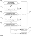
- Fig. 6 shows a preferred embodiment of a method for controlling operation of a vehicle equipped with an automated driving function. According to this preferred embodiment, several verification steps are performed. Depending on the respective verification results, either a decision is made to set the operation mode to normal operation or a decision is made to set the operation mode to a safe mode.
- a first verification step 400 the ego-localization of the vehicle is evaluated. In particular, it is checked if an ego-localization system of the vehicle delivers results with a required accuracy, e.g. sufficiently accurate to locate the vehicle on one of several lanes. If this is not the case, the operation mode is set to safe mode 450, in which the vehicle is brought into a safe condition, e.g. securely stopped. Otherwise, the method proceeds to the second verification step 410. In the second verification step 410, it is checked whether information obtained with environment sensors of the vehicle is in agreement with information from a highly detailed map available in the vehicle. If this is not the case, the operation mode is set to safe mode 450. Otherwise, the method proceeds to the third verification step 420.
- an ego-localization system of the vehicle delivers results with a required accuracy, e.g. sufficiently accurate to locate the vehicle on one of several lanes. If this is not the case, the operation mode is set to safe mode 450, in which the vehicle is brought into a safe condition, e.g. securely
- the information from the highly detailed map is compared with information retrieved from a MAP message. In particular, it is checked whether the information from the highly detailed map is in agreement with the information from the MAP message, e.g. with regard to the number and direction of the lanes. If this is not the case, the operation mode is set to safe mode 450. Otherwise, the method proceeds to the fourth verification step 430. In the fourth verification step 430, it is checked whether information retrieved from a SPaT message is in agreement with the information from the MAP message. If this is not the case, the operation mode is set to safe mode 450. Otherwise, the method proceeds to the fifth verification step 440.
- the fifth verification step 440 it is checked whether the signal state of the traffic light detected with the vehicle sensors is in agreement with the information from the SPaT message. If the signal states do not match, the operation mode is set to safe mode 450. If the signal states match, the operation mode is set to a normal operation mode 460 and the vehicle will continue its course once this is permitted by the traffic light. It may happen that no signal state can be detected with the vehicle sensors. For this situation, a fallback operation mode 470 may be defined, in which the vehicle accesses further sensor information or trusts the determined second signal state.
- Fig. 7 shows a vehicle 40 approaching a signalized intersection 330.
- Traffic is regulated using several traffic lights 340.
- a roadside unit 310 which may be connected to a control center computer 320 via a network 300, is provided for transmitting infrastructure related data to vehicles 40 in the vicinity of the intersection 330.
- the roadside unit 310 may likewise be connected to the traffic lights 340 without a connection to a control center computer 320.
- the roadside unit 310 receives the relevant information directly from a controller of the traffic lights 340 and transmits it to the vehicle 40 via broadcast / direct communication, e.g. as SPaT and MAP messages.
- the vehicle 40 is equipped with an automated driving function, e.g. of level 4 or 5.
- the automated driving function needs to respect all the traffic regulations, including traffic signs and traffic lights, etc. Instead of just relying on the data of the vehicle camera for determining the signal state of the relevant traffic light 340, the automated driving function additionally evaluates the SPaT and MAP messages provided by the roadside unit 310 as well as data of a highly detailed map and sensor data provided by further vehicle sensors, as described above with reference to Fig. 6 .
Landscapes
- Engineering & Computer Science (AREA)
- Physics & Mathematics (AREA)
- General Physics & Mathematics (AREA)
- Automation & Control Theory (AREA)
- Transportation (AREA)
- Mechanical Engineering (AREA)
- Human Computer Interaction (AREA)
- Life Sciences & Earth Sciences (AREA)
- Atmospheric Sciences (AREA)
- Multimedia (AREA)
- Computer Networks & Wireless Communication (AREA)
- Signal Processing (AREA)
- Theoretical Computer Science (AREA)
- Radar, Positioning & Navigation (AREA)
- Remote Sensing (AREA)
- Mathematical Physics (AREA)
- Traffic Control Systems (AREA)
Abstract
Description
- The present invention is related to a method, a computer program, and an apparatus for controlling operation of a vehicle equipped with an automated driving function. The invention is further related to a vehicle equipped with an automated driving function, which makes use of such a method or apparatus.
- Autonomous driving, also referred to as automatic driving, automated driving, or piloted driving, is the movement of vehicles, mobile robots and driverless transport systems that are largely autonomous. There are different degrees of autonomous driving. In Europe, various transport ministries, for example the Federal Institute for Road Systems (Bundesanstalt für Straßenwesen) in Germany, have defined the following autonomous stages:
- Level 0: "Driver only", the driver drives himself, steers, accelerates, brakes, etc.
- Level 1: Certain assistance systems help with vehicle operation, including a cruise control system such as ACC (Automatic Cruise Control).
- Level 2: Partial automation. Therein, automatic parking, tracking function, general longitudinal guidance, acceleration, deceleration, etc. are taken over by the assistance systems, including collision avoidance.
- Level 3: High automation. The driver does not have to monitor the system continuously. The vehicle independently performs functions such as the triggering of the turn signal, lane change and tracking. The driver can turn to other things, but if requested, the driver has to take over control within a pre-warning period.
- Level 4: Full automation. The guidance of the vehicle is permanently performed by the system. If the system is no longer able to handle the tasks, the driver can be asked to take over control.
- Level 5: No driver required. Apart from setting the target and starting the system, no human intervention is required.
- A slightly different definition of levels is known from the Society of Automotive Engineers (SAE). In this regard, reference is made to the SAE J3016 standard. Such definitions could also be used instead of the above given definition.
- In the field of autonomous driving, it is known to make use of map data as well as data of vehicle sensors in order to control operation of a vehicle. For example,
US 2019/0092291 A1 discloses a method for operating a vehicle relative to a passable object in a surrounding area of the vehicle. In accordance with the method, map data values from a map are input. The map data values include first object data values representing the passable object. In addition, second object data values representing the surrounding area, including the passable object, are recorded. The input map data values are reconciled with the second object data values in accordance with predefined first comparison criteria. The vehicle is then operated as a function of the reconciliation. - One task that needs to be performed for autonomous driving is the recognition of the signalization or signal state of traffic lights. This recognition is at present realized using cameras. However, with the currently available camera systems, recognizing the signal state may not be sufficiently safe for a vehicle that needs to autonomously enter an intersection with traffic lights.
- In this regard,
CN 106327897 A discloses a method for signaling a state of a traffic light on a display terminal of a vehicle. The traffic light generates signal phase and timing information and transmits this information to a roadside unit. The roadside unit publishes intersection position information, local MAP information and real-time SPaT information. A vehicle infrastructure communication module is used for information data interaction between a terminal device and the roadside unit. The terminal device is used for acquiring, processing and displaying vehicle motion state data and the state of the traffic light. - It is to be expected that the recognition of the signal states of traffic lights will need to fulfill the requirements of ASIL (Automotive Safety Integrity Level).
- These high safety requirements could mean that certain functions cannot be implemented in the vehicle.
- It is an object of the present invention to provide improved solutions for controlling operation of a vehicle equipped with an automated driving function.
- This object is achieved by a method according to claim 1, by a computer program according to
claim 11, which implements this method, and by an apparatus according toclaim 12. The dependent claims include advantageous further developments and improvements of the present principles as described below. - According to a first aspect, a method for controlling operation of a vehicle equipped with an automated driving function comprises the steps of:
- determining a first signal state of a traffic light from data of at least one vehicle sensor;
- validating the determined first signal state of the traffic light based on information available in the vehicle; and
- setting an operation mode of the vehicle as a function of a validation result.
- Accordingly, a computer program comprises instructions, which, when executed by at least one processor, cause the at least one processor to perform the following steps for controlling operation of a vehicle equipped with an automated driving function:
- determining a first signal state of a traffic light from data of at least one vehicle sensor;
- validating the determined first signal state of the traffic light based on information available in the vehicle; and
- setting an operation mode of the vehicle as a function of a validation result.
- The term computer has to be understood broadly. In particular, it also includes electronic control units, embedded devices and other processor-based data processing devices.
- The computer program code can, for example, be made available for electronic retrieval or stored on a computer-readable storage medium.
- According to another aspect, an apparatus for controlling operation of a vehicle equipped with an automated driving function comprises:
- an evaluation module configured to determine a first signal state of a traffic light from data of at least one vehicle sensor;
- a validation module configured to validate the determined first signal state of the traffic light based on information available in the vehicle; and
- a mode setting module configured to set an operation mode of the vehicle as a function of a validation result.
- According to the invention, instead of trying to adapt the camera-based recognition of the signal state in such way that it fulfills the high safety requirements, the safety requirements are shifted to other components of the vehicle. For this purpose, such components of the vehicle are selected, which can easily fulfill high safety requirements. Information of these components is then used to validate the determined signal state.
- In an advantageous embodiment, a second signal state of the traffic light is determined from a SPaT message received from a communication infrastructure. The determined first signal state of the traffic light is then validated by comparing the first signal state and the second signal state. A SPaT message describes the current phase at a signalized intersection, together with the residual time of the phase, for every lane of the intersection. By using a redundant system for determining the signal state of the traffic light, the overall reliability of signal state recognition is increased. Preferably, the operation mode is set to a normal operation mode in case the first signal state and the second signal state match, to a safe mode in case the first signal state and the second signal state do not match, and to a fallback mode in case no first signal state can be determined. When both determined signal states match, this is a strong indication that the first signal state has been determined correctly and normal operation is possible. When both determined signal states conflict, this is a strong indication that the first signal state may not have been determined correctly. In this case, it is advisable to make use of a safe mode. In case no first signal state can be determined, the automated driving function needs to rely on the information of the SPaT message. In this case, it is advisable to enter a fallback mode, in which the vehicle accesses further sensor information, e.g. information related to the behavior of the surrounding traffic. For example, the vehicle may know that it is located on one of two straight-ahead lanes, but it is unsure if the traffic light shows green. If in this situation a vehicle in the second / parallel lane enters the intersection, it could cross the intersection a little bit slower or with a slight delay. Another possibility is that if the vehicle knows from map data that it is located at a traffic light which sends secured signals, e.g. SPaT and MAP messages, it may trust these signals and slowly pass the intersection, preferably in combination with a sensor detection of cross-traffic.
- In an advantageous embodiment, the determined first signal state of the traffic light is validated by determining if an ego-localization system of the vehicle delivers results with a required accuracy, wherein the operation mode is set to a safe mode when this is not the case. Vehicles with an automated driving function necessarily have an ego-localization system. Such a system will typically be able to perform a self-diagnosis, which can be used to evaluate the accuracy of the system. In case the results of the ego-localization are sufficiently accurate, it may be impossible to determine on which lane of a road with multiple lanes the vehicle is located. As a consequence, the determined first signal state may actually refer to different lane and it is not safe to continue normal operation.
- In an advantageous embodiment, the determined first signal state of the traffic light is validated by determining if information obtained with environment sensors of the vehicle is in agreement with information from a highly detailed map available in the vehicle, wherein the operation mode is set to a safe mode when this is not the case. In order to facilitate the camera-based detection and evaluation of traffic lights, the positions of traffic lights can be included in a highly detailed map available in the vehicle, as this allows reducing the search space of the camera. Current discussions place requirements on these map entries from a perspective of functional safety. In case there is a conflict between the information obtained with the environment sensors and the information from the highly detailed map, this is a strong indication that either the highly detailed map is not accurate or outdated or that the environment sensors deliver incorrect data. In both cases, it is not safe to continue normal operation.
- In an advantageous embodiment, the determined first signal state of the traffic light is validated by determining if information from a highly detailed map available in the vehicle is in agreement with information from a MAP message received from a communication infrastructure, wherein the operation mode is set to a safe mode when this is not the case. A SPaT message is generally used together with a MAP message, which describes the physical geometry of one or more intersections. Generic facilities and infrastructure-centric messaging, such as SPaT and MAP messaging, are developed in ISO/TC 204/WG 18 jointly with CEN/TC 278/WG 16. In case there is a conflict between the information from the MAP message and the information from the highly detailed map, this is an indication that the highly detailed map is not accurate or outdated. As a consequence, it is not safe to rely on the highly detailed map for detecting and evaluating traffic lights and to continue normal operation.
- In an advantageous embodiment, the determined first signal state of the traffic light is validated by determining if information from a SPaT message received from a communication infrastructure is in agreement with information from a MAP message received from the communication infrastructure, wherein the operation mode is set to a safe mode when this is not the case. In case there is a conflict between the information from the SPaT message and the information from the MAP message, this is a strong indication that at least one of those messages is not correct. As a consequence, it is not safe to rely on the information from the SPaT message to determine the signal state and to continue normal operation.
- In an advantageous embodiment, in the safe mode the vehicle is brought into a safe condition. For example, the vehicle may be securely stopped. This ensures that the vehicle does not perform any action that may cause harm to the surrounding traffic.
- Advantageously, a vehicle equipped with an automated driving function comprises an apparatus according to the invention or is configured to perform a method according to the invention for controlling operation of the vehicle. In this way, the vehicle is able to fulfill the high safety requirements of the recognition of the signal states of traffic lights. The vehicle may be any type of vehicle, e.g. a car, a bus, a motorcycle, a commercial vehicle, in particular a truck, an agricultural machinery, a construction machinery, a rail vehicle, etc. More generally, the invention can be used in all vehicles that need to cope with traffic lights.
- Further features of the present invention will become apparent from the following description and the appended claims in conjunction with the figures.
- Fig. 1
- schematically illustrates a method for controlling operation of a vehicle equipped with an automated driving function;
- Fig. 2
- schematically illustrates a first embodiment of an apparatus for controlling operation of a vehicle equipped with an automated driving function;
- Fig. 3
- schematically illustrates a second embodiment of an apparatus for controlling operation of a vehicle equipped with an automated driving function;
- Fig. 4
- illustrates a basic architecture of a V2V and V2X communication system;
- Fig. 5
- shows a block diagram of an electronics system of a vehicle;
- Fig. 6
- shows a preferred embodiment of a method for controlling operation of a vehicle equipped with an automated driving function; and
- Fig. 7
- shows a vehicle approaching a signalized intersection.
- The present description illustrates the principles of the present disclosure. It will thus be appreciated that those skilled in the art will be able to devise various arrangements that, although not explicitly described or shown herein, embody the principles of the disclosure.
- All examples and conditional language recited herein are intended for educational purposes to aid the reader in understanding the principles of the disclosure and the concepts contributed by the inventor to furthering the art, and are to be construed as being without limitation to such specifically recited examples and conditions.
- Moreover, all statements herein reciting principles, aspects, and embodiments of the disclosure, as well as specific examples thereof, are intended to encompass both structural and functional equivalents thereof. Additionally, it is intended that such equivalents include both currently known equivalents as well as equivalents developed in the future, i.e., any elements developed that perform the same function, regardless of structure.
- Thus, for example, it will be appreciated by those skilled in the art that the diagrams presented herein represent conceptual views of illustrative circuitry embodying the principles of the disclosure.
- The functions of the various elements shown in the figures may be provided through the use of dedicated hardware as well as hardware capable of executing software in association with appropriate software. When provided by a processor, the functions may be provided by a single dedicated processor, by a single shared processor, or by a plurality of individual processors, some of which may be shared. Moreover, explicit use of the term "processor" or "controller" should not be construed to refer exclusively to hardware capable of executing software, and may implicitly include, without limitation, digital signal processor (DSP) hardware, read only memory (ROM) for storing software, random access memory (RAM), and nonvolatile storage.
- Other hardware, conventional and/or custom, may also be included. Similarly, any switches shown in the figures are conceptual only. Their function may be carried out through the operation of program logic, through dedicated logic, through the interaction of program control and dedicated logic, or even manually, the particular technique being selectable by the implementer as more specifically understood from the context.
- In the claims hereof, any element expressed as a means for performing a specified function is intended to encompass any way of performing that function including, for example, a combination of circuit elements that performs that function or software in any form, including, therefore, firmware, microcode or the like, combined with appropriate circuitry for executing that software to perform the function. The disclosure as defined by such claims resides in the fact that the functionalities provided by the various recited means are combined and brought together in the manner which the claims call for. It is thus regarded that any means that can provide those functionalities are equivalent to those shown herein.
-
Fig. 1 schematically illustrates a method according to the invention for controlling operation of a vehicle equipped with an automated driving function. In a first step, a first signal state of a traffic light is determined 11 from data of at least one vehicle sensor. The determined first signal state of the traffic light is then validated 12 based on information available in the vehicle. For this purpose, a second signal state may be determined from a SPaT message received from a communication infrastructure. The first signal state may then be validated by comparing the first signal state and the second signal state. Furthermore, the first signal state may be validated by determining if an ego-localization system of the vehicle delivers results with a required accuracy, by determining if information obtained with environment sensors of the vehicle is in agreement with information from a highly detailed map available in the vehicle, by determining if information from the highly detailed map is in agreement with information from a MAP message received from the communication infrastructure, or by determining if information from the SPaT message is in agreement with information from the MAP message. Of course, also combinations of these validation measures may be used. Finally, an operation mode of the vehicle is set 13 as a function of a validation result. Preferably, the operation mode may be set to a safe mode in case any of the validation measures delivers a negative result. In the safe mode, the vehicle may be brought into a safe condition. If all validation measures deliver a positive result, the operation mode may be set to a normal operation mode. In case no second signal state may be determined from the data of the at least one vehicle sensor, the operation mode may be set to a fallback mode, in which the vehicle accesses further sensor information or trusts the determined second signal state. -
Fig. 2 schematically illustrates a block diagram of a first embodiment of anapparatus 20 according to the invention for controlling operation of a vehicle equipped with an automated driving function. Theapparatus 20 has aninput 21 for receiving data, e.g. messages M1, M2 from acommunication infrastructure 310, sensor data SD of at least onevehicle sensor 151 or further information INF available in the vehicle. Anevaluation module 22 is configured to determine a first signal state Ss of a traffic light from the sensor data SD. In addition, theevaluation module 22 may determine a second signal state SM from a SPaT message received from thecommunication infrastructure 310. Avalidation module 23 is configured to validate the determined first signal state Ss of the traffic light based on the information INF available in the vehicle. For example, thevalidation module 23 may validate the first signal state SS by comparing the first signal state SS and the second signal state SM, by determining if an ego-localization system of the vehicle delivers results with a required accuracy, by determining if information obtained with environment sensors of the vehicle is in agreement with information from a highly detailed map available in the vehicle, by determining if information from the highly detailed map is in agreement with information from a MAP message received from the communication infrastructure, or by determining if information from the SPaT message is in agreement with information from the MAP message. Of course, also combinations of these validation measures may be used. Amode setting module 24 is configured to set an operation mode of the vehicle as a function of a validation result. Preferably, themode setting module 24 may set the operation mode to a safe mode in case any of the validation measures delivers a negative result. In the safe mode, the vehicle may be brought into a safe condition. If all validation measures deliver a positive result, themode setting module 24 may set the operation mode to a normal operation mode. In case no second signal state Ss may be determined from the sensor data SD, the operation mode may be set to a fallback mode, in which the vehicle accesses further sensor information or trusts the determined second signal state. For setting the operation mode, themode setting module 24 may generate a mode signal M, which may be provided to an automaticdriving control unit 184 via anoutput 27. Alocal storage unit 26 is provided, e.g. for storing data during processing. Theoutput 27 may also be combined with theinput 21 into a single bidirectional interface. - The
evaluation module 22, thevalidation module 23, and themode setting module 24 may be controlled by acontroller 25. Auser interface 28 may be provided for enabling a user to modify settings of theevaluation module 22, thevalidation module 23, themode setting module 24, or thecontroller 25. Theevaluation module 22, thevalidation module 23, themode setting module 24, and thecontroller 25 can be embodied as dedicated hardware units. Of course, they may likewise be fully or partially combined into a single unit or implemented as software running on a processor, e.g. a CPU or a GPU. - A block diagram of a second embodiment of an
apparatus 30 according to the invention for controlling operation of a vehicle equipped with an automated driving function is illustrated inFig. 3 . Theapparatus 30 comprises aprocessing device 31 and amemory device 32. For example, theapparatus 30 may be a computer, an electronic control unit or an embedded system. Thememory device 32 has stored instructions that, when executed by theprocessing device 31, cause theapparatus 30 to perform steps according to one of the described methods. The instructions stored in thememory device 32 thus tangibly embody a program of instructions executable by theprocessing device 31 to perform program steps as described herein according to the present principles. Theapparatus 30 has aninput 33 for receiving data. Data generated by theprocessing device 31 are made available via anoutput 34. In addition, such data may be stored in thememory device 32. Theinput 33 and theoutput 34 may be combined into a single bidirectional interface. - The
processing device 31 as used herein may include one or more processing units, such as microprocessors, digital signal processors, or a combination thereof. - The
local storage unit 26 and thememory device 32 may include volatile and/or non-volatile memory regions and storage devices such as hard disk drives, optical drives, and/or solid-state memories. - In the following, a preferred embodiment of the invention shall be explained in more detail with reference to
Fig. 4 to Fig. 7 . -
Fig. 4 illustrates a basic architecture of a V2V (Vehicle-to-Vehicle) and V2X (Vehicle-to-Everything) communication system.Reference numeral 40 denotes vehicles, which in this example are a shuttle bus, a car, and a truck. Thevehicles 40 are equipped with an on-board connectivity module 160 including a corresponding antenna such that thevehicles 40 can participate in any form of wireless communication service. As shown inFig. 4 , thevehicles 40 may transmit and receive signals to and from aroadside unit 310 or abase station 210 of a mobile communication service provider. Theroadside unit 310 and thebase station 210 may be connected to acontrol center computer 320 via anetwork 300. Also shown is atraffic light 340 connected to theroadside unit 310. Theroadside unit 310 may transmit SPaT and MAP messages related to thetraffic light 340 to thevehicles 40 via broadcast / direct communication. - The
vehicles 40 may also be equipped with means for observing their surroundings. Their sensor systems, which are used to capture the environmental objects, are based on different measuring methods, depending on the application. Widespread technologies are, among others, RADAR, LIDAR, cameras for 2D and 3D image acquisition, and ultrasonic sensors. - Since automated driving is on the rise, a lot more data needs to be exchanged among the
vehicles 40, e.g. using V2V communication, and also between thevehicles 40 and the network. The communication systems for V2V and V2X communication need to be adapted correspondingly. They may make use of mobile communication technologies, such as LTE or 5G, wireless local area networks, or even optical communication technologies. -
Fig. 5 schematically shows an exemplary block diagram of a board electronics system of a vehicle. Part of the board electronics system is an infotainment system, which comprises a touch-sensitive display unit 50, acomputing device 60, aninput unit 70, and amemory device 80. Thedisplay unit 50 is connected to thecomputing device 60 via adata line 55 and includes both a display area for displaying variable graphical information and an operator interface (touch-sensitive layer) arranged above the display area for inputting commands by a user. Theinput unit 70 is connected to thecomputing device 60 via adata line 75.Reference numeral 71 designates a press button that allows a driver to manually request a tele-operated driving session if the vehicle is blocked and the driver wants the support of a tele-operated driving operator to find a way out of the blocking situation. There is no need for adedicated press button 71 if other techniques for manual control are used. This includes selecting an option in a user menu displayed on thedisplay unit 50, detecting the command with speech recognition, or using gesture control means. - The
memory device 80 is connected to thecomputing device 60 via adata line 85. In thememory device 80, a pictogram directory and/or symbol directory is deposited with pictograms and/or symbols for possible overlays of additional information. - The other parts of the infotainment system, such as a
camera 150,radio 140,navigation device 130,telephone 120 andinstrument cluster 110 are connected via adata bus 100 with thecomputing device 60. Asdata bus 100, the high-speed variant of the CAN (Controller Area Network) bus according to ISO standard 11898-2 may be used. Alternatively, an Ethernet-based bus system such as IEEE 802.03cg can be used. Bus systems implementing the data transmission via optical fibers are also usable. Examples are the MOST Bus (Media Oriented System Transport) or the D2B Bus (Domestic Digital Bus). For inbound and outbound wireless communication, the vehicle is equipped with an on-board connectivity module 160. It can be used for mobile communication, e.g. mobile communication according to the 5G standard. -
Reference numeral 172 denotes an engine control unit.Reference numeral 174 denotes an ESC (electronic stability control) unit, whereasreference numeral 176 denotes a transmission control unit. The networking of such control units, all of which are allocated to the category of the drive train, typically occurs with aCAN bus 104. Since various sensors are installed in the vehicle and these are no longer only connected to individual control units, such sensor data are also distributed via thebus system 104 to the individual control devices. - Modern vehicles may comprise additional components, such as further sensors for scanning the surroundings, like a
LIDAR sensor 186 or aRADAR sensor 182 andadditional video cameras 151, e.g. a front camera, a rear camera or side cameras. Such sensors are increasingly used in vehicles for observation of the environment. Further control devices, such as an ADC (automatic driving control)unit 184, etc., may be provided in the vehicle. The RADAR andLIDAR sensors cameras components 182 to 186 are connected to anothercommunication bus 102, e.g. an Ethernet-Bus due to its higher bandwidth for data transport. One Ethernet-bus adapted to the special needs of car communication is standardized in the IEEE 802.1Q specification. Moreover, a lot of information about the environment may be received via V2V communication from other vehicles. Particularly for those vehicles that are not in line of sight to the observing vehicle, it is very advantageous to receive the information about their position and motion via V2V communication. -
Reference numeral 190 denotes an on-board diagnosis interface, which is connected to anothercommunication bus 106. - For the purpose of transmitting the vehicle-relevant sensor data via the an on-
board connectivity module 160 to another vehicle, to other infrastructure, or to a control center computer, agateway 90 is provided. Thisgateway 90 is connected to thedifferent bus systems gateway 90 is adapted to convert the data it receives via one bus to the transmission format of another bus so that it can be distributed using the packets specified for the respective other bus. For forwarding this data to the outside, i.e. to another vehicle or to the control central computer, the an on-board connectivity module 160 is equipped with a communication interface to receive these data packets and, in turn, to convert them into the transmission format of the appropriate mobile radio standard. -
Fig. 6 shows a preferred embodiment of a method for controlling operation of a vehicle equipped with an automated driving function. According to this preferred embodiment, several verification steps are performed. Depending on the respective verification results, either a decision is made to set the operation mode to normal operation or a decision is made to set the operation mode to a safe mode. - In a
first verification step 400, the ego-localization of the vehicle is evaluated. In particular, it is checked if an ego-localization system of the vehicle delivers results with a required accuracy, e.g. sufficiently accurate to locate the vehicle on one of several lanes. If this is not the case, the operation mode is set tosafe mode 450, in which the vehicle is brought into a safe condition, e.g. securely stopped. Otherwise, the method proceeds to thesecond verification step 410. In thesecond verification step 410, it is checked whether information obtained with environment sensors of the vehicle is in agreement with information from a highly detailed map available in the vehicle. If this is not the case, the operation mode is set tosafe mode 450. Otherwise, the method proceeds to thethird verification step 420. In thethird verification step 420, the information from the highly detailed map is compared with information retrieved from a MAP message. In particular, it is checked whether the information from the highly detailed map is in agreement with the information from the MAP message, e.g. with regard to the number and direction of the lanes. If this is not the case, the operation mode is set tosafe mode 450. Otherwise, the method proceeds to thefourth verification step 430. In thefourth verification step 430, it is checked whether information retrieved from a SPaT message is in agreement with the information from the MAP message. If this is not the case, the operation mode is set tosafe mode 450. Otherwise, the method proceeds to thefifth verification step 440. In thefifth verification step 440, it is checked whether the signal state of the traffic light detected with the vehicle sensors is in agreement with the information from the SPaT message. If the signal states do not match, the operation mode is set tosafe mode 450. If the signal states match, the operation mode is set to anormal operation mode 460 and the vehicle will continue its course once this is permitted by the traffic light. It may happen that no signal state can be detected with the vehicle sensors. For this situation, afallback operation mode 470 may be defined, in which the vehicle accesses further sensor information or trusts the determined second signal state. -
Fig. 7 shows avehicle 40 approaching asignalized intersection 330. Traffic is regulated usingseveral traffic lights 340. Aroadside unit 310, which may be connected to acontrol center computer 320 via anetwork 300, is provided for transmitting infrastructure related data tovehicles 40 in the vicinity of theintersection 330. Theroadside unit 310 may likewise be connected to thetraffic lights 340 without a connection to acontrol center computer 320. In this case, theroadside unit 310 receives the relevant information directly from a controller of thetraffic lights 340 and transmits it to thevehicle 40 via broadcast / direct communication, e.g. as SPaT and MAP messages. Thevehicle 40 is equipped with an automated driving function, e.g. of level 4 or 5. The automated driving function needs to respect all the traffic regulations, including traffic signs and traffic lights, etc. Instead of just relying on the data of the vehicle camera for determining the signal state of therelevant traffic light 340, the automated driving function additionally evaluates the SPaT and MAP messages provided by theroadside unit 310 as well as data of a highly detailed map and sensor data provided by further vehicle sensors, as described above with reference toFig. 6 . -
- 10
- Receive messages from communication infrastructure
- 11
- Determine signal state of traffic light
- 12
- Validate determined signal state
- 13
- Set operation mode as function of validation result
- 20
- Apparatus
- 21
- Input
- 22
- Evaluation module
- 23
- Validation module
- 24
- Mode setting module
- 25
- Controller
- 26
- Local storage unit
- 27
- Output
- 28
- User interface
- 30
- Apparatus
- 31
- Processing device
- 32
- Memory device
- 33
- Input
- 34
- Output
- 40
- Vehicle
- 50
- Display Unit
- 55
- Data line to display unit
- 60
- Computing device
- 70
- Input unit
- 71
- Press button
- 75
- Data line to input unit
- 80
- Memory unit
- 85
- Data line to memory unit
- 90
- Gateway
- 100
- First data bus
- 102
- Second data bus
- 104
- Third data bus
- 106
- Fourth data bus
- 110
- Instrument cluster
- 120
- Telephone
- 130
- Navigation device
- 140
- Radio
- 150
- Camera
- 151
- Further cameras
- 160
- On-board connectivity module
- 172
- Engine control unit
- 174
- Electronic stability control unit
- 176
- Transmission control unit
- 182
- RADAR sensor
- 184
- Automatic driving control unit
- 186
- LI DAR sensor
- 190
- On-board diagnosis interface
- 210
- Base station
- 300
- Network
- 310
- Roadside unit
- 320
- Control center computer
- 330
- Intersection
- 340
- Traffic light
- 400
- First verification step
- 410
- Second verification step
- 420
- Third verification step
- 430
- Fourth verification step
- 440
- Fifth verification step
- 450
- Safe mode
- 460
- Normal operation
- 470
- Fallback operation
- INF
- Information
- M
- Mode signal
- M1, M2
- Message
- SD
- Sensor data
- SM, SS
- Signal state
Claims (13)
- A method for controlling operation of a vehicle (40) equipped with an automated driving function, the method comprising:- determining (11) a first signal state (SS) of a traffic light (340) from data (SD) of at least one vehicle sensor (151);- validating (12) the determined first signal state (SS) of the traffic light (340) based on information available in the vehicle (40); and- setting (13) an operation mode of the vehicle (40) as a function of a validation result.
- The method according to claim 1, wherein a second signal state (SM) of the traffic light (340) is determined (11) from a SPaT message (M1) received (10) from a communication infrastructure (310).
- The method according to claim 2, wherein the determined first signal state (SS) of the traffic light (340) is validated (12) by comparing the first signal state (SS) and the second signal state(SM).
- The method according to claim 3, wherein the operation mode is set to a normal operation mode (460) in case the first signal state (SS) and the second signal state (SM) match, to a safe mode (450) in case the first signal state (SS) and the second signal state (SM) do not match, and to a fallback mode (470) in case no first signal state (SS) can be determined (11).
- The method according to claim 4, wherein in the fallback mode (470) the vehicle (40) accesses further sensor information or trusts the determined second signal state.
- The method according to one of the preceding claims, wherein the determined first signal state (SS) of the traffic light (340) is validated (12) by determining if an ego-localization system of the vehicle (40) delivers results with a required accuracy, wherein the operation mode is set (13) to a safe mode (450) when this is not the case.
- The method according to one of the preceding claims, wherein the determined first signal state (SS) of the traffic light (340) is validated (12) by determining if information obtained with environment sensors of the vehicle (40) is in agreement with information from a highly detailed map available in the vehicle (40), wherein the operation mode is set (13) to a safe mode (450) when this is not the case.
- The method according to one of the preceding claims, wherein the determined first signal state (SS) of the traffic light (340) is validated (12) by determining if information from a highly detailed map available in the vehicle (40) is in agreement with information from a MAP message (M2) received (10) from a communication infrastructure (310), wherein the operation mode is set (13) to a safe mode (450) when this is not the case.
- The method according to one of the preceding claims, wherein the determined first signal state (SS) of the traffic light (340) is validated (12) by determining if information from a SPaT message (M1) received (10) from a communication infrastructure (310) is in agreement with information from a MAP message (M2) received (10) from the communication infrastructure (310), wherein the operation mode is set (13) to a safe mode (450) when this is not the case.
- The method according to one of claims 4 to 9, wherein in the safe mode (450) the vehicle (40) is brought into a safe condition.
- A computer program comprising instructions, which, when executed by a computer, cause the computer to perform a method according to any of claims 1 to 10 for controlling operation of a vehicle (40) equipped with an automated driving function.
- An apparatus (20) for controlling operation of a vehicle (40) equipped with an automated driving function, the apparatus (20) comprising:- an evaluation module (22) configured to determine (11) a first signal state (SS) of a traffic light (340) from data (SD) of at least one vehicle sensor (151);- a validation module (23) configured to validate (12) the determined first signal state (SS) of the traffic light (340) based on information available in the vehicle (40); and- a mode setting module (24) configured to set (13) an operation mode of the vehicle (40) as a function of a validation result.
- A vehicle (40) equipped with an automated driving function, characterized in that the vehicle (40) comprises an apparatus (20) according to claim 12 or is configured to perform a method according to any of claims 1 to 10 for controlling operation of the vehicle (40).
Priority Applications (3)
| Application Number | Priority Date | Filing Date | Title |
|---|---|---|---|
| EP20196200.8A EP3968305B1 (en) | 2020-09-15 | 2020-09-15 | Method, computer program and apparatus for controlling operation of a vehicle equipped with an automated driving function |
| US17/474,881 US11904898B2 (en) | 2020-09-15 | 2021-09-14 | Method, computer program and apparatus for controlling operation of a vehicle equipped with an automated driving function |
| CN202111079707.2A CN114179822B (en) | 2020-09-15 | 2021-09-15 | Method, computer program and apparatus for controlling the operation of a vehicle equipped with automated driving functions |
Applications Claiming Priority (1)
| Application Number | Priority Date | Filing Date | Title |
|---|---|---|---|
| EP20196200.8A EP3968305B1 (en) | 2020-09-15 | 2020-09-15 | Method, computer program and apparatus for controlling operation of a vehicle equipped with an automated driving function |
Publications (2)
| Publication Number | Publication Date |
|---|---|
| EP3968305A1 true EP3968305A1 (en) | 2022-03-16 |
| EP3968305B1 EP3968305B1 (en) | 2025-09-03 |
Family
ID=72560324
Family Applications (1)
| Application Number | Title | Priority Date | Filing Date |
|---|---|---|---|
| EP20196200.8A Active EP3968305B1 (en) | 2020-09-15 | 2020-09-15 | Method, computer program and apparatus for controlling operation of a vehicle equipped with an automated driving function |
Country Status (3)
| Country | Link |
|---|---|
| US (1) | US11904898B2 (en) |
| EP (1) | EP3968305B1 (en) |
| CN (1) | CN114179822B (en) |
Families Citing this family (8)
| Publication number | Priority date | Publication date | Assignee | Title |
|---|---|---|---|---|
| DE102019119084A1 (en) * | 2019-07-15 | 2021-01-21 | Valeo Schalter Und Sensoren Gmbh | Determining a signal status of a traffic light system |
| KR102335372B1 (en) * | 2020-10-19 | 2021-12-06 | 주식회사 오비고 | Method and monitoring server for verifying the operation of autonomous vehicles using THE Quality Control verification app |
| KR20220083945A (en) * | 2020-12-11 | 2022-06-21 | 현대자동차주식회사 | Apparatus for providing traffic light, system having the same and method thereof |
| JP2022134361A (en) * | 2021-03-03 | 2022-09-15 | 本田技研工業株式会社 | Information transmission system |
| US20230199493A1 (en) * | 2021-12-21 | 2023-06-22 | Continental Automotive Systems, Inc. | System and method for determining v2x message integrity |
| TWI842092B (en) * | 2022-09-15 | 2024-05-11 | 財團法人工業技術研究院 | Dual-core redundant control system for agricultural machinery |
| DE102024203107A1 (en) | 2024-04-04 | 2025-10-09 | Robert Bosch Gesellschaft mit beschränkter Haftung | Method for operating an electronic traffic signaling device and for operating a motor vehicle |
| US12459535B1 (en) * | 2024-12-26 | 2025-11-04 | Aurora Operations, Inc. | Autonomous vehicle anomalous event detection |
Citations (4)
| Publication number | Priority date | Publication date | Assignee | Title |
|---|---|---|---|---|
| CN106327897A (en) | 2016-09-07 | 2017-01-11 | 重庆云途交通科技有限公司 | Signal lamp state terminal display method and system based on cooperative vehicle infrastructure technology |
| US20190018408A1 (en) * | 2017-07-12 | 2019-01-17 | Qualcomm Incorporated | Systems and methods for verifying integrity of a sensing system |
| US20190092291A1 (en) | 2016-04-29 | 2019-03-28 | Robert Bosch Gmbh | Method and device for a motor vehicle for comparing surrounding area map data to surrounding area sensor data to determine the passability of a road object |
| US20200004268A1 (en) * | 2019-07-31 | 2020-01-02 | Lg Electronics Inc. | Method and apparatus for determining validity of message received by vehicle in automated vehicle & highway systems |
Family Cites Families (20)
| Publication number | Priority date | Publication date | Assignee | Title |
|---|---|---|---|---|
| US9145140B2 (en) * | 2012-03-26 | 2015-09-29 | Google Inc. | Robust method for detecting traffic signals and their associated states |
| US8761991B1 (en) * | 2012-04-09 | 2014-06-24 | Google Inc. | Use of uncertainty regarding observations of traffic intersections to modify behavior of a vehicle |
| US9881220B2 (en) * | 2013-10-25 | 2018-01-30 | Magna Electronics Inc. | Vehicle vision system utilizing communication system |
| DE102015016349B4 (en) * | 2015-10-07 | 2023-02-23 | Volkswagen Aktiengesellschaft | Device and method for a driver assistance system for a vehicle and device and method for a control instance for a controllable traffic sign |
| DE112015007060T5 (en) * | 2015-10-28 | 2018-07-12 | Volkswagen Aktiengesellschaft | Control method, control device and control system |
| KR101951035B1 (en) * | 2016-01-29 | 2019-05-10 | 한국전자통신연구원 | Self-driving system and method of vehicle |
| US10300894B2 (en) * | 2017-03-13 | 2019-05-28 | Denso International America, Inc. | Auto-braking system for vehicle and method for auto-braking vehicle |
| US20180315314A1 (en) * | 2017-04-28 | 2018-11-01 | GM Global Technology Operations LLC | Automated vehicle route traversal |
| FR3068944B1 (en) * | 2017-07-12 | 2019-07-19 | Psa Automobiles Sa | METHOD AND SYSTEM FOR ASSISTING THE DRIVING OF AN AUTONOMOUS VEHICLE ON A CIRCULATION PATH HAVING OBLIGED PASSAGE AREAS |
| CN107831789A (en) * | 2017-12-12 | 2018-03-23 | 成都育芽科技有限公司 | A kind of unmanned automatic driving mechanical transport signal lamp synchronisation control means |
| US11334753B2 (en) * | 2018-04-30 | 2022-05-17 | Uatc, Llc | Traffic signal state classification for autonomous vehicles |
| CN109263659A (en) * | 2018-07-28 | 2019-01-25 | 上海商汤智能科技有限公司 | Intelligent driving control method and device, vehicle, electronic equipment, medium, product |
| DE102018217932A1 (en) * | 2018-10-19 | 2020-04-23 | Robert Bosch Gmbh | Method and device for operating an automated vehicle |
| DE112020002604T5 (en) * | 2019-05-29 | 2022-03-03 | Mobileye Vision Technologies Ltd. | SYSTEMS AND PROCEDURES FOR VEHICLE NAVIGATION |
| US11988518B2 (en) * | 2019-06-17 | 2024-05-21 | Nvidia Corporation | Updating high definition maps based on lane closure and lane opening |
| CN111292531B (en) * | 2020-02-06 | 2022-07-29 | 阿波罗智能技术(北京)有限公司 | Tracking method, device and equipment of traffic signal lamp and storage medium |
| US11854212B2 (en) * | 2020-02-26 | 2023-12-26 | Motional Ad Llc | Traffic light detection system for vehicle |
| US11866068B2 (en) * | 2020-06-19 | 2024-01-09 | Waymo Llc | Detecting and responding to malfunctioning traffic signals for autonomous vehicles |
| JP7409257B2 (en) * | 2020-08-07 | 2024-01-09 | 株式会社デンソー | Traffic light recognition device, traffic light recognition method, vehicle control device |
| CN112818853B (en) * | 2021-02-01 | 2022-07-19 | 中国第一汽车股份有限公司 | Traffic element identification method, device, equipment and storage medium |
-
2020
- 2020-09-15 EP EP20196200.8A patent/EP3968305B1/en active Active
-
2021
- 2021-09-14 US US17/474,881 patent/US11904898B2/en active Active
- 2021-09-15 CN CN202111079707.2A patent/CN114179822B/en active Active
Patent Citations (4)
| Publication number | Priority date | Publication date | Assignee | Title |
|---|---|---|---|---|
| US20190092291A1 (en) | 2016-04-29 | 2019-03-28 | Robert Bosch Gmbh | Method and device for a motor vehicle for comparing surrounding area map data to surrounding area sensor data to determine the passability of a road object |
| CN106327897A (en) | 2016-09-07 | 2017-01-11 | 重庆云途交通科技有限公司 | Signal lamp state terminal display method and system based on cooperative vehicle infrastructure technology |
| US20190018408A1 (en) * | 2017-07-12 | 2019-01-17 | Qualcomm Incorporated | Systems and methods for verifying integrity of a sensing system |
| US20200004268A1 (en) * | 2019-07-31 | 2020-01-02 | Lg Electronics Inc. | Method and apparatus for determining validity of message received by vehicle in automated vehicle & highway systems |
Also Published As
| Publication number | Publication date |
|---|---|
| US20220081011A1 (en) | 2022-03-17 |
| CN114179822A (en) | 2022-03-15 |
| CN114179822B (en) | 2024-10-15 |
| US11904898B2 (en) | 2024-02-20 |
| EP3968305B1 (en) | 2025-09-03 |
Similar Documents
| Publication | Publication Date | Title |
|---|---|---|
| EP3968305B1 (en) | Method, computer program and apparatus for controlling operation of a vehicle equipped with an automated driving function | |
| CN104240535B (en) | The method coordinated for the operation to motor vehicle | |
| US11532097B2 (en) | Method for estimating the quality of localization in the self-localization of a vehicle, device for carrying out the steps of the method, vehicle, and computer program | |
| CN106515738B (en) | Lane change engagement | |
| JP2019207700A (en) | Driving control device, driving control method, and inter-vehicle communication system | |
| US20200257282A1 (en) | Vehicle control arbitration | |
| US11829134B2 (en) | Display control device and display control method | |
| US11960280B2 (en) | Display control device and display control method | |
| US11989018B2 (en) | Remote operation device and remote operation method | |
| JP2020095481A (en) | Control device of vehicle and automatic driving system | |
| CN115092126B (en) | Vehicle control device, vehicle control method and computer-readable storage medium | |
| US20200118433A1 (en) | Drive assistance system | |
| EP3893073B1 (en) | Method and apparatus for invoking a tele-operated driving session | |
| CN118046896A (en) | Driving assistance devices | |
| CN116206476A (en) | Method and system for operating an estimation of a design domain boundary | |
| CN104590255A (en) | Method for operating a vehicle | |
| JP7400710B2 (en) | Vehicle control system and vehicle control method | |
| US12151695B2 (en) | Control device and control method | |
| US11830257B2 (en) | Method, apparatus, and non-transitory computer readable storage medium for confirming a perceived position of a traffic light | |
| WO2023013341A1 (en) | In-vehicle system and driving diagnosis program | |
| EP3872786B1 (en) | Automatic vehicle and method for operating the same | |
| US11410555B2 (en) | Method for monitoring the area surrounding a first element located on a circulation route, and associated system | |
| US11924652B2 (en) | Control device and control method | |
| KR20190070693A (en) | Apparatus and method for controlling autonomous driving of vehicle | |
| EP3845991B1 (en) | Method for invoking a tele-operated driving session, apparatus for performing the steps of the method, vehicle and computer program |
Legal Events
| Date | Code | Title | Description |
|---|---|---|---|
| PUAI | Public reference made under article 153(3) epc to a published international application that has entered the european phase |
Free format text: ORIGINAL CODE: 0009012 |
|
| STAA | Information on the status of an ep patent application or granted ep patent |
Free format text: STATUS: THE APPLICATION HAS BEEN PUBLISHED |
|
| AK | Designated contracting states |
Kind code of ref document: A1 Designated state(s): AL AT BE BG CH CY CZ DE DK EE ES FI FR GB GR HR HU IE IS IT LI LT LU LV MC MK MT NL NO PL PT RO RS SE SI SK SM TR |
|
| STAA | Information on the status of an ep patent application or granted ep patent |
Free format text: STATUS: REQUEST FOR EXAMINATION WAS MADE |
|
| 17P | Request for examination filed |
Effective date: 20220916 |
|
| RBV | Designated contracting states (corrected) |
Designated state(s): AL AT BE BG CH CY CZ DE DK EE ES FI FR GB GR HR HU IE IS IT LI LT LU LV MC MK MT NL NO PL PT RO RS SE SI SK SM TR |
|
| STAA | Information on the status of an ep patent application or granted ep patent |
Free format text: STATUS: EXAMINATION IS IN PROGRESS |
|
| 17Q | First examination report despatched |
Effective date: 20231012 |
|
| RIC1 | Information provided on ipc code assigned before grant |
Ipc: B60W 50/00 20060101ALI20250211BHEP Ipc: B60W 30/182 20200101ALI20250211BHEP Ipc: B60W 60/00 20200101ALI20250211BHEP Ipc: G08G 1/0969 20060101ALI20250211BHEP Ipc: G08G 1/0967 20060101ALI20250211BHEP Ipc: G08G 1/0962 20060101ALI20250211BHEP Ipc: G08G 1/096 20060101ALI20250211BHEP Ipc: G08G 1/09 20060101AFI20250211BHEP |
|
| GRAP | Despatch of communication of intention to grant a patent |
Free format text: ORIGINAL CODE: EPIDOSNIGR1 |
|
| STAA | Information on the status of an ep patent application or granted ep patent |
Free format text: STATUS: GRANT OF PATENT IS INTENDED |
|
| INTG | Intention to grant announced |
Effective date: 20250403 |
|
| GRAS | Grant fee paid |
Free format text: ORIGINAL CODE: EPIDOSNIGR3 |
|
| GRAA | (expected) grant |
Free format text: ORIGINAL CODE: 0009210 |
|
| STAA | Information on the status of an ep patent application or granted ep patent |
Free format text: STATUS: THE PATENT HAS BEEN GRANTED |
|
| AK | Designated contracting states |
Kind code of ref document: B1 Designated state(s): AL AT BE BG CH CY CZ DE DK EE ES FI FR GB GR HR HU IE IS IT LI LT LU LV MC MK MT NL NO PL PT RO RS SE SI SK SM TR |
|
| P01 | Opt-out of the competence of the unified patent court (upc) registered |
Free format text: CASE NUMBER: UPC_APP_1247_3968305/2025 Effective date: 20250728 |
|
| REG | Reference to a national code |
Ref country code: CH Ref legal event code: EP |
|
| REG | Reference to a national code |
Ref country code: DE Ref legal event code: R096 Ref document number: 602020057887 Country of ref document: DE |
|
| REG | Reference to a national code |
Ref country code: IE Ref legal event code: FG4D |
|
| PGFP | Annual fee paid to national office [announced via postgrant information from national office to epo] |
Ref country code: DE Payment date: 20250930 Year of fee payment: 6 |
|
| PGFP | Annual fee paid to national office [announced via postgrant information from national office to epo] |
Ref country code: GB Payment date: 20250923 Year of fee payment: 6 |
|
| PGFP | Annual fee paid to national office [announced via postgrant information from national office to epo] |
Ref country code: FR Payment date: 20250925 Year of fee payment: 6 |
|
| REG | Reference to a national code |
Ref country code: NL Ref legal event code: MP Effective date: 20250903 |
|
| PG25 | Lapsed in a contracting state [announced via postgrant information from national office to epo] |
Ref country code: NO Free format text: LAPSE BECAUSE OF FAILURE TO SUBMIT A TRANSLATION OF THE DESCRIPTION OR TO PAY THE FEE WITHIN THE PRESCRIBED TIME-LIMIT Effective date: 20251203 |
|
| REG | Reference to a national code |
Ref country code: LT Ref legal event code: MG9D |
|
| PG25 | Lapsed in a contracting state [announced via postgrant information from national office to epo] |
Ref country code: FI Free format text: LAPSE BECAUSE OF FAILURE TO SUBMIT A TRANSLATION OF THE DESCRIPTION OR TO PAY THE FEE WITHIN THE PRESCRIBED TIME-LIMIT Effective date: 20250903 |
|
| PG25 | Lapsed in a contracting state [announced via postgrant information from national office to epo] |
Ref country code: HR Free format text: LAPSE BECAUSE OF FAILURE TO SUBMIT A TRANSLATION OF THE DESCRIPTION OR TO PAY THE FEE WITHIN THE PRESCRIBED TIME-LIMIT Effective date: 20250903 |
|
| PG25 | Lapsed in a contracting state [announced via postgrant information from national office to epo] |
Ref country code: GR Free format text: LAPSE BECAUSE OF FAILURE TO SUBMIT A TRANSLATION OF THE DESCRIPTION OR TO PAY THE FEE WITHIN THE PRESCRIBED TIME-LIMIT Effective date: 20251204 |
|
| PG25 | Lapsed in a contracting state [announced via postgrant information from national office to epo] |
Ref country code: SE Free format text: LAPSE BECAUSE OF FAILURE TO SUBMIT A TRANSLATION OF THE DESCRIPTION OR TO PAY THE FEE WITHIN THE PRESCRIBED TIME-LIMIT Effective date: 20250903 |
|
| PG25 | Lapsed in a contracting state [announced via postgrant information from national office to epo] |
Ref country code: LV Free format text: LAPSE BECAUSE OF FAILURE TO SUBMIT A TRANSLATION OF THE DESCRIPTION OR TO PAY THE FEE WITHIN THE PRESCRIBED TIME-LIMIT Effective date: 20250903 |
|
| PG25 | Lapsed in a contracting state [announced via postgrant information from national office to epo] |
Ref country code: BG Free format text: LAPSE BECAUSE OF FAILURE TO SUBMIT A TRANSLATION OF THE DESCRIPTION OR TO PAY THE FEE WITHIN THE PRESCRIBED TIME-LIMIT Effective date: 20250903 Ref country code: PL Free format text: LAPSE BECAUSE OF FAILURE TO SUBMIT A TRANSLATION OF THE DESCRIPTION OR TO PAY THE FEE WITHIN THE PRESCRIBED TIME-LIMIT Effective date: 20250903 |
|
| PG25 | Lapsed in a contracting state [announced via postgrant information from national office to epo] |
Ref country code: RS Free format text: LAPSE BECAUSE OF FAILURE TO SUBMIT A TRANSLATION OF THE DESCRIPTION OR TO PAY THE FEE WITHIN THE PRESCRIBED TIME-LIMIT Effective date: 20251203 |
|
| PG25 | Lapsed in a contracting state [announced via postgrant information from national office to epo] |
Ref country code: ES Free format text: LAPSE BECAUSE OF FAILURE TO SUBMIT A TRANSLATION OF THE DESCRIPTION OR TO PAY THE FEE WITHIN THE PRESCRIBED TIME-LIMIT Effective date: 20250903 |
|
| REG | Reference to a national code |
Ref country code: AT Ref legal event code: MK05 Ref document number: 1834100 Country of ref document: AT Kind code of ref document: T Effective date: 20250903 |
|
| PG25 | Lapsed in a contracting state [announced via postgrant information from national office to epo] |
Ref country code: NL Free format text: LAPSE BECAUSE OF FAILURE TO SUBMIT A TRANSLATION OF THE DESCRIPTION OR TO PAY THE FEE WITHIN THE PRESCRIBED TIME-LIMIT Effective date: 20250903 |
|
| PG25 | Lapsed in a contracting state [announced via postgrant information from national office to epo] |
Ref country code: SM Free format text: LAPSE BECAUSE OF FAILURE TO SUBMIT A TRANSLATION OF THE DESCRIPTION OR TO PAY THE FEE WITHIN THE PRESCRIBED TIME-LIMIT Effective date: 20250903 |
|
| PG25 | Lapsed in a contracting state [announced via postgrant information from national office to epo] |
Ref country code: AT Free format text: LAPSE BECAUSE OF FAILURE TO SUBMIT A TRANSLATION OF THE DESCRIPTION OR TO PAY THE FEE WITHIN THE PRESCRIBED TIME-LIMIT Effective date: 20250903 |
|
| PG25 | Lapsed in a contracting state [announced via postgrant information from national office to epo] |
Ref country code: RO Free format text: LAPSE BECAUSE OF FAILURE TO SUBMIT A TRANSLATION OF THE DESCRIPTION OR TO PAY THE FEE WITHIN THE PRESCRIBED TIME-LIMIT Effective date: 20250903 Ref country code: IT Free format text: LAPSE BECAUSE OF FAILURE TO SUBMIT A TRANSLATION OF THE DESCRIPTION OR TO PAY THE FEE WITHIN THE PRESCRIBED TIME-LIMIT Effective date: 20250903 |
|
| PG25 | Lapsed in a contracting state [announced via postgrant information from national office to epo] |
Ref country code: IS Free format text: LAPSE BECAUSE OF FAILURE TO SUBMIT A TRANSLATION OF THE DESCRIPTION OR TO PAY THE FEE WITHIN THE PRESCRIBED TIME-LIMIT Effective date: 20260103 |
|
| PG25 | Lapsed in a contracting state [announced via postgrant information from national office to epo] |
Ref country code: PT Free format text: LAPSE BECAUSE OF FAILURE TO SUBMIT A TRANSLATION OF THE DESCRIPTION OR TO PAY THE FEE WITHIN THE PRESCRIBED TIME-LIMIT Effective date: 20260105 Ref country code: CZ Free format text: LAPSE BECAUSE OF FAILURE TO SUBMIT A TRANSLATION OF THE DESCRIPTION OR TO PAY THE FEE WITHIN THE PRESCRIBED TIME-LIMIT Effective date: 20250903 |
|
| REG | Reference to a national code |
Ref country code: CH Ref legal event code: H13 Free format text: ST27 STATUS EVENT CODE: U-0-0-H10-H13 (AS PROVIDED BY THE NATIONAL OFFICE) Effective date: 20260425 |
|
| PG25 | Lapsed in a contracting state [announced via postgrant information from national office to epo] |
Ref country code: EE Free format text: LAPSE BECAUSE OF FAILURE TO SUBMIT A TRANSLATION OF THE DESCRIPTION OR TO PAY THE FEE WITHIN THE PRESCRIBED TIME-LIMIT Effective date: 20250903 Ref country code: SK Free format text: LAPSE BECAUSE OF FAILURE TO SUBMIT A TRANSLATION OF THE DESCRIPTION OR TO PAY THE FEE WITHIN THE PRESCRIBED TIME-LIMIT Effective date: 20250903 |