EP3967984A1 - Counter unit, data processing device, measurement system, counter unit control method, and data processing method - Google Patents
Counter unit, data processing device, measurement system, counter unit control method, and data processing method Download PDFInfo
- Publication number
- EP3967984A1 EP3967984A1 EP20806070.7A EP20806070A EP3967984A1 EP 3967984 A1 EP3967984 A1 EP 3967984A1 EP 20806070 A EP20806070 A EP 20806070A EP 3967984 A1 EP3967984 A1 EP 3967984A1
- Authority
- EP
- European Patent Office
- Prior art keywords
- measured value
- time information
- target
- unit
- value
- Prior art date
- Legal status (The legal status is an assumption and is not a legal conclusion. Google has not performed a legal analysis and makes no representation as to the accuracy of the status listed.)
- Granted
Links
Images


Classifications
-
- H—ELECTRICITY
- H04—ELECTRIC COMMUNICATION TECHNIQUE
- H04Q—SELECTING
- H04Q9/00—Arrangements in telecontrol or telemetry systems for selectively calling a substation from a main station, in which substation desired apparatus is selected for applying a control signal thereto or for obtaining measured values therefrom
-
- G—PHYSICS
- G01—MEASURING; TESTING
- G01D—MEASURING NOT SPECIALLY ADAPTED FOR A SPECIFIC VARIABLE; ARRANGEMENTS FOR MEASURING TWO OR MORE VARIABLES NOT COVERED IN A SINGLE OTHER SUBCLASS; TARIFF METERING APPARATUS; MEASURING OR TESTING NOT OTHERWISE PROVIDED FOR
- G01D5/00—Mechanical means for transferring the output of a sensing member; Means for converting the output of a sensing member to another variable where the form or nature of the sensing member does not constrain the means for converting; Transducers not specially adapted for a specific variable
- G01D5/12—Mechanical means for transferring the output of a sensing member; Means for converting the output of a sensing member to another variable where the form or nature of the sensing member does not constrain the means for converting; Transducers not specially adapted for a specific variable using electric or magnetic means
- G01D5/244—Mechanical means for transferring the output of a sensing member; Means for converting the output of a sensing member to another variable where the form or nature of the sensing member does not constrain the means for converting; Transducers not specially adapted for a specific variable using electric or magnetic means influencing characteristics of pulses or pulse trains; generating pulses or pulse trains
-
- G—PHYSICS
- G01—MEASURING; TESTING
- G01D—MEASURING NOT SPECIALLY ADAPTED FOR A SPECIFIC VARIABLE; ARRANGEMENTS FOR MEASURING TWO OR MORE VARIABLES NOT COVERED IN A SINGLE OTHER SUBCLASS; TARIFF METERING APPARATUS; MEASURING OR TESTING NOT OTHERWISE PROVIDED FOR
- G01D21/00—Measuring or testing not otherwise provided for
- G01D21/02—Measuring two or more variables by means not covered by a single other subclass
Definitions
- the present invention relates to a counter unit that counts pulse signals and the like.
- a high-speed counter unit that counts pulse signals output from an encoder or the like and transmits a result of the counting to a programmable logic controller (PLC) is known.
- PLC programmable logic controller
- Such a high-speed counter unit can count pulses in a period shorter than a control period.
- the amount of change of the current position becomes the granularity of an inspection, and thus a sampling period is determined in accordance with the necessary accuracy.
- the sampling period is randomly shortened, the amount of data increases, and there is a problem in that a communication load and a data processing load increase.
- Patent Literature 1 a technology for enabling a counter to transmit a plurality of measured amounts of movement and a measurement timing of each amount of movement has been disclosed.
- Patent Literature 2 a technology for counting output pulses of an encoder and outputting a signal at a time point at which a target value is matched has been disclosed.
- Patent Literature 1 a technology for enabling a counter to transmit a plurality of measured amounts of movement and a measurement timing of each amount of movement has been disclosed.
- Patent Literature 2 a technology for counting output pulses of an encoder and outputting a signal at a time point at which a target value is matched has been disclosed.
- An objective of one aspect of the present invention is to reduce a communication load and a data processing load in a case in which pulse signals are counted and maintain measurement accuracy even when the movement speed of a measurement target changes.
- a counter unit including: a measurement unit configured to measure an actually-measured value by counting a number of pulses of a pulse signal; a comparison unit configured to determine coincidence between the actually-measured value measured by the measurement unit and a target value; a time information processing unit configured to store a time corresponding to the actually-measured value in a buffer as target time information when the comparison unit determines that the actually-measured value and the target value coincide with each other; and an output unit configured to output a plurality of pieces of target time information stored in the buffer to an external device through communication with a predetermined communication period.
- a counter unit control method including: a measuring step of measuring an actually-measured value by counting a number of pulses of a pulse signal; a comparing step of determining coincidence between the actually-measured value measured by the measuring step and a target value; a time information processing step of storing a time corresponding to the actually-measured value in a buffer as target time information when it is determined by the comparing step that the actually-measured value and the target value coincide with each other; and an output step of outputting a plurality of pieces of target time information stored in the buffer to an external device through communication with a predetermined communication period.
- a data processing method including: a time information receiving step of receiving the target time information from the counter unit described above; a measured value acquiring step of acquiring a measured value and measurement time information from a predetermined measurement device; and a measured value identifying step of identifying a measured value having the measurement time information that is within a predetermined range for a time represented by the target time information.
- a communication load and a data processing load can be reduced in a case in which pulse signals are counted, and measurement accuracy can be maintained even when the movement speed of a measurement target changes.
- this embodiment an embodiment according to one aspect of the present invention (hereinafter, also referred to as "this embodiment") will be described with reference to Figs. 1 to 6 .
- the same reference signs are assigned to the same parts or parts corresponding to each other, and description thereof will not be repeated.
- a counter unit 2 will be described as a typical example of a counter unit.
- an overview of a measurement system 1 including the counter unit 2 will be described with reference to Fig. 1 .
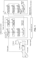
- Fig. 1 is a block diagram illustrating the configuration of the measurement system 1 according to this embodiment.
- a conveyer 8 moves a work piece 5 that is a target of which a shape is to be measured
- an encoder 6 detects a position of the work piece 5 in a horizontal direction
- a sensor (measurement device) 7 detects a position of the work piece 5 in a vertical direction.
- the measurement system 1 includes a counter unit 2, an analog input unit 3, and a PLC (data processing device) 4.
- the counter unit 2 counts pulse signals output by the encoder 6 and transmits target time information to the PLC 4.
- the analog input unit 3 transmits an output signal from the sensor 7 to the PLC 4 as a measured value together with measurement time information.
- the PLC 4 acquires target time information from the counter unit 2, acquires the measured value and the measurement time information from the analog input unit 3, and then inspects the shape of the work piece 5.
- the PLC 4 determines the appropriateness/inappropriateness of the shape of the work piece 5 by comparing the shape of the measured work piece 5 with master data.
- the counter unit 2 includes a measurement unit 21, a comparison unit 22, a time information processing unit 23, an output unit 24, a target value storage unit 25, and a target value setting unit 26.
- the measurement unit 21 measures an actually-measured value by counting the number of pulses of a pulse signal output from the encoder 6.
- the comparison unit 22 determines coincidence between an actually-measured value measured by the measurement unit 21 and a target value.
- the time information processing unit 23 stores a time corresponding to the actually-measured value in a buffer as target time information.
- the output unit 24 outputs multiple pieces of target time information stored in the buffer to the PLC (an external device) 4 through communication with a predetermined communication period.
- the target value storage unit 25 stores a list of target values.
- the comparison unit 22 may determine coincidence between the actually-measured value and the target value by referring to the target value storage unit 25.
- the comparison unit 22 may determine coincidence between the actually-measured value and a target value set at predetermined intervals.
- the target value setting unit 26 accepts a target value setting instruction from a user.
- the target value setting instruction for example, may be configured to be accepted from a setting value input device such as a notebook PC through a universal serial bus (USB) or may be configured to be accepted from a PLC 4 to which a setting value input device is connected via a communication network.
- a setting value input device such as a notebook PC through a universal serial bus (USB)
- USB universal serial bus
- a method of designating a target value is not particularly limited. For example, multiple target positions may be aligned in a table (for example, 0, 5, 10, 20, ... etc.). In addition, a start position, an end position, and the number of divisions may be designated (with a pitch of 10 from 0 to 1000). Furthermore, only the amount of change may be designated (+10 or the like).
- the PLC 4 is an industrial controller and controls a device that is a control target.
- a control unit of the PLC 4 may be connected to the counter unit 2 and the analog input unit 3 through a bus or may be connected thereto using EtherCAT (a registered trademark), EtherNet/IP (a registered trademark), DeviceNet (a registered trademark), CompoNet (a registered trademark), or the like through a communication coupler.
- the PLC (a data processing device) 4 includes a time information receiving unit 41, a measured value acquiring unit 42, a measured value identifying unit 43, and a determination unit 44.
- the time information receiving unit 41 receives target time information from the counter unit 2.
- the measured value acquiring unit 42 acquires a measured value and measurement time information acquired by the sensor (a predetermined measurement device) 7.
- the measured value identifying unit 43 identifies a measured value having measurement time information within a predetermined range for a time indicated by the target time information.
- the determination unit 44 determines whether or not a difference between master data representing a correct answer value of the measured value and the measured value identified by the measured value identifying unit 43 is within an allowed range.
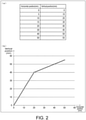
- Fig. 2 is a diagram illustrating an example of master data representing the shape of a work piece 5 according to this embodiment.
- (a) of Fig. 2 is an example in which master data is represented in a table form.
- (b) of Fig. 2 is an example in which master data is represented in a graph form.
- the master data is composed of numerical data representing a horizontal position (mm) and a vertical position (mm) that are associated with each other.
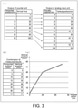
- Fig. 3 is a diagram illustrating an example of results of measurement (hereinafter, referred to as "measurement results") of the shape of the work piece 5 according to this embodiment.
- (a) of Fig. 3 is an example in which two measurement results are represented in a table form.
- (b) of Fig. 3 is an example in which a combination of measurement results is represented in a graph form.
- (c) of Fig. 3 is an example in which a combination of measurement results is represented in a graph form.
- the counter unit 2 identifies a time of arrival at a horizontal position designated by a user (hereinafter, referred to as an "arrival time") and outputs the identified time to the PLC 4.
- the analog input unit 3 outputs a vertical position (one of equally-spaced times and a vertical position) at each predetermined time interval to the PLC 4.
- the PLC 4 searches equally-spaced times acquired from the analog input unit 3 using the arrival time acquired from the counter unit 2 as a key and acquires combination data that is a combination of a horizontal position and a vertical position at times that are close to each other.
- an arrival time output by the counter unit 2 and one of equally-spaced times that is a time for each predetermined time interval in the analog input unit 3 are associated with each other.
- (b) and (c) of Fig. 3 illustrate combination data acquired by combining a horizontal position corresponding to an arrival time and a vertical position corresponding to one of equally-spaced times in a case in which the arrival time and the equally-spaced time are associated with each other.
- the PLC 4 compares the combination data with master data.
- the measurement unit 21 counts the number of pulses of a pulse signal output by the encoder 6 and measures a counting value (an actually-measured value) (measuring step). Then, the counter unit 2 performs the following processes at the timings stated above.
- the comparison unit 22 reads a counting value from the measurement unit 21. Then, the comparison unit 22 reads a target value from the target value storage unit 25 in accordance with a pointer.
- the pointer indicates a target value to be compared with the counting value next among multiple target values or a storage position of the target value.
- the comparison unit 22 determines whether or not the counting value read in Step S401 is equal to or larger than a target value. In a case in which the counting value is equal to or larger than the target value (Yes in Step S402), the counter unit 2 performs processes of Steps S403 and S404. In a case in which the counting value is not equal to or larger than the target value (is smaller than the target value) (No in Step S402), the counter unit 2 skips the processes of Steps S403 and S404 and performs determination of Step S405.
- Step S403 Time information processing step
- the time information processing unit 23 stores a time corresponding to the counting value that is equal to or larger than the target value in a coincidence time buffer as target time information.
- a coincidence time buffer times (target time information) corresponding to counting values that are equal to or larger than each target value are sequentially stored.
- the counter unit 2 updates a pointer (for example, an address on a memory or the like) in a case in which a target value is read.
- a pointer for example, an address on a memory or the like
- the counter unit 2 determines whether or not a communication period has been reached.
- the communication period is a period corresponding to the control period of the PLC 4 and represents a time interval for transmitting data from the counter unit 2 to the PLC 4.
- the counter unit 2 performs processes of Steps S406 and S407.
- the counter unit 2 skips the processes of Step S406 and S407 and ends the process.
- Step S406 Output step
- the output unit 24 generates transmission data from multiple pieces of target time information stored in the coincidence time buffer and outputs the transmission data to the PLC 4 through communication.
- the counter unit 2 initializes the coincidence time buffer.
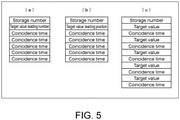
- Fig. 5 is a diagram illustrating an example of the configuration of transmission data from the counter unit 2 to the PLC 4 according to this embodiment.
- methods for representing a target value for transmission data there are multiple options.
- the transmission data includes a storage number, a target value leading number, and multiple coincidence times.
- the storage number represents the number of coincidence times stored in the coincidence buffer (hereinafter, the same).
- the target value leading number represents a number of a target value corresponding to a leading coincidence time among target values stored in the table. In the description presented above, only the target value leading number is added to the target value, and thus the amount of transmission data can be reduced.
- transmission data includes a storage number, a target value leading position, and multiple coincidence times.
- the target value leading position represents a position (horizontal position) of a target value corresponding to a leading coincidence time among target values stored in the table. According to the description presented above, only the target value leading position is added to the target values, and thus the transmission data can be reduced.
- transmission data includes a storage number and multiple combinations each including a target value and a coincidence time.
- Fig. 6 is a flowchart illustrating an example of the process of the PLC 4 according to this embodiment. The process is performed for every communication period.
- Step S601 Time information receiving step, measured value acquiring step
- the time information receiving unit 41 receives transmission data (target time information) from the counter unit 2.
- the measured value acquiring unit 42 acquires a measured value acquired using the sensor 7 and measurement time information from the analog input unit 3.
- the PLC 4 determines whether or not target value coincidence times (hereinafter, referred to as coincidence times), which have not been processed, are stored in the transmission data. In a case in which coincidence times, which have not been processed, are stored (Yes in Step S602), the PLC 4 performs processes of Step S603 and subsequent steps. In a case in which no coincidence time, which has not been processed is stored (No in Step S602), the PLC 4 skips processes of Step S603 and subsequent steps and ends the process.
- coincidence times target value coincidence times
- the PLC 4 takes out one combination of a first coincidence time and a horizontal position among coincidence times that have not been processed from the transmission data received from the counter unit 2.
- Step S604 Measured value identifying step
- the PLC 4 takes out a vertical position of a time close to the coincidence time of Step S603 from the data received from the analog input unit 3.
- the measured value identifying unit 43 identifies a measured value having measurement time information within a predetermined range with respect to a time represented in the target time information.
- the PLC 4 takes out a vertical position corresponding to a horizontal position coinciding with the target value from the master data.
- the PLC 4 determines whether or not the vertical position of the analog input unit 3 is within an allowed range of the vertical position of the master data. In a case in which the vertical position is within the allowed range (Yes in Step S606), the PLC 4 performs determination of Step S607. In a case in which the vertical position is not within the allowed range (No in Step S606), the PLC 4 performs a process of Step S609.
- the PLC 4 determines whether or not the horizontal position reaches a final position. In a case in which the horizontal position has reached the final position (Yes in Step S607), the PLC 4 performs a process of Step S608. In a case in which the horizontal position has not reached the final position (No in Step S607), the PLC 4 performs the determination of Step S602 again.
- the PLC 4 sets an inspection result to OK. This represents that all the vertical positions that have been measured are within the allowed range of the master data. Then, the PLC 4 ends the process.
- the PLC 4 sets the inspection result to NG. This represents that at least one of vertical positions that have been measured is not within the allowed range of the master data. Then, the PLC 4 ends the process.
- Each of the functional blocks of the counter unit 2 and the PLC 4 may be realized by a logical circuit (hardware) formed in an integrated circuit (IC chip) or the like or may be realized by software.
- each of the counter unit 2 and the PLC 4 includes a computer that executes commands of a program that is software realizing each function.
- This computer for example, includes one or more processors and includes a computer-readable recording medium storing the program described above. Then, in the computer described above, the processors described above read the program described above from the recording medium and execute the read program, whereby the objective of the present invention is achieved.
- a central processing unit CPU
- CPU central processing unit
- a medium of a non-transitory type for example, in addition to a read only memory (ROM) or the like, a tape, a disk, a card, a semiconductor memory, a programmable logic circuit, or the like may be used.
- a random access memory (RAM) or the like expanding the program described above may be further included.
- the program described above may be supplied to the computer described above through an arbitrary transmission medium (a communication network, a broadcast wave, or the like) that can transmit the program.
- one aspect of the present invention may be realized in the form of data signal embedded in a carrier wave in which the program described above is implemented through electronic transmission.
- a counter unit including: a measurement unit configured to measure an actually-measured value by counting a number of pulses of a pulse signal; a comparison unit configured to determine coincidence between the actually-measured value measured by the measurement unit and a target value; a time information processing unit configured to store a time corresponding to the actually-measured value in a buffer as target time information when the comparison unit determines that the actually-measured value and the target value coincide with each other; and an output unit configured to output a plurality of pieces of target time information stored in the buffer to an external device through communication with a predetermined communication period.
- position information based on an output from the counter unit and a measured value that is measured by another measurement device can be associated with each other using target time information corresponding to a target value.
- target value for example, for an external device, position information based on an output from the counter unit and a measured value that is measured by another measurement device can be associated with each other using target time information corresponding to a target value.
- the counter unit outputs target time information corresponding to a target value, and thus occurrence of unevenness of measurement accuracy according to unevenness of the movement speed of a measurement target, which occurs conventionally in a case in which counter output is performed with a predetermined period, can be prevented.
- the counter unit may further include a target value storage unit configured to store a list of the target values, and the comparison unit may determine coincidence between the actually-measured value and the target value by referring to the target value storage unit.
- each target value can be appropriately set in accordance with necessary accuracy thereof. For example, in a case in which there are a position requiring high accuracy, a position that may have low accuracy, and the like, each target value can be set in accordance therewith.
- the comparison unit may determine coincidence with the actually-measured value using the target values set at predetermined intervals.
- an output interval of the target time information with necessary accuracy can be set.
- the counter unit may further include a target value setting unit configured to accept a setting instruction for setting the target value.
- the setting of a target value can be appropriately changed in accordance with a measurement target.
- a data processing device including: a time information receiving unit configured to receive the target time information from the counter unit described above; a measured value acquiring unit configured to acquire a measured value and measurement time information from a predetermined measurement device; and a measured value identifying unit configured to identify a measured value having the measurement time information that is within a predetermined range for a time represented by the target time information.
- a measured value corresponding to the target time information received from the counter unit can be identified, and thus measured values can be limited to a measurement value group of accuracy that is necessary and sufficient. Therefore, processes for measured values after that, the load of communication, and the like can be reduced.
- the data processing device may further include a determination unit configured to determine whether or not a difference between master data representing a correct answer value of the measured value that corresponds to the target value and the measured value identified by the measured value identifying unit is within an allowed range.
- the data processing device can be appropriately used for an inspection of the shape of a product and the like.
- a measurement system including: the counter unit described above; the data processing device; and an analog input unit configured to transmit an output signal from a predetermined sensor as the measured value to the data processing device together with the measurement time information.
- a counter unit control method including: a measuring step of measuring an actually-measured value by counting a number of pulses of a pulse signal; a comparing step of determining coincidence between the actually-measured value measured by the measuring step and a target value; a time information processing step of storing a time corresponding to the actually-measured value in a buffer as target time information when it is determined by the comparing step that the actually-measured value and the target value coincide with each other; and an output step of outputting a plurality of pieces of target time information stored in the buffer to an external device through communication with a predetermined communication period.
- a data processing method including: a time information receiving step of receiving the target time information from the counter unit described above; a measured value acquiring step of acquiring a measured value and measurement time information from a predetermined measurement device; and a measured value identifying step of identifying a measured value having the measurement time information that is within a predetermined range for a time represented by the target time information.
Landscapes
- Physics & Mathematics (AREA)
- General Physics & Mathematics (AREA)
- Engineering & Computer Science (AREA)
- Computer Networks & Wireless Communication (AREA)
- Arrangements For Transmission Of Measured Signals (AREA)
- Recording Measured Values (AREA)
Abstract
Description
- The present invention relates to a counter unit that counts pulse signals and the like.
- As a conventional technology, a high-speed counter unit that counts pulse signals output from an encoder or the like and transmits a result of the counting to a programmable logic controller (PLC) is known. Such a high-speed counter unit can count pulses in a period shorter than a control period.
-
- [Patent Literature 1]
Japanese Patent Application Laid-Open No. 2018-024044 - [Patent Literature 2]
Japanese Patent Application Laid-Open No. H7-040522 - However, transmission of a counter current value to a PLC is performed for every control period, and the resolution may be insufficient for uses such as shape measurement and the like.
- Recently, in order to secure resolution, products in which an over-sampling function is installed have appeared. In such an over-sampling function, after current counter values have accumulated in a buffer in a period shorter than a control period, later, the counter values can then be transmitted from the buffer to a PLC altogether. In this case, the counter current positions are acquired at predetermined time intervals. For this reason, there is a characteristic that the granularity of the amount of change of the counter current position changes in accordance with the speed of pulses. Here, the time interval can be set by a user.
- In uses for shape measurement and the like, the amount of change of the current position becomes the granularity of an inspection, and thus a sampling period is determined in accordance with the necessary accuracy. However, in a case in which the sampling period is randomly shortened, the amount of data increases, and there is a problem in that a communication load and a data processing load increase.
- In addition, there is a demand for desiring to change the accuracy in accordance with the portion of an inspection target, and there may be nonuniformity in the movement speed of the inspection target, and thus there is a problem in that it may be difficult to determine an optimal sampling period. For example, when the sampling period is determined in accordance with a part for which granularity is necessary, redundant data is acquired from a part for which such granularity is not necessary.
- In
Patent Literature 1, a technology for enabling a counter to transmit a plurality of measured amounts of movement and a measurement timing of each amount of movement has been disclosed. In addition, inPatent Literature 2, a technology for counting output pulses of an encoder and outputting a signal at a time point at which a target value is matched has been disclosed. However, none of this patent literature solves the problems described above. - An objective of one aspect of the present invention is to reduce a communication load and a data processing load in a case in which pulse signals are counted and maintain measurement accuracy even when the movement speed of a measurement target changes.
- In order to solve the problems described above, according to one aspect of the present invention, there is provided a counter unit including: a measurement unit configured to measure an actually-measured value by counting a number of pulses of a pulse signal; a comparison unit configured to determine coincidence between the actually-measured value measured by the measurement unit and a target value; a time information processing unit configured to store a time corresponding to the actually-measured value in a buffer as target time information when the comparison unit determines that the actually-measured value and the target value coincide with each other; and an output unit configured to output a plurality of pieces of target time information stored in the buffer to an external device through communication with a predetermined communication period.
- According to one aspect of the present invention, there is provided a counter unit control method including: a measuring step of measuring an actually-measured value by counting a number of pulses of a pulse signal; a comparing step of determining coincidence between the actually-measured value measured by the measuring step and a target value; a time information processing step of storing a time corresponding to the actually-measured value in a buffer as target time information when it is determined by the comparing step that the actually-measured value and the target value coincide with each other; and an output step of outputting a plurality of pieces of target time information stored in the buffer to an external device through communication with a predetermined communication period.
- According to one aspect of the present invention, there is provided a data processing method including: a time information receiving step of receiving the target time information from the counter unit described above; a measured value acquiring step of acquiring a measured value and measurement time information from a predetermined measurement device; and a measured value identifying step of identifying a measured value having the measurement time information that is within a predetermined range for a time represented by the target time information.
- According to one aspect of the present invention, a communication load and a data processing load can be reduced in a case in which pulse signals are counted, and measurement accuracy can be maintained even when the movement speed of a measurement target changes.
-
-
Fig. 1 is a block diagram illustrating the configuration of a measurement system according toEmbodiment 1 of the present invention. -
Fig. 2 is a diagram illustrating an example of master data representing the shape of a work piece according toEmbodiment 1 of the present invention. -
Fig. 3 is a diagram illustrating an example of a result of measurement of the shape of a work piece according toEmbodiment 1 of the present invention. -
Fig. 4 is a flowchart illustrating an example of the process of a counter unit according toEmbodiment 1 of the present invention. -
Fig. 5 is a diagram illustrating an example of the configuration of transmission data from a counter unit to a PLC according toEmbodiment 1 of the present invention. -
Fig. 6 is a flowchart illustrating an example of the process of a PLC according toEmbodiment 1 of the present invention. - Hereinafter, an embodiment according to one aspect of the present invention (hereinafter, also referred to as "this embodiment") will be described with reference to
Figs. 1 to 6 . In the drawings, the same reference signs are assigned to the same parts or parts corresponding to each other, and description thereof will not be repeated. In this embodiment, for example, acounter unit 2 will be described as a typical example of a counter unit. In order to allow easy understanding of thecounter unit 2 according to one aspect of the present invention, first, an overview of ameasurement system 1 including thecounter unit 2 will be described with reference toFig. 1 . -
Fig. 1 is a block diagram illustrating the configuration of themeasurement system 1 according to this embodiment. As illustrated inFig. 1 , in themeasurement system 1, while aconveyer 8 moves awork piece 5 that is a target of which a shape is to be measured, anencoder 6 detects a position of thework piece 5 in a horizontal direction, and a sensor (measurement device) 7 detects a position of thework piece 5 in a vertical direction. - The
measurement system 1 includes acounter unit 2, an analog input unit 3, and a PLC (data processing device) 4. Thecounter unit 2 counts pulse signals output by theencoder 6 and transmits target time information to thePLC 4. The analog input unit 3 transmits an output signal from thesensor 7 to thePLC 4 as a measured value together with measurement time information. ThePLC 4 acquires target time information from thecounter unit 2, acquires the measured value and the measurement time information from the analog input unit 3, and then inspects the shape of thework piece 5. In more detail, thePLC 4 determines the appropriateness/inappropriateness of the shape of thework piece 5 by comparing the shape of the measuredwork piece 5 with master data. - As illustrated in
Fig. 1 , thecounter unit 2 includes ameasurement unit 21, acomparison unit 22, a timeinformation processing unit 23, anoutput unit 24, a targetvalue storage unit 25, and a targetvalue setting unit 26. Themeasurement unit 21 measures an actually-measured value by counting the number of pulses of a pulse signal output from theencoder 6. Thecomparison unit 22 determines coincidence between an actually-measured value measured by themeasurement unit 21 and a target value. In a case in which thecomparison unit 22 determines that the actually-measured value and the target value coincide with each other, the timeinformation processing unit 23 stores a time corresponding to the actually-measured value in a buffer as target time information. Theoutput unit 24 outputs multiple pieces of target time information stored in the buffer to the PLC (an external device) 4 through communication with a predetermined communication period. - The target
value storage unit 25 stores a list of target values. In accordance with this, thecomparison unit 22 may determine coincidence between the actually-measured value and the target value by referring to the targetvalue storage unit 25. Here, thecomparison unit 22 may determine coincidence between the actually-measured value and a target value set at predetermined intervals. - The target
value setting unit 26 accepts a target value setting instruction from a user. The target value setting instruction, for example, may be configured to be accepted from a setting value input device such as a notebook PC through a universal serial bus (USB) or may be configured to be accepted from aPLC 4 to which a setting value input device is connected via a communication network. - A method of designating a target value is not particularly limited. For example, multiple target positions may be aligned in a table (for example, 0, 5, 10, 20, ... etc.). In addition, a start position, an end position, and the number of divisions may be designated (with a pitch of 10 from 0 to 1000). Furthermore, only the amount of change may be designated (+10 or the like).
- The
PLC 4 is an industrial controller and controls a device that is a control target. A control unit of thePLC 4 may be connected to thecounter unit 2 and the analog input unit 3 through a bus or may be connected thereto using EtherCAT (a registered trademark), EtherNet/IP (a registered trademark), DeviceNet (a registered trademark), CompoNet (a registered trademark), or the like through a communication coupler. - As illustrated in
Fig. 1 , the PLC (a data processing device) 4 includes a timeinformation receiving unit 41, a measuredvalue acquiring unit 42, a measuredvalue identifying unit 43, and adetermination unit 44. The timeinformation receiving unit 41 receives target time information from thecounter unit 2. The measuredvalue acquiring unit 42 acquires a measured value and measurement time information acquired by the sensor (a predetermined measurement device) 7. The measuredvalue identifying unit 43 identifies a measured value having measurement time information within a predetermined range for a time indicated by the target time information. Thedetermination unit 44 determines whether or not a difference between master data representing a correct answer value of the measured value and the measured value identified by the measuredvalue identifying unit 43 is within an allowed range. -
Fig. 2 is a diagram illustrating an example of master data representing the shape of awork piece 5 according to this embodiment. (a) ofFig. 2 is an example in which master data is represented in a table form. (b) ofFig. 2 is an example in which master data is represented in a graph form. As illustrated in (a) and (b) ofFig. 2 , the master data is composed of numerical data representing a horizontal position (mm) and a vertical position (mm) that are associated with each other. -
Fig. 3 is a diagram illustrating an example of results of measurement (hereinafter, referred to as "measurement results") of the shape of thework piece 5 according to this embodiment. (a) ofFig. 3 is an example in which two measurement results are represented in a table form. (b) ofFig. 3 is an example in which a combination of measurement results is represented in a graph form. (c) ofFig. 3 is an example in which a combination of measurement results is represented in a graph form. - The
counter unit 2 identifies a time of arrival at a horizontal position designated by a user (hereinafter, referred to as an "arrival time") and outputs the identified time to thePLC 4. The analog input unit 3 outputs a vertical position (one of equally-spaced times and a vertical position) at each predetermined time interval to thePLC 4. - The
PLC 4 searches equally-spaced times acquired from the analog input unit 3 using the arrival time acquired from thecounter unit 2 as a key and acquires combination data that is a combination of a horizontal position and a vertical position at times that are close to each other. - As denoted by arrows illustrated in (a) of
Fig. 3 , an arrival time output by thecounter unit 2 and one of equally-spaced times that is a time for each predetermined time interval in the analog input unit 3 are associated with each other. (b) and (c) ofFig. 3 illustrate combination data acquired by combining a horizontal position corresponding to an arrival time and a vertical position corresponding to one of equally-spaced times in a case in which the arrival time and the equally-spaced time are associated with each other. - Then, the
PLC 4 compares the combination data with master data. - According to the description presented above, in regards to a horizontal position, points for a shape inspection can be directly designated, and thus the operation is simple, and redundant data does not need to be acquired. Further, an amount of acquired data becomes a necessary minimum, and thus a communication load and a data processing load can be reduced. Even when movement of the
work piece 5 in the horizontal direction according to theconveyer 8 is accelerated/decelerated, or there is unevenness in the movement speed, there is no influence on the inspection accuracy for the horizontal position. In addition, the vertical position is acquired for each sampling period of the analog input unit 3. -
Fig. 4 is a flowchart illustrating an example of the process of thecounter unit 2 according to this embodiment. This process may be started for each sampling period of data output from theencoder 6 or may be started in accordance with an interrupt triggered upon detection of "counting value = target value" in the comparator. In the case of the interrupt of the comparator, the process is started from Step S403 illustrated inFig. 4 . - First, in the
counter unit 2, themeasurement unit 21 counts the number of pulses of a pulse signal output by theencoder 6 and measures a counting value (an actually-measured value) (measuring step). Then, thecounter unit 2 performs the following processes at the timings stated above. - In the
counter unit 2, thecomparison unit 22 reads a counting value from themeasurement unit 21. Then, thecomparison unit 22 reads a target value from the targetvalue storage unit 25 in accordance with a pointer. The pointer indicates a target value to be compared with the counting value next among multiple target values or a storage position of the target value. - The
comparison unit 22 determines whether or not the counting value read in Step S401 is equal to or larger than a target value. In a case in which the counting value is equal to or larger than the target value (Yes in Step S402), thecounter unit 2 performs processes of Steps S403 and S404. In a case in which the counting value is not equal to or larger than the target value (is smaller than the target value) (No in Step S402), thecounter unit 2 skips the processes of Steps S403 and S404 and performs determination of Step S405. - The time
information processing unit 23 stores a time corresponding to the counting value that is equal to or larger than the target value in a coincidence time buffer as target time information. In the coincidence time buffer, times (target time information) corresponding to counting values that are equal to or larger than each target value are sequentially stored. - The
counter unit 2 updates a pointer (for example, an address on a memory or the like) in a case in which a target value is read. - The
counter unit 2 determines whether or not a communication period has been reached. The communication period is a period corresponding to the control period of thePLC 4 and represents a time interval for transmitting data from thecounter unit 2 to thePLC 4. In a case in which the communication period has been reached (Yes in Step S405), thecounter unit 2 performs processes of Steps S406 and S407. In a case in which the communication period has not been reached (No in Step S405), thecounter unit 2 skips the processes of Step S406 and S407 and ends the process. - In the
counter unit 2, theoutput unit 24 generates transmission data from multiple pieces of target time information stored in the coincidence time buffer and outputs the transmission data to thePLC 4 through communication. - The
counter unit 2 initializes the coincidence time buffer. -
Fig. 5 is a diagram illustrating an example of the configuration of transmission data from thecounter unit 2 to thePLC 4 according to this embodiment. As methods for representing a target value for transmission data, there are multiple options. - In a case in which target values are registered in a table, as illustrated in (a) of
Fig. 5 , a method in which thecounter unit 2 adds a target value leading number of the table may be selected. In more detail, the transmission data includes a storage number, a target value leading number, and multiple coincidence times. The storage number represents the number of coincidence times stored in the coincidence buffer (hereinafter, the same). The target value leading number represents a number of a target value corresponding to a leading coincidence time among target values stored in the table. In the description presented above, only the target value leading number is added to the target value, and thus the amount of transmission data can be reduced. - In a case in which target values are registered in a table, as illustrated in (b) of
Fig. 5 , a method in which thecounter unit 2 adds a target value leading position of the table may be selected. In more detail, transmission data includes a storage number, a target value leading position, and multiple coincidence times. The target value leading position represents a position (horizontal position) of a target value corresponding to a leading coincidence time among target values stored in the table. According to the description presented above, only the target value leading position is added to the target values, and thus the transmission data can be reduced. - As illustrated in (c) of
Fig. 5 , a method in which thecounter unit 2 adds all the target values may be selected. In more detail, transmission data includes a storage number and multiple combinations each including a target value and a coincidence time. -
Fig. 6 is a flowchart illustrating an example of the process of thePLC 4 according to this embodiment. The process is performed for every communication period. - In the
PLC 4, the timeinformation receiving unit 41 receives transmission data (target time information) from thecounter unit 2. In addition, the measuredvalue acquiring unit 42 acquires a measured value acquired using thesensor 7 and measurement time information from the analog input unit 3. - The
PLC 4 determines whether or not target value coincidence times (hereinafter, referred to as coincidence times), which have not been processed, are stored in the transmission data. In a case in which coincidence times, which have not been processed, are stored (Yes in Step S602), thePLC 4 performs processes of Step S603 and subsequent steps. In a case in which no coincidence time, which has not been processed is stored (No in Step S602), thePLC 4 skips processes of Step S603 and subsequent steps and ends the process. - The
PLC 4 takes out one combination of a first coincidence time and a horizontal position among coincidence times that have not been processed from the transmission data received from thecounter unit 2. - The
PLC 4 takes out a vertical position of a time close to the coincidence time of Step S603 from the data received from the analog input unit 3. In other words, the measuredvalue identifying unit 43 identifies a measured value having measurement time information within a predetermined range with respect to a time represented in the target time information. - The
PLC 4 takes out a vertical position corresponding to a horizontal position coinciding with the target value from the master data. - The
PLC 4 determines whether or not the vertical position of the analog input unit 3 is within an allowed range of the vertical position of the master data. In a case in which the vertical position is within the allowed range (Yes in Step S606), thePLC 4 performs determination of Step S607. In a case in which the vertical position is not within the allowed range (No in Step S606), thePLC 4 performs a process of Step S609. - The
PLC 4 determines whether or not the horizontal position reaches a final position. In a case in which the horizontal position has reached the final position (Yes in Step S607), thePLC 4 performs a process of Step S608. In a case in which the horizontal position has not reached the final position (No in Step S607), thePLC 4 performs the determination of Step S602 again. - The
PLC 4 sets an inspection result to OK. This represents that all the vertical positions that have been measured are within the allowed range of the master data. Then, thePLC 4 ends the process. - The
PLC 4 sets the inspection result to NG. This represents that at least one of vertical positions that have been measured is not within the allowed range of the master data. Then, thePLC 4 ends the process. - Each of the functional blocks of the
counter unit 2 and the PLC 4 (more specifically, themeasurement unit 21, thecomparison unit 22, the timeinformation processing unit 23, theoutput unit 24, the targetvalue storage unit 25, the targetvalue setting unit 26, the timeinformation receiving unit 41, the measuredvalue acquiring unit 42, the measuredvalue identifying unit 43, and the determination unit 44) may be realized by a logical circuit (hardware) formed in an integrated circuit (IC chip) or the like or may be realized by software. - In the latter case, each of the
counter unit 2 and thePLC 4 includes a computer that executes commands of a program that is software realizing each function. This computer, for example, includes one or more processors and includes a computer-readable recording medium storing the program described above. Then, in the computer described above, the processors described above read the program described above from the recording medium and execute the read program, whereby the objective of the present invention is achieved. As the processor described above, for example, a central processing unit (CPU) may be used. As the recording medium described above, "a medium of a non-transitory type", for example, in addition to a read only memory (ROM) or the like, a tape, a disk, a card, a semiconductor memory, a programmable logic circuit, or the like may be used. In addition, a random access memory (RAM) or the like expanding the program described above may be further included. In addition, the program described above may be supplied to the computer described above through an arbitrary transmission medium (a communication network, a broadcast wave, or the like) that can transmit the program. Furthermore, one aspect of the present invention may be realized in the form of data signal embedded in a carrier wave in which the program described above is implemented through electronic transmission. - According to one aspect of the present invention, there is provided a counter unit including: a measurement unit configured to measure an actually-measured value by counting a number of pulses of a pulse signal; a comparison unit configured to determine coincidence between the actually-measured value measured by the measurement unit and a target value; a time information processing unit configured to store a time corresponding to the actually-measured value in a buffer as target time information when the comparison unit determines that the actually-measured value and the target value coincide with each other; and an output unit configured to output a plurality of pieces of target time information stored in the buffer to an external device through communication with a predetermined communication period.
- According to the configuration described above, for example, for an external device, position information based on an output from the counter unit and a measured value that is measured by another measurement device can be associated with each other using target time information corresponding to a target value. Here, by setting the target value to a degree for which necessary accuracy is acquired, a position and a measured value can be associated with each other with sufficient accuracy without being influenced by the communication period.
- In addition, an output that is detailed more than necessary does not need to be performed from the counter unit, and thus the load of communication and the load of data processing in an external device can be reduced.
- Furthermore, the counter unit outputs target time information corresponding to a target value, and thus occurrence of unevenness of measurement accuracy according to unevenness of the movement speed of a measurement target, which occurs conventionally in a case in which counter output is performed with a predetermined period, can be prevented.
- The counter unit according to one aspect of the present invention may further include a target value storage unit configured to store a list of the target values, and the comparison unit may determine coincidence between the actually-measured value and the target value by referring to the target value storage unit.
- According to the configuration described above, each target value can be appropriately set in accordance with necessary accuracy thereof. For example, in a case in which there are a position requiring high accuracy, a position that may have low accuracy, and the like, each target value can be set in accordance therewith.
- In the counter unit according to one aspect of the present invention, the comparison unit may determine coincidence with the actually-measured value using the target values set at predetermined intervals.
- According to the configuration described above, by setting an interval between target values in accordance with necessary accuracy, an output interval of the target time information with necessary accuracy can be set.
- The counter unit according to one aspect of the present invention may further include a target value setting unit configured to accept a setting instruction for setting the target value.
- According to the configuration described above, the setting of a target value can be appropriately changed in accordance with a measurement target.
- According to one aspect of the present invention, there is provided a data processing device including: a time information receiving unit configured to receive the target time information from the counter unit described above; a measured value acquiring unit configured to acquire a measured value and measurement time information from a predetermined measurement device; and a measured value identifying unit configured to identify a measured value having the measurement time information that is within a predetermined range for a time represented by the target time information.
- According to the configuration described above, a measured value corresponding to the target time information received from the counter unit can be identified, and thus measured values can be limited to a measurement value group of accuracy that is necessary and sufficient. Therefore, processes for measured values after that, the load of communication, and the like can be reduced.
- The data processing device according to one aspect of the present invention may further include a determination unit configured to determine whether or not a difference between master data representing a correct answer value of the measured value that corresponds to the target value and the measured value identified by the measured value identifying unit is within an allowed range.
- According to the configuration described above, presence/absence of a difference from the master data can be determined, and therefore, for example, the data processing device can be appropriately used for an inspection of the shape of a product and the like.
- According to one aspect of the present invention, there is provided a measurement system including: the counter unit described above; the data processing device; and an analog input unit configured to transmit an output signal from a predetermined sensor as the measured value to the data processing device together with the measurement time information.
- According to one aspect of the present invention, there is provided a counter unit control method including: a measuring step of measuring an actually-measured value by counting a number of pulses of a pulse signal; a comparing step of determining coincidence between the actually-measured value measured by the measuring step and a target value; a time information processing step of storing a time corresponding to the actually-measured value in a buffer as target time information when it is determined by the comparing step that the actually-measured value and the target value coincide with each other; and an output step of outputting a plurality of pieces of target time information stored in the buffer to an external device through communication with a predetermined communication period.
- According to one aspect of the present invention, there is provided a data processing method including: a time information receiving step of receiving the target time information from the counter unit described above; a measured value acquiring step of acquiring a measured value and measurement time information from a predetermined measurement device; and a measured value identifying step of identifying a measured value having the measurement time information that is within a predetermined range for a time represented by the target time information.
- The present invention is not limited to each of the embodiments described above, various modifications can be made in a range represented by the claims, and an embodiment acquired by appropriately combining technical means disclosed in different embodiments also belongs to the technical scope of the present invention.
-
- 1
- Measurement system
- 2
- Counter unit
- 3
- Analog input unit
- 4
- PLC (external device, data processing device)
- 7
- Sensor (measurement device)
- 21
- Measurement unit
- 22
- Comparison unit
- 23
- Time information processing unit
- 24
- Output unit
- 25
- Target value storage unit
- 26
- Target value setting unit
- 41
- Time information receiving unit
- 42
- Measured value acquiring unit
- 43
- Measured value identifying unit
- 44
- Determination unit
Claims (9)
- A counter unit comprising:a measurement unit configured to measure an actually-measured value by counting a number of pulses of a pulse signal;a comparison unit configured to determine coincidence between the actually-measured value measured by the measurement unit and a target value;a time information processing unit configured to store a time corresponding to the actually-measured value in a buffer as target time information when the comparison unit determines that the actually-measured value and the target value coincide with each other; andan output unit configured to output a plurality of pieces of target time information stored in the buffer to an external device through communication with a predetermined communication period.
- The counter unit according to claim 1, further comprising a target value storage unit configured to store a list of the target values,
wherein the comparison unit determines coincidence between the actually-measured value and the target value by referring to the target value storage unit. - The counter unit according to claim 1, wherein the comparison unit determines coincidence with the actually-measured value using the target values set at a predetermined interval.
- The counter unit according to any one of claims 1 to 3, further comprising a target value setting unit configured to accept a setting instruction for setting the target value.
- A data processing device comprising:a time information receiving unit configured to receive the target time information from the counter unit according to any one of claims 1 to 4;a measured value acquiring unit configured to acquire a measured value and measurement time information from a predetermined measurement device; anda measured value identifying unit configured to identify a measured value having the measurement time information that is within a predetermined range for a time represented by the target time information.
- The data processing device according to claim 5, further comprising a determination unit configured to determine whether or not a difference between master data representing a correct answer value of the measured value that corresponds to the target value and the measured value identified by the measured value identifying unit is within an allowed range.
- A measurement system comprising:the counter unit according to any one of claims 1 to 4;the data processing device according to claim 5 or 6; andan analog input unit configured to transmit an output signal from a predetermined sensor as the measured value to the data processing device together with the measurement time information.
- A counter unit control method comprising:a measuring step of measuring an actually-measured value by counting a number of pulses of a pulse signal;a comparing step of determining coincidence between the actually-measured value measured by the measuring step and a target value;a time information processing step of storing a time corresponding to the actually-measured value in a buffer as target time information when it is determined by the comparing step that the actually-measured value and the target value coincide with each other; andan output step of outputting a plurality of pieces of target time information stored in the buffer to an external device through communication with a predetermined communication period.
- A data processing method comprising:a time information receiving step of receiving the target time information from the counter unit according to any one of claims 1 to 4;a measured value acquiring step of acquiring a measured value and measurement time information from a predetermined measurement device; anda measured value identifying step of identifying a measured value having the measurement time information that is within a predetermined range for a time represented by the target time information.
Applications Claiming Priority (2)
| Application Number | Priority Date | Filing Date | Title |
|---|---|---|---|
| JP2019090133A JP7275827B2 (en) | 2019-05-10 | 2019-05-10 | Counter unit, data processor, measurement system, counter unit control method, and data processing method |
| PCT/JP2020/010265 WO2020230429A1 (en) | 2019-05-10 | 2020-03-10 | Counter unit, data processing device, measurement system, counter unit control method, and data processing method |
Publications (3)
| Publication Number | Publication Date |
|---|---|
| EP3967984A1 true EP3967984A1 (en) | 2022-03-16 |
| EP3967984A4 EP3967984A4 (en) | 2023-02-08 |
| EP3967984B1 EP3967984B1 (en) | 2023-12-13 |
Family
ID=73221727
Family Applications (1)
| Application Number | Title | Priority Date | Filing Date |
|---|---|---|---|
| EP20806070.7A Active EP3967984B1 (en) | 2019-05-10 | 2020-03-10 | Counter unit, data processing device, measurement system, counter unit control method, and data processing method |
Country Status (5)
| Country | Link |
|---|---|
| US (1) | US11988529B2 (en) |
| EP (1) | EP3967984B1 (en) |
| JP (1) | JP7275827B2 (en) |
| CN (1) | CN113748319B (en) |
| WO (1) | WO2020230429A1 (en) |
Families Citing this family (1)
| Publication number | Priority date | Publication date | Assignee | Title |
|---|---|---|---|---|
| CN115081578B (en) * | 2022-06-08 | 2023-11-03 | 华能核能技术研究院有限公司 | Fuel ball counter signal processing system, method and device and electronic equipment |
Family Cites Families (15)
| Publication number | Priority date | Publication date | Assignee | Title |
|---|---|---|---|---|
| US4933769A (en) | 1987-12-07 | 1990-06-12 | U.S. Philips Corporation | Picture display device including a staircase generator |
| JP3074484B2 (en) | 1990-04-10 | 2000-08-07 | 甲賀電子株式会社 | Pulse generating method and apparatus |
| JP3448908B2 (en) | 1993-07-30 | 2003-09-22 | ソニー株式会社 | Plate making equipment |
| US6118387A (en) * | 1998-07-24 | 2000-09-12 | Smc Kabushiki Kaisha | Counter |
| JP3312648B2 (en) * | 1998-09-17 | 2002-08-12 | 日本電気株式会社 | Pulse signal generating device and pulse signal generating method |
| JP2001194197A (en) | 2000-01-07 | 2001-07-19 | Fuji Electric Co Ltd | Ultrasonic flow meter |
| CN101334672B (en) | 2007-06-28 | 2010-04-21 | 上海宝信软件股份有限公司 | Online width adjusting system for crystallizer |
| WO2014103931A1 (en) | 2012-12-26 | 2014-07-03 | 株式会社Schaft | Velocity measuring device and velocity measuring method |
| US20150078405A1 (en) * | 2013-09-18 | 2015-03-19 | Alcatel Lucent Canada Inc. | Monitoring clock accuracy in asynchronous traffic environments |
| JP6689974B2 (en) * | 2016-07-06 | 2020-04-28 | 株式会社Fuji | Imaging device and imaging system |
| JP6834232B2 (en) * | 2016-08-09 | 2021-02-24 | オムロン株式会社 | Information processing system, information processing device, work position identification method, and work position identification program |
| JP2018024044A (en) | 2016-08-09 | 2018-02-15 | オムロン株式会社 | Information processing system, information processing apparatus, work position specifying method, and work position specifying program |
| JP6757287B2 (en) * | 2017-04-11 | 2020-09-16 | 東洋電機製造株式会社 | Speed detector |
| JP6919596B2 (en) * | 2018-03-01 | 2021-08-18 | オムロン株式会社 | Measurement system and method |
| JP7145695B2 (en) * | 2018-08-25 | 2022-10-03 | 株式会社チノー | Measurement result chart recording device, measurement result chart recording method, measurement result chart recording program, recording medium |
-
2019
- 2019-05-10 JP JP2019090133A patent/JP7275827B2/en active Active
-
2020
- 2020-03-10 WO PCT/JP2020/010265 patent/WO2020230429A1/en not_active Ceased
- 2020-03-10 CN CN202080028754.1A patent/CN113748319B/en active Active
- 2020-03-10 US US17/605,237 patent/US11988529B2/en active Active
- 2020-03-10 EP EP20806070.7A patent/EP3967984B1/en active Active
Also Published As
| Publication number | Publication date |
|---|---|
| US20220196440A1 (en) | 2022-06-23 |
| WO2020230429A1 (en) | 2020-11-19 |
| JP2020187435A (en) | 2020-11-19 |
| US11988529B2 (en) | 2024-05-21 |
| JP7275827B2 (en) | 2023-05-18 |
| EP3967984A4 (en) | 2023-02-08 |
| CN113748319B (en) | 2024-08-06 |
| CN113748319A (en) | 2021-12-03 |
| EP3967984B1 (en) | 2023-12-13 |
Similar Documents
| Publication | Publication Date | Title |
|---|---|---|
| EP3382481B1 (en) | Controller, control program, and control system field | |
| US4924468A (en) | Logic analyzer | |
| US20090089623A1 (en) | Event timing analyzer for a system of instruments and method of analyzing event timing in a system of intruments | |
| JP4276435B2 (en) | Synchronous clocked communication system with distributed input / output functional units and method for integrating distributed input / output functional units in such a system | |
| EP3432463A1 (en) | Motor control system, motor control device, program and recording medium | |
| JP2001352350A (en) | Measurement system and method by statistic eye-diagram of continuous bit stream | |
| JP2008209424A (en) | Jitter analyzer for lsi to be measured | |
| CN110991761B (en) | Heat supply load prediction method and device | |
| EP3967984B1 (en) | Counter unit, data processing device, measurement system, counter unit control method, and data processing method | |
| US5412311A (en) | System for unambiguously determining the phase of an input signal of relative to a clock reference signal | |
| US6894984B2 (en) | Method and device for serial data transmission between a position measuring system and a processing unit | |
| CN114331205A (en) | Product detection method and device, computer equipment and readable storage medium | |
| EP3968302A1 (en) | Signal measurement unit | |
| JP3900470B2 (en) | Digital signal measuring apparatus and traffic observation method | |
| US3696415A (en) | Adaptive pulse quantizer system | |
| EP3926428A1 (en) | Control device, control program, and control system | |
| US8775852B2 (en) | Method for sensing input signal changes | |
| EP3979504B1 (en) | Data transfer device, control device, setting device, and control method for data transfer device | |
| EP3521956B1 (en) | Input unit for acquiring sensor signals from a plurality of sensors | |
| US4646091A (en) | Airborne set for a two-way distance-ranging system | |
| SU1464172A1 (en) | Device for identifying stationarity of random process | |
| CN118777856A (en) | A processing method and device for detecting time accuracy of intelligent switch | |
| US20060047463A1 (en) | Bit synchronization for high-speed serial device testing | |
| SU1397949A1 (en) | Device for reading graphic information | |
| CN115793595A (en) | Signal processing module response time testing method and device |
Legal Events
| Date | Code | Title | Description |
|---|---|---|---|
| STAA | Information on the status of an ep patent application or granted ep patent |
Free format text: STATUS: THE INTERNATIONAL PUBLICATION HAS BEEN MADE |
|
| PUAI | Public reference made under article 153(3) epc to a published international application that has entered the european phase |
Free format text: ORIGINAL CODE: 0009012 |
|
| STAA | Information on the status of an ep patent application or granted ep patent |
Free format text: STATUS: REQUEST FOR EXAMINATION WAS MADE |
|
| 17P | Request for examination filed |
Effective date: 20211008 |
|
| AK | Designated contracting states |
Kind code of ref document: A1 Designated state(s): AL AT BE BG CH CY CZ DE DK EE ES FI FR GB GR HR HU IE IS IT LI LT LU LV MC MK MT NL NO PL PT RO RS SE SI SK SM TR |
|
| DAV | Request for validation of the european patent (deleted) | ||
| DAX | Request for extension of the european patent (deleted) | ||
| REG | Reference to a national code |
Ref legal event code: R079 Ipc: G08C0019160000 Ref country code: DE Ref legal event code: R079 Ref document number: 602020022814 Country of ref document: DE Free format text: PREVIOUS MAIN CLASS: G01D0021020000 Ipc: G08C0019160000 |
|
| A4 | Supplementary search report drawn up and despatched |
Effective date: 20230109 |
|
| RIC1 | Information provided on ipc code assigned before grant |
Ipc: G01D 5/244 19680901ALI20230102BHEP Ipc: G01D 21/02 19680901ALI20230102BHEP Ipc: H04Q 9/00 19680901ALI20230102BHEP Ipc: G08C 19/16 19680901AFI20230102BHEP |
|
| GRAP | Despatch of communication of intention to grant a patent |
Free format text: ORIGINAL CODE: EPIDOSNIGR1 |
|
| STAA | Information on the status of an ep patent application or granted ep patent |
Free format text: STATUS: GRANT OF PATENT IS INTENDED |
|
| INTG | Intention to grant announced |
Effective date: 20230727 |
|
| GRAS | Grant fee paid |
Free format text: ORIGINAL CODE: EPIDOSNIGR3 |
|
| GRAA | (expected) grant |
Free format text: ORIGINAL CODE: 0009210 |
|
| STAA | Information on the status of an ep patent application or granted ep patent |
Free format text: STATUS: THE PATENT HAS BEEN GRANTED |
|
| AK | Designated contracting states |
Kind code of ref document: B1 Designated state(s): AL AT BE BG CH CY CZ DE DK EE ES FI FR GB GR HR HU IE IS IT LI LT LU LV MC MK MT NL NO PL PT RO RS SE SI SK SM TR |
|
| REG | Reference to a national code |
Ref country code: GB Ref legal event code: FG4D |
|
| REG | Reference to a national code |
Ref country code: CH Ref legal event code: EP |
|
| REG | Reference to a national code |
Ref country code: DE Ref legal event code: R096 Ref document number: 602020022814 Country of ref document: DE |
|
| REG | Reference to a national code |
Ref country code: IE Ref legal event code: FG4D |
|
| PG25 | Lapsed in a contracting state [announced via postgrant information from national office to epo] |
Ref country code: GR Free format text: LAPSE BECAUSE OF FAILURE TO SUBMIT A TRANSLATION OF THE DESCRIPTION OR TO PAY THE FEE WITHIN THE PRESCRIBED TIME-LIMIT Effective date: 20240314 |
|
| REG | Reference to a national code |
Ref country code: LT Ref legal event code: MG9D |
|
| PG25 | Lapsed in a contracting state [announced via postgrant information from national office to epo] |
Ref country code: LT Free format text: LAPSE BECAUSE OF FAILURE TO SUBMIT A TRANSLATION OF THE DESCRIPTION OR TO PAY THE FEE WITHIN THE PRESCRIBED TIME-LIMIT Effective date: 20231213 |
|
| REG | Reference to a national code |
Ref country code: NL Ref legal event code: MP Effective date: 20231213 |
|
| PG25 | Lapsed in a contracting state [announced via postgrant information from national office to epo] |
Ref country code: ES Free format text: LAPSE BECAUSE OF FAILURE TO SUBMIT A TRANSLATION OF THE DESCRIPTION OR TO PAY THE FEE WITHIN THE PRESCRIBED TIME-LIMIT Effective date: 20231213 |
|
| PG25 | Lapsed in a contracting state [announced via postgrant information from national office to epo] |
Ref country code: LT Free format text: LAPSE BECAUSE OF FAILURE TO SUBMIT A TRANSLATION OF THE DESCRIPTION OR TO PAY THE FEE WITHIN THE PRESCRIBED TIME-LIMIT Effective date: 20231213 Ref country code: GR Free format text: LAPSE BECAUSE OF FAILURE TO SUBMIT A TRANSLATION OF THE DESCRIPTION OR TO PAY THE FEE WITHIN THE PRESCRIBED TIME-LIMIT Effective date: 20240314 Ref country code: ES Free format text: LAPSE BECAUSE OF FAILURE TO SUBMIT A TRANSLATION OF THE DESCRIPTION OR TO PAY THE FEE WITHIN THE PRESCRIBED TIME-LIMIT Effective date: 20231213 Ref country code: BG Free format text: LAPSE BECAUSE OF FAILURE TO SUBMIT A TRANSLATION OF THE DESCRIPTION OR TO PAY THE FEE WITHIN THE PRESCRIBED TIME-LIMIT Effective date: 20240313 |
|
| REG | Reference to a national code |
Ref country code: AT Ref legal event code: MK05 Ref document number: 1641134 Country of ref document: AT Kind code of ref document: T Effective date: 20231213 |
|
| PG25 | Lapsed in a contracting state [announced via postgrant information from national office to epo] |
Ref country code: NL Free format text: LAPSE BECAUSE OF FAILURE TO SUBMIT A TRANSLATION OF THE DESCRIPTION OR TO PAY THE FEE WITHIN THE PRESCRIBED TIME-LIMIT Effective date: 20231213 |
|
| PG25 | Lapsed in a contracting state [announced via postgrant information from national office to epo] |
Ref country code: SE Free format text: LAPSE BECAUSE OF FAILURE TO SUBMIT A TRANSLATION OF THE DESCRIPTION OR TO PAY THE FEE WITHIN THE PRESCRIBED TIME-LIMIT Effective date: 20231213 Ref country code: RS Free format text: LAPSE BECAUSE OF FAILURE TO SUBMIT A TRANSLATION OF THE DESCRIPTION OR TO PAY THE FEE WITHIN THE PRESCRIBED TIME-LIMIT Effective date: 20231213 Ref country code: NO Free format text: LAPSE BECAUSE OF FAILURE TO SUBMIT A TRANSLATION OF THE DESCRIPTION OR TO PAY THE FEE WITHIN THE PRESCRIBED TIME-LIMIT Effective date: 20240313 Ref country code: NL Free format text: LAPSE BECAUSE OF FAILURE TO SUBMIT A TRANSLATION OF THE DESCRIPTION OR TO PAY THE FEE WITHIN THE PRESCRIBED TIME-LIMIT Effective date: 20231213 Ref country code: LV Free format text: LAPSE BECAUSE OF FAILURE TO SUBMIT A TRANSLATION OF THE DESCRIPTION OR TO PAY THE FEE WITHIN THE PRESCRIBED TIME-LIMIT Effective date: 20231213 Ref country code: HR Free format text: LAPSE BECAUSE OF FAILURE TO SUBMIT A TRANSLATION OF THE DESCRIPTION OR TO PAY THE FEE WITHIN THE PRESCRIBED TIME-LIMIT Effective date: 20231213 |
|
| PG25 | Lapsed in a contracting state [announced via postgrant information from national office to epo] |
Ref country code: IS Free format text: LAPSE BECAUSE OF FAILURE TO SUBMIT A TRANSLATION OF THE DESCRIPTION OR TO PAY THE FEE WITHIN THE PRESCRIBED TIME-LIMIT Effective date: 20240413 |
|
| PG25 | Lapsed in a contracting state [announced via postgrant information from national office to epo] |
Ref country code: AT Free format text: LAPSE BECAUSE OF FAILURE TO SUBMIT A TRANSLATION OF THE DESCRIPTION OR TO PAY THE FEE WITHIN THE PRESCRIBED TIME-LIMIT Effective date: 20231213 Ref country code: CZ Free format text: LAPSE BECAUSE OF FAILURE TO SUBMIT A TRANSLATION OF THE DESCRIPTION OR TO PAY THE FEE WITHIN THE PRESCRIBED TIME-LIMIT Effective date: 20231213 |
|
| PG25 | Lapsed in a contracting state [announced via postgrant information from national office to epo] |
Ref country code: SK Free format text: LAPSE BECAUSE OF FAILURE TO SUBMIT A TRANSLATION OF THE DESCRIPTION OR TO PAY THE FEE WITHIN THE PRESCRIBED TIME-LIMIT Effective date: 20231213 |
|
| PG25 | Lapsed in a contracting state [announced via postgrant information from national office to epo] |
Ref country code: SM Free format text: LAPSE BECAUSE OF FAILURE TO SUBMIT A TRANSLATION OF THE DESCRIPTION OR TO PAY THE FEE WITHIN THE PRESCRIBED TIME-LIMIT Effective date: 20231213 Ref country code: SK Free format text: LAPSE BECAUSE OF FAILURE TO SUBMIT A TRANSLATION OF THE DESCRIPTION OR TO PAY THE FEE WITHIN THE PRESCRIBED TIME-LIMIT Effective date: 20231213 Ref country code: RO Free format text: LAPSE BECAUSE OF FAILURE TO SUBMIT A TRANSLATION OF THE DESCRIPTION OR TO PAY THE FEE WITHIN THE PRESCRIBED TIME-LIMIT Effective date: 20231213 Ref country code: IT Free format text: LAPSE BECAUSE OF FAILURE TO SUBMIT A TRANSLATION OF THE DESCRIPTION OR TO PAY THE FEE WITHIN THE PRESCRIBED TIME-LIMIT Effective date: 20231213 Ref country code: IS Free format text: LAPSE BECAUSE OF FAILURE TO SUBMIT A TRANSLATION OF THE DESCRIPTION OR TO PAY THE FEE WITHIN THE PRESCRIBED TIME-LIMIT Effective date: 20240413 Ref country code: EE Free format text: LAPSE BECAUSE OF FAILURE TO SUBMIT A TRANSLATION OF THE DESCRIPTION OR TO PAY THE FEE WITHIN THE PRESCRIBED TIME-LIMIT Effective date: 20231213 Ref country code: CZ Free format text: LAPSE BECAUSE OF FAILURE TO SUBMIT A TRANSLATION OF THE DESCRIPTION OR TO PAY THE FEE WITHIN THE PRESCRIBED TIME-LIMIT Effective date: 20231213 Ref country code: AT Free format text: LAPSE BECAUSE OF FAILURE TO SUBMIT A TRANSLATION OF THE DESCRIPTION OR TO PAY THE FEE WITHIN THE PRESCRIBED TIME-LIMIT Effective date: 20231213 |
|
| PG25 | Lapsed in a contracting state [announced via postgrant information from national office to epo] |
Ref country code: PL Free format text: LAPSE BECAUSE OF FAILURE TO SUBMIT A TRANSLATION OF THE DESCRIPTION OR TO PAY THE FEE WITHIN THE PRESCRIBED TIME-LIMIT Effective date: 20231213 Ref country code: PT Free format text: LAPSE BECAUSE OF FAILURE TO SUBMIT A TRANSLATION OF THE DESCRIPTION OR TO PAY THE FEE WITHIN THE PRESCRIBED TIME-LIMIT Effective date: 20240415 |
|
| PG25 | Lapsed in a contracting state [announced via postgrant information from national office to epo] |
Ref country code: PT Free format text: LAPSE BECAUSE OF FAILURE TO SUBMIT A TRANSLATION OF THE DESCRIPTION OR TO PAY THE FEE WITHIN THE PRESCRIBED TIME-LIMIT Effective date: 20240415 Ref country code: PL Free format text: LAPSE BECAUSE OF FAILURE TO SUBMIT A TRANSLATION OF THE DESCRIPTION OR TO PAY THE FEE WITHIN THE PRESCRIBED TIME-LIMIT Effective date: 20231213 |
|
| REG | Reference to a national code |
Ref country code: DE Ref legal event code: R097 Ref document number: 602020022814 Country of ref document: DE |
|
| PG25 | Lapsed in a contracting state [announced via postgrant information from national office to epo] |
Ref country code: DK Free format text: LAPSE BECAUSE OF FAILURE TO SUBMIT A TRANSLATION OF THE DESCRIPTION OR TO PAY THE FEE WITHIN THE PRESCRIBED TIME-LIMIT Effective date: 20231213 |
|
| PLBE | No opposition filed within time limit |
Free format text: ORIGINAL CODE: 0009261 |
|
| STAA | Information on the status of an ep patent application or granted ep patent |
Free format text: STATUS: NO OPPOSITION FILED WITHIN TIME LIMIT |
|
| PG25 | Lapsed in a contracting state [announced via postgrant information from national office to epo] |
Ref country code: SI Free format text: LAPSE BECAUSE OF FAILURE TO SUBMIT A TRANSLATION OF THE DESCRIPTION OR TO PAY THE FEE WITHIN THE PRESCRIBED TIME-LIMIT Effective date: 20231213 |
|
| PG25 | Lapsed in a contracting state [announced via postgrant information from national office to epo] |
Ref country code: SI Free format text: LAPSE BECAUSE OF FAILURE TO SUBMIT A TRANSLATION OF THE DESCRIPTION OR TO PAY THE FEE WITHIN THE PRESCRIBED TIME-LIMIT Effective date: 20231213 Ref country code: DK Free format text: LAPSE BECAUSE OF FAILURE TO SUBMIT A TRANSLATION OF THE DESCRIPTION OR TO PAY THE FEE WITHIN THE PRESCRIBED TIME-LIMIT Effective date: 20231213 |
|
| REG | Reference to a national code |
Ref country code: CH Ref legal event code: PL |
|
| PG25 | Lapsed in a contracting state [announced via postgrant information from national office to epo] |
Ref country code: LU Free format text: LAPSE BECAUSE OF NON-PAYMENT OF DUE FEES Effective date: 20240310 |
|
| 26N | No opposition filed |
Effective date: 20240916 |
|
| PG25 | Lapsed in a contracting state [announced via postgrant information from national office to epo] |
Ref country code: MC Free format text: LAPSE BECAUSE OF FAILURE TO SUBMIT A TRANSLATION OF THE DESCRIPTION OR TO PAY THE FEE WITHIN THE PRESCRIBED TIME-LIMIT Effective date: 20231213 |
|
| GBPC | Gb: european patent ceased through non-payment of renewal fee |
Effective date: 20240313 |
|
| PG25 | Lapsed in a contracting state [announced via postgrant information from national office to epo] |
Ref country code: MC Free format text: LAPSE BECAUSE OF FAILURE TO SUBMIT A TRANSLATION OF THE DESCRIPTION OR TO PAY THE FEE WITHIN THE PRESCRIBED TIME-LIMIT Effective date: 20231213 Ref country code: LU Free format text: LAPSE BECAUSE OF NON-PAYMENT OF DUE FEES Effective date: 20240310 |
|
| REG | Reference to a national code |
Ref country code: BE Ref legal event code: MM Effective date: 20240331 |
|
| PG25 | Lapsed in a contracting state [announced via postgrant information from national office to epo] |
Ref country code: BE Free format text: LAPSE BECAUSE OF NON-PAYMENT OF DUE FEES Effective date: 20240331 |
|
| PG25 | Lapsed in a contracting state [announced via postgrant information from national office to epo] |
Ref country code: GB Free format text: LAPSE BECAUSE OF NON-PAYMENT OF DUE FEES Effective date: 20240313 |
|
| PG25 | Lapsed in a contracting state [announced via postgrant information from national office to epo] |
Ref country code: FR Free format text: LAPSE BECAUSE OF NON-PAYMENT OF DUE FEES Effective date: 20240331 |
|
| PG25 | Lapsed in a contracting state [announced via postgrant information from national office to epo] |
Ref country code: IE Free format text: LAPSE BECAUSE OF NON-PAYMENT OF DUE FEES Effective date: 20240310 |
|
| PG25 | Lapsed in a contracting state [announced via postgrant information from national office to epo] |
Ref country code: IE Free format text: LAPSE BECAUSE OF NON-PAYMENT OF DUE FEES Effective date: 20240310 Ref country code: GB Free format text: LAPSE BECAUSE OF NON-PAYMENT OF DUE FEES Effective date: 20240313 Ref country code: FR Free format text: LAPSE BECAUSE OF NON-PAYMENT OF DUE FEES Effective date: 20240331 Ref country code: BE Free format text: LAPSE BECAUSE OF NON-PAYMENT OF DUE FEES Effective date: 20240331 Ref country code: CH Free format text: LAPSE BECAUSE OF NON-PAYMENT OF DUE FEES Effective date: 20240331 |
|
| PGFP | Annual fee paid to national office [announced via postgrant information from national office to epo] |
Ref country code: DE Payment date: 20250319 Year of fee payment: 6 |
|
| PG25 | Lapsed in a contracting state [announced via postgrant information from national office to epo] |
Ref country code: CY Free format text: LAPSE BECAUSE OF FAILURE TO SUBMIT A TRANSLATION OF THE DESCRIPTION OR TO PAY THE FEE WITHIN THE PRESCRIBED TIME-LIMIT; INVALID AB INITIO Effective date: 20200310 |
|
| PG25 | Lapsed in a contracting state [announced via postgrant information from national office to epo] |
Ref country code: HU Free format text: LAPSE BECAUSE OF FAILURE TO SUBMIT A TRANSLATION OF THE DESCRIPTION OR TO PAY THE FEE WITHIN THE PRESCRIBED TIME-LIMIT; INVALID AB INITIO Effective date: 20200310 |
|
| PG25 | Lapsed in a contracting state [announced via postgrant information from national office to epo] |
Ref country code: FI Free format text: LAPSE BECAUSE OF FAILURE TO SUBMIT A TRANSLATION OF THE DESCRIPTION OR TO PAY THE FEE WITHIN THE PRESCRIBED TIME-LIMIT Effective date: 20231213 |
|
| PG25 | Lapsed in a contracting state [announced via postgrant information from national office to epo] |
Ref country code: TR Free format text: LAPSE BECAUSE OF FAILURE TO SUBMIT A TRANSLATION OF THE DESCRIPTION OR TO PAY THE FEE WITHIN THE PRESCRIBED TIME-LIMIT Effective date: 20231213 |