EP3967947A1 - Air conditioner outdoor unit and air conditioner - Google Patents
Air conditioner outdoor unit and air conditioner Download PDFInfo
- Publication number
- EP3967947A1 EP3967947A1 EP20884108.0A EP20884108A EP3967947A1 EP 3967947 A1 EP3967947 A1 EP 3967947A1 EP 20884108 A EP20884108 A EP 20884108A EP 3967947 A1 EP3967947 A1 EP 3967947A1
- Authority
- EP
- European Patent Office
- Prior art keywords
- pipeline
- contact point
- air conditioner
- wall
- elastic
- Prior art date
- Legal status (The legal status is an assumption and is not a legal conclusion. Google has not performed a legal analysis and makes no representation as to the accuracy of the status listed.)
- Granted
Links
Images




Classifications
-
- F—MECHANICAL ENGINEERING; LIGHTING; HEATING; WEAPONS; BLASTING
- F24—HEATING; RANGES; VENTILATING
- F24F—AIR-CONDITIONING; AIR-HUMIDIFICATION; VENTILATION; USE OF AIR CURRENTS FOR SCREENING
- F24F1/00—Room units for air-conditioning, e.g. separate or self-contained units or units receiving primary air from a central station
- F24F1/06—Separate outdoor units, e.g. outdoor unit to be linked to a separate room comprising a compressor and a heat exchanger
- F24F1/08—Compressors specially adapted for separate outdoor units
- F24F1/12—Vibration or noise prevention thereof
-
- F—MECHANICAL ENGINEERING; LIGHTING; HEATING; WEAPONS; BLASTING
- F24—HEATING; RANGES; VENTILATING
- F24F—AIR-CONDITIONING; AIR-HUMIDIFICATION; VENTILATION; USE OF AIR CURRENTS FOR SCREENING
- F24F1/00—Room units for air-conditioning, e.g. separate or self-contained units or units receiving primary air from a central station
- F24F1/06—Separate outdoor units, e.g. outdoor unit to be linked to a separate room comprising a compressor and a heat exchanger
- F24F1/46—Component arrangements in separate outdoor units
-
- F—MECHANICAL ENGINEERING; LIGHTING; HEATING; WEAPONS; BLASTING
- F24—HEATING; RANGES; VENTILATING
- F24F—AIR-CONDITIONING; AIR-HUMIDIFICATION; VENTILATION; USE OF AIR CURRENTS FOR SCREENING
- F24F1/00—Room units for air-conditioning, e.g. separate or self-contained units or units receiving primary air from a central station
- F24F1/06—Separate outdoor units, e.g. outdoor unit to be linked to a separate room comprising a compressor and a heat exchanger
- F24F1/26—Refrigerant piping
Definitions
- the invention belongs to the technical field of air conditioning equipment, and in particular relates to an outdoor unit of an air conditioner and an air conditioner.
- air conditioning system also referred to air conditioner
- An air conditioner mainly includes: a compressor, a cold source or a heat source, an air supply system and an adjustment device.
- the air conditioners could be divided into fixed speed air conditioners and inverter air conditioners, wherein the inverter air conditioner is an air conditioning system in which the amount of refrigerant circulated into an indoor unit could be regulated by controlling the amount of refrigerant circulated in the compressor so as to satisfy cooling load or heating load of the air conditioning system in time.
- the amount of refrigerant circulated in the compressor is usually adjusted by controlling the frequency of the compressor; that is to say the compressor may work at different frequencies in a range between 15 Hz to 120Hz.
- Gaseous refrigerant or gas-liquid refrigerant are flowing in a suction pipeline or in a discharge pipeline of the compressor in which the gaseous portion could be compressed or expanded and become a vibration source with a fixed frequency.
- the compressor working at certain frequencies may serve as a vibration source acting on the pipelines and a vibration response may generate when it is superposed on the inherent vibration frequency and further result in low-frequency vibration noise or intense vibration in the air conditioner and affect user's experience.
- one aspect of the present invention is to provide an air conditioner outdoor unit.
- the present invention adopts technical solutions as follows.
- An air conditioner outdoor unit including: a compressor; a pipeline through which refrigerant is sucked into or discharge from the compressor; characterized in that the air conditioner outdoor unit further includes: a counterweight assembly including: a counterweight body, which is provided with an elastic receiving portion through which one of the pipeline passes and embedded therein; and a first fixing portion connected to the elastic receiving portion, which is arranged around a part of an outer wall of the pipeline to form a first contact point and a second contact point thereon; wherein the first contact point and the second contact point has a height difference forming a self-locking between the counterweight assembly and the pipeline.
- a counterweight assembly including: a counterweight body, which is provided with an elastic receiving portion through which one of the pipeline passes and embedded therein; and a first fixing portion connected to the elastic receiving portion, which is arranged around a part of an outer wall of the pipeline to form a first contact point and a second contact point thereon; wherein the first contact point and the second contact point has a height difference forming a self-
- the first fixing portion is spiral and made of rigid material, which has: a first end connected to the elastic receiving portion; and a second end provided higher than the first end; when the pipeline is embedded in the elastic receiving portion, the elastic receiving portion deforms to squeeze the first end towards the outer wall of the pipeline forming the first contact point and the first fixing portion deforms to squeeze towards the second end towards the outer wall of the pipeline forming the second contact point.
- an elastic limited portion is provided in the elastic receiving portion, into which the first end is penetrated; wherein the elastic limited portion elastically deforms to squeeze the first end towards the outer wall of the pipeline to enable the elastic limited portion to abut against the outer wall of the pipeline to form the first contact point.
- first fixing portion further includes: an elastic protection component in which the second end is arranged; wherein the first fixing portion deforms to enable the second end to squeeze the outer wall of the pipeline and the elastic protection component abuts against the outer wall of the pipeline to form the second contact point.
- the counterweight assembly is particularly suitable for a vertical pipeline portion and the selflock could prevent it from sliding down, so preferably the pipeline is vertically arranged and has a continuous outer wall extended vertically.
- the height difference h between the first contact point and the second contact point satisfying: ⁇ > h / 2 x ; wherein ⁇ is the coefficient of friction of the first contact point or the second contact point, x is the distance between the center of gravity of the counterweight body and the center of the pipeline.
- the air conditioner outdoor unit further includes: a second fixing portion arranged around the outer wall of the pipeline which is arranged below the first fixing portion.
- annular groove is formed on one side of the counterweight body away from the elastic receiving portion and through which the second fixing portion penetrates.
- an air conditioner including: a housing installed indoor in which a compressor and one or more heat exchangers are provided; and a pipeline through which refrigerant is sucked into or discharge from the compressor; the air conditioner outdoor unit further includes: a counterweight assembly including: a counterweight body, which is provided with an elastic receiving portion through which one of the pipeline passes and embedded therein; and a first fixing portion connected to the elastic receiving portion, which is arranged around a part of an outer wall of the pipeline to form a first contact point and a second contact point thereon; wherein the first contact point and the second contact point has a height difference forming a self-locking between the counterweight assembly and the pipeline.
- a counterweight assembly including: a counterweight body, which is provided with an elastic receiving portion through which one of the pipeline passes and embedded therein; and a first fixing portion connected to the elastic receiving portion, which is arranged around a part of an outer wall of the pipeline to form a first contact point and a second contact point thereon; wherein the first contact point and the second contact
- first fixing portion is spiral and made of rigid material, which has: a first end connected to the elastic receiving portion; and a second end provided higher than the first end; when the pipeline is embedded in the elastic receiving portion, the elastic receiving portion deforms to squeeze the first end towards the outer wall of the pipeline forming the first contact point and the first fixing portion deforms to squeeze towards the second end towards the outer wall of the pipeline forming the second contact point; and the height difference h between the first contact point and the second contact point satisfying: ⁇ > h/2x ; wherein ⁇ is the coefficient of friction of the first contact point or the second contact point, x is the distance between the center of gravity of the counterweight body and the center of the pipeline
- the advantages and positive effects of the present invention are: Due to the height difference between the first contact point and the second contact point, a self-locking between the counterweight assembly and the pipeline is formed under the weight of the counterweight body and the counterweight body cannot move downwards during operation for a long period of time even being installed on the pipeline section vertically extended, thereby avoiding a resonation between the inherent frequency of the pipeline and that of the operation of the compressor, and the stability performance of the air conditioner is improved.
- Fig.1 is a schematic structural diagram of an outdoor unit of an air conditioner according to one aspect of the present invention.
- the air conditioner outdoor unit 1 includes a compressor 2 and pipelines connected to, wherein the pipelines specifically refer to a suction pipeline 3 and a discharge pipeline 4 which communicate with the compressor 2, refrigerant in the suction pipeline 3 is sucked into the compressor 2 and discharged from the compressor 2 to the discharge pipeline 4.
- the outdoor unit 1 is provided with an air inlet and an air outlet.
- the outdoor unit may also be provided with components such as a heat exchanger, an axial flow fan and its motor, a throttling device and a four-way valve.
- Compressor 2 could be a fixed frequency compressor directly powered by 220V/50Hz mains supply with a theoretical speed 3000r/min and an actual speed 2800r/min due to factors as resistance during operation. More commonly the compressor 2 is an inverter compressor powered by analog three-phase AC output from an inverter module with an allowable frequency range from 15Hz to 120Hz and an allowable voltage range from 30V to 200V, and the compressor speed is in a range from 1500r/min to 9000r/min. Taking a cooling mode as an example, when the compressor speed increases, the cooling capacity increases accordingly and the cooling effect is intensified so that the room temperature drops rapidly; the compressor speeds decreases when the room temperature drops to a point near a target temperature to maintain the room temperature.
- the suction pipeline 3 and the discharge pipeline 4 are provided at the bottom of the air conditioner outdoor unit 1 as shown in Fig.1 . It should be noted that the arrangement of the compressor is not limited as shown in Fig.1 and it could be arranged at other positions of the air conditioner outdoor unit 1 by adjusting the suction pipeline 3, the discharge pipeline 4 and the internal layout of the casing.
- a counterweight assembly 10 is provided on a pipeline and the inherent frequency of the pipeline is changed by arranging the counterweight assembly 10 to avoid operating noise or intense vibration caused by specific operating frequencies of the compressor superposed on the inherent frequency of the pipeline.
- the counterweight assembly 10 could be disposed at any position of the pipeline and is preferably installed on a section of a pipeline vertically arranged, as a pipeline section 31 shown in Fig.2 .
- the pipeline section such as the pipeline section 31, has a continuous outer wall extending vertically so that there will be more design space allowing for an elbow pipeline section, and additionally the installation of the counterweight assembly 10 is more flexible, easy to operate, replace and maintain.
- the counterweight assembly 10 mainly comprises a counterweight body 11.
- the counterweight body 11 is made of a soft material with elasticity, or a hard material. If the counterweight body 11 is made of a hard material, a thick soft material should be used to cover its outside to avoid scratching the pipeline. The soft material could be rubber or other composite materials.
- the weight of the counterweight body 11 is preferably obtained through software simulation according to the type of the compressor 2.
- An elastic receiving portion 12 is formed on the counterweight body 11.
- the elastic receiving portion 12 is recessed and formed integrally with the counterweight body 11. In an original state, the cross-sectional area of the elastic receiving portion 12 is smaller than an arc area of a corresponding position on the outer wall of the pipe.
- the pipeline passes through the elastic receiving portion 12 and a part of the outer wall is embedded in the elastic receiving portion 12 in usage.
- the elastic receiving portion 12 When the counterweight assembly 10 is assembled, on one side of the outer wall of the pipeline, the elastic receiving portion 12 correspondingly expands to restrict a relative movement on the outer wall of the pipeline.
- the counterweight assembly 10 further includes a first fixing portion 13.
- the first fixing portion 13 is connected to the elastic receiving portion 12.
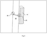
- the first fixing portion 13 is arranged around a part of the outer wall of the pipeline to form a first contact point 21 and a second contact point 22 on the outer wall of the pipeline. There is a height difference between the first contact point 21 and the second contact point 22 to form a self-locking between the counterweight assembly 10 and the pipeline.
- the first fixing portion 13 has a spiral shape.
- the first fixing portion 13 is preferably made of rigid material, such as a metal wire with a smooth surface and an appropriate diameter.
- the first fixing portion 13 could undergo a certain degree of deformation under an external force exerted by an operator so as to facilitate the installation of the counterweight assembly 10 on the outside of the pipeline.
- the length of the first fixing portion 13 is approximately 70% of the circumstance of the outer wall of the pipeline and as a body covers 50% of the circumstance of the outer wall of the pipeline as being bent into a spiral shape.
- the first fixing portion 13 specifically includes a first end 14 and a second end 15 formed higher than the first end 14.
- the first end 14 is provided in the elastic receiving portion 12. An opening is formed between the first end 14 and the second end 15 through which the pipeline penetrates into the elastic receiving portion 12 and is fitted with the elastic receiving portion 12.
- the elastic receiving portion 12 undergoes elastic deformation and the restoring force of the elastic material making of the elastic receiving portion 12 acts on the first end 14 of the first fixing portion 13 to squeeze the first end 14 towards the outer wall of the pipeline forming the first contact point 21.
- the first fixing portion 13 deforms due to the penetration of the pipeline so that the second end 15 is squeezed towards the outer wall of the pipeline forming the second contact point 22.
- the two contact points are respectively formed on both sides of the pipeline, so further the self-locking is formed under the weight to ensure the counterweight assembly 10 could not slide down in usage.
- an elastic limited portion 16 is provided in the elastic receiving portion 12.
- the first end 14 penetrates into the elastic limited portion 16 to form a connection therebetween.
- the elastic receiving portion 12 elastically deforms so as to squeeze the first end 14 towards the outer wall of the pipeline so that the elastic limited portion 16 abuts against the outer wall of the pipeline to form the first contact point 21.
- the first fixing portion 13 further includes an elastic protection component 17.
- the second end 15 is arranged in the elastic protection component 17, the first fixing portion 13 is deformed so that the second end 15 squeezes the outer wall of the pipeline and the elastic protection component 17 abuts against the outer wall of the pipeline to form the second contact point 22.
- the elastic limited portion 16 is preferably formed integrally with the elastic receiving portion 12, and is fixed in a ring shape on a side wall of the elastic receiving portion 12 in contact with the outer wall of the pipeline.
- the first end 14 protrudes from the elastic receiving portion 12 and is fixed.
- the elastic protection component 17 is preferably an elastic sheath made of a soft material, and its length is approximately one third of the total length of the first fixing portion 13.
- the elastic protection component 17, the counterweight body 11, and the elastic sheath are made of the same material.
- the relation between three factors including the coefficient of friction of the first contact point 21 and the second contact point 22, the height difference between the first contact point 21 and the second contact point 22 along the extended direction of the pipeline, and a distance between the center of gravity of the counterweight body 11 and the center of the pipeline could ensure the self-locking effect.
- the coefficient of friction of the soft material which is selected to make the elastic protection component 17, the counterweight body 11 and the elastic sheath could be retrieved, namely the coefficient of friction ⁇ of the first contact point 21 and the second contact point 22, and it is further to determine the distance x between the center of gravity of the counterweight body 11 and the center of the pipeline, and it is further to determine the height difference h between the first contact point 21 and the second contact point 22.
- the self-locking effect could be regulated by only adjusting the height difference between the first contact point 21 and the second contact point 22 along the extended direction of the pipeline on the basis of the known coefficient of friction and the distance between the center of gravity of the counterweight body 11 and the center of the pipeline as the counterweight assembly 10 is being arranged.
- the installation operation is simplified due to there is only one constraint condition which is in a range that the height difference should be satisfied.
- the center of gravity of the counterweight body 11 could be obtained by computer simulation once the shape and weight of the counterweight body 11 is determined.
- a second fixing portion 19 is also provided.
- the second fixing portion 19 is arranged around the outer wall of the pipeline.
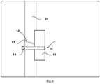
- One side of the counterweight body 11 away from the elastic receiving portion 12 is formed an annular groove 18, and the second fixing portion 19 penetrates through the annular groove 18 to restrict the relative movement of the pipeline and the counterweight assembly 10 as a whole.
- the second fixing portion 19 is preferably arranged below the first fixing portion 13, and the first fixing portion 13 and the second fixing portion 19 are independent of each other but not interacting.
- the second fixing portion 19 is preferably a wire.
- the air conditioner includes a housing 5 installed inside a room.
- the compressor 2 and an indoor heat exchanger 6 are provided in the housing 5.
- the indoor heat exchanger is configured to exchange heat with air, and alternatively two or more indoor heat exchangers could be disposed and exchange heat with air or other media, such as water and the like.
- the housing 5 shown in Fig. 7 is only provided with the indoor side heat exchanger 6 exchanging heat with air.
- the indoor heat exchanger 6 is arranged at the uppermost of the housing 5, and an indoor fan and the compressor 2 are arranged in sequence from top to bottom.
- the space where the compressor 2 is disposed is more compact and the design space for the pipelines is smaller.
- the counterweight assembly 10 is installed the suction pipeline 3 or the discharge pipeline 4 of the compressor 2.
- the counterweight assembly 10 is used to change the inherent frequency of the pipeline so as to avoid the occurrence of running noise or severe vibration caused by the superposition of the inherent frequency of the pipeline and the operating frequency of the compressor 2.
- the counterweight assembly 10 as shown could be arranged on a pipeline, and is in particular suitable for installing on a pipeline portion extended along the vertical direction.
- the pipeline section 31 has a continuous outer wall extending vertically so that there will be more design space allowing for an elbow pipeline section, and additionally the installation of the counterweight assembly 10 is more flexible, easy to operate, replace and maintain.
- the counterweight assembly 10 mainly comprises a counterweight body 11.
- the counterweight body 11 is made of a soft material with elasticity, or a hard material. If the counterweight body 11 is made of a hard material, a thick soft material should be used to cover its outside to avoid scratching the pipeline. The soft material could be rubber or other composite materials.
- the weight of the counterweight body 11 is preferably obtained through software simulation according to the type of the compressor 2.
- An elastic receiving portion 12 is formed on the counterweight body 11.
- the elastic receiving portion 12 is recessed and formed integrally with the counterweight body 11. In an original state, the cross-sectional area of the elastic receiving portion 12 is smaller than an arc area of a corresponding position on the outer wall of the pipe.
- the pipeline passes through the elastic receiving portion 12 and a part of the outer wall is embedded in the elastic receiving portion 12 in usage.
- the elastic receiving portion 12 When the counterweight assembly 10 is assembled, on one side of the outer wall of the pipeline, the elastic receiving portion 12 correspondingly expands to restrict a relative movement on the outer wall of the pipeline.
- the counterweight assembly 10 further includes a first fixing portion 13.
- the first fixing portion 13 is connected to the elastic receiving portion 12.
- the first fixing portion 13 is arranged around a part of the outer wall of the pipeline to form a first contact point 21 and a second contact point 22 on the outer wall of the pipeline. There is a height difference between the first contact point 21 and the second contact point 22 to form a self-locking between the counterweight assembly 10 and the pipeline.
- the first fixing portion 13 has a spiral shape.
- the first fixing portion 13 is preferably made of rigid material, such as a metal wire with a smooth surface and an appropriate diameter.
- the first fixing portion 13 could undergo a certain degree of deformation under an external force exerted by an operator so as to facilitate the installation of the counterweight assembly 10 on the outside of the pipeline.
- the length of the first fixing portion 13 is approximately 70% of the circumstance of the outer wall of the pipeline and as a body covers 50% of the circumstance of the outer wall of the pipeline as being bent into a spiral shape.
- the first fixing portion 13 specifically includes a first end 14 and a second end 15 formed higher than the first end 14.
- the first end 14 is provided in the elastic receiving portion 12.
- An opening is formed between the first end 14 and the second end 15 through which the pipeline penetrates into the elastic receiving portion 12 and is fitted with the elastic receiving portion 12.
- the elastic receiving portion 12 undergoes elastic deformation and the restoring force of the elastic material making of the elastic receiving portion 12 acts on the first end 14 of the first fixing portion 13 to squeeze the first end 14 toward the outer wall of the pipeline forming the first contact point 21.
- the first fixing portion 13 deforms due to the penetration of the pipeline so that the second end 15 is squeezed towards the outer wall of the pipeline forming the second contact point 22.
- the two contact points are respectively formed on both sides of the pipeline, so further the self-locking is formed under the weight to ensure the counterweight assembly 10 could not slide down in usage.
- the outer of the first fixing portion 13 is covered by soft material and the first fixing portion 13 and the counterweight assembly 10 are preferably integrallyformed.
- the relation between three factors including the coefficient of friction of the first contact point 21 and the second contact point 22, the height difference between the first contact point 21 and the second contact point 22 along the extended direction of the pipeline, and a distance between the center of gravity of the counterweight body 11 and the center of the pipeline could ensure the self-locking effect.
- the coefficient of friction of the soft material which is selected to make the elastic protection component 17, the counterweight body 11 and the elastic sheath could be retrieved, namely the coefficient of friction ⁇ of the first contact point 21 or the second contact point 22, and it is further to determine the distance x between the center of gravity of the counterweight body 11 and the center of the pipeline, and it is further to determine the height difference h between the first contact point 21 and the second contact point 22.
- the self-locking effect could be regulated by only adjusting the height difference between the first contact point 21 and the second contact point 22 along the extended direction of the pipeline on the basis of the known coefficient of friction and the distance between the center of gravity of the counterweight body 11 and the center of the pipeline as the counterweight assembly 10 is being arranged.
- the installation operation is simplified due to there is only one constraint condition which is in a range that the height difference should be satisfied.
- the center of gravity of the counterweight body 11 could be obtained by computer simulation once the shape and weight of the counterweight body 11 is determined.
Landscapes
- Engineering & Computer Science (AREA)
- Chemical & Material Sciences (AREA)
- Combustion & Propulsion (AREA)
- Mechanical Engineering (AREA)
- General Engineering & Computer Science (AREA)
- Compressor (AREA)
- Other Air-Conditioning Systems (AREA)
Abstract
Description
- The invention belongs to the technical field of air conditioning equipment, and in particular relates to an outdoor unit of an air conditioner and an air conditioner.
- The functions of air conditioning system (also referred to air conditioner) is to adjust at least part of parameters of indoor ambient air to their expected ranges in accordance with user's requirements, such as temperature, humidity, flow speed, cleanliness, freshness and the like. An air conditioner mainly includes: a compressor, a cold source or a heat source, an air supply system and an adjustment device. According to different working principles, the air conditioners could be divided into fixed speed air conditioners and inverter air conditioners, wherein the inverter air conditioner is an air conditioning system in which the amount of refrigerant circulated into an indoor unit could be regulated by controlling the amount of refrigerant circulated in the compressor so as to satisfy cooling load or heating load of the air conditioning system in time.
- The amount of refrigerant circulated in the compressor is usually adjusted by controlling the frequency of the compressor; that is to say the compressor may work at different frequencies in a range between 15 Hz to 120Hz. Gaseous refrigerant or gas-liquid refrigerant are flowing in a suction pipeline or in a discharge pipeline of the compressor in which the gaseous portion could be compressed or expanded and become a vibration source with a fixed frequency. However either of the pipelines itself has an inherent vibration frequency, the compressor working at certain frequencies may serve as a vibration source acting on the pipelines and a vibration response may generate when it is superposed on the inherent vibration frequency and further result in low-frequency vibration noise or intense vibration in the air conditioner and affect user's experience.
- In order to solve the problem, rubber blocks are bounded on the pipelines of the compressor by wires to change their inherent vibration frequencies in the prior art. But as the counterweight, the rubber blocks are very likely to fall during the operation of air conditioner and the descent may wrongly change the inherent vibration frequency of the pipelines again resulting in the structure could not able to weaken the vibration.
- Aiming at solve the problem that as the counterweight, the rubber blocks are very likely to fall during the operation of air conditioner and the descent may wrongly change the inherent vibration frequency of the pipelines again resulting in the structure could not able to weaken the vibration, one aspect of the present invention is to provide an air conditioner outdoor unit.
- To achieve the above-mentioned object, the present invention adopts technical solutions as follows.
- An air conditioner outdoor unit including: a compressor; a pipeline through which refrigerant is sucked into or discharge from the compressor; characterized in that the air conditioner outdoor unit further includes: a counterweight assembly including: a counterweight body, which is provided with an elastic receiving portion through which one of the pipeline passes and embedded therein; and a first fixing portion connected to the elastic receiving portion, which is arranged around a part of an outer wall of the pipeline to form a first contact point and a second contact point thereon; wherein the first contact point and the second contact point has a height difference forming a self-locking between the counterweight assembly and the pipeline.
- Further, the first fixing portion is spiral and made of rigid material, which has: a first end connected to the elastic receiving portion; and a second end provided higher than the first end; when the pipeline is embedded in the elastic receiving portion, the elastic receiving portion deforms to squeeze the first end towards the outer wall of the pipeline forming the first contact point and the first fixing portion deforms to squeeze towards the second end towards the outer wall of the pipeline forming the second contact point.
- In order to protect the outer wall of pipeline, an elastic limited portion is provided in the elastic receiving portion, into which the first end is penetrated; wherein the elastic limited portion elastically deforms to squeeze the first end towards the outer wall of the pipeline to enable the elastic limited portion to abut against the outer wall of the pipeline to form the first contact point.
- Further the first fixing portion further includes: an elastic protection component in which the second end is arranged; wherein the first fixing portion deforms to enable the second end to squeeze the outer wall of the pipeline and the elastic protection component abuts against the outer wall of the pipeline to form the second contact point.
- The counterweight assembly is particularly suitable for a vertical pipeline portion and the selflock could prevent it from sliding down, so preferably the pipeline is vertically arranged and has a continuous outer wall extended vertically.
- In order to ensure the self-locking effect in installation, the height difference h between the first contact point and the second contact point satisfying:

- In order to avoid movement caused by collision with people, the air conditioner outdoor unit further includes: a second fixing portion arranged around the outer wall of the pipeline which is arranged below the first fixing portion.
- Further an annular groove is formed on one side of the counterweight body away from the elastic receiving portion and through which the second fixing portion penetrates.
- Another aspect of the present invention provides an air conditioner including: a housing installed indoor in which a compressor and one or more heat exchangers are provided; and a pipeline through which refrigerant is sucked into or discharge from the compressor; the air conditioner outdoor unit further includes: a counterweight assembly including: a counterweight body, which is provided with an elastic receiving portion through which one of the pipeline passes and embedded therein; and a first fixing portion connected to the elastic receiving portion, which is arranged around a part of an outer wall of the pipeline to form a first contact point and a second contact point thereon; wherein the first contact point and the second contact point has a height difference forming a self-locking between the counterweight assembly and the pipeline.
- Further the first fixing portion is spiral and made of rigid material, which has: a first end connected to the elastic receiving portion; and a second end provided higher than the first end; when the pipeline is embedded in the elastic receiving portion, the elastic receiving portion deforms to squeeze the first end towards the outer wall of the pipeline forming the first contact point and the first fixing portion deforms to squeeze towards the second end towards the outer wall of the pipeline forming the second contact point; and the height difference h between the first contact point and the second contact point satisfying:

- Compared with the prior art, the advantages and positive effects of the present invention are:
Due to the height difference between the first contact point and the second contact point, a self-locking between the counterweight assembly and the pipeline is formed under the weight of the counterweight body and the counterweight body cannot move downwards during operation for a long period of time even being installed on the pipeline section vertically extended, thereby avoiding a resonation between the inherent frequency of the pipeline and that of the operation of the compressor, and the stability performance of the air conditioner is improved. - After reading the specific embodiments of the present invention in conjunction with the accompanying drawings, other features and advantages of the present invention will become clearer.
- In order to clearly explain embodiments of the present invention or technical solutions in the prior art, at first drawings related to description of the embodiments or the prior art will be briefly introduced as follows. It is obvious that the drawings are described here are part of embodiments of the present invention; for those ordinary skill in the art other drawings could be obtained based on these without any creative work.
-
Fig.1 is a schematic structural diagram of an air conditioner outdoor unit according to one aspect of the present invention; -
Fig.2 is a schematic diagram of the structure when the counterweight assembly is arranged on the pipeline; -
Fig.3 is a schematic diagram of the counterweight assembly shown inFig. 2 ; -
Fig.4 is a schematic diagram of the first contact point and the second contact point when the counterweight assembly is arranged on the pipeline shown inFig.3 ; -
Fig.5 shows a positional relationship between the height difference between the first contact point and the second contact point along the extension of the pipeline, the distance between the center of gravity of the counterweight body and the center of the pipeline when the counterweight assembly is arranged on the pipeline as shown inFig.4 -
Fig.6 is a schematic structural diagram of the first fixing part, the second fixing portion and the pipeline in installation; -
Fig.7 is a schematic structural diagram of an air conditioner according to another aspect of the present invention. - In order to make the objectives, technical solutions, and advantages of the present invention clearer, the following will further describe the present invention in detail with reference to the accompanying drawings and embodiments.
- It should be noted that in the description of the present invention, the terms "upper", "lower", "left", "right", "vertical", "horizontal", "inner", "outer", etc. indicating directions or positions are merely based on the direction or position relationship shown in the drawings, which is only for description, and does not indicate or imply that the device or element must have a specific orientation, be constructed and operated in a specific orientation, and therefore could not be understood as restrictions of the present invention. In addition, the terms "first" and "second" are only used for description and could not be understood as indicating or implying relative importance.
-
Fig.1 is a schematic structural diagram of an outdoor unit of an air conditioner according to one aspect of the present invention. The air conditioneroutdoor unit 1 includes acompressor 2 and pipelines connected to, wherein the pipelines specifically refer to asuction pipeline 3 and adischarge pipeline 4 which communicate with thecompressor 2, refrigerant in thesuction pipeline 3 is sucked into thecompressor 2 and discharged from thecompressor 2 to thedischarge pipeline 4. Theoutdoor unit 1 is provided with an air inlet and an air outlet. The outdoor unit may also be provided with components such as a heat exchanger, an axial flow fan and its motor, a throttling device and a four-way valve.Compressor 2 could be a fixed frequency compressor directly powered by 220V/50Hz mains supply with a theoretical speed 3000r/min and an actual speed 2800r/min due to factors as resistance during operation. More commonly thecompressor 2 is an inverter compressor powered by analog three-phase AC output from an inverter module with an allowable frequency range from 15Hz to 120Hz and an allowable voltage range from 30V to 200V, and the compressor speed is in a range from 1500r/min to 9000r/min. Taking a cooling mode as an example, when the compressor speed increases, the cooling capacity increases accordingly and the cooling effect is intensified so that the room temperature drops rapidly; the compressor speeds decreases when the room temperature drops to a point near a target temperature to maintain the room temperature. As peripheral pipelines of thecompressor 2, it is necessary to consider a plurality of factors in designing thesuction pipeline 3 and thedischarge pipeline 4 such as refrigerant resistance, noise, installation of auxiliary filters, arrangement of gas-liquid separator, position of nozzles shape of casing and the like, so the design space for thesuction pipeline 3 and thedischarge pipeline 4 is strictly restricted and it is better to bend as little as possible. Thecompressor 2 is provided at the bottom of the air conditioneroutdoor unit 1 as shown inFig.1 . It should be noted that the arrangement of the compressor is not limited as shown inFig.1 and it could be arranged at other positions of the air conditioneroutdoor unit 1 by adjusting thesuction pipeline 3, thedischarge pipeline 4 and the internal layout of the casing. - Specifically, as shown in
Fig.2 , acounterweight assembly 10 is provided on a pipeline and the inherent frequency of the pipeline is changed by arranging thecounterweight assembly 10 to avoid operating noise or intense vibration caused by specific operating frequencies of the compressor superposed on the inherent frequency of the pipeline. As shown inFig.3 , thecounterweight assembly 10 could be disposed at any position of the pipeline and is preferably installed on a section of a pipeline vertically arranged, as apipeline section 31 shown inFig.2 . The pipeline section, such as thepipeline section 31, has a continuous outer wall extending vertically so that there will be more design space allowing for an elbow pipeline section, and additionally the installation of thecounterweight assembly 10 is more flexible, easy to operate, replace and maintain. As shown inFig.3 , thecounterweight assembly 10 mainly comprises acounterweight body 11. Thecounterweight body 11 is made of a soft material with elasticity, or a hard material. If thecounterweight body 11 is made of a hard material, a thick soft material should be used to cover its outside to avoid scratching the pipeline. The soft material could be rubber or other composite materials. The weight of thecounterweight body 11 is preferably obtained through software simulation according to the type of thecompressor 2. - An
elastic receiving portion 12 is formed on thecounterweight body 11. Theelastic receiving portion 12 is recessed and formed integrally with thecounterweight body 11. In an original state, the cross-sectional area of theelastic receiving portion 12 is smaller than an arc area of a corresponding position on the outer wall of the pipe. The pipeline passes through the elastic receivingportion 12 and a part of the outer wall is embedded in the elastic receivingportion 12 in usage. When thecounterweight assembly 10 is assembled, on one side of the outer wall of the pipeline, theelastic receiving portion 12 correspondingly expands to restrict a relative movement on the outer wall of the pipeline. - The
counterweight assembly 10 further includes afirst fixing portion 13. Thefirst fixing portion 13 is connected to the elastic receivingportion 12. Thefirst fixing portion 13 is arranged around a part of the outer wall of the pipeline to form afirst contact point 21 and asecond contact point 22 on the outer wall of the pipeline. There is a height difference between thefirst contact point 21 and thesecond contact point 22 to form a self-locking between thecounterweight assembly 10 and the pipeline. - Due to the height difference between the
first contact point 21 and thesecond contact point 22, a self-locking between thecounterweight assembly 10 and the pipeline is formed under the weight of thecounterweight body 11 and thecounterweight body 11 cannot move downwards during operation for a long period of time even being installed on thepipeline section 31 vertically extended, thereby avoiding a resonation between the inherent frequency of the pipeline and that of the operation of the compressor, and the stability performance of the air conditioner is improved. - A preferred structure of the
counterweight assembly 10 is further described with reference toFig.3 to Fig.5 as follows. As shown inFig.3 , the first fixingportion 13 has a spiral shape. Thefirst fixing portion 13 is preferably made of rigid material, such as a metal wire with a smooth surface and an appropriate diameter. Thefirst fixing portion 13 could undergo a certain degree of deformation under an external force exerted by an operator so as to facilitate the installation of thecounterweight assembly 10 on the outside of the pipeline. The length of the first fixingportion 13 is approximately 70% of the circumstance of the outer wall of the pipeline and as a body covers 50% of the circumstance of the outer wall of the pipeline as being bent into a spiral shape. Thefirst fixing portion 13 specifically includes afirst end 14 and asecond end 15 formed higher than thefirst end 14. Thefirst end 14 is provided in the elastic receivingportion 12. An opening is formed between thefirst end 14 and thesecond end 15 through which the pipeline penetrates into the elastic receivingportion 12 and is fitted with the elastic receivingportion 12. When the pipeline is embedded in the elastic receivingportion 12, the elastic receivingportion 12 undergoes elastic deformation and the restoring force of the elastic material making of the elastic receivingportion 12 acts on thefirst end 14 of the first fixingportion 13 to squeeze thefirst end 14 towards the outer wall of the pipeline forming thefirst contact point 21. On the other side, the first fixingportion 13 deforms due to the penetration of the pipeline so that thesecond end 15 is squeezed towards the outer wall of the pipeline forming thesecond contact point 22. With this arrangements the two contact points are respectively formed on both sides of the pipeline, so further the self-locking is formed under the weight to ensure thecounterweight assembly 10 could not slide down in usage. - In order to keep the coefficient of friction of the
first contact point 21 and thesecond contact point 22 in a proper range so as to ensure the self-locking reliably functions, and further to protect the outer wall of the pipeline in the meanwhile, an elasticlimited portion 16 is provided in the elastic receivingportion 12. Thefirst end 14 penetrates into the elasticlimited portion 16 to form a connection therebetween. Theelastic receiving portion 12 elastically deforms so as to squeeze thefirst end 14 towards the outer wall of the pipeline so that the elasticlimited portion 16 abuts against the outer wall of the pipeline to form thefirst contact point 21. At the other end, for the same purpose, the first fixingportion 13 further includes anelastic protection component 17. Thesecond end 15 is arranged in theelastic protection component 17, the first fixingportion 13 is deformed so that thesecond end 15 squeezes the outer wall of the pipeline and theelastic protection component 17 abuts against the outer wall of the pipeline to form thesecond contact point 22. The elasticlimited portion 16 is preferably formed integrally with the elastic receivingportion 12, and is fixed in a ring shape on a side wall of the elastic receivingportion 12 in contact with the outer wall of the pipeline. Thefirst end 14 protrudes from the elastic receivingportion 12 and is fixed. Theelastic protection component 17 is preferably an elastic sheath made of a soft material, and its length is approximately one third of the total length of the first fixingportion 13. Preferably, theelastic protection component 17, thecounterweight body 11, and the elastic sheath are made of the same material. - The relation between three factors including the coefficient of friction of the
first contact point 21 and thesecond contact point 22, the height difference between thefirst contact point 21 and thesecond contact point 22 along the extended direction of the pipeline, and a distance between the center of gravity of thecounterweight body 11 and the center of the pipeline could ensure the self-locking effect. To be specific, the coefficient of friction of the soft material which is selected to make theelastic protection component 17, thecounterweight body 11 and the elastic sheath could be retrieved, namely the coefficient of friction µ of thefirst contact point 21 and thesecond contact point 22, and it is further to determine the distance x between the center of gravity of thecounterweight body 11 and the center of the pipeline, and it is further to determine the height difference h between thefirst contact point 21 and thesecond contact point 22. The three factors satisfy a condition of µ > h/ 2x. Hence the self-locking effect could be regulated by only adjusting the height difference between thefirst contact point 21 and thesecond contact point 22 along the extended direction of the pipeline on the basis of the known coefficient of friction and the distance between the center of gravity of thecounterweight body 11 and the center of the pipeline as thecounterweight assembly 10 is being arranged. The installation operation is simplified due to there is only one constraint condition which is in a range that the height difference should be satisfied. The center of gravity of thecounterweight body 11 could be obtained by computer simulation once the shape and weight of thecounterweight body 11 is determined. - Considering that the packaging of the air conditioner
outdoor unit 1 may collide during in transportation or during installation, preferably asecond fixing portion 19 is also provided. Thesecond fixing portion 19 is arranged around the outer wall of the pipeline. One side of thecounterweight body 11 away from the elastic receivingportion 12 is formed anannular groove 18, and the second fixingportion 19 penetrates through theannular groove 18 to restrict the relative movement of the pipeline and thecounterweight assembly 10 as a whole. Thesecond fixing portion 19 is preferably arranged below the first fixingportion 13, and the first fixingportion 13 and the second fixingportion 19 are independent of each other but not interacting. Thesecond fixing portion 19 is preferably a wire. - Another aspect of the present invention also discloses an air conditioner. The air conditioner includes a
housing 5 installed inside a room. Thecompressor 2 and anindoor heat exchanger 6 are provided in thehousing 5. The indoor heat exchanger is configured to exchange heat with air, and alternatively two or more indoor heat exchangers could be disposed and exchange heat with air or other media, such as water and the like. Thehousing 5 shown inFig. 7 is only provided with the indoorside heat exchanger 6 exchanging heat with air. Theindoor heat exchanger 6 is arranged at the uppermost of thehousing 5, and an indoor fan and thecompressor 2 are arranged in sequence from top to bottom. In this type of air conditioner, the space where thecompressor 2 is disposed is more compact and the design space for the pipelines is smaller. In order to achieve the effect of shock absorption, thecounterweight assembly 10 is installed thesuction pipeline 3 or thedischarge pipeline 4 of thecompressor 2. - As shown in
Fig.3 to Fig. 5 , in this type of the air conditioner thecounterweight assembly 10 is used to change the inherent frequency of the pipeline so as to avoid the occurrence of running noise or severe vibration caused by the superposition of the inherent frequency of the pipeline and the operating frequency of thecompressor 2. Thecounterweight assembly 10 as shown could be arranged on a pipeline, and is in particular suitable for installing on a pipeline portion extended along the vertical direction. Thepipeline section 31 has a continuous outer wall extending vertically so that there will be more design space allowing for an elbow pipeline section, and additionally the installation of thecounterweight assembly 10 is more flexible, easy to operate, replace and maintain. As shown inFig.3 , thecounterweight assembly 10 mainly comprises acounterweight body 11. Thecounterweight body 11 is made of a soft material with elasticity, or a hard material. If thecounterweight body 11 is made of a hard material, a thick soft material should be used to cover its outside to avoid scratching the pipeline. The soft material could be rubber or other composite materials. The weight of thecounterweight body 11 is preferably obtained through software simulation according to the type of thecompressor 2. - An elastic receiving
portion 12 is formed on thecounterweight body 11. Theelastic receiving portion 12 is recessed and formed integrally with thecounterweight body 11. In an original state, the cross-sectional area of the elastic receivingportion 12 is smaller than an arc area of a corresponding position on the outer wall of the pipe. The pipeline passes through the elastic receivingportion 12 and a part of the outer wall is embedded in the elastic receivingportion 12 in usage. When thecounterweight assembly 10 is assembled, on one side of the outer wall of the pipeline, the elastic receivingportion 12 correspondingly expands to restrict a relative movement on the outer wall of the pipeline. - The
counterweight assembly 10 further includes a first fixingportion 13. Thefirst fixing portion 13 is connected to the elastic receivingportion 12. Thefirst fixing portion 13 is arranged around a part of the outer wall of the pipeline to form afirst contact point 21 and asecond contact point 22 on the outer wall of the pipeline. There is a height difference between thefirst contact point 21 and thesecond contact point 22 to form a self-locking between thecounterweight assembly 10 and the pipeline. - Due to the height difference between the
first contact point 21 and thesecond contact point 22, a self-locking between thecounterweight assembly 10 and the pipeline is formed under the weight of thecounterweight body 11 and thecounterweight body 11 cannot move downwards during operation for a long period of time even being installed on thepipeline section 31 vertically extended, thereby avoiding a resonation between the inherent frequency of the pipeline and that of the operation of the compressor, and the stability performance of the air conditioner is improved. - The
first fixing portion 13 has a spiral shape. Thefirst fixing portion 13 is preferably made of rigid material, such as a metal wire with a smooth surface and an appropriate diameter. Thefirst fixing portion 13 could undergo a certain degree of deformation under an external force exerted by an operator so as to facilitate the installation of thecounterweight assembly 10 on the outside of the pipeline. The length of the first fixingportion 13 is approximately 70% of the circumstance of the outer wall of the pipeline and as a body covers 50% of the circumstance of the outer wall of the pipeline as being bent into a spiral shape. Thefirst fixing portion 13 specifically includes afirst end 14 and asecond end 15 formed higher than thefirst end 14. Thefirst end 14 is provided in the elastic receivingportion 12. An opening is formed between thefirst end 14 and thesecond end 15 through which the pipeline penetrates into the elastic receivingportion 12 and is fitted with the elastic receivingportion 12. When the pipeline is embedded in the elastic receivingportion 12, the elastic receivingportion 12 undergoes elastic deformation and the restoring force of the elastic material making of the elastic receivingportion 12 acts on thefirst end 14 of the first fixingportion 13 to squeeze thefirst end 14 toward the outer wall of the pipeline forming thefirst contact point 21. On the other side, the first fixingportion 13 deforms due to the penetration of the pipeline so that thesecond end 15 is squeezed towards the outer wall of the pipeline forming thesecond contact point 22. With this arrangements the two contact points are respectively formed on both sides of the pipeline, so further the self-locking is formed under the weight to ensure thecounterweight assembly 10 could not slide down in usage. The outer of the first fixingportion 13 is covered by soft material and the first fixingportion 13 and thecounterweight assembly 10 are preferably integrallyformed. - The relation between three factors including the coefficient of friction of the
first contact point 21 and thesecond contact point 22, the height difference between thefirst contact point 21 and thesecond contact point 22 along the extended direction of the pipeline, and a distance between the center of gravity of thecounterweight body 11 and the center of the pipeline could ensure the self-locking effect. To be specific, the coefficient of friction of the soft material which is selected to make theelastic protection component 17, thecounterweight body 11 and the elastic sheath could be retrieved, namely the coefficient of friction µ of thefirst contact point 21 or thesecond contact point 22, and it is further to determine the distance x between the center of gravity of thecounterweight body 11 and the center of the pipeline, and it is further to determine the height difference h between thefirst contact point 21 and thesecond contact point 22. The three factors satisfy a condition of µ > h/2x. Hence the self-locking effect could be regulated by only adjusting the height difference between thefirst contact point 21 and thesecond contact point 22 along the extended direction of the pipeline on the basis of the known coefficient of friction and the distance between the center of gravity of thecounterweight body 11 and the center of the pipeline as thecounterweight assembly 10 is being arranged. The installation operation is simplified due to there is only one constraint condition which is in a range that the height difference should be satisfied. The center of gravity of thecounterweight body 11 could be obtained by computer simulation once the shape and weight of thecounterweight body 11 is determined. - The above embodiments are only used to illustrate the technical solutions of the present invention, but not to limit them; although the present invention has been described in detail with reference to the foregoing embodiments, for those of ordinary skill in the art, the technical solutions of the foregoing embodiments can still be described. The recorded technical solutions are modified, or some of the technical features are equivalently replaced; these modifications or replacements do not cause the essence of the corresponding technical solutions to deviate from the spirit and scope of the technical solutions claimed by the present invention.
Claims (10)
- An air conditioner outdoor unit including:a compressor;a pipeline through which refrigerant is sucked into or discharge from the compressor;characterized in that the air conditioner outdoor unit further includes:a counterweight assembly including:a counterweight body, which is provided with an elastic receiving portion through which one of the pipeline passes and embedded therein; anda first fixing portion connected to the elastic receiving portion, which is arranged around a part of an outer wall of the pipeline to form a first contact point and a second contact point thereon;wherein the first contact point and the second contact point has a height difference forming a self-locking between the counterweight assembly and the pipeline.
- The air conditioner outdoor unit according to claim 1, characterized in that:
the first fixing portion is spiral and made of rigid material, which has:a first end connected to the elastic receiving portion; anda second end provided higher than the first end;when the pipeline is embedded in the elastic receiving portion, the elastic receiving portion deforms to squeeze the first end towards the outer wall of the pipeline forming the first contact point and the first fixing portion deforms to squeeze towards the second end towards the outer wall of the pipeline forming the second contact point. - The air conditioner outdoor unit according to claim 2, characterized in that:an elastic limited portion is provided in the elastic receiving portion, into which the first end is penetrated;wherein the elastic limited portion elastically deforms to squeeze the first end towards the outer wall of the pipeline to enable the elastic limited portion to abut against the outer wall of the pipeline to form the first contact point.
- The air conditioner outdoor unit according to claim 3, characterized in that:the first fixing portion further includes:
an elastic protection component in which the second end is arranged;wherein the first fixing portion deforms to enable the second end to squeeze the outer wall of the pipeline and the elastic protection component abuts against the outer wall of the pipeline to form the second contact point. - The air conditioner outdoor unit according to claim 4, characterized in that:
the pipeline is vertically arranged and has a continuous outer wall extended vertically. - The air conditioner outdoor unit according to claim 5, characterized in that:
the height difference h between the first contact point and the second contact point satisfying:
- The air conditioner outdoor unit according to any one of claim 1 to 6, characterized in that:
the air conditioner outdoor unit further includes:
a second fixing portion arranged around the outer wall of the pipeline which is arranged below the first fixing portion. - The air conditioner outdoor unit according to claim 7, characterized in that:
an annular groove is formed on one side of the counterweight body away from the elastic receiving portion and through which the second fixing portion penetrates. - An air conditioner including:a housing installed indoor in which a compressor and one or more heat exchangers are provided; anda pipeline through which refrigerant is sucked into or discharge from the compressor;characterized in that the air conditioner outdoor unit further includes:a counterweight assembly including:a counterweight body, which is provided with an elastic receiving portion through which one of the pipeline passes and embedded therein; anda first fixing portion connected to the elastic receiving portion, which is arranged around a part of an outer wall of the pipeline to form a first contact point and a second contact point thereon;wherein the first contact point and the second contact point has a height difference forming a self-locking between the counterweight assembly and the pipeline.
- An air conditioner according to claim 9, characterized in that, the first fixing portion is spiral and made of rigid material, which has:a first end connected to the elastic receiving portion; anda second end provided higher than the first end;when the pipeline is embedded in the elastic receiving portion, the elastic receiving portion deforms to squeeze the first end towards the outer wall of the pipeline forming the first contact point and the first fixing portion deforms to squeeze towards the second end towards the outer wall of the pipeline forming the second contact point; andthe height difference h between the first contact point and the second contact point satisfying:
 wherein µ is the coefficient of friction of the first contact point or the second contact point, x is the distance between the center of gravity of the counterweight body and the center of the pipeline.
Applications Claiming Priority (2)
| Application Number | Priority Date | Filing Date | Title |
|---|---|---|---|
| CN201911088707.1A CN112781117B (en) | 2019-11-08 | 2019-11-08 | Outdoor unit of air conditioner and air conditioner |
| PCT/CN2020/080139 WO2021088295A1 (en) | 2019-11-08 | 2020-03-19 | Air conditioner outdoor unit and air conditioner |
Publications (3)
| Publication Number | Publication Date |
|---|---|
| EP3967947A1 true EP3967947A1 (en) | 2022-03-16 |
| EP3967947A4 EP3967947A4 (en) | 2022-08-17 |
| EP3967947B1 EP3967947B1 (en) | 2025-06-11 |
Family
ID=75748946
Family Applications (1)
| Application Number | Title | Priority Date | Filing Date |
|---|---|---|---|
| EP20884108.0A Active EP3967947B1 (en) | 2019-11-08 | 2020-03-19 | Air conditioner outdoor unit and air conditioner |
Country Status (3)
| Country | Link |
|---|---|
| EP (1) | EP3967947B1 (en) |
| CN (1) | CN112781117B (en) |
| WO (1) | WO2021088295A1 (en) |
Families Citing this family (2)
| Publication number | Priority date | Publication date | Assignee | Title |
|---|---|---|---|---|
| CN115234737A (en) * | 2022-06-10 | 2022-10-25 | 青岛海尔空调器有限总公司 | Pipeline buffering device and compressor pipeline buffering control method |
| CN115420373B (en) * | 2022-08-08 | 2025-05-09 | 珠海三友环境技术有限公司 | A calculation method for selecting counterweight blocks for air conditioning exhaust pipes |
Family Cites Families (16)
| Publication number | Priority date | Publication date | Assignee | Title |
|---|---|---|---|---|
| KR20020006865A (en) * | 2000-07-13 | 2002-01-26 | 구자홍 | Vibration-blocking apparatus for pipe of airconditioner |
| KR100677887B1 (en) * | 2005-09-26 | 2007-02-05 | 삼성전자주식회사 | Pipe dustproof device of air conditioner |
| KR100714292B1 (en) * | 2005-09-27 | 2007-05-02 | 삼성전자주식회사 | Pipe dustproof device of air conditioner |
| CN102080871A (en) * | 2009-11-30 | 2011-06-01 | 乐金电子(天津)电器有限公司 | Shock-absorbing wheel for fixing copper tube of air-conditioning outdoor unit |
| CN102798199A (en) * | 2011-05-24 | 2012-11-28 | 乐金电子(天津)电器有限公司 | Copper pipe shock absorption block |
| KR20130048816A (en) * | 2011-11-03 | 2013-05-13 | 삼성전자주식회사 | Damper for decreasing a piping vibration |
| CN103851113A (en) * | 2012-12-04 | 2014-06-11 | 苏州三星电子有限公司 | Dynamic shock-absorbing rubber block |
| CN204063510U (en) * | 2014-07-09 | 2014-12-31 | 神龙汽车有限公司 | A kind of air-conditioning duct noise reducing apparatus |
| CN204553684U (en) * | 2014-12-18 | 2015-08-12 | Tcl空调器(中山)有限公司 | Balancing weight and air conditioner |
| CN204628942U (en) * | 2015-05-15 | 2015-09-09 | 广东美的制冷设备有限公司 | Pipeline balancing weight and the air conditioner with it |
| CN105202649A (en) * | 2015-10-26 | 2015-12-30 | 珠海格力电器股份有限公司 | Compressor pipeline assembly, compressor and air conditioner |
| MX2018006022A (en) * | 2015-11-18 | 2018-08-01 | Kotobuki Sangyo | Refrigerant processing device and refrigeration air conditioning system. |
| CN105571103B (en) * | 2015-12-31 | 2018-08-21 | 山东一村空调有限公司 | A kind of mute noise reducing type geothermal heat pump air-conditioner |
| CN107940710A (en) * | 2017-12-21 | 2018-04-20 | 广东美的暖通设备有限公司 | The balance weight assembly that is located on the pipeline of air conditioner and there is its air conditioner |
| KR102047306B1 (en) * | 2018-01-04 | 2019-11-21 | 엘지전자 주식회사 | A Damper for Reducing Noise and Vibration and a Clamping Structure thereof |
| CN208804155U (en) * | 2018-06-29 | 2019-04-30 | 广东美的暖通设备有限公司 | The vibration absorber and air conditioner of pipeline |
-
2019
- 2019-11-08 CN CN201911088707.1A patent/CN112781117B/en active Active
-
2020
- 2020-03-19 WO PCT/CN2020/080139 patent/WO2021088295A1/en not_active Ceased
- 2020-03-19 EP EP20884108.0A patent/EP3967947B1/en active Active
Also Published As
| Publication number | Publication date |
|---|---|
| WO2021088295A1 (en) | 2021-05-14 |
| EP3967947A4 (en) | 2022-08-17 |
| CN112781117A (en) | 2021-05-11 |
| EP3967947B1 (en) | 2025-06-11 |
| CN112781117B (en) | 2022-04-22 |
Similar Documents
| Publication | Publication Date | Title |
|---|---|---|
| EP2054671B1 (en) | Water-cooled air conditioner | |
| EP2333435A2 (en) | Bell-mouth structure of air blower | |
| EP3967947B1 (en) | Air conditioner outdoor unit and air conditioner | |
| US20250020373A1 (en) | Refrigeration cycle apparatus | |
| KR102063525B1 (en) | Window type airconditioner | |
| EP1243864B1 (en) | Indoor unit and air-conditioner | |
| US20230392613A1 (en) | Bracket assembly for an hvac system | |
| US20250383100A1 (en) | Sound and vibration damping enclosures for refrigerant compressors of climate control systems | |
| EP1114969B1 (en) | Power controllable type air conditioner | |
| EP2096365A1 (en) | Heat source unit installed inside building | |
| JPS61128075A (en) | Refrigeration cycle | |
| CN111412541A (en) | Multifunctional integrated air conditioner | |
| CN101592363B (en) | Split type outdoor unit of air conditioner | |
| JP2018087698A (en) | Heat source unit | |
| CN102080871A (en) | Shock-absorbing wheel for fixing copper tube of air-conditioning outdoor unit | |
| KR100512240B1 (en) | The forming structure of base plate using air conditioner outdoor unit | |
| KR20170064255A (en) | Outdoor unit of airconditioner | |
| CN117190323A (en) | Air conditioner | |
| JP3075887B2 (en) | Air conditioner | |
| JP3257753B2 (en) | Air conditioner | |
| CN207471729U (en) | Modular air conditioner | |
| CN120426600A (en) | Compressor integrated system, air conditioning outdoor unit and HVAC equipment | |
| CN219727784U (en) | Compact vehicle air conditioner assembly and vehicle | |
| CN218495434U (en) | Throttling assembly of air conditioner, air conditioner indoor unit and air conditioner | |
| JP7460925B1 (en) | Air conditioning equipment and component units |
Legal Events
| Date | Code | Title | Description |
|---|---|---|---|
| STAA | Information on the status of an ep patent application or granted ep patent |
Free format text: STATUS: THE INTERNATIONAL PUBLICATION HAS BEEN MADE |
|
| PUAI | Public reference made under article 153(3) epc to a published international application that has entered the european phase |
Free format text: ORIGINAL CODE: 0009012 |
|
| STAA | Information on the status of an ep patent application or granted ep patent |
Free format text: STATUS: REQUEST FOR EXAMINATION WAS MADE |
|
| 17P | Request for examination filed |
Effective date: 20211210 |
|
| AK | Designated contracting states |
Kind code of ref document: A1 Designated state(s): AL AT BE BG CH CY CZ DE DK EE ES FI FR GB GR HR HU IE IS IT LI LT LU LV MC MK MT NL NO PL PT RO RS SE SI SK SM TR |
|
| A4 | Supplementary search report drawn up and despatched |
Effective date: 20220720 |
|
| RIC1 | Information provided on ipc code assigned before grant |
Ipc: F24F 13/24 20060101AFI20220714BHEP |
|
| DAV | Request for validation of the european patent (deleted) | ||
| DAX | Request for extension of the european patent (deleted) | ||
| REG | Reference to a national code |
Ref country code: DE Ref legal event code: R079 Free format text: PREVIOUS MAIN CLASS: F24F0013240000 Ipc: F24F0001120000 Ref country code: DE Ref legal event code: R079 Ref document number: 602020052750 Country of ref document: DE Free format text: PREVIOUS MAIN CLASS: F24F0013240000 Ipc: F24F0001120000 |
|
| GRAP | Despatch of communication of intention to grant a patent |
Free format text: ORIGINAL CODE: EPIDOSNIGR1 |
|
| STAA | Information on the status of an ep patent application or granted ep patent |
Free format text: STATUS: GRANT OF PATENT IS INTENDED |
|
| RIC1 | Information provided on ipc code assigned before grant |
Ipc: F24F 1/46 20110101ALI20241210BHEP Ipc: F24F 1/12 20110101AFI20241210BHEP |
|
| INTG | Intention to grant announced |
Effective date: 20250115 |
|
| GRAS | Grant fee paid |
Free format text: ORIGINAL CODE: EPIDOSNIGR3 |
|
| GRAA | (expected) grant |
Free format text: ORIGINAL CODE: 0009210 |
|
| STAA | Information on the status of an ep patent application or granted ep patent |
Free format text: STATUS: THE PATENT HAS BEEN GRANTED |
|
| AK | Designated contracting states |
Kind code of ref document: B1 Designated state(s): AL AT BE BG CH CY CZ DE DK EE ES FI FR GB GR HR HU IE IS IT LI LT LU LV MC MK MT NL NO PL PT RO RS SE SI SK SM TR |
|
| REG | Reference to a national code |
Ref country code: GB Ref legal event code: FG4D |
|
| REG | Reference to a national code |
Ref country code: CH Ref legal event code: EP |
|
| REG | Reference to a national code |
Ref country code: IE Ref legal event code: FG4D |
|
| REG | Reference to a national code |
Ref country code: DE Ref legal event code: R096 Ref document number: 602020052750 Country of ref document: DE |
|
| PG25 | Lapsed in a contracting state [announced via postgrant information from national office to epo] |
Ref country code: ES Free format text: LAPSE BECAUSE OF FAILURE TO SUBMIT A TRANSLATION OF THE DESCRIPTION OR TO PAY THE FEE WITHIN THE PRESCRIBED TIME-LIMIT Effective date: 20250611 Ref country code: FI Free format text: LAPSE BECAUSE OF FAILURE TO SUBMIT A TRANSLATION OF THE DESCRIPTION OR TO PAY THE FEE WITHIN THE PRESCRIBED TIME-LIMIT Effective date: 20250611 |
|
| REG | Reference to a national code |
Ref country code: LT Ref legal event code: MG9D |
|
| PG25 | Lapsed in a contracting state [announced via postgrant information from national office to epo] |
Ref country code: NO Free format text: LAPSE BECAUSE OF FAILURE TO SUBMIT A TRANSLATION OF THE DESCRIPTION OR TO PAY THE FEE WITHIN THE PRESCRIBED TIME-LIMIT Effective date: 20250911 Ref country code: GR Free format text: LAPSE BECAUSE OF FAILURE TO SUBMIT A TRANSLATION OF THE DESCRIPTION OR TO PAY THE FEE WITHIN THE PRESCRIBED TIME-LIMIT Effective date: 20250912 |
|
| REG | Reference to a national code |
Ref country code: NL Ref legal event code: MP Effective date: 20250611 |
|
| PG25 | Lapsed in a contracting state [announced via postgrant information from national office to epo] |
Ref country code: BG Free format text: LAPSE BECAUSE OF FAILURE TO SUBMIT A TRANSLATION OF THE DESCRIPTION OR TO PAY THE FEE WITHIN THE PRESCRIBED TIME-LIMIT Effective date: 20250611 |
|
| PG25 | Lapsed in a contracting state [announced via postgrant information from national office to epo] |
Ref country code: HR Free format text: LAPSE BECAUSE OF FAILURE TO SUBMIT A TRANSLATION OF THE DESCRIPTION OR TO PAY THE FEE WITHIN THE PRESCRIBED TIME-LIMIT Effective date: 20250611 |
|
| PG25 | Lapsed in a contracting state [announced via postgrant information from national office to epo] |
Ref country code: RS Free format text: LAPSE BECAUSE OF FAILURE TO SUBMIT A TRANSLATION OF THE DESCRIPTION OR TO PAY THE FEE WITHIN THE PRESCRIBED TIME-LIMIT Effective date: 20250911 |
|
| PG25 | Lapsed in a contracting state [announced via postgrant information from national office to epo] |
Ref country code: LV Free format text: LAPSE BECAUSE OF FAILURE TO SUBMIT A TRANSLATION OF THE DESCRIPTION OR TO PAY THE FEE WITHIN THE PRESCRIBED TIME-LIMIT Effective date: 20250611 |
|
| PG25 | Lapsed in a contracting state [announced via postgrant information from national office to epo] |
Ref country code: NL Free format text: LAPSE BECAUSE OF FAILURE TO SUBMIT A TRANSLATION OF THE DESCRIPTION OR TO PAY THE FEE WITHIN THE PRESCRIBED TIME-LIMIT Effective date: 20250611 |
|
| PG25 | Lapsed in a contracting state [announced via postgrant information from national office to epo] |
Ref country code: PT Free format text: LAPSE BECAUSE OF FAILURE TO SUBMIT A TRANSLATION OF THE DESCRIPTION OR TO PAY THE FEE WITHIN THE PRESCRIBED TIME-LIMIT Effective date: 20251013 |
|
| REG | Reference to a national code |
Ref country code: AT Ref legal event code: MK05 Ref document number: 1802538 Country of ref document: AT Kind code of ref document: T Effective date: 20250611 |
|
| PG25 | Lapsed in a contracting state [announced via postgrant information from national office to epo] |
Ref country code: IS Free format text: LAPSE BECAUSE OF FAILURE TO SUBMIT A TRANSLATION OF THE DESCRIPTION OR TO PAY THE FEE WITHIN THE PRESCRIBED TIME-LIMIT Effective date: 20251011 |
|
| PG25 | Lapsed in a contracting state [announced via postgrant information from national office to epo] |
Ref country code: AT Free format text: LAPSE BECAUSE OF FAILURE TO SUBMIT A TRANSLATION OF THE DESCRIPTION OR TO PAY THE FEE WITHIN THE PRESCRIBED TIME-LIMIT Effective date: 20250611 Ref country code: SM Free format text: LAPSE BECAUSE OF FAILURE TO SUBMIT A TRANSLATION OF THE DESCRIPTION OR TO PAY THE FEE WITHIN THE PRESCRIBED TIME-LIMIT Effective date: 20250611 |
|
| PG25 | Lapsed in a contracting state [announced via postgrant information from national office to epo] |
Ref country code: CZ Free format text: LAPSE BECAUSE OF FAILURE TO SUBMIT A TRANSLATION OF THE DESCRIPTION OR TO PAY THE FEE WITHIN THE PRESCRIBED TIME-LIMIT Effective date: 20250611 |
|
| PG25 | Lapsed in a contracting state [announced via postgrant information from national office to epo] |
Ref country code: PL Free format text: LAPSE BECAUSE OF FAILURE TO SUBMIT A TRANSLATION OF THE DESCRIPTION OR TO PAY THE FEE WITHIN THE PRESCRIBED TIME-LIMIT Effective date: 20250611 |
|
| PG25 | Lapsed in a contracting state [announced via postgrant information from national office to epo] |
Ref country code: EE Free format text: LAPSE BECAUSE OF FAILURE TO SUBMIT A TRANSLATION OF THE DESCRIPTION OR TO PAY THE FEE WITHIN THE PRESCRIBED TIME-LIMIT Effective date: 20250611 |
|
| PG25 | Lapsed in a contracting state [announced via postgrant information from national office to epo] |
Ref country code: SK Free format text: LAPSE BECAUSE OF FAILURE TO SUBMIT A TRANSLATION OF THE DESCRIPTION OR TO PAY THE FEE WITHIN THE PRESCRIBED TIME-LIMIT Effective date: 20250611 Ref country code: RO Free format text: LAPSE BECAUSE OF FAILURE TO SUBMIT A TRANSLATION OF THE DESCRIPTION OR TO PAY THE FEE WITHIN THE PRESCRIBED TIME-LIMIT Effective date: 20250611 |
|
| REG | Reference to a national code |
Ref country code: DE Ref legal event code: R097 Ref document number: 602020052750 Country of ref document: DE |
|
| PGFP | Annual fee paid to national office [announced via postgrant information from national office to epo] |
Ref country code: GB Payment date: 20260324 Year of fee payment: 7 |
|
| PG25 | Lapsed in a contracting state [announced via postgrant information from national office to epo] |
Ref country code: DK Free format text: LAPSE BECAUSE OF FAILURE TO SUBMIT A TRANSLATION OF THE DESCRIPTION OR TO PAY THE FEE WITHIN THE PRESCRIBED TIME-LIMIT Effective date: 20250611 |
|
| PGFP | Annual fee paid to national office [announced via postgrant information from national office to epo] |
Ref country code: DE Payment date: 20260319 Year of fee payment: 7 |
|
| PGFP | Annual fee paid to national office [announced via postgrant information from national office to epo] |
Ref country code: IT Payment date: 20260324 Year of fee payment: 7 |
|
| PLBE | No opposition filed within time limit |
Free format text: ORIGINAL CODE: 0009261 |
|
| STAA | Information on the status of an ep patent application or granted ep patent |
Free format text: STATUS: NO OPPOSITION FILED WITHIN TIME LIMIT |
|
| REG | Reference to a national code |
Ref country code: CH Ref legal event code: L10 Free format text: ST27 STATUS EVENT CODE: U-0-0-L10-L00 (AS PROVIDED BY THE NATIONAL OFFICE) Effective date: 20260423 |
|
| 26N | No opposition filed |
Effective date: 20260312 |
|
| PG25 | Lapsed in a contracting state [announced via postgrant information from national office to epo] |
Ref country code: LT Free format text: LAPSE BECAUSE OF FAILURE TO SUBMIT A TRANSLATION OF THE DESCRIPTION OR TO PAY THE FEE WITHIN THE PRESCRIBED TIME-LIMIT Effective date: 20250611 |
|
| PG25 | Lapsed in a contracting state [announced via postgrant information from national office to epo] |
Ref country code: SE Free format text: LAPSE BECAUSE OF FAILURE TO SUBMIT A TRANSLATION OF THE DESCRIPTION OR TO PAY THE FEE WITHIN THE PRESCRIBED TIME-LIMIT Effective date: 20250611 |