EP3967929A1 - Fuel nozzle air swirler - Google Patents
Fuel nozzle air swirler Download PDFInfo
- Publication number
- EP3967929A1 EP3967929A1 EP21196928.2A EP21196928A EP3967929A1 EP 3967929 A1 EP3967929 A1 EP 3967929A1 EP 21196928 A EP21196928 A EP 21196928A EP 3967929 A1 EP3967929 A1 EP 3967929A1
- Authority
- EP
- European Patent Office
- Prior art keywords
- radial
- swirler
- guide plate
- purge holes
- purge
- Prior art date
- Legal status (The legal status is an assumption and is not a legal conclusion. Google has not performed a legal analysis and makes no representation as to the accuracy of the status listed.)
- Pending
Links
- 239000000446 fuel Substances 0.000 title description 20
- 238000010926 purge Methods 0.000 claims abstract description 104
- 238000002485 combustion reaction Methods 0.000 description 15
- 239000007789 gas Substances 0.000 description 12
- 230000008901 benefit Effects 0.000 description 7
- 238000001816 cooling Methods 0.000 description 7
- 238000000034 method Methods 0.000 description 7
- 230000000712 assembly Effects 0.000 description 6
- 238000000429 assembly Methods 0.000 description 6
- 239000000567 combustion gas Substances 0.000 description 5
- 239000000243 solution Substances 0.000 description 3
- 238000011144 upstream manufacturing Methods 0.000 description 3
- PXHVJJICTQNCMI-UHFFFAOYSA-N Nickel Chemical compound [Ni] PXHVJJICTQNCMI-UHFFFAOYSA-N 0.000 description 2
- 239000000463 material Substances 0.000 description 2
- 230000007246 mechanism Effects 0.000 description 2
- 239000000203 mixture Substances 0.000 description 2
- 238000012986 modification Methods 0.000 description 2
- 230000004048 modification Effects 0.000 description 2
- 230000010355 oscillation Effects 0.000 description 2
- 230000008569 process Effects 0.000 description 2
- 238000007789 sealing Methods 0.000 description 2
- 230000003068 static effect Effects 0.000 description 2
- 239000011800 void material Substances 0.000 description 2
- 230000004323 axial length Effects 0.000 description 1
- 239000000919 ceramic Substances 0.000 description 1
- 230000008859 change Effects 0.000 description 1
- 238000004891 communication Methods 0.000 description 1
- 230000006835 compression Effects 0.000 description 1
- 238000007906 compression Methods 0.000 description 1
- 230000008878 coupling Effects 0.000 description 1
- 238000010168 coupling process Methods 0.000 description 1
- 238000005859 coupling reaction Methods 0.000 description 1
- 238000010790 dilution Methods 0.000 description 1
- 239000012895 dilution Substances 0.000 description 1
- 239000000284 extract Substances 0.000 description 1
- 238000007667 floating Methods 0.000 description 1
- 238000004519 manufacturing process Methods 0.000 description 1
- 229910052759 nickel Inorganic materials 0.000 description 1
- 230000004044 response Effects 0.000 description 1
- 229910000601 superalloy Inorganic materials 0.000 description 1
Images


Classifications
-
- F—MECHANICAL ENGINEERING; LIGHTING; HEATING; WEAPONS; BLASTING
- F23—COMBUSTION APPARATUS; COMBUSTION PROCESSES
- F23R—GENERATING COMBUSTION PRODUCTS OF HIGH PRESSURE OR HIGH VELOCITY, e.g. GAS-TURBINE COMBUSTION CHAMBERS
- F23R3/00—Continuous combustion chambers using liquid or gaseous fuel
- F23R3/02—Continuous combustion chambers using liquid or gaseous fuel characterised by the air-flow or gas-flow configuration
- F23R3/04—Air inlet arrangements
- F23R3/10—Air inlet arrangements for primary air
- F23R3/12—Air inlet arrangements for primary air inducing a vortex
- F23R3/14—Air inlet arrangements for primary air inducing a vortex by using swirl vanes
-
- B—PERFORMING OPERATIONS; TRANSPORTING
- B05—SPRAYING OR ATOMISING IN GENERAL; APPLYING FLUENT MATERIALS TO SURFACES, IN GENERAL
- B05B—SPRAYING APPARATUS; ATOMISING APPARATUS; NOZZLES
- B05B7/00—Spraying apparatus for discharge of liquids or other fluent materials from two or more sources, e.g. of liquid and air, of powder and gas
- B05B7/02—Spray pistols; Apparatus for discharge
- B05B7/10—Spray pistols; Apparatus for discharge producing a swirling discharge
-
- F—MECHANICAL ENGINEERING; LIGHTING; HEATING; WEAPONS; BLASTING
- F23—COMBUSTION APPARATUS; COMBUSTION PROCESSES
- F23D—BURNERS
- F23D11/00—Burners using a direct spraying action of liquid droplets or vaporised liquid into the combustion space
- F23D11/36—Details, e.g. burner cooling means, noise reduction means
- F23D11/38—Nozzles; Cleaning devices therefor
- F23D11/383—Nozzles; Cleaning devices therefor with swirl means
-
- F—MECHANICAL ENGINEERING; LIGHTING; HEATING; WEAPONS; BLASTING
- F23—COMBUSTION APPARATUS; COMBUSTION PROCESSES
- F23R—GENERATING COMBUSTION PRODUCTS OF HIGH PRESSURE OR HIGH VELOCITY, e.g. GAS-TURBINE COMBUSTION CHAMBERS
- F23R3/00—Continuous combustion chambers using liquid or gaseous fuel
- F23R3/28—Continuous combustion chambers using liquid or gaseous fuel characterised by the fuel supply
- F23R3/286—Continuous combustion chambers using liquid or gaseous fuel characterised by the fuel supply having fuel-air premixing devices
-
- F—MECHANICAL ENGINEERING; LIGHTING; HEATING; WEAPONS; BLASTING
- F23—COMBUSTION APPARATUS; COMBUSTION PROCESSES
- F23D—BURNERS
- F23D2900/00—Special features of, or arrangements for burners using fluid fuels or solid fuels suspended in a carrier gas
- F23D2900/14—Special features of gas burners
- F23D2900/14241—Post-mixing with swirling means
Definitions
- the present disclosure relates generally to gas turbine engines and, more particularly, to fuel swirlers used in combustor sections of gas turbine engines.
- Gas turbine engines typically include a fan section, a compressor section, a combustor section and a turbine section.
- the fan section drives air along a bypass flow path while the compressor section drives air along a core flow path.
- air is pressurized in the compressor section and is mixed with fuel and burned in the combustor section to generate hot combustion gases. Efficient and thorough mixing and combustion of the fuel and air is often facilitated using swirlers disposed upstream of a combustion zone where burning of the fuel and air occurs.
- the hot combustion gases flow through the turbine section, which extracts energy from the hot combustion gases to power the compressor section and other gas turbine engine loads, such as those required to rotate fan blades in the fan section.
- the compressor section typically includes a low pressure compressor and a high pressure compressor
- the turbine section typically includes a low pressure turbine and a high pressure turbine connected, respectively, to the low pressure compressor and to the high pressure compressor.
- the guide plate includes a guide plate flange configured for engagement with a swirler body having a plurality of primary swirler inlets; and a first plurality of purge holes extending through the guide plate flange and configured to introduce a first vectored purge flow into the swirler body.
- each of the first plurality of purge holes is defined by a first axial angle with respect to a longitudinal axis extending through the swirler body. In various embodiments, the first axial angle is from about zero degrees to about sixty degrees. In various embodiments, each of the first plurality of purge holes is defined by a first radial angle with respect to a radial axis extending through the swirler body. In various embodiments, the first radial angle is from about zero degrees to about sixty degrees. In various embodiments, a second plurality of purge holes extends through the guide plate flange and is configured to introduce a second vectored purge flow into the swirler body.
- each of the first plurality of purge holes has a first entrance opening positioned at a first radial entrance position and each of the second plurality of purge holes has a second entrance opening positioned at a second radial entrance position, the second radial entrance position being different from the first radial entrance position.
- each of the first plurality of purge holes has a first exit opening positioned at a first radial exit position and each of the second plurality of purge holes has a second exit opening positioned at a second radial exit position, the second radial exit position being equal to the first radial exit position.
- each of the first plurality of purge holes has a first exit opening positioned at a first radial exit position and each of the second plurality of purge holes has a second exit opening positioned at a second radial exit position, the second radial exit position being different from the first radial exit position.
- each of the first plurality of purge holes is defined by a first axial angle with respect to a longitudinal axis extending through the swirler body and each of the second plurality of purge holes is defined by a second axial angle with respect to the longitudinal axis, the second axial angle being different from the first axial angle.
- each of the first plurality of purge holes is defined by a first radial angle with respect to a radial axis extending through the swirler body and each of the second plurality of purge holes is defined by a second radial angle with respect to the radial axis, the second radial angle being different from the first radial angle.
- the swirler assembly includes a swirler body defining an axial direction and having a plurality of primary swirler inlets extending through the swirler body to a radially inner swirler surface of the swirler body; and a guide plate configured for engagement with the swirler body, the guide plate including a first plurality of purge holes extending through a guide plate flange and configured to introduce a first vectored purge flow into the swirler body.
- each of the first plurality of purge holes is defined by a first axial angle with respect to a longitudinal axis extending through the swirler body, the first axial angle being from about zero degrees to about sixty degrees. In various embodiments, each of the first plurality of purge holes is defined by a first radial angle with respect to a radial axis extending through the swirler body, the first radial angle being from about zero degrees to about sixty degrees. In various embodiments, a second plurality of purge holes extends through the guide plate flange and is configured to introduce a second vectored purge flow into the swirler body.
- each of the first plurality of purge holes has a first entrance opening positioned at a first radial entrance position and each of the second plurality of purge holes has a second entrance opening positioned at a second radial entrance position, the second radial entrance position being equal to the first radial entrance position.
- each of the first plurality of purge holes has a first exit opening positioned at a first radial exit position and each of the second plurality of purge holes has a second exit opening positioned at a second radial exit position, the second radial exit position being equal to the first radial exit position.
- each of the first plurality of purge holes has a first exit opening positioned at a first radial exit position and each of the second plurality of purge holes has a second exit opening positioned at a second radial exit position, the second radial exit position being different from the first radial exit position.
- each of the first plurality of purge holes is defined by a first axial angle with respect to a longitudinal axis extending through the swirler body and each of the second plurality of purge holes is defined by a second axial angle with respect to the longitudinal axis, the second axial angle being different from the first axial angle.
- each of the first plurality of purge holes is defined by a first radial angle with respect to a radial axis extending through the swirler body and each of the second plurality of purge holes is defined by a second radial angle with respect to the radial axis, the second radial angle being different from the first radial angle.
- references to "a,” “an” or “the” may include one or more than one and that reference to an item in the singular may also include the item in the plural. Further, all ranges may include upper and lower values and all ranges and ratio limits disclosed herein may be combined.
- FIG. 1A schematically illustrates a gas turbine engine 20.
- the gas turbine engine 20 is disclosed herein as a two-spool turbofan that generally incorporates a fan section 22, a compressor section 24, a combustor section 26 and a turbine section 28.
- the fan section 22 drives air along a bypass flow path B in a bypass duct defined within a nacelle 15, while the compressor section 24 drives air along a core flow path C for compression and communication into the combustor section 26 and then expansion through the turbine section 28.
- the concepts described herein are not limited to use with two-spool turbofans as the teachings may be applied to other types of turbine engines.
- the gas turbine engine 20 generally includes a low speed spool 30 and a high speed spool 32 mounted for rotation about an engine central longitudinal axis A relative to an engine static structure 36 via several bearing systems 38.
- the low speed spool 30 generally includes an inner shaft 40 that interconnects a fan 42, a low pressure compressor 44 and a low pressure turbine 46.
- the inner shaft 40 is connected to the fan 42 through a speed change mechanism, which in this gas turbine engine 20 is illustrated as a fan drive gear system 48 configured to drive the fan 42 at a lower speed than that of the low speed spool 30.
- the high speed spool 32 includes an outer shaft 50 that interconnects a high pressure compressor 52 and a high pressure turbine 54.
- a combustor 56 is arranged in the gas turbine engine 20 between the high pressure compressor 52 and the high pressure turbine 54.
- a mid-turbine frame 57 of the engine static structure 36 is arranged generally between the high pressure turbine 54 and the low pressure turbine 46 and may include airfoils 59 in the core flow path C for guiding the flow into the low pressure turbine 46.
- the mid-turbine frame 57 further supports the several bearing systems 38 in the turbine section 28.
- the inner shaft 40 and the outer shaft 50 are concentric and rotate via the several bearing systems 38 about the engine central longitudinal axis A, which is collinear with longitudinal axes of the inner shaft 40 and the outer shaft 50.
- the air in the core flow path C is compressed by the low pressure compressor 44 and then the high pressure compressor 52, mixed and burned with fuel in the combustor 56, and then expanded over the high pressure turbine 54 and the low pressure turbine 46.
- the low pressure turbine 46 and the high pressure turbine 54 rotationally drive the respective low speed spool 30 and the high speed spool 32 in response to the expansion.
- each of the positions of the fan section 22, the compressor section 24, the combustor section 26, the turbine section 28, and the fan drive gear system 48 may be varied.
- the fan drive gear system 48 may be located aft of the combustor section 26 or even aft of the turbine section 28, and the fan section 22 may be positioned forward or aft of the location of the fan drive gear system 48.
- the combustor 56 may generally include an outer liner assembly 60, an inner liner assembly 62 and a diffuser case module 64 that surrounds the outer liner assembly 60 and the inner liner assembly 62.
- a combustion chamber 66 positioned within the combustor 56, has a generally annular configuration, defined by and comprising the outer liner assembly 60, the inner liner assembly 62 and a bulkhead liner assembly 88.
- the outer liner assembly 60 and the inner liner assembly 62 are generally cylindrical and radially spaced apart, with the bulkhead liner assembly 88 positioned generally at a forward end of the combustion chamber 66.
- the outer liner assembly 60 is spaced radially inward from an outer diffuser case 68 of the diffuser case module 64 to define an outer annular plenum 70.
- the inner liner assembly 62 is spaced radially outward from an inner diffuser case 72 of the diffuser case module 64 to define, in-part, an inner annular plenum 74.
- the combustion chamber 66 contains the combustion products that flow axially toward the turbine section 28.
- the outer liner assembly 60 includes an outer support shell 76 and the inner liner assembly 62 includes an inner support shell 78.
- the outer support shell 76 supports one or more outer panels 80 and the inner support shell 78 supports one or more inner panels 82.
- Each of the outer panels 80 and the inner panels 82 may be formed of a plurality of floating panels that are generally rectilinear and manufactured from, for example, a nickel based super alloy that may be coated with a ceramic or other temperature resistant material, and are arranged to form a panel configuration mounted to the respective outer support shell 76 and inner support shell 78.
- the combination of the outer support shell 76 and the outer panels 80 is referred to an outer heat shield or outer heat shield liner, while the combination of the inner support shell 78 and the inner panels 82 is referred to as an inner heat shield or inner heat shield liner.
- the panels are secured to the shells via one or more attachment mechanisms 75, which may each comprise a threaded stud and nut assembly.
- the combustor 56 further includes a forward assembly 84 that receives compressed airflow from the compressor section 24 located immediately upstream.
- the forward assembly 84 generally includes an annular hood 86, a bulkhead liner assembly 88, and a plurality of swirler assemblies 90 (one shown).
- Each of the plurality of swirler assemblies 90 is aligned with a respective one of a plurality of fuel nozzles 92 (one shown) and a respective one of a plurality of hood ports 94 (one shown) to project through the bulkhead liner assembly 88; generally, the plurality of swirler assemblies 90, the plurality of fuel nozzles 92 and the plurality of hood ports 94 are circumferentially distributed about the annular hood 86 and the bulkhead liner assembly 88.
- the bulkhead liner assembly 88 includes a bulkhead support shell 96 secured to the outer liner assembly 60 and to the inner liner assembly 62 and a plurality of bulkhead panels 98 secured to the bulkhead support shell 96; generally, the plurality of bulkhead panels 98 is circumferentially distributed about the bulkhead liner assembly 88.
- the bulkhead support shell 96 is generally annular and the plurality of bulkhead panels 98 is segmented, typically one panel to each of the plurality of fuel nozzles 92 and the plurality of swirler assemblies 90.
- the annular hood 86 extends radially between, and is secured to, the forward-most ends of the outer liner assembly 60 and the inner liner assembly 62.
- Each of the plurality of hood ports 94 receives a respective one of the plurality of fuel nozzles 92 and facilitates the direction of compressed air into the forward end of the combustion chamber 66 through a respective one of a plurality of swirler openings 100.
- Each of the plurality of fuel nozzles 92 may be secured to the diffuser case module 64 and project through a respective one of the plurality of hood ports 94 and into a respective one of the plurality of swirler assemblies 90.
- the forward assembly 84 introduces compressed air from the core flow path C into the forward section of the combustion chamber 66 while the remainder of the compressed air enters the outer annular plenum 70 and the inner annular plenum 74.
- the plurality of fuel nozzles 92 and adjacent structure generate a blended fuel-air mixture that supports stable combustion in the combustion chamber 66.
- An igniter 79 is located downstream of the plurality of fuel nozzles 92 used to ignite the blended fuel-air mixture.
- Air in the outer annular plenum 70 and the inner annular plenum 74 is also introduced into the combustion chamber 66 via a plurality of orifices 77, which may include dilution holes or air feed holes of various dimension.
- the outer support shell 76 may also include a plurality of impingement holes that introduce cooling air from the outer annular plenum 70 into a space between the outer support shell 76 and a cool side of the outer panels 80. The cooling air is then communicated through a plurality of effusion holes in the outer panels 80 to form a cooling air film across a hot side of the outer panels 80 to thermally protect the outer panels 80 from hot combustion gases.
- the inner support shell 78 may include a plurality of impingement holes that introduce cooling air from the inner annular plenum 74 into a space between the inner support shell 78 and a cool side of the inner panels 82. The cooling air is then communicated through a plurality of effusion holes in the inner panels 82 to form a cooling air film across a hot side of the inner panels 82 to thermally protect the inner panels 82 from hot combustion gases.
- a swirler assembly 200 such as, for example, one of the plurality of swirler assemblies 90 described above with reference to FIG. 1B , is illustrated with reference to an axial direction A (or a longitudinal axis) and a radial direction R (or a radial axis).
- the swirler assembly 200 may comprise a swirler body 202, a guide plate 204 and a retaining ring 206.
- the swirler body 202 is configured to swirl airflow and provide the swirled airflow into a combustion chamber, such as, for example, the combustion chamber 66 described above with reference to FIG. 1B .
- the swirler body 202 may comprise a radially outer swirler surface 208 and a radially inner swirler surface 210.
- the swirler body 202 typically includes a plurality of primary swirler inlets 212 spaced circumferentially about the radially outer swirler surface 208.
- Each of the plurality of primary swirler inlets 212 defines a radial void extending through the radially outer swirler surface 208 that is configured to receive a flow of compressed air from a core flow path C (e.g., from the compressor section 24 described above with reference to FIGS.
- the swirler body 202 may comprise a forward swirler body portion 216 located axially opposite an aft swirler body portion 218, between which the swirler opening 214 extends.
- the swirler body 202 may further comprise a plurality of secondary swirler inlets 213 disposed downstream of the plurality of primary swirler inlets 212 and configured to introduce a secondary swirling flow downstream of the aft swirler body portion 218.
- the forward swirler body portion 216 is configured to interface with the guide plate 204.
- the swirler body 202 may comprise a forward swirler body face 220 that is positioned axially inward of the forward swirler body portion 216.
- the axially inward position provides for a swirler body recession 217 that extends circumferentially around the forward swirler body face 220 and is configured to at least partially receive an aft surface 222 of a guide plate flange 224.
- the forward swirler body face 220 may comprise any suitable size capable of at least partially receiving the guide plate flange 224 within the swirler body recession 217.
- the forward swirler body face 220 may comprise an inner diameter (in the radial direction) greater than an outer diameter of guide plate flange 224, such that the guide plate 204 may fit within the swirler body recession 217.
- the forward swirler body portion 216 may also define an annular wall portion 226 that circumferentially surrounds the forward swirler body face 220 and is sized to receive the guide plate flange 224.
- the forward swirler body face 220 is considered part of a retainer body 221 that is configured to receive and retain, in conjunction with the retaining ring 206, the guide plate flange 224 within the swirler body recession 217.
- the guide plate 204 may be configured to at least partially provide sealing between the higher pressure upstream air located radially outward from the swirler body 202 and the lower pressure downstream air located within swirler body 202. In this regard, the guide plate 204 may provide sealing to ensure the compressed air from the compressor section is forced into the plurality of primary swirler inlets 212 extending in to the swirler body 202. In various embodiments, the guide plate 204 may comprise a forward surface 228 axially opposite the aft surface 222 of the guide plate flange 224.
- the aft surface 222 may be configured to couple to or interface with the forward swirler body face 220 of the retainer body 221, allowing the guide plate 204 to at least partially fit within swirler body 202 (or at least partially fit within the swirler body recession 217).
- the guide plate 204 may also comprise a guide plate opening 230 configured to receive a nozzle end of a fuel nozzle 219, such as, for example, one of the plurality of fuel nozzles 92 described above with reference to FIG. 1B .
- the guide plate opening 230 defines an axial void that substantially aligns with the swirler opening 214 when the guide plate 204 is assembled with the swirler body 202 and the fuel nozzle 219.
- the guide plate 204 may comprise a guide plate collar 232 having a forward protrusion 234 and an aft protrusion 236.
- the forward protrusion 234 is located on the forward surface 228 and extends in an axial direction away from the forward surface 228 of the guide plate 204.
- the forward protrusion 234 may define a forward circumferential boundary for the guide plate opening 230.
- the aft protrusion 236 is located on the aft surface 222 and extends in an axial direction away from the aft surface 222 of the guide plate 204.
- the aft protrusion 236 may define an aft circumferential boundary for the guide plate opening 230.
- the forward circumferential boundary and the aft circumferential boundary are configured to receive the fuel nozzle 219 when assembled into the combustor.
- the retaining ring 206 is configured to retain the guide plate flange 224 within the swirler body recession 217.
- compressed air from the core flow path C is introduced into the interior of the swirler body 202 via the plurality of primary swirler inlets 212.
- Compressed air from the core flow path C is also introduced into the swirler body via a plurality of purge holes 250 that extend from the forward surface 228 of the guide plate 204 to the aft surface 222 of the guide plate 204.
- each of the plurality of purge holes 250 is oriented at a vector direction 252 that, in various embodiments, is defined by an angle 254 (or an axial angle) with respect to the axial direction A.
- the orientation of the vector direction 252 produces a vectored purge flow 256 that exits each of the plurality of purge holes 250 at the aft surface 222 of the guide plate 204 and mixes with a primary swirler flow 258 exiting the plurality of primary swirler inlets 212.
- the angle 254 ranges from between about zero degrees (0°) to about sixty degrees (60°); or, in various embodiments, the angle 254 ranges from between about fifteen degrees (15°) to about forty-five degrees (45°); or, in various embodiments, the angle 254 is about thirty degrees (30°).
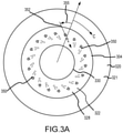
- FIGS. 3A and 3B a frontal view of a guide plate 304 disposed adjacent a forward swirler body face 320 of a retainer body 321 and having a guide plate opening 330, similar to the forward swirler body face 220 of the retainer body 221 and the guide plate opening 230 described above with reference to FIGS. 2A and 2B , is illustrated.
- compressed air from a core flow path C is introduced into a swirler body via one or more pluralities of swirler inlets (e.g., the plurality of primary swirler inlets 212 and the plurality of secondary swirler inlets 213).
- Compressed air from the core flow path C is also introduced into the swirler body via a plurality of purge holes 350 that extend from a forward surface 328 of the guide plate 304 to an aft surface 322 of the guide plate 304.
- each of the plurality of purge holes 350 is oriented at a vector direction 352 that, in various embodiments, is defined by an angle 355 (or a radial angle) with respect to a radial direction R as well as an angle with respect to an axial direction (e.g., the angle 254 with respect to the axial direction A as illustrated in FIGS. 2A and 2B ).
- the orientation of the vector direction 352 produces a vectored purge flow (e.g., the vectored purge flow 256) that exits each of the plurality of purge holes 350 at the aft surface 322 of the guide plate 304 and mixes with a primary swirler flow exiting a plurality of primary swirler inlets (e.g., the primary swirler flow 258 exiting the plurality of primary swirler inlets 212).
- a vectored purge flow e.g., the vectored purge flow 256
- the vector direction 352 includes a component in the axial direction plus a component in the circumferential direction C.
- the component in the circumferential direction C may be in the same direction as a primary swirling flow exiting the plurality of primary swirler inlets, or, in various embodiments, the component in the circumferential direction C may be in the opposite direction as the primary swirling flow exiting the plurality of primary swirler inlets.
- the two situations are illustrated in FIGS. 3A and 3B . As illustrated in FIG.
- the component in the circumferential direction C e.g., the angle 355
- the component in the circumferential direction C of the vectored purge flow exiting the plurality of purge holes 350 is in the positive circumferential direction C
- the component in the circumferential direction C of the vectored purge flow exiting a plurality of purge holes 351 is in the negative circumferential direction C.
- the angle 355 ranges from between about zero degrees (0°) to about sixty degrees (60°); or, in various embodiments, the angle 355 ranges from between about fifteen degrees (15°) to about forty-five degrees (45°); or, in various embodiments, the angle 355 is about thirty degrees (30°). Note that in FIG. 3B , the above stated angles will be in the negative direction, and in both FIGS. 3A and 3B , the zero degree (0°) case defaults to the embodiments illustrated in FIGS. 2A and 2B .
- FIG. 4 a frontal view of a guide plate 404 disposed adjacent a forward swirler body face 420 of a retainer body 421 and having a guide plate opening 430, similar to the forward swirler body face 220 of the retainer body 221 and the guide plate opening 230 described above with reference to FIGS. 2A and 2B , is illustrated.
- compressed air from a core flow path C is introduced into a swirler body via one or more pluralities of swirler inlets (e.g., the plurality of primary swirler inlets 212 and the plurality of secondary swirler inlets 213).
- Compressed air from the core flow path C is also introduced into the swirler body via a first plurality of purge holes 450, producing a first vectored purge flow, and a second plurality of purge holes 451, producing a second vectored purge flow, that extend from a forward surface 428 of the guide plate 404 to an aft surface 422 of the guide plate 404.
- each of the first plurality of purge holes 450 and the second plurality of purge holes 451 is oriented at a vector direction 452 that, in various embodiments, is similar to the vector direction 252 described above with reference to FIGS. 2A and 2B , or the vector direction 352 described above with reference to FIGS. 3A and 3B .
- the vector directions of the first plurality of purge holes 450 and the second plurality of purge holes 451 may be defined by a first axial angle and a first radial angle and a second axial angle and a second radial angle, respectively.
- each of the second plurality of purge holes 451 is oriented in the axial direction, though other directions are contemplated, generally within the ranges described above with reference to FIGS. 2A and 2B and FIGS. 3A and 3B .
- the radial position of each of a plurality of entrance openings 460 (or a first radial entrance position of a first entrance opening) of the first plurality of purge holes 450 is equal to the radial position of each of a plurality of entrance openings 461 (or a second radial entrance position of a second entrance opening) of each of the second plurality of purge holes 451, while in various embodiments, the radial position of each of a plurality of exit openings 462 (or a first radial exit position of a first exit opening) of the first plurality of purge holes 450 is positioned radially inward of the radial position of each of a plurality of exit openings 463 (or a second radial exit position of a
- FIG. 4 illustrates the radial position of each of the plurality of entrance openings 460 of the first plurality of purge holes 450 is equal to the radial position of each of the plurality of entrance openings 461 of each of the second plurality of purge holes 451, the disclosure contemplates other orientations, both for the entrance openings and the exit openings.
- the radial position of each of a plurality of entrance openings 461a of each of the second plurality of purge holes 451 may be positioned at a radial location equal to the radial position of each of the plurality of exit openings 462 of the first plurality of purge holes 450.
- the radial position of each of a plurality of entrance openings 461b of each of the second plurality of purge holes 451 may be positioned at a radial location intermediate the radial position of each of the plurality of exit openings 462 of the first plurality of purge holes 450 and the radial position of each of the plurality of entrance openings 460 of the first plurality of purge holes 450.
- Other such radial positionings of the entrance openings and the exit openings are contemplated by the disclosure.
- FIG. 5 a frontal view of a guide plate 504 disposed adjacent a forward swirler body face 520 of a retainer body 521 and having a guide plate opening 530, similar to the forward swirler body face 220 of the retainer body 221 and the guide plate opening 230 described above with reference to FIGS. 2A and 2B , is illustrated.
- compressed air from a core flow path C is introduced into a swirler body via one or more pluralities of swirler inlets (e.g., the plurality of primary swirler inlets 212 and the plurality of secondary swirler inlets 213).
- Compressed air from the core flow path C is also introduced into the swirler body via a first plurality of purge holes 550, producing a first vectored purge flow, and a second plurality of purge holes 551, producing a second vectored purge flow, that extend from a forward surface 528 of the guide plate 504 to an aft surface 522 of the guide plate 504.
- each of the first plurality of purge holes 550 is oriented at a first vector direction 552 and the second plurality of purge holes 551 is oriented at a second vector direction 553 that, in various embodiments, are similar to the vector direction 252 described above with reference to FIGS. 2A and 2B , or the vector direction 352 described above with reference to FIGS. 3A and 3B .
- the vector directions of the first plurality of purge holes 550 and the second plurality of purge holes 551 may be defined by a first axial angle and a first radial angle and a second axial angle and a second radial angle, respectively.
- the radial position of each of a plurality of entrance openings 560 (or a first radial entrance position of a first entrance opening) of the first plurality of purge holes 550 is radially outward of the radial position of each of a plurality of entrance openings 561 (or a second radial entrance position of a second entrance opening) of each of the second plurality of purge holes 551, while in various embodiments, the radial position of each of a plurality of exit openings 562 (or a first radial exit position of a first exit opening) of the first plurality of purge holes 550 is positioned at a radial position radially outward of each of a plurality of exit openings 563 (or a second radial exit position of a second exit opening) of each of the second plurality of purge holes 551.
- the concepts and applications described improve flow instabilities within and downstream of a swirler body by adding an auxiliary flow of air through a guide plate.
- the auxiliary flow of air reduces the flow instabilities that are known drivers of tones or pressure oscillations in the combustor.
- the auxiliary flow of air also reduces the otherwise large regions of low pressure recirculation at the center of the swirler along the fuel nozzle tip.
- the guide plates described above direct air around the fuel nozzle to force the recirculation away from the fuel nozzle tip, which reduces perturbations in the reacting flow downstream of the swirler.
- the guide plate design may be implemented and tailored to a variety of different 2-Pass and 3-Pass swirler configurations to reduce tones or pressure oscillations in a combustor.
- references to "one embodiment,” “an embodiment,” “various embodiments,” etc. indicate that the embodiment described may include a particular feature, structure, or characteristic, but every embodiment may not necessarily include the particular feature, structure, or characteristic. Moreover, such phrases are not necessarily referring to the same embodiment. Further, when a particular feature, structure, or characteristic is described in connection with an embodiment, it is submitted that it is within the knowledge of one skilled in the art to affect such feature, structure, or characteristic in connection with other embodiments whether or not explicitly described. After reading the description, it will be apparent to one skilled in the relevant art(s) how to implement the disclosure in alternative embodiments.
- Numbers, percentages, or other values stated herein are intended to include that value, and also other values that are about or approximately equal to the stated value, as would be appreciated by one of ordinary skill in the art encompassed by various embodiments of the present disclosure.
- a stated value should therefore be interpreted broadly enough to encompass values that are at least close enough to the stated value to perform a desired function or achieve a desired result.
- the stated values include at least the variation to be expected in a suitable industrial process, and may include values that are within 10%, within 5%, within 1%, within 0.1%, or within 0.01% of a stated value.
- the terms “substantially,” “about” or “approximately” as used herein represent an amount close to the stated amount that still performs a desired function or achieves a desired result.
- the term “substantially,” “about” or “approximately” may refer to an amount that is within 10% of, within 5% of, within 1% of, within 0.1% of, and within 0.01% of a stated amount or value
Abstract
Description
- The present disclosure relates generally to gas turbine engines and, more particularly, to fuel swirlers used in combustor sections of gas turbine engines.
- Gas turbine engines typically include a fan section, a compressor section, a combustor section and a turbine section. The fan section drives air along a bypass flow path while the compressor section drives air along a core flow path. In general, during operation, air is pressurized in the compressor section and is mixed with fuel and burned in the combustor section to generate hot combustion gases. Efficient and thorough mixing and combustion of the fuel and air is often facilitated using swirlers disposed upstream of a combustion zone where burning of the fuel and air occurs. Following combustion, the hot combustion gases flow through the turbine section, which extracts energy from the hot combustion gases to power the compressor section and other gas turbine engine loads, such as those required to rotate fan blades in the fan section. The compressor section typically includes a low pressure compressor and a high pressure compressor, and the turbine section typically includes a low pressure turbine and a high pressure turbine connected, respectively, to the low pressure compressor and to the high pressure compressor.
- A guide plate for a swirler assembly is disclosed. In various embodiments, the guide plate includes a guide plate flange configured for engagement with a swirler body having a plurality of primary swirler inlets; and a first plurality of purge holes extending through the guide plate flange and configured to introduce a first vectored purge flow into the swirler body.
- In various embodiments, each of the first plurality of purge holes is defined by a first axial angle with respect to a longitudinal axis extending through the swirler body. In various embodiments, the first axial angle is from about zero degrees to about sixty degrees. In various embodiments, each of the first plurality of purge holes is defined by a first radial angle with respect to a radial axis extending through the swirler body. In various embodiments, the first radial angle is from about zero degrees to about sixty degrees. In various embodiments, a second plurality of purge holes extends through the guide plate flange and is configured to introduce a second vectored purge flow into the swirler body.
- In various embodiments, each of the first plurality of purge holes has a first entrance opening positioned at a first radial entrance position and each of the second plurality of purge holes has a second entrance opening positioned at a second radial entrance position, the second radial entrance position being different from the first radial entrance position. In various embodiments, each of the first plurality of purge holes has a first exit opening positioned at a first radial exit position and each of the second plurality of purge holes has a second exit opening positioned at a second radial exit position, the second radial exit position being equal to the first radial exit position.
- In various embodiments, each of the first plurality of purge holes has a first exit opening positioned at a first radial exit position and each of the second plurality of purge holes has a second exit opening positioned at a second radial exit position, the second radial exit position being different from the first radial exit position.
- In various embodiments, each of the first plurality of purge holes is defined by a first axial angle with respect to a longitudinal axis extending through the swirler body and each of the second plurality of purge holes is defined by a second axial angle with respect to the longitudinal axis, the second axial angle being different from the first axial angle.
- In various embodiments, each of the first plurality of purge holes is defined by a first radial angle with respect to a radial axis extending through the swirler body and each of the second plurality of purge holes is defined by a second radial angle with respect to the radial axis, the second radial angle being different from the first radial angle.
- A swirler assembly is disclosed. In various embodiments, the swirler assembly includes a swirler body defining an axial direction and having a plurality of primary swirler inlets extending through the swirler body to a radially inner swirler surface of the swirler body; and a guide plate configured for engagement with the swirler body, the guide plate including a first plurality of purge holes extending through a guide plate flange and configured to introduce a first vectored purge flow into the swirler body.
- In various embodiments, each of the first plurality of purge holes is defined by a first axial angle with respect to a longitudinal axis extending through the swirler body, the first axial angle being from about zero degrees to about sixty degrees. In various embodiments, each of the first plurality of purge holes is defined by a first radial angle with respect to a radial axis extending through the swirler body, the first radial angle being from about zero degrees to about sixty degrees. In various embodiments, a second plurality of purge holes extends through the guide plate flange and is configured to introduce a second vectored purge flow into the swirler body.
- In various embodiments, each of the first plurality of purge holes has a first entrance opening positioned at a first radial entrance position and each of the second plurality of purge holes has a second entrance opening positioned at a second radial entrance position, the second radial entrance position being equal to the first radial entrance position.
- In various embodiments, each of the first plurality of purge holes has a first exit opening positioned at a first radial exit position and each of the second plurality of purge holes has a second exit opening positioned at a second radial exit position, the second radial exit position being equal to the first radial exit position.
- In various embodiments, each of the first plurality of purge holes has a first exit opening positioned at a first radial exit position and each of the second plurality of purge holes has a second exit opening positioned at a second radial exit position, the second radial exit position being different from the first radial exit position.
- In various embodiments, each of the first plurality of purge holes is defined by a first axial angle with respect to a longitudinal axis extending through the swirler body and each of the second plurality of purge holes is defined by a second axial angle with respect to the longitudinal axis, the second axial angle being different from the first axial angle.
- In various embodiments, each of the first plurality of purge holes is defined by a first radial angle with respect to a radial axis extending through the swirler body and each of the second plurality of purge holes is defined by a second radial angle with respect to the radial axis, the second radial angle being different from the first radial angle.
- The foregoing features and elements may be combined in various combinations, without exclusivity, unless expressly indicated herein otherwise. These features and elements as well as the operation of the disclosed embodiments will become more apparent in light of the following description and accompanying drawings.
- The subject matter of the present disclosure is particularly pointed out and distinctly claimed in the concluding portion of the specification. A more complete understanding of the present disclosure, however, may best be obtained by referring to the following detailed description and claims in connection with the following drawings. While the drawings illustrate various embodiments employing the principles described herein, the drawings do not limit the scope of the claims.
-
FIG. 1A is a cross sectional schematic view of a gas turbine engine, in accordance with various embodiments; -
FIG. 1B is a cross sectional schematic view of a combustor section of a gas turbine engine, in accordance with various embodiments; -
FIG. 2A is a cross sectional view of a swirler assembly, in accordance with various embodiments; -
FIG. 2B is a frontal view of a guide plate, in accordance with various embodiments; -
FIGS. 3A and3B are frontal views of guide plates, in accordance with various embodiments; -
FIG. 4 is a frontal view of a guide plate, in accordance with various embodiments; and -
FIG. 5 is a frontal view of a guide plate, in accordance with various embodiments. - The following detailed description of various embodiments herein makes reference to the accompanying drawings, which show various embodiments by way of illustration. While these various embodiments are described in sufficient detail to enable those skilled in the art to practice the disclosure, it should be understood that other embodiments may be realized and that changes may be made without departing from the scope of the disclosure. Thus, the detailed description herein is presented for purposes of illustration only and not of limitation. Furthermore, any reference to singular includes plural embodiments, and any reference to more than one component or step may include a singular embodiment or step. Also, any reference to attached, fixed, connected, or the like may include permanent, removable, temporary, partial, full or any other possible attachment option. Additionally, any reference to without contact (or similar phrases) may also include reduced contact or minimal contact. It should also be understood that unless specifically stated otherwise, references to "a," "an" or "the" may include one or more than one and that reference to an item in the singular may also include the item in the plural. Further, all ranges may include upper and lower values and all ranges and ratio limits disclosed herein may be combined.
- Referring now to the drawings,
FIG. 1A schematically illustrates agas turbine engine 20. Thegas turbine engine 20 is disclosed herein as a two-spool turbofan that generally incorporates afan section 22, acompressor section 24, acombustor section 26 and aturbine section 28. Thefan section 22 drives air along a bypass flow path B in a bypass duct defined within anacelle 15, while thecompressor section 24 drives air along a core flow path C for compression and communication into thecombustor section 26 and then expansion through theturbine section 28. Although depicted as a two-spool turbofan gas turbine engine in the disclosed non-limiting embodiment, the concepts described herein are not limited to use with two-spool turbofans as the teachings may be applied to other types of turbine engines. - The
gas turbine engine 20 generally includes alow speed spool 30 and ahigh speed spool 32 mounted for rotation about an engine central longitudinal axis A relative to an enginestatic structure 36 viaseveral bearing systems 38. Various bearing systems at various locations may alternatively or additionally be provided and the location of theseveral bearing systems 38 may be varied as appropriate to the application. Thelow speed spool 30 generally includes aninner shaft 40 that interconnects afan 42, alow pressure compressor 44 and alow pressure turbine 46. Theinner shaft 40 is connected to thefan 42 through a speed change mechanism, which in thisgas turbine engine 20 is illustrated as a fandrive gear system 48 configured to drive thefan 42 at a lower speed than that of thelow speed spool 30. Thehigh speed spool 32 includes anouter shaft 50 that interconnects ahigh pressure compressor 52 and ahigh pressure turbine 54. Acombustor 56 is arranged in thegas turbine engine 20 between thehigh pressure compressor 52 and thehigh pressure turbine 54. Amid-turbine frame 57 of the enginestatic structure 36 is arranged generally between thehigh pressure turbine 54 and thelow pressure turbine 46 and may includeairfoils 59 in the core flow path C for guiding the flow into thelow pressure turbine 46. Themid-turbine frame 57 further supports theseveral bearing systems 38 in theturbine section 28. Theinner shaft 40 and theouter shaft 50 are concentric and rotate via theseveral bearing systems 38 about the engine central longitudinal axis A, which is collinear with longitudinal axes of theinner shaft 40 and theouter shaft 50. - The air in the core flow path C is compressed by the
low pressure compressor 44 and then thehigh pressure compressor 52, mixed and burned with fuel in thecombustor 56, and then expanded over thehigh pressure turbine 54 and thelow pressure turbine 46. Thelow pressure turbine 46 and thehigh pressure turbine 54 rotationally drive the respectivelow speed spool 30 and thehigh speed spool 32 in response to the expansion. It will be appreciated that each of the positions of thefan section 22, thecompressor section 24, thecombustor section 26, theturbine section 28, and the fandrive gear system 48 may be varied. For example, the fandrive gear system 48 may be located aft of thecombustor section 26 or even aft of theturbine section 28, and thefan section 22 may be positioned forward or aft of the location of the fandrive gear system 48. - Referring to
FIG. 1B , thecombustor 56 may generally include anouter liner assembly 60, aninner liner assembly 62 and adiffuser case module 64 that surrounds theouter liner assembly 60 and theinner liner assembly 62. Acombustion chamber 66, positioned within thecombustor 56, has a generally annular configuration, defined by and comprising theouter liner assembly 60, theinner liner assembly 62 and abulkhead liner assembly 88. Theouter liner assembly 60 and theinner liner assembly 62 are generally cylindrical and radially spaced apart, with thebulkhead liner assembly 88 positioned generally at a forward end of thecombustion chamber 66. Theouter liner assembly 60 is spaced radially inward from anouter diffuser case 68 of thediffuser case module 64 to define an outerannular plenum 70. Theinner liner assembly 62 is spaced radially outward from aninner diffuser case 72 of thediffuser case module 64 to define, in-part, an innerannular plenum 74. Although a particular combustor is illustrated, it should be understood that other combustor types with various combustor liner arrangements will also benefit from this disclosure. It should be further understood that the disclosed cooling flow paths are but an illustrated embodiment. - The
combustion chamber 66 contains the combustion products that flow axially toward theturbine section 28. Theouter liner assembly 60 includes anouter support shell 76 and theinner liner assembly 62 includes aninner support shell 78. Theouter support shell 76 supports one or moreouter panels 80 and theinner support shell 78 supports one or moreinner panels 82. Each of theouter panels 80 and theinner panels 82 may be formed of a plurality of floating panels that are generally rectilinear and manufactured from, for example, a nickel based super alloy that may be coated with a ceramic or other temperature resistant material, and are arranged to form a panel configuration mounted to the respectiveouter support shell 76 andinner support shell 78. In various embodiments, the combination of theouter support shell 76 and theouter panels 80 is referred to an outer heat shield or outer heat shield liner, while the combination of theinner support shell 78 and theinner panels 82 is referred to as an inner heat shield or inner heat shield liner. In various embodiments, the panels are secured to the shells via one ormore attachment mechanisms 75, which may each comprise a threaded stud and nut assembly. - The
combustor 56 further includes aforward assembly 84 that receives compressed airflow from thecompressor section 24 located immediately upstream. Theforward assembly 84 generally includes anannular hood 86, abulkhead liner assembly 88, and a plurality of swirler assemblies 90 (one shown). Each of the plurality ofswirler assemblies 90 is aligned with a respective one of a plurality of fuel nozzles 92 (one shown) and a respective one of a plurality of hood ports 94 (one shown) to project through thebulkhead liner assembly 88; generally, the plurality ofswirler assemblies 90, the plurality offuel nozzles 92 and the plurality ofhood ports 94 are circumferentially distributed about theannular hood 86 and thebulkhead liner assembly 88. Thebulkhead liner assembly 88 includes abulkhead support shell 96 secured to theouter liner assembly 60 and to theinner liner assembly 62 and a plurality ofbulkhead panels 98 secured to thebulkhead support shell 96; generally, the plurality ofbulkhead panels 98 is circumferentially distributed about thebulkhead liner assembly 88. Thebulkhead support shell 96 is generally annular and the plurality ofbulkhead panels 98 is segmented, typically one panel to each of the plurality offuel nozzles 92 and the plurality ofswirler assemblies 90. Theannular hood 86 extends radially between, and is secured to, the forward-most ends of theouter liner assembly 60 and theinner liner assembly 62. Each of the plurality ofhood ports 94 receives a respective one of the plurality offuel nozzles 92 and facilitates the direction of compressed air into the forward end of thecombustion chamber 66 through a respective one of a plurality ofswirler openings 100. Each of the plurality offuel nozzles 92 may be secured to thediffuser case module 64 and project through a respective one of the plurality ofhood ports 94 and into a respective one of the plurality ofswirler assemblies 90. - The
forward assembly 84 introduces compressed air from the core flow path C into the forward section of thecombustion chamber 66 while the remainder of the compressed air enters the outerannular plenum 70 and the innerannular plenum 74. The plurality offuel nozzles 92 and adjacent structure generate a blended fuel-air mixture that supports stable combustion in thecombustion chamber 66. An igniter 79 is located downstream of the plurality offuel nozzles 92 used to ignite the blended fuel-air mixture. Air in the outerannular plenum 70 and the innerannular plenum 74 is also introduced into thecombustion chamber 66 via a plurality oforifices 77, which may include dilution holes or air feed holes of various dimension. Theouter support shell 76 may also include a plurality of impingement holes that introduce cooling air from the outerannular plenum 70 into a space between theouter support shell 76 and a cool side of theouter panels 80. The cooling air is then communicated through a plurality of effusion holes in theouter panels 80 to form a cooling air film across a hot side of theouter panels 80 to thermally protect theouter panels 80 from hot combustion gases. Similarly, theinner support shell 78 may include a plurality of impingement holes that introduce cooling air from the innerannular plenum 74 into a space between theinner support shell 78 and a cool side of theinner panels 82. The cooling air is then communicated through a plurality of effusion holes in theinner panels 82 to form a cooling air film across a hot side of theinner panels 82 to thermally protect theinner panels 82 from hot combustion gases. - Referring now to
FIGS. 2A and 2B , aswirler assembly 200, such as, for example, one of the plurality ofswirler assemblies 90 described above with reference toFIG. 1B , is illustrated with reference to an axial direction A (or a longitudinal axis) and a radial direction R (or a radial axis). Theswirler assembly 200 may comprise aswirler body 202, aguide plate 204 and a retainingring 206. In various embodiments, theswirler body 202 is configured to swirl airflow and provide the swirled airflow into a combustion chamber, such as, for example, thecombustion chamber 66 described above with reference toFIG. 1B . Theswirler body 202 may comprise a radiallyouter swirler surface 208 and a radiallyinner swirler surface 210. Theswirler body 202 typically includes a plurality ofprimary swirler inlets 212 spaced circumferentially about the radiallyouter swirler surface 208. Each of the plurality ofprimary swirler inlets 212 defines a radial void extending through the radiallyouter swirler surface 208 that is configured to receive a flow of compressed air from a core flow path C (e.g., from thecompressor section 24 described above with reference toFIGS. 1A and1B ), impart a swirl to the flow, and then introduce the swirling flow through theswirler body 202, via aswirler opening 214 extending along an axial length of theswirler body 202, and into the combustion chamber. Theswirler body 202 may comprise a forwardswirler body portion 216 located axially opposite an aftswirler body portion 218, between which theswirler opening 214 extends. In various embodiments, theswirler body 202 may further comprise a plurality ofsecondary swirler inlets 213 disposed downstream of the plurality ofprimary swirler inlets 212 and configured to introduce a secondary swirling flow downstream of the aftswirler body portion 218. - In various embodiments, the forward
swirler body portion 216 is configured to interface with theguide plate 204. For example, theswirler body 202 may comprise a forwardswirler body face 220 that is positioned axially inward of the forwardswirler body portion 216. The axially inward position provides for aswirler body recession 217 that extends circumferentially around the forwardswirler body face 220 and is configured to at least partially receive anaft surface 222 of aguide plate flange 224. In this manner, the forwardswirler body face 220 may comprise any suitable size capable of at least partially receiving theguide plate flange 224 within theswirler body recession 217. For example, the forwardswirler body face 220 may comprise an inner diameter (in the radial direction) greater than an outer diameter ofguide plate flange 224, such that theguide plate 204 may fit within theswirler body recession 217. The forwardswirler body portion 216 may also define anannular wall portion 226 that circumferentially surrounds the forwardswirler body face 220 and is sized to receive theguide plate flange 224. In various embodiments, the forwardswirler body face 220 is considered part of aretainer body 221 that is configured to receive and retain, in conjunction with the retainingring 206, theguide plate flange 224 within theswirler body recession 217. - In various embodiments, the
guide plate 204 may be configured to at least partially provide sealing between the higher pressure upstream air located radially outward from theswirler body 202 and the lower pressure downstream air located withinswirler body 202. In this regard, theguide plate 204 may provide sealing to ensure the compressed air from the compressor section is forced into the plurality ofprimary swirler inlets 212 extending in to theswirler body 202. In various embodiments, theguide plate 204 may comprise aforward surface 228 axially opposite theaft surface 222 of theguide plate flange 224. Theaft surface 222 may be configured to couple to or interface with the forward swirler body face 220 of theretainer body 221, allowing theguide plate 204 to at least partially fit within swirler body 202 (or at least partially fit within the swirler body recession 217). Theguide plate 204 may also comprise a guide plate opening 230 configured to receive a nozzle end of afuel nozzle 219, such as, for example, one of the plurality offuel nozzles 92 described above with reference toFIG. 1B . In various embodiments, theguide plate opening 230 defines an axial void that substantially aligns with theswirler opening 214 when theguide plate 204 is assembled with theswirler body 202 and thefuel nozzle 219. - In various embodiments, the
guide plate 204 may comprise aguide plate collar 232 having aforward protrusion 234 and anaft protrusion 236. In various embodiments, theforward protrusion 234 is located on theforward surface 228 and extends in an axial direction away from theforward surface 228 of theguide plate 204. In various embodiments, theforward protrusion 234 may define a forward circumferential boundary for theguide plate opening 230. Similarly, theaft protrusion 236 is located on theaft surface 222 and extends in an axial direction away from theaft surface 222 of theguide plate 204. Theaft protrusion 236 may define an aft circumferential boundary for theguide plate opening 230. In various embodiments, the forward circumferential boundary and the aft circumferential boundary are configured to receive thefuel nozzle 219 when assembled into the combustor. In various embodiments, the retainingring 206 is configured to retain theguide plate flange 224 within theswirler body recession 217. - Referring more particularly to
FIG. 2B , with continued reference toFIG. 2A , further details of theguide plate 204 are discussed. As illustrated, compressed air from the core flow path C is introduced into the interior of theswirler body 202 via the plurality ofprimary swirler inlets 212. Compressed air from the core flow path C is also introduced into the swirler body via a plurality of purge holes 250 that extend from theforward surface 228 of theguide plate 204 to theaft surface 222 of theguide plate 204. As illustrated, each of the plurality of purge holes 250 is oriented at avector direction 252 that, in various embodiments, is defined by an angle 254 (or an axial angle) with respect to the axial direction A. The orientation of thevector direction 252 produces a vectoredpurge flow 256 that exits each of the plurality of purge holes 250 at theaft surface 222 of theguide plate 204 and mixes with aprimary swirler flow 258 exiting the plurality ofprimary swirler inlets 212. In various embodiments, theangle 254 ranges from between about zero degrees (0°) to about sixty degrees (60°); or, in various embodiments, theangle 254 ranges from between about fifteen degrees (15°) to about forty-five degrees (45°); or, in various embodiments, theangle 254 is about thirty degrees (30°). - Referring now to
FIGS. 3A and3B , a frontal view of aguide plate 304 disposed adjacent a forward swirler body face 320 of aretainer body 321 and having aguide plate opening 330, similar to the forward swirler body face 220 of theretainer body 221 and the guide plate opening 230 described above with reference toFIGS. 2A and 2B , is illustrated. In a manner similar to theswirler assembly 200 described above, compressed air from a core flow path C is introduced into a swirler body via one or more pluralities of swirler inlets (e.g., the plurality ofprimary swirler inlets 212 and the plurality of secondary swirler inlets 213). Compressed air from the core flow path C is also introduced into the swirler body via a plurality of purge holes 350 that extend from aforward surface 328 of theguide plate 304 to anaft surface 322 of theguide plate 304. As illustrated, each of the plurality of purge holes 350 is oriented at avector direction 352 that, in various embodiments, is defined by an angle 355 (or a radial angle) with respect to a radial direction R as well as an angle with respect to an axial direction (e.g., theangle 254 with respect to the axial direction A as illustrated inFIGS. 2A and 2B ). The orientation of thevector direction 352 produces a vectored purge flow (e.g., the vectored purge flow 256) that exits each of the plurality of purge holes 350 at theaft surface 322 of theguide plate 304 and mixes with a primary swirler flow exiting a plurality of primary swirler inlets (e.g., theprimary swirler flow 258 exiting the plurality of primary swirler inlets 212). - A difference between the embodiments illustrated in
FIGS. 2A and 2B andFIGS. 3A and3B is the latter embodiments introduce a swirl component to the vector directions of the plurality of purge holes 350. More specifically, thevector direction 352 includes a component in the axial direction plus a component in the circumferential direction C. In various embodiments, the component in the circumferential direction C may be in the same direction as a primary swirling flow exiting the plurality of primary swirler inlets, or, in various embodiments, the component in the circumferential direction C may be in the opposite direction as the primary swirling flow exiting the plurality of primary swirler inlets. The two situations are illustrated inFIGS. 3A and3B . As illustrated inFIG. 3A , for example, the component in the circumferential direction C (e.g., the angle 355) of the vectored purge flow exiting the plurality of purge holes 350 is in the positive circumferential direction C, whereas inFIG. 3B , the component in the circumferential direction C of the vectored purge flow exiting a plurality of purge holes 351 is in the negative circumferential direction C. In various embodiments, theangle 355 ranges from between about zero degrees (0°) to about sixty degrees (60°); or, in various embodiments, theangle 355 ranges from between about fifteen degrees (15°) to about forty-five degrees (45°); or, in various embodiments, theangle 355 is about thirty degrees (30°). Note that inFIG. 3B , the above stated angles will be in the negative direction, and in bothFIGS. 3A and3B , the zero degree (0°) case defaults to the embodiments illustrated inFIGS. 2A and 2B . - Referring now to
FIG. 4 , a frontal view of aguide plate 404 disposed adjacent a forward swirler body face 420 of aretainer body 421 and having aguide plate opening 430, similar to the forward swirler body face 220 of theretainer body 221 and the guide plate opening 230 described above with reference toFIGS. 2A and 2B , is illustrated. In a manner similar to theswirler assembly 200 described above, compressed air from a core flow path C is introduced into a swirler body via one or more pluralities of swirler inlets (e.g., the plurality ofprimary swirler inlets 212 and the plurality of secondary swirler inlets 213). Compressed air from the core flow path C is also introduced into the swirler body via a first plurality of purge holes 450, producing a first vectored purge flow, and a second plurality of purge holes 451, producing a second vectored purge flow, that extend from aforward surface 428 of theguide plate 404 to anaft surface 422 of theguide plate 404. - As illustrated, each of the first plurality of purge holes 450 and the second plurality of purge holes 451 is oriented at a
vector direction 452 that, in various embodiments, is similar to thevector direction 252 described above with reference toFIGS. 2A and 2B , or thevector direction 352 described above with reference toFIGS. 3A and3B . In other words, the vector directions of the first plurality of purge holes 450 and the second plurality of purge holes 451 may be defined by a first axial angle and a first radial angle and a second axial angle and a second radial angle, respectively. As illustrated, each of the second plurality of purge holes 451 is oriented in the axial direction, though other directions are contemplated, generally within the ranges described above with reference toFIGS. 2A and 2B andFIGS. 3A and3B . In various embodiments, the radial position of each of a plurality of entrance openings 460 (or a first radial entrance position of a first entrance opening) of the first plurality of purge holes 450 is equal to the radial position of each of a plurality of entrance openings 461 (or a second radial entrance position of a second entrance opening) of each of the second plurality of purge holes 451, while in various embodiments, the radial position of each of a plurality of exit openings 462 (or a first radial exit position of a first exit opening) of the first plurality of purge holes 450 is positioned radially inward of the radial position of each of a plurality of exit openings 463 (or a second radial exit position of a second exit opening) of each of the second plurality of purge holes 451. - Note that while
FIG. 4 illustrates the radial position of each of the plurality ofentrance openings 460 of the first plurality of purge holes 450 is equal to the radial position of each of the plurality ofentrance openings 461 of each of the second plurality of purge holes 451, the disclosure contemplates other orientations, both for the entrance openings and the exit openings. For example, in various embodiments, the radial position of each of a plurality ofentrance openings 461a of each of the second plurality of purge holes 451 may be positioned at a radial location equal to the radial position of each of the plurality ofexit openings 462 of the first plurality of purge holes 450. Or, in various embodiments, the radial position of each of a plurality ofentrance openings 461b of each of the second plurality of purge holes 451 may be positioned at a radial location intermediate the radial position of each of the plurality ofexit openings 462 of the first plurality of purge holes 450 and the radial position of each of the plurality ofentrance openings 460 of the first plurality of purge holes 450. Other such radial positionings of the entrance openings and the exit openings are contemplated by the disclosure. - Referring now to
FIG. 5 , a frontal view of aguide plate 504 disposed adjacent a forward swirler body face 520 of aretainer body 521 and having aguide plate opening 530, similar to the forward swirler body face 220 of theretainer body 221 and the guide plate opening 230 described above with reference toFIGS. 2A and 2B , is illustrated. In a manner similar to theswirler assembly 200 described above, compressed air from a core flow path C is introduced into a swirler body via one or more pluralities of swirler inlets (e.g., the plurality ofprimary swirler inlets 212 and the plurality of secondary swirler inlets 213). Compressed air from the core flow path C is also introduced into the swirler body via a first plurality of purge holes 550, producing a first vectored purge flow, and a second plurality of purge holes 551, producing a second vectored purge flow, that extend from aforward surface 528 of theguide plate 504 to anaft surface 522 of theguide plate 504. - As illustrated, each of the first plurality of purge holes 550 is oriented at a
first vector direction 552 and the second plurality of purge holes 551 is oriented at asecond vector direction 553 that, in various embodiments, are similar to thevector direction 252 described above with reference toFIGS. 2A and 2B , or thevector direction 352 described above with reference toFIGS. 3A and3B . In other words, the vector directions of the first plurality of purge holes 550 and the second plurality of purge holes 551 may be defined by a first axial angle and a first radial angle and a second axial angle and a second radial angle, respectively. In various embodiments, the radial position of each of a plurality of entrance openings 560 (or a first radial entrance position of a first entrance opening) of the first plurality of purge holes 550 is radially outward of the radial position of each of a plurality of entrance openings 561 (or a second radial entrance position of a second entrance opening) of each of the second plurality of purge holes 551, while in various embodiments, the radial position of each of a plurality of exit openings 562 (or a first radial exit position of a first exit opening) of the first plurality of purge holes 550 is positioned at a radial position radially outward of each of a plurality of exit openings 563 (or a second radial exit position of a second exit opening) of each of the second plurality of purge holes 551. - The concepts and applications described improve flow instabilities within and downstream of a swirler body by adding an auxiliary flow of air through a guide plate. The auxiliary flow of air reduces the flow instabilities that are known drivers of tones or pressure oscillations in the combustor. The auxiliary flow of air also reduces the otherwise large regions of low pressure recirculation at the center of the swirler along the fuel nozzle tip. The guide plates described above direct air around the fuel nozzle to force the recirculation away from the fuel nozzle tip, which reduces perturbations in the reacting flow downstream of the swirler. The guide plate design may be implemented and tailored to a variety of different 2-Pass and 3-Pass swirler configurations to reduce tones or pressure oscillations in a combustor.
- Benefits, other advantages, and solutions to problems have been described herein with regard to specific embodiments. Furthermore, the connecting lines shown in the various figures contained herein are intended to represent exemplary functional relationships and/or physical couplings between the various elements. It should be noted that many alternative or additional functional relationships or physical connections may be present in a practical system. However, the benefits, advantages, solutions to problems, and any elements that may cause any benefit, advantage, or solution to occur or become more pronounced are not to be construed as critical, required, or essential features or elements of the disclosure. The scope of the disclosure is accordingly to be limited by nothing other than the appended claims, in which reference to an element in the singular is not intended to mean "one and only one" unless explicitly so stated, but rather "one or more." Moreover, where a phrase similar to "at least one of A, B, or C" is used in the claims, it is intended that the phrase be interpreted to mean that A alone may be present in an embodiment, B alone may be present in an embodiment, C alone may be present in an embodiment, or that any combination of the elements A, B and C may be present in a single embodiment; for example, A and B, A and C, B and C, or A and B and C. Different cross-hatching is used throughout the figures to denote different parts but not necessarily to denote the same or different materials.
- Systems, methods and apparatus are provided herein. In the detailed description herein, references to "one embodiment," "an embodiment," "various embodiments," etc., indicate that the embodiment described may include a particular feature, structure, or characteristic, but every embodiment may not necessarily include the particular feature, structure, or characteristic. Moreover, such phrases are not necessarily referring to the same embodiment. Further, when a particular feature, structure, or characteristic is described in connection with an embodiment, it is submitted that it is within the knowledge of one skilled in the art to affect such feature, structure, or characteristic in connection with other embodiments whether or not explicitly described. After reading the description, it will be apparent to one skilled in the relevant art(s) how to implement the disclosure in alternative embodiments.
- Numbers, percentages, or other values stated herein are intended to include that value, and also other values that are about or approximately equal to the stated value, as would be appreciated by one of ordinary skill in the art encompassed by various embodiments of the present disclosure. A stated value should therefore be interpreted broadly enough to encompass values that are at least close enough to the stated value to perform a desired function or achieve a desired result. The stated values include at least the variation to be expected in a suitable industrial process, and may include values that are within 10%, within 5%, within 1%, within 0.1%, or within 0.01% of a stated value. Additionally, the terms "substantially," "about" or "approximately" as used herein represent an amount close to the stated amount that still performs a desired function or achieves a desired result. For example, the term "substantially," "about" or "approximately" may refer to an amount that is within 10% of, within 5% of, within 1% of, within 0.1% of, and within 0.01% of a stated amount or value.
- Furthermore, no element, component, or method step in the present disclosure is intended to be dedicated to the public regardless of whether the element, component, or method step is explicitly recited in the claims. No claim element herein is to be construed under the provisions of 35 U.S.C. 112(f) unless the element is expressly recited using the phrase "means for." As used herein, the terms "comprises," "comprising," or any other variation thereof, are intended to cover a non-exclusive inclusion, such that a process, method, article, or apparatus that comprises a list of elements does not include only those elements but may include other elements not expressly listed or inherent to such process, method, article, or apparatus.
- Finally, it should be understood that any of the above described concepts can be used alone or in combination with any or all of the other above described concepts. Although various embodiments have been disclosed and described, one of ordinary skill in this art would recognize that certain modifications would come within the scope of this disclosure. Accordingly, the description is not intended to be exhaustive or to limit the principles described or illustrated herein to any precise form. Many modifications and variations are possible in light of the above teaching.
Claims (15)
- A guide plate for a swirler assembly, comprising:a guide plate flange configured for engagement with a swirler body having a plurality of primary swirler inlets; anda first plurality of purge holes extending through the guide plate flange and configured to introduce a first vectored purge flow into the swirler body.
- The guide plate of claim 1, wherein each of the first plurality of purge holes is defined by a first axial angle with respect to a longitudinal axis extending through the swirler body.
- The guide plate of claim 2, wherein the first axial angle is from about zero degrees to about sixty degrees.
- The guide plate of any preceding claim, wherein each of the first plurality of purge holes is defined by a first radial angle with respect to a radial axis extending through the swirler body.
- The guide plate of claim 4, wherein the first radial angle is from about zero degrees to about sixty degrees.
- The guide plate of any preceding claim, further comprising a second plurality of purge holes extending through the guide plate flange and configured to introduce a second vectored purge flow into the swirler body.
- The guide plate of claim 6, wherein each of the first plurality of purge holes has a first entrance opening positioned at a first radial entrance position and each of the second plurality of purge holes has a second entrance opening positioned at a second radial entrance position, the second radial entrance position being different from the first radial entrance position.
- A swirler assembly, comprising:a swirler body defining an axial direction and having a plurality of primary swirler inlets extending through the swirler body to a radially inner swirler surface of the swirler body; anda guide plate configured for engagement with the swirler body, the guide plate including a first plurality of purge holes extending through a guide plate flange and configured to introduce a first vectored purge flow into the swirler body.
- The swirler assembly of claim 8, wherein each of the first plurality of purge holes is defined by a first axial angle with respect to a longitudinal axis extending through the swirler body, the first axial angle being from about zero degrees to about sixty degrees.
- The swirler assembly of claim 8 or 9, wherein each of the first plurality of purge holes is defined by a first radial angle with respect to a radial axis extending through the swirler body, the first radial angle being from about zero degrees to about sixty degrees.
- The swirler assembly of claim 8, 9 or 10, further comprising a second plurality of purge holes extending through the guide plate flange and configured to introduce a second vectored purge flow into the swirler body.
- The guide plate of claim 6 or the swirler assembly of claim 11, wherein each of the first plurality of purge holes has a first entrance opening positioned at a first radial entrance position and each of the second plurality of purge holes has a second entrance opening positioned at a second radial entrance position, the second radial entrance position being equal to the first radial entrance position.
- The guide plate of claim 6, 7 or 12 or the swirler assembly of claim 11 or 12, wherein each of the first plurality of purge holes has a first exit opening positioned at a first radial exit position and each of the second plurality of purge holes has a second exit opening positioned at a second radial exit position, the second radial exit position being equal to the first radial exit position, or,
wherein each of the first plurality of purge holes has a first exit opening positioned at a first radial exit position and each of the second plurality of purge holes has a second exit opening positioned at a second radial exit position, the second radial exit position being different from the first radial exit position. - The guide plate of claim 6, 7, 12 or 13 or the swirler assembly of claim 11, 12 or 13, wherein each of the first plurality of purge holes is defined by a first axial angle with respect to a longitudinal axis extending through the swirler body and each of the second plurality of purge holes is defined by a second axial angle with respect to the longitudinal axis, the second axial angle being different from the first axial angle.
- The guide plate of claim 6 or 7 or any of claims 12 to 14 or the swirler assembly of any of claims 11 to 14, wherein each of the first plurality of purge holes is defined by a first radial angle with respect to a radial axis extending through the swirler body and each of the second plurality of purge holes is defined by a second radial angle with respect to the radial axis, the second radial angle being different from the first radial angle.
Applications Claiming Priority (1)
| Application Number | Priority Date | Filing Date | Title |
|---|---|---|---|
| US17/021,199 US20220082258A1 (en) | 2020-09-15 | 2020-09-15 | Fuel nozzle air swirler |
Publications (1)
| Publication Number | Publication Date |
|---|---|
| EP3967929A1 true EP3967929A1 (en) | 2022-03-16 |
Family
ID=77774833
Family Applications (1)
| Application Number | Title | Priority Date | Filing Date |
|---|---|---|---|
| EP21196928.2A Pending EP3967929A1 (en) | 2020-09-15 | 2021-09-15 | Fuel nozzle air swirler |
Country Status (2)
| Country | Link |
|---|---|
| US (1) | US20220082258A1 (en) |
| EP (1) | EP3967929A1 (en) |
Citations (5)
| Publication number | Priority date | Publication date | Assignee | Title |
|---|---|---|---|---|
| US5351489A (en) * | 1991-12-24 | 1994-10-04 | Kabushiki Kaisha Toshiba | Fuel jetting nozzle assembly for use in gas turbine combustor |
| US20110271682A1 (en) * | 2009-01-16 | 2011-11-10 | Snecma | Device for injecting a mixture of air and fuel into a turbomachine combustion chamber |
| US20170138598A1 (en) * | 2015-11-13 | 2017-05-18 | Mitsubishi Hitachi Power Systems, Ltd. | Gas Turbine Combustor |
| US20190120489A1 (en) * | 2017-10-25 | 2019-04-25 | Hanwha Aerospace Co., Ltd. | Swirler assembly |
| US20190128527A1 (en) * | 2017-10-30 | 2019-05-02 | Doosan Heavy Industries & Construction Co., Ltd. | Fuel nozzle and combustor and gas turbine including the same |
Family Cites Families (2)
| Publication number | Priority date | Publication date | Assignee | Title |
|---|---|---|---|---|
| FR2903169B1 (en) * | 2006-06-29 | 2011-11-11 | Snecma | DEVICE FOR INJECTING A MIXTURE OF AIR AND FUEL, COMBUSTION CHAMBER AND TURBOMACHINE HAVING SUCH A DEVICE |
| BR112013028196B1 (en) * | 2011-05-17 | 2021-06-22 | Snecma | ANNULAR COMBUSTION CHAMBER FOR A TURB MACHINE AND TURB MACHINE |
-
2020
- 2020-09-15 US US17/021,199 patent/US20220082258A1/en active Pending
-
2021
- 2021-09-15 EP EP21196928.2A patent/EP3967929A1/en active Pending
Patent Citations (5)
| Publication number | Priority date | Publication date | Assignee | Title |
|---|---|---|---|---|
| US5351489A (en) * | 1991-12-24 | 1994-10-04 | Kabushiki Kaisha Toshiba | Fuel jetting nozzle assembly for use in gas turbine combustor |
| US20110271682A1 (en) * | 2009-01-16 | 2011-11-10 | Snecma | Device for injecting a mixture of air and fuel into a turbomachine combustion chamber |
| US20170138598A1 (en) * | 2015-11-13 | 2017-05-18 | Mitsubishi Hitachi Power Systems, Ltd. | Gas Turbine Combustor |
| US20190120489A1 (en) * | 2017-10-25 | 2019-04-25 | Hanwha Aerospace Co., Ltd. | Swirler assembly |
| US20190128527A1 (en) * | 2017-10-30 | 2019-05-02 | Doosan Heavy Industries & Construction Co., Ltd. | Fuel nozzle and combustor and gas turbine including the same |
Also Published As
| Publication number | Publication date |
|---|---|
| US20220082258A1 (en) | 2022-03-17 |
Similar Documents
| Publication | Publication Date | Title |
|---|---|---|
| EP2330350B1 (en) | Dual walled combustors with impingement cooled igniters | |
| EP1975512B1 (en) | Combustors with impingement cooled igniters and igniter tubes for improved cooling of igniters | |
| US10041676B2 (en) | Sealed conical-flat dome for flight engine combustors | |
| US11009230B2 (en) | Undercut combustor panel rail | |
| US11280495B2 (en) | Gas turbine combustor fuel injector flow device including vanes | |
| EP2825824B1 (en) | Fuel air premixer for gas turbine engine | |
| EP3779281B1 (en) | Swirler assembly | |
| EP3628927B1 (en) | Heat shield panel | |
| EP3524885B1 (en) | Combustor panel standoff pin | |
| US11662096B2 (en) | Combustor swirler to pseudo-dome attachment and interface with a CMC dome | |
| EP3967929A1 (en) | Fuel nozzle air swirler | |
| US11892165B2 (en) | Heat shield for fuel nozzle | |
| EP3521704B1 (en) | Heat shield | |
| US20240102653A1 (en) | Dome-deflector joint cooling arrangement | |
| US11828466B2 (en) | Combustor swirler to CMC dome attachment | |
| US20230266006A1 (en) | Multi pressure drop swirler ferrule plate | |
| US11199326B2 (en) | Combustor panel | |
| US20230266002A1 (en) | Coupling a fuel nozzle purge flow directly to a swirler | |
| US11262074B2 (en) | HGP component with effusion cooling element having coolant swirling chamber | |
| US20220373182A1 (en) | Pilot fuel nozzle assembly with vented venturi | |
| US11248791B2 (en) | Pull-plane effusion combustor panel |
Legal Events
| Date | Code | Title | Description |
|---|---|---|---|
| PUAI | Public reference made under article 153(3) epc to a published international application that has entered the european phase |
Free format text: ORIGINAL CODE: 0009012 |
|
| STAA | Information on the status of an ep patent application or granted ep patent |
Free format text: STATUS: THE APPLICATION HAS BEEN PUBLISHED |
|
| AK | Designated contracting states |
Kind code of ref document: A1 Designated state(s): AL AT BE BG CH CY CZ DE DK EE ES FI FR GB GR HR HU IE IS IT LI LT LU LV MC MK MT NL NO PL PT RO RS SE SI SK SM TR |
|
| STAA | Information on the status of an ep patent application or granted ep patent |
Free format text: STATUS: REQUEST FOR EXAMINATION WAS MADE |
|
| 17P | Request for examination filed |
Effective date: 20220916 |
|
| RBV | Designated contracting states (corrected) |
Designated state(s): AL AT BE BG CH CY CZ DE DK EE ES FI FR GB GR HR HU IE IS IT LI LT LU LV MC MK MT NL NO PL PT RO RS SE SI SK SM TR |
|
| STAA | Information on the status of an ep patent application or granted ep patent |
Free format text: STATUS: EXAMINATION IS IN PROGRESS |
|
| 17Q | First examination report despatched |
Effective date: 20230420 |
|
| RAP3 | Party data changed (applicant data changed or rights of an application transferred) |
Owner name: RTX CORPORATION |
|
| GRAP | Despatch of communication of intention to grant a patent |
Free format text: ORIGINAL CODE: EPIDOSNIGR1 |
|
| STAA | Information on the status of an ep patent application or granted ep patent |
Free format text: STATUS: GRANT OF PATENT IS INTENDED |
|
| INTG | Intention to grant announced |
Effective date: 20240110 |
|
| GRAS | Grant fee paid |
Free format text: ORIGINAL CODE: EPIDOSNIGR3 |