EP3967928B1 - Environmental equipment and power generation system using same - Google Patents
Environmental equipment and power generation system using same Download PDFInfo
- Publication number
- EP3967928B1 EP3967928B1 EP20802359.8A EP20802359A EP3967928B1 EP 3967928 B1 EP3967928 B1 EP 3967928B1 EP 20802359 A EP20802359 A EP 20802359A EP 3967928 B1 EP3967928 B1 EP 3967928B1
- Authority
- EP
- European Patent Office
- Prior art keywords
- denitrifier
- exhaust gas
- low
- heat exchanger
- catalyst
- Prior art date
- Legal status (The legal status is an assumption and is not a legal conclusion. Google has not performed a legal analysis and makes no representation as to the accuracy of the status listed.)
- Active
Links
Images

Classifications
-
- B—PERFORMING OPERATIONS; TRANSPORTING
- B01—PHYSICAL OR CHEMICAL PROCESSES OR APPARATUS IN GENERAL
- B01D—SEPARATION
- B01D53/00—Separation of gases or vapours; Recovering vapours of volatile solvents from gases; Chemical or biological purification of waste gases, e.g. engine exhaust gases, smoke, fumes, flue gases, aerosols
- B01D53/34—Chemical or biological purification of waste gases
- B01D53/96—Regeneration, reactivation or recycling of reactants
-
- F—MECHANICAL ENGINEERING; LIGHTING; HEATING; WEAPONS; BLASTING
- F23—COMBUSTION APPARATUS; COMBUSTION PROCESSES
- F23J—REMOVAL OR TREATMENT OF COMBUSTION PRODUCTS OR COMBUSTION RESIDUES; FLUES
- F23J15/00—Arrangements of devices for treating smoke or fumes
- F23J15/02—Arrangements of devices for treating smoke or fumes of purifiers, e.g. for removing noxious material
- F23J15/04—Arrangements of devices for treating smoke or fumes of purifiers, e.g. for removing noxious material using washing fluids
-
- F—MECHANICAL ENGINEERING; LIGHTING; HEATING; WEAPONS; BLASTING
- F23—COMBUSTION APPARATUS; COMBUSTION PROCESSES
- F23J—REMOVAL OR TREATMENT OF COMBUSTION PRODUCTS OR COMBUSTION RESIDUES; FLUES
- F23J7/00—Arrangement of devices for supplying chemicals to fire
-
- B—PERFORMING OPERATIONS; TRANSPORTING
- B01—PHYSICAL OR CHEMICAL PROCESSES OR APPARATUS IN GENERAL
- B01D—SEPARATION
- B01D53/00—Separation of gases or vapours; Recovering vapours of volatile solvents from gases; Chemical or biological purification of waste gases, e.g. engine exhaust gases, smoke, fumes, flue gases, aerosols
- B01D53/34—Chemical or biological purification of waste gases
- B01D53/74—General processes for purification of waste gases; Apparatus or devices specially adapted therefor
- B01D53/75—Multi-step processes
-
- B—PERFORMING OPERATIONS; TRANSPORTING
- B01—PHYSICAL OR CHEMICAL PROCESSES OR APPARATUS IN GENERAL
- B01D—SEPARATION
- B01D53/00—Separation of gases or vapours; Recovering vapours of volatile solvents from gases; Chemical or biological purification of waste gases, e.g. engine exhaust gases, smoke, fumes, flue gases, aerosols
- B01D53/34—Chemical or biological purification of waste gases
- B01D53/74—General processes for purification of waste gases; Apparatus or devices specially adapted therefor
- B01D53/86—Catalytic processes
- B01D53/8621—Removing nitrogen compounds
- B01D53/8625—Nitrogen oxides
- B01D53/8631—Processes characterised by a specific device
-
- B—PERFORMING OPERATIONS; TRANSPORTING
- B01—PHYSICAL OR CHEMICAL PROCESSES OR APPARATUS IN GENERAL
- B01D—SEPARATION
- B01D53/00—Separation of gases or vapours; Recovering vapours of volatile solvents from gases; Chemical or biological purification of waste gases, e.g. engine exhaust gases, smoke, fumes, flue gases, aerosols
- B01D53/34—Chemical or biological purification of waste gases
- B01D53/74—General processes for purification of waste gases; Apparatus or devices specially adapted therefor
- B01D53/86—Catalytic processes
- B01D53/90—Injecting reactants
-
- F—MECHANICAL ENGINEERING; LIGHTING; HEATING; WEAPONS; BLASTING
- F02—COMBUSTION ENGINES; HOT-GAS OR COMBUSTION-PRODUCT ENGINE PLANTS
- F02G—HOT GAS OR COMBUSTION-PRODUCT POSITIVE-DISPLACEMENT ENGINE PLANTS; USE OF WASTE HEAT OF COMBUSTION ENGINES; NOT OTHERWISE PROVIDED FOR
- F02G5/00—Profiting from waste heat of combustion engines, not otherwise provided for
- F02G5/02—Profiting from waste heat of exhaust gases
-
- F—MECHANICAL ENGINEERING; LIGHTING; HEATING; WEAPONS; BLASTING
- F23—COMBUSTION APPARATUS; COMBUSTION PROCESSES
- F23J—REMOVAL OR TREATMENT OF COMBUSTION PRODUCTS OR COMBUSTION RESIDUES; FLUES
- F23J15/00—Arrangements of devices for treating smoke or fumes
- F23J15/003—Arrangements of devices for treating smoke or fumes for supplying chemicals to fumes, e.g. using injection devices
-
- F—MECHANICAL ENGINEERING; LIGHTING; HEATING; WEAPONS; BLASTING
- F23—COMBUSTION APPARATUS; COMBUSTION PROCESSES
- F23J—REMOVAL OR TREATMENT OF COMBUSTION PRODUCTS OR COMBUSTION RESIDUES; FLUES
- F23J15/00—Arrangements of devices for treating smoke or fumes
- F23J15/006—Layout of treatment plant
-
- F—MECHANICAL ENGINEERING; LIGHTING; HEATING; WEAPONS; BLASTING
- F23—COMBUSTION APPARATUS; COMBUSTION PROCESSES
- F23J—REMOVAL OR TREATMENT OF COMBUSTION PRODUCTS OR COMBUSTION RESIDUES; FLUES
- F23J15/00—Arrangements of devices for treating smoke or fumes
- F23J15/02—Arrangements of devices for treating smoke or fumes of purifiers, e.g. for removing noxious material
- F23J15/022—Arrangements of devices for treating smoke or fumes of purifiers, e.g. for removing noxious material for removing solid particulate material from the gasflow
- F23J15/025—Arrangements of devices for treating smoke or fumes of purifiers, e.g. for removing noxious material for removing solid particulate material from the gasflow using filters
-
- F—MECHANICAL ENGINEERING; LIGHTING; HEATING; WEAPONS; BLASTING
- F23—COMBUSTION APPARATUS; COMBUSTION PROCESSES
- F23J—REMOVAL OR TREATMENT OF COMBUSTION PRODUCTS OR COMBUSTION RESIDUES; FLUES
- F23J15/00—Arrangements of devices for treating smoke or fumes
- F23J15/06—Arrangements of devices for treating smoke or fumes of coolers
-
- F—MECHANICAL ENGINEERING; LIGHTING; HEATING; WEAPONS; BLASTING
- F23—COMBUSTION APPARATUS; COMBUSTION PROCESSES
- F23L—SUPPLYING AIR OR NON-COMBUSTIBLE LIQUIDS OR GASES TO COMBUSTION APPARATUS IN GENERAL ; VALVES OR DAMPERS SPECIALLY ADAPTED FOR CONTROLLING AIR SUPPLY OR DRAUGHT IN COMBUSTION APPARATUS; INDUCING DRAUGHT IN COMBUSTION APPARATUS; TOPS FOR CHIMNEYS OR VENTILATING SHAFTS; TERMINALS FOR FLUES
- F23L15/00—Heating of air supplied for combustion
- F23L15/02—Arrangements of regenerators
-
- F—MECHANICAL ENGINEERING; LIGHTING; HEATING; WEAPONS; BLASTING
- F23—COMBUSTION APPARATUS; COMBUSTION PROCESSES
- F23L—SUPPLYING AIR OR NON-COMBUSTIBLE LIQUIDS OR GASES TO COMBUSTION APPARATUS IN GENERAL ; VALVES OR DAMPERS SPECIALLY ADAPTED FOR CONTROLLING AIR SUPPLY OR DRAUGHT IN COMBUSTION APPARATUS; INDUCING DRAUGHT IN COMBUSTION APPARATUS; TOPS FOR CHIMNEYS OR VENTILATING SHAFTS; TERMINALS FOR FLUES
- F23L15/00—Heating of air supplied for combustion
- F23L15/04—Arrangements of recuperators
-
- B—PERFORMING OPERATIONS; TRANSPORTING
- B01—PHYSICAL OR CHEMICAL PROCESSES OR APPARATUS IN GENERAL
- B01D—SEPARATION
- B01D2257/00—Components to be removed
- B01D2257/40—Nitrogen compounds
- B01D2257/404—Nitrogen oxides other than dinitrogen oxide
-
- B—PERFORMING OPERATIONS; TRANSPORTING
- B01—PHYSICAL OR CHEMICAL PROCESSES OR APPARATUS IN GENERAL
- B01D—SEPARATION
- B01D2258/00—Sources of waste gases
- B01D2258/02—Other waste gases
- B01D2258/0283—Flue gases
-
- F—MECHANICAL ENGINEERING; LIGHTING; HEATING; WEAPONS; BLASTING
- F23—COMBUSTION APPARATUS; COMBUSTION PROCESSES
- F23J—REMOVAL OR TREATMENT OF COMBUSTION PRODUCTS OR COMBUSTION RESIDUES; FLUES
- F23J2215/00—Preventing emissions
- F23J2215/10—Nitrogen; Compounds thereof
-
- F—MECHANICAL ENGINEERING; LIGHTING; HEATING; WEAPONS; BLASTING
- F23—COMBUSTION APPARATUS; COMBUSTION PROCESSES
- F23J—REMOVAL OR TREATMENT OF COMBUSTION PRODUCTS OR COMBUSTION RESIDUES; FLUES
- F23J2217/00—Intercepting solids
- F23J2217/10—Intercepting solids by filters
- F23J2217/102—Intercepting solids by filters electrostatic
-
- F—MECHANICAL ENGINEERING; LIGHTING; HEATING; WEAPONS; BLASTING
- F23—COMBUSTION APPARATUS; COMBUSTION PROCESSES
- F23J—REMOVAL OR TREATMENT OF COMBUSTION PRODUCTS OR COMBUSTION RESIDUES; FLUES
- F23J2219/00—Treatment devices
- F23J2219/10—Catalytic reduction devices
-
- F—MECHANICAL ENGINEERING; LIGHTING; HEATING; WEAPONS; BLASTING
- F23—COMBUSTION APPARATUS; COMBUSTION PROCESSES
- F23J—REMOVAL OR TREATMENT OF COMBUSTION PRODUCTS OR COMBUSTION RESIDUES; FLUES
- F23J2900/00—Special arrangements for conducting or purifying combustion fumes; Treatment of fumes or ashes
- F23J2900/15081—Reheating of flue gases
-
- F—MECHANICAL ENGINEERING; LIGHTING; HEATING; WEAPONS; BLASTING
- F23—COMBUSTION APPARATUS; COMBUSTION PROCESSES
- F23L—SUPPLYING AIR OR NON-COMBUSTIBLE LIQUIDS OR GASES TO COMBUSTION APPARATUS IN GENERAL ; VALVES OR DAMPERS SPECIALLY ADAPTED FOR CONTROLLING AIR SUPPLY OR DRAUGHT IN COMBUSTION APPARATUS; INDUCING DRAUGHT IN COMBUSTION APPARATUS; TOPS FOR CHIMNEYS OR VENTILATING SHAFTS; TERMINALS FOR FLUES
- F23L2900/00—Special arrangements for supplying or treating air or oxidant for combustion; Injecting inert gas, water or steam into the combustion chamber
- F23L2900/15041—Preheating combustion air by recuperating heat from ashes
-
- Y—GENERAL TAGGING OF NEW TECHNOLOGICAL DEVELOPMENTS; GENERAL TAGGING OF CROSS-SECTIONAL TECHNOLOGIES SPANNING OVER SEVERAL SECTIONS OF THE IPC; TECHNICAL SUBJECTS COVERED BY FORMER USPC CROSS-REFERENCE ART COLLECTIONS [XRACs] AND DIGESTS
- Y02—TECHNOLOGIES OR APPLICATIONS FOR MITIGATION OR ADAPTATION AGAINST CLIMATE CHANGE
- Y02E—REDUCTION OF GREENHOUSE GAS [GHG] EMISSIONS, RELATED TO ENERGY GENERATION, TRANSMISSION OR DISTRIBUTION
- Y02E20/00—Combustion technologies with mitigation potential
- Y02E20/30—Technologies for a more efficient combustion or heat usage
Definitions
- the invention relates to environmental equipment and a power generation system including the same, and more particularly to environmental equipment for reducing discharge of pollutants and a power generation system including the same.
- thermoelectric power plants generally operate based on coal or petroleum.
- environmental equipment capable of reducing discharge of pollutants has been increasingly researched, developed and spread.
- EP 1 780 466 A1 deals with providing a method for removing gaseous mercury in flue gas that make it possible to remove mercury in flue gas extremely satisfactorily while handling is made easy and cost increases are kept under control.
- this document adopts the method of removing gaseous mercury in flue gas, in which, after water-insoluble mercury in the flue gas is converted into water-soluble mercury by placing the flue gas in contact with a solid catalyst formed by a metal oxide, wet-type absorption is performed on the water-soluble mercury.
- EP 0 148 741 A1 describes a process of thermally treating flue gases which come from a boiler system and are conducted through two series-connected flue gas aftertreating plants, wherein the second flue gas aftertreating plant is an NOx - removing plant and is operated at a higher flue gas temperature than the first flue gas aftertreating plant, and of thermally treating combustion air to be supplied to the boiler system.
- This process is characterized in that heat of the flue gases is used to reheat the flue gases and to preheat air.
- the conventional environmental equipment includes a denitrifier based on selective catalytic reduction (SCR), which is placed after a flue gas desulfurizer (FGD).
- SCR selective catalytic reduction
- FGD flue gas desulfurizer
- the denitrifier based on the SCR needs to use a burner for heating exhaust gas in order to raise the temperature of the exhaust gas. Therefore, the conventional environmental equipment has a problem in that operating costs are excessively increased.
- An aspect of the invention is to provide environmental equipment, of which operating costs are significantly reduced, and a power generation system including the same.
- a power generation system including: a boiler; an electric generator which produces electricity based on steam generated in the boiler; a first denitrifier which receives exhaust gas from the boiler and denitrifies the exhaust gas by spraying a reductant to the exhaust gas; a low low-temperature electric precipitator which collects dust from the exhaust gas provided from the first denitrifier; a second denitrifier which secondarily denitrifies the exhaust gas by spraying the reductant to the exhaust gas provided from the low low-temperature electric precipitator and provides the exhaust gas toward a chimney; a first heat exchanger which is provided between the first denitrifier and the low low-temperature electric precipitator and cools the exhaust gas provided to the low low-temperature electric precipitator; and a second heat exchanger which is connected to the first heat exchanger between the low low-temperature electric precipitator and the second denitrifier and heats the exhaust gas provided to the second denitrifier.
- the second denitrifier may secondarily denitrify the exhaust gas based on a low temperature selective catalytic reduction (SCR).
- SCR selective catalytic reduction
- the first heat exchanger may cool the exhaust gas, to be provided to the low low-temperature electric precipitator, to have a temperature of 80-100 degrees
- the second heat exchanger may heat the exhaust gas, to be provided to the second denitrifier, to have a temperature of 150-200 degrees.
- the power generation system may further include: a third heat exchanger which is provided between the second denitrifier and the chimney and cools the exhaust gas to be provided to the chimney; and a fourth heat exchanger which is connected to the third heat exchanger and heats air to be provided to the boiler and used for combustion.
- the power generation system may further include a catalyst regenerator which is connected to at least one of the first denitrifier and the second denitrifier and supplies a catalyst regeneration material toward a catalyst in the denitrifier.
- the catalyst regenerator may spray dry ice toward the catalyst.
- the catalyst regenerator may alternately spray dry ice and hot steam toward the catalyst.
- the catalyst regenerator may include: a sprayer which is provided outside the denitrifier and supplies the catalyst regeneration material from the outside, and a spraying nozzle which is extended from the sprayer to an inside of the denitrifier and moves up and down inside the denitrifier by a motive power source to spray the catalyst regeneration material toward the catalyst.
- the catalyst regenerator may spray the catalyst regeneration material to the catalyst when the catalyst is poisoned.
- the environmental equipment for connecting to a boiler of a power generation system includes: an electric generator which produces electricity based on steam generated in the boiler; a first denitrifier which receives exhaust gas from the boiler and denitrifies the exhaust gas by spraying a reductant to the exhaust gas; a low low-temperature electric precipitator which collects dust from the exhaust gas provided from the first denitrifier; a second denitrifier which secondarily denitrifies the exhaust gas by spraying the reductant to the exhaust gas provided from the low low-temperature electric precipitator and provides the exhaust gas toward a chimney; a first heat exchanger which is provided between the first denitrifier and the low low-temperature electric precipitator and cools the exhaust gas provided to the low low-temperature electric precipitator; and a second heat exchanger which is connected to the first heat exchanger between the low low-temperature electric precipitator and the second denitrifier and heats the exhaust gas provided to the second denitrifier.
- the second denitrifier may secondarily denitrify the exhaust gas based on a low temperature SCR.
- the first heat exchanger may cool the exhaust gas, to be provided to the low low-temperature electric precipitator, to have a temperature of 80-100 degrees
- the second heat exchanger may heat the exhaust gas, to be provided to the second denitrifier, to have a temperature of 150-200 degrees.
- the environmental equipment may further include: a third heat exchanger which is provided between the second denitrifier and the chimney and cools the exhaust gas to be provided to the chimney; and a fourth heat exchanger which is connected to the third heat exchanger and heats air to be provided to the boiler and used for combustion.
- the environmental equipment may further include a catalyst regenerator which is connected to at least one of the first denitrifier and the second denitrifier and supplies a catalyst regeneration material toward a catalyst in the denitrifier.
- the catalyst regenerator may spray dry ice toward the catalyst.
- the catalyst regenerator may alternately spray dry ice and hot steam toward the catalyst.
- the catalyst regenerator may include: a sprayer which is provided outside the denitrifier and supplies the catalyst regeneration material from the outside, and a spraying nozzle which is extended from the sprayer to an inside of the denitrifier and moves up and down inside the denitrifier by a motive power source to spray the catalyst regeneration material toward the catalyst.
- the catalyst regenerator may spray the catalyst regeneration material to the catalyst when the catalyst is poisoned.
- FIG. 1 is a conceptual view schematically illustrating a power generation system according to an embodiment of the invention
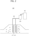
- FIG. 2 is a conceptual view illustrating automatic catalyst-regeneration equipment in the power generation system according to an embodiment of the invention.
- a power generation system 1000 includes a boiler 100, environmental equipment 200, and a chimney 300.
- the boiler 100 includes a combustion space in which a burner is installed.
- fuel is supplied to the burner, and air flows into the combustion space.
- the boiler 100 generates steam with thermal energy in the combustion space.
- the fuel supplied to the boiler 100 may include fossil fuel such as pulverized coal or heavy oil.
- the burner when pulverized coal is used as fossil fuel, the burner is provided as a pulverized-coal burner to spray air and pulverized coal into the combustion space.
- the pulverized-coal burner may include a low NOx burner to which a low NOx (nitrogen oxide) combustion process is applied.
- the low NOx burner is merely to describe an embodiment of the invention, and various kinds of burners may be used.
- power generation equipment (not shown) is connected to the boiler and produces electricity based on steam provided by the boiler 100.
- the environmental equipment 200 may include a first denitrifier 210, a first rotary air-preheater 220, an electric precipitator 230, a desulfurizer 240, a second denitrifier 250, and a catalyst regenerator 260.
- the environmental equipment 200 is connected to the boiler 100 and forms a course to discharge exhaust gas, from which pollutants are removed, to the atmosphere through the chimney 300.
- the first denitrifier 210 is placed between the boiler 100 and the first rotary air-preheater 220 and receives exhaust gas from the boiler 100.
- the first denitrifier 210 may receive the exhaust gas which is primarily denitrified by a selective non-catalytic reduction (SNCR) device or NOx burner installed in the boiler 100.
- SNCR selective non-catalytic reduction
- NOx burner installed in the boiler 100.
- the first denitrifier 210 secondarily denitrifies the exhaust gas received from the boiler 100.
- the first denitrifier 210 may include selective catalytic reduction (SCR) device.
- SCR selective catalytic reduction
- the first denitrifier 210 sprays ammonia, urea or the like reductant to the exhaust gas, thereby converting nitrogen oxide into nonpolluting water and nitrogen on the catalyst.
- the first rotary air-preheater (or gas air heater, GAH) is placed between the first denitrifier 210 and the electric precipitator 230.
- the first rotary air-preheater 220 recovers waste heat from the exhaust gas provided by the denitrifier. Further, the first rotary air-preheater 220 previously heats air flowing into the combustion space, thereby improving a combustion efficiency of the boiler 100. In other words, the first rotary air-preheater 220 heats air supplied into the boiler 100 and used for combustion with remaining heat previously used for the combustion.
- the electric precipitator 230 is provided as a low low-temperature electric precipitator between the first rotary air-preheater 220 and the desulfurizer 240 and collects dust from the exhaust gas provided by the first rotary air-preheater 220.
- the electric precipitator 230 may be provided as a dust collector based on electrostatic separation.
- dust in the exhaust gas is charged by a metal wire of a cathode, and the charged dust is adhered to an anode shaped like a plate or tube.
- the electric precipitator 230 is suitable for large-scale exhaust gas treatment and may additionally include a bag filter to improve a dust-collection efficiency by a hybrid manner.
- this is merely for describing an embodiment of the disclosure, and does not limit the kinds of dust collectors.
- the desulfurizer 240 is provided between the electric precipitator 230 and the second denitrifier 250 and desulfurizes the exhaust gas provided by the electric precipitator 230.
- the desulfurizer 240 may internally include a cyclone for gas/liquid contact enhancement to improve a desulfurization efficiency.
- the desulfurizer 240 may be enlarged as compared with a conventional one and additionally include a plurality of gypsum sludge spraying nozzles or the like to keep a desulfurization efficiency of 98% or higher.
- the desulfurizer 240 may include a mist eliminator in an inside upper portion thereof to prevent gypsum slurry from spilling out.
- sulfur dioxide of the exhaust gas is neutralized by reaction with limestone in the desulfurizer 240 and changed into gypsum. In this case, the gypsum may be recycled for industrial use.
- the second denitrifier 250 is provided between the desulfurizer 240 and the chimney 300 and receives the exhaust gas from the desulfurizer 240.
- the second denitrifier 250 may include a low-temperature SCR device.
- the second denitrifier 250 denitrifies the exhaust gas provided by the desulfurizer 240 so that the denitrified exhaust gas can be discharged to the atmosphere through the chimney 300.
- a first heat exchanger 11 is provided between the first rotary air-preheater 220 and the electric precipitator 230.
- the first heat exchanger 11 is connected to a second heat exchanger 12 provided between the desulfurizer 240 and the second denitrifier 250.
- the first heat exchanger 11 and the second heat exchanger 12 may be embodied by tube-type gas gas heaters (GGH).
- GGH tube-type gas gas heaters
- the first heat exchanger 11 cools the exhaust gas
- the second heat exchanger 12 heats the exhaust gas.
- a third heat exchanger 13 is provided between the second denitrifier 250 and the chimney 300.
- the third heat exchanger 13 is connected to a fourth heat exchanger 14 provided on a course where air for combustion flows into the first rotary air-preheater 220.
- the third heat exchanger 13 may be provided as an air preheater that recovers waste heat from the exhaust gas, and thus air to be supplied to the boiler 100 and used for combustion is heated by the fourth heat exchanger 14.
- the third heat exchanger 13 and the fourth heat exchanger 14 may be embodied by rotary or tubular heat exchangers.
- the catalyst regenerator 260 may be connected to at least one of the first denitrifier 210 and the second denitrifier 250.
- the catalyst regenerator 260 sprays catalyst regeneration materials to catalysts 211 and 251 when the catalysts 211 and 251 are poisoned during the operations of the denitrifiers, thereby preventing the life of the catalysts 211 and 251 from being shortened.
- the catalyst regenerator 260 may spray the catalyst regeneration materials including dry ice to the catalysts.
- the catalyst regenerator 260 may include a catalyst-regeneration material feeder 261, a sprayer 262, and a spraying nozzle 263.
- the catalyst-regeneration material feeder 261 may be placed outside the denitrifier and feed the catalyst regeneration material such as dry ice pellet into the sprayer 262. Further, the sprayer 262 sprays the catalyst regeneration material to the catalysts 211 and 251. To this end, the sprayer 262 is connected to the spraying nozzle 263 neighboring on the catalysts 211 and 251 outside the denitrifiers and supplies the catalyst regeneration material to the spraying nozzle 263.
- the spraying nozzle 263 includes a single spraying hole or a plurality of spraying holes to uniformly spray the catalyst regeneration material to the entire surfaces of the catalysts 211 and 251.
- the spraying nozzle 263 may be connected to a motor, an actuator or the like motive power source, and move up and down inside the denitrifier.
- the catalyst regenerator 260 has an advantage of preventing the catalyst from being poisoned and shortened in life.
- the catalyst regenerator 260 in an embodiment of the invention is connected to at least one of the first denitrifier 210 and the second denitrifier 250.
- the catalyst regenerator 260 may be installed only in the second denitrifier 250, and may be installed in both the first denitrifier 210 and the second denitrifier 250 when coal quality is bad.
- the catalyst regenerator 260 sprays dry ice.
- the catalyst regenerator may alternately spray dry ice and hot steam.
- the environmental equipment 200 includes the first denitrifier 210 and the second denitrifier 250. However, this is merely for describing an embodiment of the invention, and the environmental equipment 200 may include only the second denitrifier 250 without the first denitrifier 210 as necessary.
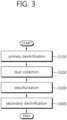
- FIG. 3 is a flowchart showing operations of environmental equipment according to an embodiment of the invention.
- the environmental equipment 200 removes pollutants from exhaust gas provided by the boiler 100 and discharges the exhaust gas to the atmosphere through the chimney 300.
- the exhaust gas discharged from the boiler 100 is primarily denitrified in the first denitrifier 210 (S100).
- the first denitrifier 210 sprays a reductant to the exhaust gas so that nitrogen oxide can be converted into water and nitrogen.
- the exhaust gas discharged from the first denitrifier 210 is provided to the first rotary air-preheater 220.
- the exhaust gas provided to the first rotary air-preheater 220 has a temperature of about 360 degrees.
- the first rotary air-preheater 220 recovers waste heat from the exhaust gas and heats air, which will be provided to the boiler 100 and used for combustion, with the waste heat.
- the exhaust gas is supplied from the first rotary air-preheater 220 to the electric precipitator 230 via the first heat exchanger 11.
- the exhaust gas having a temperature of about 180-250 degrees is provided to the first heat exchanger 11, and the first heat exchanger 11 recovers heat from the exhaust gas so that the exhaust gas having a temperature of about 90 degrees, for example, 80 - 100 degrees can be provided to the electric precipitator 230.
- the electric precipitator 230 collects dust from the exhaust gas (S200).
- the exhaust gas, from which dust has been removed, is provided to the desulfurizer 240.
- the exhaust gas provided to the desulfurizer 240 may be maintained at a temperature of about 90.
- the desulfurizer 240 desulfurizes the exhaust gas (S300).
- sulfur dioxide of the exhaust gas is neutralized by reaction with limestone and changed into gypsum, and the desulfurizer 240 supplies the desulfurized exhaust gas to the second denitrifier 250.
- the exhaust gas passed through the desulfurizer 240 may have a temperature of about 50 degrees.
- the second heat exchanger 12 placed between the desulfurizer 240 and the second denitrifier 250 heats the exhaust gas provided by the desulfurizer 240 so that the exhaust gas having a temperature of about 150-200 degrees can be provided to the second denitrifier 250.
- the second heat exchanger 12 does not need a burner because the waste heat of the exhaust gas is recycled to heat the exhaust gas.
- the environmental equipment 200 excludes or does not employ the burner, thereby reducing fuel costs by more than 10 billion won per year in the case of a 500MW-class coal-fired power station.
- the second denitrifier 250 secondarily denitrifies the exhaust gas (S400).
- the second denitrifier 250 secondarily denitrifies the exhaust gas based on low-temperature SCR, so that the secondarily denitrified exhaust gas can be provided toward the chimney 300.
- the exhaust gas may have a temperature of about 150-200 degrees.
- the third heat exchanger 13 recovers waste heat from the exhaust gas provided toward the chimney, and thus the exhaust gas having a temperature of about 60-85 degrees is discharged through the chimney 300.
- the fourth heat exchanger 14 additionally raises the temperature of air, which will be provided to the first rotary air-preheater 220 and used for combustion, by 25 degrees or higher, based on the waste heat recovered in the third heat exchanger 13.
- the environmental equipment 200 improves the efficiency of the boiler by about 1 % or more, and has an effect on reducing costs by 3.3 billion won per year in the case of the 500MW-class coal-fired power station.
- the environmental equipment according to the invention and the power generation system including the same have effect on reducing operating costs and facilitating easy installation and operation of the system because the exhaust gas is heated based on the waste heat of the exhaust gas without the burner.
Landscapes
- Engineering & Computer Science (AREA)
- Chemical & Material Sciences (AREA)
- Mechanical Engineering (AREA)
- General Engineering & Computer Science (AREA)
- Environmental & Geological Engineering (AREA)
- Chemical Kinetics & Catalysis (AREA)
- General Chemical & Material Sciences (AREA)
- Oil, Petroleum & Natural Gas (AREA)
- Health & Medical Sciences (AREA)
- Biomedical Technology (AREA)
- Analytical Chemistry (AREA)
- Combustion & Propulsion (AREA)
- Life Sciences & Earth Sciences (AREA)
- Sustainable Development (AREA)
- Chimneys And Flues (AREA)
- Exhaust Gas Treatment By Means Of Catalyst (AREA)
- Air Supply (AREA)
Description
- The invention relates to environmental equipment and a power generation system including the same, and more particularly to environmental equipment for reducing discharge of pollutants and a power generation system including the same.
- Numerous thermoelectric power plants generally operate based on coal or petroleum. In particular, with recently tightened regulations on environmental pollution, environmental equipment capable of reducing discharge of pollutants has been increasingly researched, developed and spread.
- The related art of such environmental equipment has already been disclosed in
Korean Patent Publication No. 2017-0142377 (titled "POLLUTANT REMOVAL APPARATUS AND COMBINED CYCLE POWER GENERATION SYSTEM" and published on December 28, 2017 -
EP 1 780 466 A1 deals with providing a method for removing gaseous mercury in flue gas that make it possible to remove mercury in flue gas extremely satisfactorily while handling is made easy and cost increases are kept under control. In order to accomplish this object, this document adopts the method of removing gaseous mercury in flue gas, in which, after water-insoluble mercury in the flue gas is converted into water-soluble mercury by placing the flue gas in contact with a solid catalyst formed by a metal oxide, wet-type absorption is performed on the water-soluble mercury. -
EP 0 148 741 A1 describes a process of thermally treating flue gases which come from a boiler system and are conducted through two series-connected flue gas aftertreating plants, wherein the second flue gas aftertreating plant is an NOx - removing plant and is operated at a higher flue gas temperature than the first flue gas aftertreating plant, and of thermally treating combustion air to be supplied to the boiler system. This process is characterized in that heat of the flue gases is used to reheat the flue gases and to preheat air. - However, acceptable pollutant-discharge standards are tightened, and thus high-efficiency technology of using a denitrifying catalyst is required to reduce nitrogen oxide, i.e., a precursor of fine dust, which has come up as an environmental issue, into a few PPM levels. Therefore, the conventional environmental equipment includes a denitrifier based on selective catalytic reduction (SCR), which is placed after a flue gas desulfurizer (FGD). The denitrifier based on the SCR needs to use a burner for heating exhaust gas in order to raise the temperature of the exhaust gas. Therefore, the conventional environmental equipment has a problem in that operating costs are excessively increased.
- An aspect of the invention is to provide environmental equipment, of which operating costs are significantly reduced, and a power generation system including the same.
- To achieve the aspect of the invention, there is provided a power generation system including: a boiler; an electric generator which produces electricity based on steam generated in the boiler; a first denitrifier which receives exhaust gas from the boiler and denitrifies the exhaust gas by spraying a reductant to the exhaust gas; a low low-temperature electric precipitator which collects dust from the exhaust gas provided from the first denitrifier; a second denitrifier which secondarily denitrifies the exhaust gas by spraying the reductant to the exhaust gas provided from the low low-temperature electric precipitator and provides the exhaust gas toward a chimney; a first heat exchanger which is provided between the first denitrifier and the low low-temperature electric precipitator and cools the exhaust gas provided to the low low-temperature electric precipitator; and a second heat exchanger which is connected to the first heat exchanger between the low low-temperature electric precipitator and the second denitrifier and heats the exhaust gas provided to the second denitrifier.
- The second denitrifier may secondarily denitrify the exhaust gas based on a low temperature selective catalytic reduction (SCR).
- The first heat exchanger may cool the exhaust gas, to be provided to the low low-temperature electric precipitator, to have a temperature of 80-100 degrees, and the second heat exchanger may heat the exhaust gas, to be provided to the second denitrifier, to have a temperature of 150-200 degrees.
- The power generation system may further include: a third heat exchanger which is provided between the second denitrifier and the chimney and cools the exhaust gas to be provided to the chimney; and a fourth heat exchanger which is connected to the third heat exchanger and heats air to be provided to the boiler and used for combustion.
- The power generation system may further include a catalyst regenerator which is connected to at least one of the first denitrifier and the second denitrifier and supplies a catalyst regeneration material toward a catalyst in the denitrifier.
- The catalyst regenerator may spray dry ice toward the catalyst.
- The catalyst regenerator may alternately spray dry ice and hot steam toward the catalyst.
- The catalyst regenerator may include: a sprayer which is provided outside the denitrifier and supplies the catalyst regeneration material from the outside, and a spraying nozzle which is extended from the sprayer to an inside of the denitrifier and moves up and down inside the denitrifier by a motive power source to spray the catalyst regeneration material toward the catalyst.
- The catalyst regenerator may spray the catalyst regeneration material to the catalyst when the catalyst is poisoned.
- Meanwhile, the environmental equipment for connecting to a boiler of a power generation system according to the invention includes: an electric generator which produces electricity based on steam generated in the boiler; a first denitrifier which receives exhaust gas from the boiler and denitrifies the exhaust gas by spraying a reductant to the exhaust gas; a low low-temperature electric precipitator which collects dust from the exhaust gas provided from the first denitrifier; a second denitrifier which secondarily denitrifies the exhaust gas by spraying the reductant to the exhaust gas provided from the low low-temperature electric precipitator and provides the exhaust gas toward a chimney; a first heat exchanger which is provided between the first denitrifier and the low low-temperature electric precipitator and cools the exhaust gas provided to the low low-temperature electric precipitator; and a second heat exchanger which is connected to the first heat exchanger between the low low-temperature electric precipitator and the second denitrifier and heats the exhaust gas provided to the second denitrifier.
- The second denitrifier may secondarily denitrify the exhaust gas based on a low temperature SCR.
- The first heat exchanger may cool the exhaust gas, to be provided to the low low-temperature electric precipitator, to have a temperature of 80-100 degrees, and the second heat exchanger may heat the exhaust gas, to be provided to the second denitrifier, to have a temperature of 150-200 degrees.
- The environmental equipment may further include: a third heat exchanger which is provided between the second denitrifier and the chimney and cools the exhaust gas to be provided to the chimney; and a fourth heat exchanger which is connected to the third heat exchanger and heats air to be provided to the boiler and used for combustion.
- The environmental equipment may further include a catalyst regenerator which is connected to at least one of the first denitrifier and the second denitrifier and supplies a catalyst regeneration material toward a catalyst in the denitrifier.
- The catalyst regenerator may spray dry ice toward the catalyst.
- The catalyst regenerator may alternately spray dry ice and hot steam toward the catalyst.
- The catalyst regenerator may include: a sprayer which is provided outside the denitrifier and supplies the catalyst regeneration material from the outside, and a spraying nozzle which is extended from the sprayer to an inside of the denitrifier and moves up and down inside the denitrifier by a motive power source to spray the catalyst regeneration material toward the catalyst.
- The catalyst regenerator may spray the catalyst regeneration material to the catalyst when the catalyst is poisoned.
- An environmental equipment according to the invention and a power generation system including the same, in which exhaust gas is heated based on waste heat of the exhaust gas without a burner, have effects on reducing operating costs and facilitating easy installation and operation of the system.
- The technical effects of the invention are not limited to the foregoing effects, and other technical effects will become apparent to those skilled in the art through the following descriptions.
-
-
FIG. 1 is a conceptual view schematically illustrating a power generation system according to an embodiment of the invention. -
FIG. 2 is a conceptual view illustrating automatic catalyst-regeneration equipment in the power generation system according to an embodiment of the invention, and -
FIG. 3 is a flowchart showing operations of environmental equipment according to an embodiment of the invention. - Below, embodiments of the invention will be described with reference to the accompanying drawings. However, the embodiments are not limited to embodiments set forth herein, but may be variously given to complete the invention and help a person having ordinary knowledge in the art to fully understand the scope of the invention.
- The shapes, etc. of elements in the accompanying drawings may be exaggerated for clearer description, and like numerals refer to like elements throughout the accompanying drawings.
-
FIG. 1 is a conceptual view schematically illustrating a power generation system according to an embodiment of the invention, andFIG. 2 is a conceptual view illustrating automatic catalyst-regeneration equipment in the power generation system according to an embodiment of the invention. - As shown in
FIGS. 1 and2 , apower generation system 1000 according to an embodiment of the invention includes aboiler 100,environmental equipment 200, and achimney 300. - First, the
boiler 100 includes a combustion space in which a burner is installed. In theboiler 100, fuel is supplied to the burner, and air flows into the combustion space. Thus, theboiler 100 generates steam with thermal energy in the combustion space. In this case, the fuel supplied to theboiler 100 may include fossil fuel such as pulverized coal or heavy oil. - For example, when pulverized coal is used as fossil fuel, the burner is provided as a pulverized-coal burner to spray air and pulverized coal into the combustion space. In this case, the pulverized-coal burner may include a low NOx burner to which a low NOx (nitrogen oxide) combustion process is applied. However, the low NOx burner is merely to describe an embodiment of the invention, and various kinds of burners may be used. Further, power generation equipment (not shown) is connected to the boiler and produces electricity based on steam provided by the
boiler 100. - Meanwhile, the
environmental equipment 200 may include afirst denitrifier 210, a first rotary air-preheater 220, anelectric precipitator 230, adesulfurizer 240, asecond denitrifier 250, and acatalyst regenerator 260. In this case, theenvironmental equipment 200 is connected to theboiler 100 and forms a course to discharge exhaust gas, from which pollutants are removed, to the atmosphere through thechimney 300. - First, the
first denitrifier 210 is placed between theboiler 100 and the first rotary air-preheater 220 and receives exhaust gas from theboiler 100. In this case, thefirst denitrifier 210 may receive the exhaust gas which is primarily denitrified by a selective non-catalytic reduction (SNCR) device or NOx burner installed in theboiler 100. Thus, thefirst denitrifier 210 secondarily denitrifies the exhaust gas received from theboiler 100. - Here, the
first denitrifier 210 may include selective catalytic reduction (SCR) device. Thus, the first denitrifier 210 sprays ammonia, urea or the like reductant to the exhaust gas, thereby converting nitrogen oxide into nonpolluting water and nitrogen on the catalyst. - Meanwhile, the first rotary air-preheater (or gas air heater, GAH) is placed between the
first denitrifier 210 and theelectric precipitator 230. Thus, the first rotary air-preheater 220 recovers waste heat from the exhaust gas provided by the denitrifier. Further, the first rotary air-preheater 220 previously heats air flowing into the combustion space, thereby improving a combustion efficiency of theboiler 100. In other words, the first rotary air-preheater 220 heats air supplied into theboiler 100 and used for combustion with remaining heat previously used for the combustion. - Further, the
electric precipitator 230 is provided as a low low-temperature electric precipitator between the first rotary air-preheater 220 and the desulfurizer 240 and collects dust from the exhaust gas provided by the first rotary air-preheater 220. Here, theelectric precipitator 230 may be provided as a dust collector based on electrostatic separation. Thus, dust in the exhaust gas is charged by a metal wire of a cathode, and the charged dust is adhered to an anode shaped like a plate or tube. Theelectric precipitator 230 is suitable for large-scale exhaust gas treatment and may additionally include a bag filter to improve a dust-collection efficiency by a hybrid manner. However, this is merely for describing an embodiment of the disclosure, and does not limit the kinds of dust collectors. - Meanwhile, the
desulfurizer 240 is provided between theelectric precipitator 230 and thesecond denitrifier 250 and desulfurizes the exhaust gas provided by theelectric precipitator 230. Here, thedesulfurizer 240 may internally include a cyclone for gas/liquid contact enhancement to improve a desulfurization efficiency. Further, thedesulfurizer 240 may be enlarged as compared with a conventional one and additionally include a plurality of gypsum sludge spraying nozzles or the like to keep a desulfurization efficiency of 98% or higher. Further, thedesulfurizer 240 may include a mist eliminator in an inside upper portion thereof to prevent gypsum slurry from spilling out. Thus, sulfur dioxide of the exhaust gas is neutralized by reaction with limestone in thedesulfurizer 240 and changed into gypsum. In this case, the gypsum may be recycled for industrial use. - Meanwhile, the
second denitrifier 250 is provided between thedesulfurizer 240 and thechimney 300 and receives the exhaust gas from thedesulfurizer 240. In this case, thesecond denitrifier 250 may include a low-temperature SCR device. Thus, thesecond denitrifier 250 denitrifies the exhaust gas provided by thedesulfurizer 240 so that the denitrified exhaust gas can be discharged to the atmosphere through thechimney 300. - Meanwhile, a
first heat exchanger 11 is provided between the first rotary air-preheater 220 and theelectric precipitator 230. Thefirst heat exchanger 11 is connected to asecond heat exchanger 12 provided between thedesulfurizer 240 and thesecond denitrifier 250. Here, thefirst heat exchanger 11 and thesecond heat exchanger 12 may be embodied by tube-type gas gas heaters (GGH). Thefirst heat exchanger 11 cools the exhaust gas, and thesecond heat exchanger 12 heats the exhaust gas. Further, athird heat exchanger 13 is provided between thesecond denitrifier 250 and thechimney 300. Thethird heat exchanger 13 is connected to afourth heat exchanger 14 provided on a course where air for combustion flows into the first rotary air-preheater 220. Here, thethird heat exchanger 13 may be provided as an air preheater that recovers waste heat from the exhaust gas, and thus air to be supplied to theboiler 100 and used for combustion is heated by thefourth heat exchanger 14. Thethird heat exchanger 13 and thefourth heat exchanger 14 may be embodied by rotary or tubular heat exchangers. - Further, the
catalyst regenerator 260 may be connected to at least one of thefirst denitrifier 210 and thesecond denitrifier 250. The catalyst regenerator 260 sprays catalyst regeneration materials to catalysts 211 and 251 when the catalysts 211 and 251 are poisoned during the operations of the denitrifiers, thereby preventing the life of the catalysts 211 and 251 from being shortened. In this case, thecatalyst regenerator 260 may spray the catalyst regeneration materials including dry ice to the catalysts. - The catalyst regenerator 260 may include a catalyst-
regeneration material feeder 261, asprayer 262, and a sprayingnozzle 263. The catalyst-regeneration material feeder 261 may be placed outside the denitrifier and feed the catalyst regeneration material such as dry ice pellet into thesprayer 262. Further, thesprayer 262 sprays the catalyst regeneration material to the catalysts 211 and 251. To this end, thesprayer 262 is connected to the sprayingnozzle 263 neighboring on the catalysts 211 and 251 outside the denitrifiers and supplies the catalyst regeneration material to the sprayingnozzle 263. Here, the sprayingnozzle 263 includes a single spraying hole or a plurality of spraying holes to uniformly spray the catalyst regeneration material to the entire surfaces of the catalysts 211 and 251. The sprayingnozzle 263 may be connected to a motor, an actuator or the like motive power source, and move up and down inside the denitrifier. - Thus, the
catalyst regenerator 260 has an advantage of preventing the catalyst from being poisoned and shortened in life. - The catalyst regenerator 260 in an embodiment of the invention is connected to at least one of the
first denitrifier 210 and thesecond denitrifier 250. However, thecatalyst regenerator 260 may be installed only in thesecond denitrifier 250, and may be installed in both thefirst denitrifier 210 and thesecond denitrifier 250 when coal quality is bad. - In an embodiment of the invention, the
catalyst regenerator 260 sprays dry ice. However, this is merely for describing an embodiment of the invention, and the catalyst regenerator may alternately spray dry ice and hot steam. - Further, the
environmental equipment 200 according to an embodiment of the invention includes thefirst denitrifier 210 and thesecond denitrifier 250. However, this is merely for describing an embodiment of the invention, and theenvironmental equipment 200 may include only thesecond denitrifier 250 without thefirst denitrifier 210 as necessary. - Below, operations of the environmental equipment according to an embodiment of the invention will be described in detail. Here, repetitive descriptions to the foregoing elements will be avoided, and like numerals refer to like elements.
-
FIG. 3 is a flowchart showing operations of environmental equipment according to an embodiment of the invention. - As shown in
FIG. 3 , theenvironmental equipment 200 according to an embodiment of the invention removes pollutants from exhaust gas provided by theboiler 100 and discharges the exhaust gas to the atmosphere through thechimney 300. - First, the exhaust gas discharged from the
boiler 100 is primarily denitrified in the first denitrifier 210 (S100). In this case, thefirst denitrifier 210 sprays a reductant to the exhaust gas so that nitrogen oxide can be converted into water and nitrogen. - Further, the exhaust gas discharged from the
first denitrifier 210 is provided to the first rotary air-preheater 220. In this case, the exhaust gas provided to the first rotary air-preheater 220 has a temperature of about 360 degrees. Here, the first rotary air-preheater 220 recovers waste heat from the exhaust gas and heats air, which will be provided to theboiler 100 and used for combustion, with the waste heat. - Then, the exhaust gas is supplied from the first rotary air-
preheater 220 to theelectric precipitator 230 via thefirst heat exchanger 11. In this case, the exhaust gas having a temperature of about 180-250 degrees is provided to thefirst heat exchanger 11, and thefirst heat exchanger 11 recovers heat from the exhaust gas so that the exhaust gas having a temperature of about 90 degrees, for example, 80 - 100 degrees can be provided to theelectric precipitator 230. - Then, the
electric precipitator 230 collects dust from the exhaust gas (S200). The exhaust gas, from which dust has been removed, is provided to thedesulfurizer 240. In this case, the exhaust gas provided to thedesulfurizer 240 may be maintained at a temperature of about 90. - Further, the
desulfurizer 240 desulfurizes the exhaust gas (S300). Thus, sulfur dioxide of the exhaust gas is neutralized by reaction with limestone and changed into gypsum, and thedesulfurizer 240 supplies the desulfurized exhaust gas to thesecond denitrifier 250. In this case, the exhaust gas passed through thedesulfurizer 240 may have a temperature of about 50 degrees. - Meanwhile, the
second heat exchanger 12 placed between thedesulfurizer 240 and thesecond denitrifier 250 heats the exhaust gas provided by thedesulfurizer 240 so that the exhaust gas having a temperature of about 150-200 degrees can be provided to thesecond denitrifier 250. Here, thesecond heat exchanger 12 does not need a burner because the waste heat of the exhaust gas is recycled to heat the exhaust gas. Thus, theenvironmental equipment 200 excludes or does not employ the burner, thereby reducing fuel costs by more than 10 billion won per year in the case of a 500MW-class coal-fired power station. - Meanwhile, the
second denitrifier 250 secondarily denitrifies the exhaust gas (S400). Here, thesecond denitrifier 250 secondarily denitrifies the exhaust gas based on low-temperature SCR, so that the secondarily denitrified exhaust gas can be provided toward thechimney 300. Here, the exhaust gas may have a temperature of about 150-200 degrees. - Meanwhile, the
third heat exchanger 13 recovers waste heat from the exhaust gas provided toward the chimney, and thus the exhaust gas having a temperature of about 60-85 degrees is discharged through thechimney 300. In this case, thefourth heat exchanger 14 additionally raises the temperature of air, which will be provided to the first rotary air-preheater 220 and used for combustion, by 25 degrees or higher, based on the waste heat recovered in thethird heat exchanger 13. Thus, theenvironmental equipment 200 improves the efficiency of the boiler by about 1 % or more, and has an effect on reducing costs by 3.3 billion won per year in the case of the 500MW-class coal-fired power station. - Accordingly, the environmental equipment according to the invention and the power generation system including the same have effect on reducing operating costs and facilitating easy installation and operation of the system because the exhaust gas is heated based on the waste heat of the exhaust gas without the burner.
- The embodiments of the invention described above and illustrated in the accompanying drawings should not be construed as limiting the technical idea of the invention. The scope of the invention is limited only by matters disclosed in the appended claims, and various improvements and changes can be made by a person having ordinary knowledge in the art without departing from the technical idea of the invention.
- Therefore, such improvements and changes fall within the scope of the invention as long as they are apparent to those skilled in the art.
Claims (15)
- A power generation system (1000) comprising:a boiler (100)an electric generator which produces electricity based on steam generated in the boiler (100);a first denitrifier (210) which receives exhaust gas from the boiler (100) and denitrifies the exhaust gas by spraying a reductant to the exhaust gas;a low low-temperature electric precipitator (230) which collects dust from the exhaust gas provided from the first denitrifier (210);a second denitrifier (250) which secondarily denitrifies the exhaust gas by spraying the reductant to the exhaust gas provided from the low low-temperature electric precipitator (230) and provides the exhaust gas toward a chimney (300);a first heat exchanger (11) which is provided between the first denitrifier (210) and the low low-temperature electric precipitator (230) and cools the exhaust gas provided to the low low-temperature electric precipitator (230); anda second heat exchanger (12) which is connected to the first heat exchanger (11) between the low low-temperature electric precipitator (230) and the second denitrifier (250) and heats the exhaust gas provided to the second denitrifier (250).
- The power generation system (1000) of claim 1, wherein the second denitrifier (250) secondarily denitrifies the exhaust gas based on a low temperature selective catalytic reduction (SCR).
- The power generation system (1000) of claim 1, whereinthe first heat exchanger (11) cools the exhaust gas, to be provided to the low low-temperature electric precipitator (230), to have a temperature of 80-100 degrees, andthe second heat exchanger (12) heats the exhaust gas, to be provided to the second denitrifier (250), to have a temperature of 150-200 degrees.
- The power generation system (1000) of claim 1, further comprising:a third heat exchanger (13) which is provided between the second denitrifier (250) and the chimney (300) and cools the exhaust gas to be provided to the chimney (300); anda fourth heat exchanger (14) which is connected to the third heat exchanger (13) and heats air to be provided to the boiler (100) and used for combustion.
- The power generation system (1000) of claim 1, further comprising a catalyst regenerator (260) which is connected to at least one of the first denitrifier (210) and the second denitrifier (250) and supplies a catalyst regeneration material toward a catalyst in the denitrifier (210, 250).
- The power generation system (1000) of claim 5, wherein the catalyst regenerator (260) sprays dry ice toward the catalyst.
- The power generation system (1000) of claim 5, wherein the catalyst regenerator (260) alternately sprays dry ice and hot steam toward the catalyst.
- The power generation system (1000) of claim 5, wherein the catalyst regenerator (260) comprises:a sprayer (262) which is provided outside the denitrifier (210, 250) and supplies the catalyst regeneration material from the outside, anda spraying nozzle (263) which is extended from the sprayer (262) to an inside of the denitrifier (210, 250) and moves up and down inside the denitrifier (210, 250) by a motive power source to spray the catalyst regeneration material toward the catalyst.
- The power generation system (1000) of claim 5, wherein the catalyst regenerator (260) sprays the catalyst regeneration material to the catalyst when the catalyst is poisoned.
- Environmental equipment (200) for connecting to a boiler (100) of a power generation system (1000), comprising:an electric generator which produces electricity based on steam generated in the boiler (100);a first denitrifier (210) which receives exhaust gas from the boiler (100) and denitrifies the exhaust gas by spraying a reductant to the exhaust gas;a low low-temperature electric precipitator (230) which collects dust from the exhaust gas provided from the first denitrifier (210);a second denitrifier (250) which secondarily denitrifies the exhaust gas by spraying the reductant to the exhaust gas provided from the low low-temperature electric precipitator (230) and provides the exhaust gas toward a chimney (300);a first heat exchanger (11) which is provided between the first denitrifier (210) and the low low-temperature electric precipitator (230) and cools the exhaust gas provided to the low low-temperature electric precipitator (230); anda second heat exchanger (12) which is connected to the first heat exchanger (11) between the low low-temperature electric precipitator (230) and the second denitrifier (250) and heats the exhaust gas provided to the second denitrifier (250).
- The environmental equipment (200) of claim 10, wherein the second denitrifier (250) secondarily denitrifies the exhaust gas based on a low temperature selective catalytic reduction (SCR).
- The environmental equipment (200) of claim 10, whereinthe first heat exchanger (11) cools the exhaust gas, to be provided to the low low-temperature electric precipitator (230), to have a temperature of 80-100 degrees, andthe second heat exchanger (12) heats the exhaust gas, to be provided to the second denitrifier (250), to have a temperature of 150-200 degrees.
- The environmental equipment (200) of claim 10, further comprising:a third heat exchanger (13) which is provided between the second denitrifier (250) and the chimney (300) and cools the exhaust gas to be provided to the chimney; (300) anda fourth heat exchanger (14) which is connected to the third heat exchanger (13) and heats air to be provided to the boiler (100) and used for combustion.
- The environmental equipment (200) of claim 10, further comprising a catalyst regenerator (260) which is connected to at least one of the first denitrifier (210) and the second denitrifier (250) and supplies a catalyst regeneration material toward a catalyst in the denitrifier (210, 250).
- The environmental equipment (200) of claim 14, wherein the catalyst regenerator (260) sprays dry ice toward the catalyst.
Applications Claiming Priority (2)
| Application Number | Priority Date | Filing Date | Title |
|---|---|---|---|
| KR1020190054542A KR102178815B1 (en) | 2019-05-09 | 2019-05-09 | Environmental equipment and power generation system including the same |
| PCT/KR2020/002288 WO2020226272A1 (en) | 2019-05-09 | 2020-02-18 | Environmental equipment and power generation system using same |
Publications (3)
| Publication Number | Publication Date |
|---|---|
| EP3967928A1 EP3967928A1 (en) | 2022-03-16 |
| EP3967928A4 EP3967928A4 (en) | 2023-06-07 |
| EP3967928B1 true EP3967928B1 (en) | 2024-12-04 |
Family
ID=73051523
Family Applications (1)
| Application Number | Title | Priority Date | Filing Date |
|---|---|---|---|
| EP20802359.8A Active EP3967928B1 (en) | 2019-05-09 | 2020-02-18 | Environmental equipment and power generation system using same |
Country Status (6)
| Country | Link |
|---|---|
| US (1) | US11712658B2 (en) |
| EP (1) | EP3967928B1 (en) |
| KR (1) | KR102178815B1 (en) |
| CN (1) | CN217178554U (en) |
| PL (1) | PL3967928T3 (en) |
| WO (1) | WO2020226272A1 (en) |
Families Citing this family (3)
| Publication number | Priority date | Publication date | Assignee | Title |
|---|---|---|---|---|
| PH12022551217A1 (en) * | 2019-12-18 | 2023-06-14 | Sumitomo SHI FW Energia Oy | Arrangement and method for operating a steam boiler system |
| KR102231419B1 (en) * | 2020-11-12 | 2021-03-23 | 이범섭 | Combustion Flue Gas Treatment System with High Denitrification Efficiency |
| KR102550735B1 (en) * | 2021-09-14 | 2023-07-05 | 한국생산기술연구원 | Active nitrogen oxide precursor reduction system for fine dust reduction and nitrogen oxide reduction method using the same |
Family Cites Families (9)
| Publication number | Priority date | Publication date | Assignee | Title |
|---|---|---|---|---|
| AT379677B (en) * | 1983-10-27 | 1986-02-10 | Simmering Graz Pauker Ag | METHOD AND DEVICE FOR THE THERMAL TREATMENT OF SMOKE GASES FROM A BOILER SYSTEM |
| AU2003280632A1 (en) * | 2002-11-05 | 2004-06-07 | Babcock-Hitachi Kabushiki Kaisha | Exhaust gas treating apparatus |
| JP4503378B2 (en) * | 2004-07-15 | 2010-07-14 | 株式会社Ihi | Method and apparatus for removing gaseous mercury in exhaust gas |
| CA2672580C (en) * | 2006-12-27 | 2015-02-03 | Babcock-Hitachi Kabushiki Kaisha | Exhaust gas treating method and apparatus |
| KR20080090359A (en) * | 2008-07-21 | 2008-10-08 | 삼성에버랜드 주식회사 | Boiler system improves denitrification and thermal efficiency |
| KR101566505B1 (en) * | 2015-05-12 | 2015-11-05 | 주식회사 지스코 | Method for regenerating scr catalyst |
| JP6763539B2 (en) * | 2016-03-30 | 2020-09-30 | 三菱パワー株式会社 | Exhaust gas treatment system |
| KR101853188B1 (en) | 2016-06-17 | 2018-04-27 | 한국전력공사 | Pollutant removal apparatus and Combined cycle power generation system |
| CN108367275B (en) * | 2016-09-12 | 2021-09-21 | 中国电力株式会社 | Denitration catalyst and method for producing same |
-
2019
- 2019-05-09 KR KR1020190054542A patent/KR102178815B1/en active Active
-
2020
- 2020-02-18 WO PCT/KR2020/002288 patent/WO2020226272A1/en not_active Ceased
- 2020-02-18 US US17/607,260 patent/US11712658B2/en active Active
- 2020-02-18 PL PL20802359.8T patent/PL3967928T3/en unknown
- 2020-02-18 CN CN202090000547.0U patent/CN217178554U/en active Active
- 2020-02-18 EP EP20802359.8A patent/EP3967928B1/en active Active
Also Published As
| Publication number | Publication date |
|---|---|
| CN217178554U (en) | 2022-08-12 |
| US20220234003A1 (en) | 2022-07-28 |
| KR102178815B1 (en) | 2020-11-13 |
| EP3967928A1 (en) | 2022-03-16 |
| EP3967928A4 (en) | 2023-06-07 |
| WO2020226272A1 (en) | 2020-11-12 |
| PL3967928T3 (en) | 2025-04-07 |
| US11712658B2 (en) | 2023-08-01 |
Similar Documents
| Publication | Publication Date | Title |
|---|---|---|
| KR101918663B1 (en) | Power generation system | |
| US8808652B2 (en) | Biomass boiler SCR NOx and CO reduction system | |
| EP2480831B1 (en) | Integrated boiler and air pollution control systems | |
| EP3967928B1 (en) | Environmental equipment and power generation system using same | |
| KR101224203B1 (en) | Integrated dust-collecting, de-SOx, de-NOx, and wasteheat recovery system | |
| CN204395778U (en) | A kind of ultra-clean exhaust system for fluidized-bed combustion boiler | |
| US7618604B2 (en) | Method and apparatus for removing gaseous mercury in flue gas | |
| CN104437082A (en) | Ultra-clean discharge system and method for fluidized bed boiler | |
| WO2004023040A1 (en) | Exhaust smoke-processing system | |
| KR102374520B1 (en) | Combustion System Including Energy-Saving Flue Gas Treatment Facility | |
| KR20150067292A (en) | Exhaust gas treatment system and method | |
| SG185072A1 (en) | System and method for improved heat recovery from flue gases with high so3 concentrations | |
| WO2014129402A1 (en) | Exhaust gas treatment system and exhaust gas treatment method | |
| WO2014103682A1 (en) | Exhaust gas processing equipment and gas turbine power generation system using same | |
| KR101166476B1 (en) | A system for controlling exhaust gas | |
| KR100606438B1 (en) | Flue gas treatment system to recover waste heat of flue gas discharged from the rear end of SCR reactor | |
| KR102077738B1 (en) | Power generation system | |
| CN218065982U (en) | Cement kiln waste gas discharge system for reducing content of nitrogen oxides | |
| CN216125455U (en) | Flue gas synergistic reaction device | |
| KR102231419B1 (en) | Combustion Flue Gas Treatment System with High Denitrification Efficiency | |
| CN213375915U (en) | Cement kiln exhaust gas nitrogen oxide low concentration emission system | |
| US5354364A (en) | High efficiency advanced dry scrubber | |
| KR102161823B1 (en) | Environmental equipment and power generation system including the same | |
| JPH105542A (en) | Flue gas treatment system | |
| CN114797446B (en) | Flue gas co-reaction device and flue gas dust removal, desulfurization and denitrification control method |
Legal Events
| Date | Code | Title | Description |
|---|---|---|---|
| STAA | Information on the status of an ep patent application or granted ep patent |
Free format text: STATUS: THE INTERNATIONAL PUBLICATION HAS BEEN MADE |
|
| PUAI | Public reference made under article 153(3) epc to a published international application that has entered the european phase |
Free format text: ORIGINAL CODE: 0009012 |
|
| STAA | Information on the status of an ep patent application or granted ep patent |
Free format text: STATUS: REQUEST FOR EXAMINATION WAS MADE |
|
| 17P | Request for examination filed |
Effective date: 20211112 |
|
| AK | Designated contracting states |
Kind code of ref document: A1 Designated state(s): AL AT BE BG CH CY CZ DE DK EE ES FI FR GB GR HR HU IE IS IT LI LT LU LV MC MK MT NL NO PL PT RO RS SE SI SK SM TR |
|
| DAV | Request for validation of the european patent (deleted) | ||
| DAX | Request for extension of the european patent (deleted) | ||
| A4 | Supplementary search report drawn up and despatched |
Effective date: 20230510 |
|
| RIC1 | Information provided on ipc code assigned before grant |
Ipc: F23L 15/02 20060101ALI20230503BHEP Ipc: F23L 15/04 20060101ALI20230503BHEP Ipc: F23J 15/02 20060101ALI20230503BHEP Ipc: F02G 5/02 20060101ALI20230503BHEP Ipc: F23J 15/04 20060101AFI20230503BHEP |
|
| GRAP | Despatch of communication of intention to grant a patent |
Free format text: ORIGINAL CODE: EPIDOSNIGR1 |
|
| STAA | Information on the status of an ep patent application or granted ep patent |
Free format text: STATUS: GRANT OF PATENT IS INTENDED |
|
| INTG | Intention to grant announced |
Effective date: 20240731 |
|
| GRAS | Grant fee paid |
Free format text: ORIGINAL CODE: EPIDOSNIGR3 |
|
| GRAA | (expected) grant |
Free format text: ORIGINAL CODE: 0009210 |
|
| STAA | Information on the status of an ep patent application or granted ep patent |
Free format text: STATUS: THE PATENT HAS BEEN GRANTED |
|
| AK | Designated contracting states |
Kind code of ref document: B1 Designated state(s): AL AT BE BG CH CY CZ DE DK EE ES FI FR GB GR HR HU IE IS IT LI LT LU LV MC MK MT NL NO PL PT RO RS SE SI SK SM TR |
|
| REG | Reference to a national code |
Ref country code: CH Ref legal event code: EP |
|
| REG | Reference to a national code |
Ref country code: DE Ref legal event code: R096 Ref document number: 602020042621 Country of ref document: DE |
|
| REG | Reference to a national code |
Ref country code: IE Ref legal event code: FG4D |
|
| REG | Reference to a national code |
Ref country code: LT Ref legal event code: MG9D |
|
| REG | Reference to a national code |
Ref country code: NL Ref legal event code: MP Effective date: 20241204 |
|
| PG25 | Lapsed in a contracting state [announced via postgrant information from national office to epo] |
Ref country code: HR Free format text: LAPSE BECAUSE OF FAILURE TO SUBMIT A TRANSLATION OF THE DESCRIPTION OR TO PAY THE FEE WITHIN THE PRESCRIBED TIME-LIMIT Effective date: 20241204 |
|
| PG25 | Lapsed in a contracting state [announced via postgrant information from national office to epo] |
Ref country code: FI Free format text: LAPSE BECAUSE OF FAILURE TO SUBMIT A TRANSLATION OF THE DESCRIPTION OR TO PAY THE FEE WITHIN THE PRESCRIBED TIME-LIMIT Effective date: 20241204 |
|
| PG25 | Lapsed in a contracting state [announced via postgrant information from national office to epo] |
Ref country code: BG Free format text: LAPSE BECAUSE OF FAILURE TO SUBMIT A TRANSLATION OF THE DESCRIPTION OR TO PAY THE FEE WITHIN THE PRESCRIBED TIME-LIMIT Effective date: 20241204 |
|
| PG25 | Lapsed in a contracting state [announced via postgrant information from national office to epo] |
Ref country code: ES Free format text: LAPSE BECAUSE OF FAILURE TO SUBMIT A TRANSLATION OF THE DESCRIPTION OR TO PAY THE FEE WITHIN THE PRESCRIBED TIME-LIMIT Effective date: 20241204 |
|
| PG25 | Lapsed in a contracting state [announced via postgrant information from national office to epo] |
Ref country code: NO Free format text: LAPSE BECAUSE OF FAILURE TO SUBMIT A TRANSLATION OF THE DESCRIPTION OR TO PAY THE FEE WITHIN THE PRESCRIBED TIME-LIMIT Effective date: 20250304 |
|
| PG25 | Lapsed in a contracting state [announced via postgrant information from national office to epo] |
Ref country code: LV Free format text: LAPSE BECAUSE OF FAILURE TO SUBMIT A TRANSLATION OF THE DESCRIPTION OR TO PAY THE FEE WITHIN THE PRESCRIBED TIME-LIMIT Effective date: 20241204 Ref country code: GR Free format text: LAPSE BECAUSE OF FAILURE TO SUBMIT A TRANSLATION OF THE DESCRIPTION OR TO PAY THE FEE WITHIN THE PRESCRIBED TIME-LIMIT Effective date: 20250305 |
|
| PG25 | Lapsed in a contracting state [announced via postgrant information from national office to epo] |
Ref country code: RS Free format text: LAPSE BECAUSE OF FAILURE TO SUBMIT A TRANSLATION OF THE DESCRIPTION OR TO PAY THE FEE WITHIN THE PRESCRIBED TIME-LIMIT Effective date: 20250304 |
|
| PG25 | Lapsed in a contracting state [announced via postgrant information from national office to epo] |
Ref country code: NL Free format text: LAPSE BECAUSE OF FAILURE TO SUBMIT A TRANSLATION OF THE DESCRIPTION OR TO PAY THE FEE WITHIN THE PRESCRIBED TIME-LIMIT Effective date: 20241204 |
|
| REG | Reference to a national code |
Ref country code: AT Ref legal event code: MK05 Ref document number: 1748538 Country of ref document: AT Kind code of ref document: T Effective date: 20241204 |
|
| PG25 | Lapsed in a contracting state [announced via postgrant information from national office to epo] |
Ref country code: SM Free format text: LAPSE BECAUSE OF FAILURE TO SUBMIT A TRANSLATION OF THE DESCRIPTION OR TO PAY THE FEE WITHIN THE PRESCRIBED TIME-LIMIT Effective date: 20241204 |
|
| PG25 | Lapsed in a contracting state [announced via postgrant information from national office to epo] |
Ref country code: IS Free format text: LAPSE BECAUSE OF FAILURE TO SUBMIT A TRANSLATION OF THE DESCRIPTION OR TO PAY THE FEE WITHIN THE PRESCRIBED TIME-LIMIT Effective date: 20250404 |
|
| PG25 | Lapsed in a contracting state [announced via postgrant information from national office to epo] |
Ref country code: PT Free format text: LAPSE BECAUSE OF FAILURE TO SUBMIT A TRANSLATION OF THE DESCRIPTION OR TO PAY THE FEE WITHIN THE PRESCRIBED TIME-LIMIT Effective date: 20250404 |
|
| PG25 | Lapsed in a contracting state [announced via postgrant information from national office to epo] |
Ref country code: EE Free format text: LAPSE BECAUSE OF FAILURE TO SUBMIT A TRANSLATION OF THE DESCRIPTION OR TO PAY THE FEE WITHIN THE PRESCRIBED TIME-LIMIT Effective date: 20241204 |
|
| PG25 | Lapsed in a contracting state [announced via postgrant information from national office to epo] |
Ref country code: AT Free format text: LAPSE BECAUSE OF FAILURE TO SUBMIT A TRANSLATION OF THE DESCRIPTION OR TO PAY THE FEE WITHIN THE PRESCRIBED TIME-LIMIT Effective date: 20241204 Ref country code: RO Free format text: LAPSE BECAUSE OF FAILURE TO SUBMIT A TRANSLATION OF THE DESCRIPTION OR TO PAY THE FEE WITHIN THE PRESCRIBED TIME-LIMIT Effective date: 20241204 |
|
| PG25 | Lapsed in a contracting state [announced via postgrant information from national office to epo] |
Ref country code: SK Free format text: LAPSE BECAUSE OF FAILURE TO SUBMIT A TRANSLATION OF THE DESCRIPTION OR TO PAY THE FEE WITHIN THE PRESCRIBED TIME-LIMIT Effective date: 20241204 |
|
| PG25 | Lapsed in a contracting state [announced via postgrant information from national office to epo] |
Ref country code: CZ Free format text: LAPSE BECAUSE OF FAILURE TO SUBMIT A TRANSLATION OF THE DESCRIPTION OR TO PAY THE FEE WITHIN THE PRESCRIBED TIME-LIMIT Effective date: 20241204 |
|
| PG25 | Lapsed in a contracting state [announced via postgrant information from national office to epo] |
Ref country code: IT Free format text: LAPSE BECAUSE OF FAILURE TO SUBMIT A TRANSLATION OF THE DESCRIPTION OR TO PAY THE FEE WITHIN THE PRESCRIBED TIME-LIMIT Effective date: 20241204 |
|
| REG | Reference to a national code |
Ref country code: DE Ref legal event code: R097 Ref document number: 602020042621 Country of ref document: DE |
|
| PG25 | Lapsed in a contracting state [announced via postgrant information from national office to epo] |
Ref country code: SE Free format text: LAPSE BECAUSE OF FAILURE TO SUBMIT A TRANSLATION OF THE DESCRIPTION OR TO PAY THE FEE WITHIN THE PRESCRIBED TIME-LIMIT Effective date: 20241204 |
|
| PG25 | Lapsed in a contracting state [announced via postgrant information from national office to epo] |
Ref country code: MC Free format text: LAPSE BECAUSE OF FAILURE TO SUBMIT A TRANSLATION OF THE DESCRIPTION OR TO PAY THE FEE WITHIN THE PRESCRIBED TIME-LIMIT Effective date: 20241204 |
|
| REG | Reference to a national code |
Ref country code: CH Ref legal event code: PL |
|
| PG25 | Lapsed in a contracting state [announced via postgrant information from national office to epo] |
Ref country code: DK Free format text: LAPSE BECAUSE OF FAILURE TO SUBMIT A TRANSLATION OF THE DESCRIPTION OR TO PAY THE FEE WITHIN THE PRESCRIBED TIME-LIMIT Effective date: 20241204 |
|
| PLBE | No opposition filed within time limit |
Free format text: ORIGINAL CODE: 0009261 |
|
| STAA | Information on the status of an ep patent application or granted ep patent |
Free format text: STATUS: NO OPPOSITION FILED WITHIN TIME LIMIT |
|
| PG25 | Lapsed in a contracting state [announced via postgrant information from national office to epo] |
Ref country code: LU Free format text: LAPSE BECAUSE OF NON-PAYMENT OF DUE FEES Effective date: 20250218 |
|
| PG25 | Lapsed in a contracting state [announced via postgrant information from national office to epo] |
Ref country code: CH Free format text: LAPSE BECAUSE OF NON-PAYMENT OF DUE FEES Effective date: 20250228 |
|
| 26N | No opposition filed |
Effective date: 20250905 |
|
| GBPC | Gb: european patent ceased through non-payment of renewal fee |
Effective date: 20250304 |
|
| REG | Reference to a national code |
Ref country code: BE Ref legal event code: MM Effective date: 20250228 |
|
| PG25 | Lapsed in a contracting state [announced via postgrant information from national office to epo] |
Ref country code: GB Free format text: LAPSE BECAUSE OF NON-PAYMENT OF DUE FEES Effective date: 20250304 |
|
| PG25 | Lapsed in a contracting state [announced via postgrant information from national office to epo] |
Ref country code: FR Free format text: LAPSE BECAUSE OF NON-PAYMENT OF DUE FEES Effective date: 20250228 |
|
| PG25 | Lapsed in a contracting state [announced via postgrant information from national office to epo] |
Ref country code: BE Free format text: LAPSE BECAUSE OF NON-PAYMENT OF DUE FEES Effective date: 20250228 |
|
| PG25 | Lapsed in a contracting state [announced via postgrant information from national office to epo] |
Ref country code: IE Free format text: LAPSE BECAUSE OF NON-PAYMENT OF DUE FEES Effective date: 20250218 |
|
| PGFP | Annual fee paid to national office [announced via postgrant information from national office to epo] |
Ref country code: DE Payment date: 20251217 Year of fee payment: 7 |
|
| PGFP | Annual fee paid to national office [announced via postgrant information from national office to epo] |
Ref country code: PL Payment date: 20260127 Year of fee payment: 7 |