EP3967859A1 - Electronic unit for controlling and driving an electrical motor - Google Patents
Electronic unit for controlling and driving an electrical motor Download PDFInfo
- Publication number
- EP3967859A1 EP3967859A1 EP20196002.8A EP20196002A EP3967859A1 EP 3967859 A1 EP3967859 A1 EP 3967859A1 EP 20196002 A EP20196002 A EP 20196002A EP 3967859 A1 EP3967859 A1 EP 3967859A1
- Authority
- EP
- European Patent Office
- Prior art keywords
- housing
- electronics
- circuit board
- printed circuit
- unit according
- Prior art date
- Legal status (The legal status is an assumption and is not a legal conclusion. Google has not performed a legal analysis and makes no representation as to the accuracy of the status listed.)
- Withdrawn
Links
Images


Classifications
-
- F—MECHANICAL ENGINEERING; LIGHTING; HEATING; WEAPONS; BLASTING
- F02—COMBUSTION ENGINES; HOT-GAS OR COMBUSTION-PRODUCT ENGINE PLANTS
- F02B—INTERNAL-COMBUSTION PISTON ENGINES; COMBUSTION ENGINES IN GENERAL
- F02B39/00—Component parts, details, or accessories relating to, driven charging or scavenging pumps, not provided for in groups F02B33/00 - F02B37/00
- F02B39/02—Drives of pumps; Varying pump drive gear ratio
- F02B39/08—Non-mechanical drives, e.g. fluid drives having variable gear ratio
- F02B39/10—Non-mechanical drives, e.g. fluid drives having variable gear ratio electric
-
- F—MECHANICAL ENGINEERING; LIGHTING; HEATING; WEAPONS; BLASTING
- F02—COMBUSTION ENGINES; HOT-GAS OR COMBUSTION-PRODUCT ENGINE PLANTS
- F02B—INTERNAL-COMBUSTION PISTON ENGINES; COMBUSTION ENGINES IN GENERAL
- F02B37/00—Engines characterised by provision of pumps driven at least for part of the time by exhaust
- F02B37/04—Engines with exhaust drive and other drive of pumps, e.g. with exhaust-driven pump and mechanically-driven second pump
- F02B37/10—Engines with exhaust drive and other drive of pumps, e.g. with exhaust-driven pump and mechanically-driven second pump at least one pump being alternatively or simultaneously driven by exhaust and other drive, e.g. by pressurised fluid from a reservoir or an engine-driven pump
-
- F—MECHANICAL ENGINEERING; LIGHTING; HEATING; WEAPONS; BLASTING
- F02—COMBUSTION ENGINES; HOT-GAS OR COMBUSTION-PRODUCT ENGINE PLANTS
- F02B—INTERNAL-COMBUSTION PISTON ENGINES; COMBUSTION ENGINES IN GENERAL
- F02B39/00—Component parts, details, or accessories relating to, driven charging or scavenging pumps, not provided for in groups F02B33/00 - F02B37/00
- F02B39/005—Cooling of pump drives
-
- F—MECHANICAL ENGINEERING; LIGHTING; HEATING; WEAPONS; BLASTING
- F04—POSITIVE - DISPLACEMENT MACHINES FOR LIQUIDS; PUMPS FOR LIQUIDS OR ELASTIC FLUIDS
- F04B—POSITIVE-DISPLACEMENT MACHINES FOR LIQUIDS; PUMPS
- F04B35/00—Piston pumps specially adapted for elastic fluids and characterised by the driving means to their working members, or by combination with, or adaptation to, specific driving engines or motors, not otherwise provided for
- F04B35/04—Piston pumps specially adapted for elastic fluids and characterised by the driving means to their working members, or by combination with, or adaptation to, specific driving engines or motors, not otherwise provided for the means being electric
-
- F—MECHANICAL ENGINEERING; LIGHTING; HEATING; WEAPONS; BLASTING
- F04—POSITIVE - DISPLACEMENT MACHINES FOR LIQUIDS; PUMPS FOR LIQUIDS OR ELASTIC FLUIDS
- F04B—POSITIVE-DISPLACEMENT MACHINES FOR LIQUIDS; PUMPS
- F04B39/00—Component parts, details, or accessories, of pumps or pumping systems specially adapted for elastic fluids, not otherwise provided for in, or of interest apart from, groups F04B25/00 - F04B37/00
- F04B39/12—Casings; Cylinders; Cylinder heads; Fluid connections
- F04B39/121—Casings
-
- F—MECHANICAL ENGINEERING; LIGHTING; HEATING; WEAPONS; BLASTING
- F04—POSITIVE - DISPLACEMENT MACHINES FOR LIQUIDS; PUMPS FOR LIQUIDS OR ELASTIC FLUIDS
- F04D—NON-POSITIVE-DISPLACEMENT PUMPS
- F04D25/00—Pumping installations or systems
- F04D25/02—Units comprising pumps and their driving means
- F04D25/06—Units comprising pumps and their driving means the pump being electrically driven
- F04D25/068—Mechanical details of the pump control unit
-
- H—ELECTRICITY
- H05—ELECTRIC TECHNIQUES NOT OTHERWISE PROVIDED FOR
- H05K—PRINTED CIRCUITS; CASINGS OR CONSTRUCTIONAL DETAILS OF ELECTRIC APPARATUS; MANUFACTURE OF ASSEMBLAGES OF ELECTRICAL COMPONENTS
- H05K7/00—Constructional details common to different types of electric apparatus
- H05K7/20—Modifications to facilitate cooling, ventilating, or heating
- H05K7/2089—Modifications to facilitate cooling, ventilating, or heating for power electronics, e.g. for inverters for controlling motor
-
- F—MECHANICAL ENGINEERING; LIGHTING; HEATING; WEAPONS; BLASTING
- F01—MACHINES OR ENGINES IN GENERAL; ENGINE PLANTS IN GENERAL; STEAM ENGINES
- F01P—COOLING OF MACHINES OR ENGINES IN GENERAL; COOLING OF INTERNAL-COMBUSTION ENGINES
- F01P2050/00—Applications
- F01P2050/30—Circuit boards
-
- F—MECHANICAL ENGINEERING; LIGHTING; HEATING; WEAPONS; BLASTING
- F01—MACHINES OR ENGINES IN GENERAL; ENGINE PLANTS IN GENERAL; STEAM ENGINES
- F01P—COOLING OF MACHINES OR ENGINES IN GENERAL; COOLING OF INTERNAL-COMBUSTION ENGINES
- F01P3/00—Liquid cooling
- F01P3/12—Arrangements for cooling other engine or machine parts
-
- F—MECHANICAL ENGINEERING; LIGHTING; HEATING; WEAPONS; BLASTING
- F04—POSITIVE - DISPLACEMENT MACHINES FOR LIQUIDS; PUMPS FOR LIQUIDS OR ELASTIC FLUIDS
- F04D—NON-POSITIVE-DISPLACEMENT PUMPS
- F04D29/00—Details, component parts, or accessories
- F04D29/40—Casings; Connections of working fluid
- F04D29/42—Casings; Connections of working fluid for radial or helico-centrifugal pumps
- F04D29/4206—Casings; Connections of working fluid for radial or helico-centrifugal pumps especially adapted for elastic fluid pumps
-
- F—MECHANICAL ENGINEERING; LIGHTING; HEATING; WEAPONS; BLASTING
- F05—INDEXING SCHEMES RELATING TO ENGINES OR PUMPS IN VARIOUS SUBCLASSES OF CLASSES F01-F04
- F05D—INDEXING SCHEME FOR ASPECTS RELATING TO NON-POSITIVE-DISPLACEMENT MACHINES OR ENGINES, GAS-TURBINES OR JET-PROPULSION PLANTS
- F05D2220/00—Application
- F05D2220/40—Application in turbochargers
-
- H—ELECTRICITY
- H05—ELECTRIC TECHNIQUES NOT OTHERWISE PROVIDED FOR
- H05K—PRINTED CIRCUITS; CASINGS OR CONSTRUCTIONAL DETAILS OF ELECTRIC APPARATUS; MANUFACTURE OF ASSEMBLAGES OF ELECTRICAL COMPONENTS
- H05K7/00—Constructional details common to different types of electric apparatus
- H05K7/20—Modifications to facilitate cooling, ventilating, or heating
- H05K7/20845—Modifications to facilitate cooling, ventilating, or heating for automotive electronic casings
- H05K7/20872—Liquid coolant without phase change
-
- Y—GENERAL TAGGING OF NEW TECHNOLOGICAL DEVELOPMENTS; GENERAL TAGGING OF CROSS-SECTIONAL TECHNOLOGIES SPANNING OVER SEVERAL SECTIONS OF THE IPC; TECHNICAL SUBJECTS COVERED BY FORMER USPC CROSS-REFERENCE ART COLLECTIONS [XRACs] AND DIGESTS
- Y02—TECHNOLOGIES OR APPLICATIONS FOR MITIGATION OR ADAPTATION AGAINST CLIMATE CHANGE
- Y02T—CLIMATE CHANGE MITIGATION TECHNOLOGIES RELATED TO TRANSPORTATION
- Y02T10/00—Road transport of goods or passengers
- Y02T10/10—Internal combustion engine [ICE] based vehicles
- Y02T10/12—Improving ICE efficiencies
Definitions
- the invention relates to an electronics unit for controlling and operating an electric motor, in particular for controlling an electric motor for driving a compressor, in particular a gas compressor, with an electronics housing in whose accommodation space power electronics for controlling the electric motor are accommodated, the electronics housing having a connection wall, with which the electronics housing can be coupled to an outer surface of a receiving housing in which the electric motor is arranged.
- Gas compressors within the meaning of the invention can in particular be exhaust gas turbochargers which have a turbine wheel and a compressor wheel.
- the electric motor is housed in a receiving housing of the exhaust gas turbocharger, which forms an outer surface.
- the electric motor is used to support the rotary motion of the compressor wheel.
- a compressor according to the invention can also be designed generally in the form of a turbocharger or compressor in such a way that it has a compressor wheel which is driven by the electric motor in order to supply a compressed gas flow to an internal combustion engine or a fuel cell.
- U.S. 7,352,077 B2 discloses an electrically assisted exhaust gas turbocharger.
- This has a drive shaft that carries a compressor wheel.
- a turbine is attached to the drive shaft.
- the turbine can be operated in a turbine housing of the turbocharger receiving housing.
- An exhaust gas flow is supplied to the turbine, causing the drive shaft and with it the compressor wheel to rotate.
- To support this rotation is in the An electric motor is installed in the housing.
- the receiving housing has a compressor housing which forms a spiral channel.
- the compressed air conveyed by the compressor wheel can be transported in the spiral channel and fed to an internal combustion engine.
- the compressor housing has a cylindrical extension.
- a ring-shaped electronics housing is pushed onto this.
- the electronics housing houses electronic components that are connected to the electric motor in order to supply it with alternating current.
- a DC voltage is supplied to the electronic components. This DC voltage can be converted into an AC voltage for the electric motor using the electronic components.
- a turbocharger which carries a compressor wheel on a drive shaft.
- the drive shaft and the compressor wheel are housed in a multi-part compressor housing.
- Electrical components are housed in a separate electronics housing.
- a cooling circuit which is routed through the electronics housing, is used to cool these structural units.
- the electronics housing has a housing opening opposite its connection wall, which is provided with a cover can be closed and through which the accommodation space is accessible, that a circuit board for accommodating at least part of the power electronics is arranged in the area behind the housing opening in the accommodation space and which has a longitudinal and a transverse extension, the longitudinal extension in the direction of the housing length and the transverse extension in the direction of the width of the housing, and that the connection wall runs inclined to the printed circuit board in the direction of the transverse extent of the printed circuit board, such that the installation space height of the receiving space running perpendicularly to the printed circuit board decreases at least in regions in the direction of the transverse extent from one side of the housing to the opposite side of the housing.
- the individual components of the power electronics for controlling the electric motor can be accommodated in a space-saving manner.
- Components with a large overall height can be arranged in the area of the side of the housing that provides the greatest installation space height.
- Components with a small overall height can then be positioned more in the area of the receiving space with the lowest overall height.
- the remaining electronic components can be arranged in areas that match their installation space height. In this way, a compact design can be implemented, also in conjunction with the receiving housing in which the electric motor is accommodated.
- the electronics housing can be positioned on the receiving housing in such a way that the receiving housing forms a kind of heat shield with respect to heat-emitting components, for example exhaust gas-carrying components.
- heat-emitting components for example exhaust gas-carrying components.
- the electronics housing can wrap around the receiving housing slightly for this purpose.
- the angle of wrap, with which the connection wall covers the receiving housing, is particularly advantageously less than 180° of the outer circumference of the receiving housing.
- a cross section of the electronics housing running in the direction of the transverse extension of the printed circuit board and in the direction of the installation space height has an approximately triangular or trapezoidal cross section.
- the hypotenuse of the triangle preferably has a preferably rounded, particularly preferably concave shape that is adapted to the outer surface of the receiving housing.
- the shape of the longest side of the trapezoidal cross-section is preferably adapted to the shape of the facing outer surface of the receiving housing, preferably rounded, particularly preferably concave.
- a triangular cross-sectional shape is present in particular whenever three housing walls at least partially surround the receiving space.
- a pentagonal, in particular a trapezoidal, cross-sectional shape is always given in particular when at least five housing walls surround the receiving space at least in regions.
- the connecting wall has a concave shape at least in certain areas.
- a shape is suitable in particular when the receiving housing has at least in some areas a cylindrical outer surface which faces the connection wall, in particular bears against it at least in some areas.
- the mounting position of the electronics housing on the receiving housing can be varied by the designer in this case, depending on the geometric conditions.
- the electronics housing can be positioned variably with respect to the circumferential direction of the receiving housing, which allows it to be used in different packages.
- At least one recess and/or at least one projection with attachment receptacles is provided in the area of the connecting wall, which forms a flat attachment surface.
- the electronics housing can be positioned without play with the flat mounting surface defined on a correspondingly designed mating surface of the receiving housing.
- the electronics housing can be securely fastened to the receiving housing with the fastening mounts, for example screw mounts.
- the fastening surface runs in the area of the center of gravity of the electronics unit or in the area of the centroid of the area of the cross section of the electronics housing intersecting the fastening area.
- An electronic unit according to the invention can in particular be such that at least two fastening surfaces are provided, with one fastening surface being provided in the end region of the connection wall in a region in which the receiving space has its smallest installation space height. In this way, in particular, a large spacing between the two fastening surfaces can be implemented.
- a controller is attached to the printed circuit board, which has a low-voltage connection or is assigned such a low-voltage connection, the low-voltage connection having a plug connector that is routed through the connection wall and is provided there in one area , in which the receiving space has its smallest installation space height.
- the connector is guided through one of the side walls in the area of the lowest height of the electronics housing.
- Simple assembly and maintenance of the electronics unit can be achieved in that the housing opening is dimensioned in such a way that the printed circuit board equipped with electronic components of the power electronics can be inserted through the housing opening into the receiving space.
- a space-optimized arrangement of the components of the power electronics results in particular when it is provided that one or more capacitors are arranged in the area in which the receiving space has its greatest overall height and/or that in the area in which the receiving space has its smallest overall height has one or more printed circuits on the printed circuit board and/or electronic switching elements, in particular MOSFETs, IGBTs or transistors, are arranged in a central area between the greatest and the smallest installation space height of the receiving space.
- the electronics housing has walls which delimit a coolant channel in such a way that the coolant channel runs in the area of the receiving space. In this way, the heat loss from the power electronics can be at least partially exchanged for a cooling medium guided in the coolant channel.
- At least one electrical component preferably the at least one electronic switch, rests against at least one of the walls delimiting the coolant channel, with heat-conducting paste preferably being held in the area between the wall and the electrical component .
- At least one of the electrical components of the power electronics is electrically conductively connected to the printed circuit board with contact terminals and is pressed against one of the walls of the electronics housing in a spring-loaded manner by means of a fastening clamp.
- the electronic switches are preferably attached in this way. The attachment is particularly preferably against one of the walls of the coolant channel.
- a possible variant of the invention can be such that at least one of the capacitors has an end facing away from the printed circuit board, and at least one EMC filter (electromagnetic compatibility filter) is arranged in the receiving space between this end and a side wall of the electronics housing, it being preferably provided that the EMC filter is electrically connected to the printed circuit board via a connecting line, and the connecting line is particularly preferably accommodated in a cable duct between an outside of the capacitor and a side wall of the electronics housing running transversely to the printed circuit board.
- EMC filter electromagtic compatibility filter
- an opening is arranged in the area of the connection wall, preferably in the area of a fastening surface, through which high-voltage lines are routed from the electronic switches to the connection of the electric motor. This enables direct wiring from the power electronics to the electric motor. This minimizes line losses. If the opening is arranged in the area of the fastening surface, any AC voltages that act on the power lines as a result of vibrations are minimized.
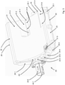
- FIG 1 an electric motor-assisted compressor 10, in particular a gas compressor, is shown.
- the compressor 10 is an exhaust gas turbocharger assisted by an electric motor.
- any other gas compressor supported or driven by an electric motor can also be considered within the scope of the invention.
- gas compressors can be turbochargers assisted by an electric motor or gas compressors assisted by an electric motor, which supply a motor unit, in particular an internal combustion engine or a fuel cell, with a compressed gas stream.
- the compressor 10 has a receiving housing 11 .
- An electric motor (not shown) is housed in this receiving housing.
- the electric motor drives a drive shaft 13.1 directly or indirectly.
- a compressor wheel 13 is attached to this drive shaft 13.1.
- the compressor wheel 13 is accommodated in a spiral housing 11.1, which is an integral or separate component of the receiving housing 11.
- a gas inlet 12 is assigned to this spiral housing 11.1.
- Fresh air can be drawn in via the gas inlet 12 .
- the fresh air is compressed by the compressor wheel 13 .
- the compressed air can be discharged via the gas outlet 11.2, for example supplied to an internal combustion engine.
- a turbine wheel is also coupled to the drive shaft 13.1, which is operated in the exhaust gas flow of the internal combustion engine and is driven by it.
- the turbine wheel is housed in a turbine housing.
- the turbine housing is an integral or separate component of the mounting housing 11.
- the drive shaft 13.1 can be driven by the electric motor arranged in the mounting housing 11 (e.g. turbocharger) or the kinetic energy introduced into the drive shaft 13.1 by the turbine wheel is supported by means of the electric motor (e.g. exhaust gas turbocharger ).
- the turbine housing has a turbine outlet 14 and a turbine inlet.
- the exhaust gas flow is fed to the turbine wheel via the turbine inlet.
- the exhaust gas flow is diverted into the exhaust system via the turbine outlet 14 .
- figure 1 shows that the receiving housing 11 has a connecting section 15 with an outer surface 15.1.
- the outer surface 15.1 is convexly curved at least in some areas. Within the scope of the invention, the outer surface 15.1 can extend over at least 45°, preferably at least over 60°, of the outer circumference of the receiving housing 11. The maximum extent of the outer surface 15.1 over the outer circumference of the receiving housing 11 should be chosen to be less than or equal to 180°.
- an electronics unit with an electronics housing 20 can be connected to the receiving housing 11 .
- Power electronics and a controller for controlling the power electronics are accommodated in electronics housing 20 .
- the electric motor can be supplied with electricity by means of the power electronics.
- the electronics housing 20 has a connection wall 21. With this connection wall 21, the electronics housing 20 is applied at least in sections to the outer surface 15.1 of the connecting section 15 of the receiving housing 11. About suitable The electronics housing 20 can then be connected to the receiving housing 11 by means of fastening means.
- the electronics housing 20 can be connected to differently designed receiving housings 11 of an exhaust gas turbocharger.
- the receiving housing 11 it is only necessary for the receiving housing 11 to provide a uniformly designed cut surface for coupling the electronics housing 20 in the area of its outer surface 15.1. In this way, a kit-like design can be achieved, which leads to a reduction in the number of parts.
- figure 1 indicates that the electronics housing 20 can be assigned a cooling circuit with a feed line 16.1 and a discharge line 16.2.
- a coolant is supplied to the electronics housing 20 via the supply line 16.1.
- the coolant can be routed through a coolant channel 47 of the electronics housing 20 and drained back out of the electronics housing 20 via the discharge line 16.2.
- the coolant absorbs the heat loss from the power electronics or part of the power electronics.
- the Figures 3 and 4 show the structure of the electronics housing 20 more clearly.
- the electronics housing 20 has a connection wall 21 .
- the electronics housing 20 can be applied to the outer surface 15.1 of the receiving housing 11.
- the outer surface 15.1 preferably has the same shape as the outer surface 15.1, at least in some areas.
- the outer surface 15.1 is convex and the connecting wall 21 is concave to match.
- Electronics housing 20 has two opposing side walls 24, 25 at the longitudinal ends of connecting wall 21. These two side walls 24, 25 each have an opening, one opening in first side wall 24 forming a coolant inlet 24.3.
- This coolant inlet 24.3 is connected to the supply line 16.1.
- the second side wall 25 has a coolant outlet 25.1.
- the coolant outlet 25.1 is connected to the discharge line 16.2.
- the coolant inlet 24.3 and the coolant outlet 25.1 are part of a coolant channel 47 which is routed through the electronics housing 20, as will be explained in more detail later.
- At least one of the side walls 24 can also be equipped with a coupling element 24.5.
- the coupling element 24.5 is used to connect a cable bushing 24.6.
- the cable bushing 24.6 has a bushing 24.7.
- a cable can be routed into the interior of electronics housing 20 through this passage 24.7.
- a cable carrying DC voltage with battery voltage can be routed into the interior of the electronics housing.
- the cable bushing 24.6 particularly preferably forms a sealed cable bushing.
- a strain relief for the cable can also be provided on this element.
- ground connection 24.4 it is also conceivable for a ground connection 24.4 to be present in the area of one of the side walls 24, 25.
- the power electronics can be grounded with this ground connection 24.4.
- the connecting wall 21 is adjoined at the transverse ends by side walls 23 , 26 .
- these side walls 23, 26 merge into the side walls 24, 25 at their longitudinal ends, preferably by means of rounded connecting sections.
- the electronics housing 20 forms a further side wall 26 in the area of its rear side.
- the side walls 24, 25, 23 and 26 enclose a housing opening.
- the receiving space of the electronics housing 20 is accessible through this housing opening.
- the housing opening can be closed with a cover 30.
- screw attachments 23.1, 24.2 and 26.1 are provided on the side walls 23, 24 and 26.
- This screw lugs 23.1, 24.2 and 26.1 can in particular as molded lateral thickening that protrude on the outside beyond the associated side walls 23, 24, 25 and 26, be formed.
- the electronics housing 20 has a trapezoidal cross section in side view.
- This trapezoidal cross section is formed by the connecting wall 21 and the side walls 22, 23 and 26 as well as by the cover 30.
- a triangular cross section can also be provided, for example. This triangular cross section would then be delimited by the connecting wall 21, the side wall 26 and the cover 30.
- FIG 3 shows that the electronics housing 20 has attachment surfaces 21.1 and 21.4 in the area of the connecting wall 21. These fastening surfaces 21.1 and 21.4 can in particular be designed as flat surfaces. Corresponding to at least one of these fastening surfaces 21.1 and 21.4, the receiving housing 11 can have a geometrically adapted mating surface in the area of the outer surface 15.1. how figure 3 further shows, the mounting surfaces 21.1 and 21.4 can be equipped with screw mounts 21.6. Fastening screws can then be passed through the screw receptacles 21.6 from the inside of the electronics housing 20 and screwed into threaded receptacles in the receptacle housing 11. The electronics housing 20 can be connected to the receiving housing 11 in this way.
- the fastening surface 21.1 is preferably arranged in the area of the projected centroid F of the cross section of the electronics housing (for example triangular cross section or trapezoidal cross section).
- the fastening surface 21.1 is particularly preferably arranged in the area of the center of mass M of the electronics unit, which results together with the fully assembled electronics housing and the power electronics arranged therein.
- the fastening surface 21.4 is arranged in the area of the side wall 23 and is therefore arranged at a large distance from the fastening surface 21.1. About these Spacing results in a large support spacing and thus secure attachment of the electronics housing 20.
- FIG 3 shows that an opening 21.3 can also be provided in the area of the connection wall 21, preferably in the area of the recess which forms the fastening surface 21.1.
- This breakthrough 21.3 is used to carry out the power supply cables that are fed to the electric motor.
- a power connection 21.5 can be held in the form of a plug contact in the area of the connection wall 21.
- This power connection 21.5 can form the low-voltage supply of an electrical circuit that is arranged inside the electronics housing 20. In the area of the connection wall 21, the power connection 21.5 is housed and secured against mechanical influences.
- an installation level E can be formed in the interior of the electronics housing 20, behind the opening closed by the cover 30.
- a printed circuit board 46 is arranged in this installation level E.
- the circuit board 46 can in particular run parallel to the opening or parallel to the plane of the cover 30 .
- the printed circuit board 46 has a printed circuit board top 46.1 which faces the connecting wall 21.
- a printed circuit board underside 46.2 faces the cover 30.
- the printed circuit board 46 has a transverse extent which figure 4 runs from left to right in the image plane, for example between the two side walls 23 and 26. The longitudinal extension of the printed circuit board 46 runs accordingly in the direction of the image depth figure 4 between the side walls 24 and 25.
- the circuit board 46 can house the electronic circuitry mentioned above.
- connection wall 21 runs in the direction of the transverse extent of the printed circuit board 46 inclined to the printed circuit board 46 in such a way that the installation space height of the receiving space running perpendicularly to the printed circuit board 46 decreases at least in regions in the direction of the transverse extent from one side of the housing to the opposite side of the housing.
- the greatest installation space height is in the area of the side wall 26 and the smallest installation space height is in the area of the side wall 23 .
- a plurality of capacitors 42 are arranged in the area of the greatest installation space height.
- the capacitors 42 are arranged next to one another in the direction of the length of the housing, which runs in the direction of the longitudinal extension of the printed circuit board 46 .
- the capacitors 42 can be arranged in such a way that they are arranged with their outer side 42.1 opposite the inner side of the side wall 26 and at a small distance from it.
- the opposite inner side 42.2 of the capacitors is assigned to the remaining receiving space, and accordingly also to the connecting wall 21.
- the capacitors 42 are preferably attached to the printed circuit board 46 and electrically contacted there. However, it is also conceivable that the capacitors 42 are arranged laterally next to the printed circuit board 46, such as figure 4 displays.
- the housing can be designed in such a way that a remaining free space is formed in the region between the upper side 42.3 of the capacitors 42 and the side wall 22.
- EMC filters 41 can be installed in this free space.
- a cable duct 24.1 in the form of a bulge in the side wall 24 may be incorporated.
- the circuit board 46 can be equipped with a controller. This controller can be arranged in the area of the lowest installation space height, ie in the vicinity of the side wall 23 .
- electronic switches 44 can be attached to the printed circuit board 46 and electrically contacted.
- the electronic switches 44 can be, for example, MOSFET switches or IGBT switches or other types of electronic switches 44 or transistors.
- the electronic switches 44 are in the direction of the longitudinal extent of the printed circuit board 46 (in the direction of the image depth according to figure 4 ) arranged side by side.
- the electronic switch 44 can in addition to their attachment to the circuit board 46 with another mechanical Attachment to the electronics housing 20 are attached.
- a mounting clamp 45 may preferably be used for this purpose.
- the fastening clamp 45 has a fastening section 45.1.
- the fastening clip 45 is connected to the electronics housing 20, preferably to the connecting wall 21, with this fastening section 45.1.
- the attachment section 45 is followed by a clamping section 45.2, which can be deflected in a resilient manner.
- the clamping section 45.2 ends with a run-up section 45.3.
- the clamping section 45.2 is resiliently deflected and presses on the facing outside of the switch 44. In this way, the switch 44 is held clamped between the clamping section 45.2 on one side and a wall 47.2 of the electronics housing 20.
- the wall 47.2 is preferably formed in one piece on the electronics housing 20; in particular, the wall 47.2 can be formed in one piece on the connecting wall 21.
- the wall 47.2 is particularly preferably part of a coolant channel 47 which runs within the electronics housing 20.
- the coolant channel 47 is bounded by walls 47.1, 47.2 and 47.3. As mentioned above, the coolant channel 47 communicates with the coolant inlet 24.3 and with the coolant outlet 25.1.
- the electronic switches are all arranged in a row along the longitudinal direction, so that they all contact the same wall 47.2 of the coolant channel 47.
- the electronic switches 44 it is also conceivable for the electronic switches 44 to be arranged in such a way that at least one electronic switch 44 makes contact with the opposite wall 47.1 of the coolant channel 47.
- the electronic switches 44 are then arranged in pairs on both sides of the coolant channel 47 .
- a free space is formed in the area between the capacitors 20 and the electronic switches 44 and can be used as a cable duct 43 .
- the motor cables coming from the switches 44 can be routed in this cable duct 43 .
- the cable duct 43 is spatially connected to the opening 21.3, through which the motor cables are routed and routed into the receiving housing 11. this is in figure 6 illustrated in more detail.
- the capacitors 42 extend almost over the entire depth of the receiving space.
- the EMC filters 41 on the other hand, have a length that is smaller than the installation space depth of the capacitors 42. In this way, free space remains in the receiving space following the cable duct 24.1, which is used for laying the power supply cables for the EMC filters 41 can.
- the electronics housing 20 is first attached with its connecting wall 21 to the outer surface 15.1 of the receiving housing 11.
- the fastening surfaces 21.1 and 21.4 are opposite corresponding mating surfaces of the receiving housing 11. From the inside of the electronics housing 20, fastening screws can be passed through the screw receptacles 21.6 and screwed into threaded receptacles in the receptacle housing 11. In this way, the electronics housing 20 is fixed to the receiving housing 11 .
- the fully equipped printed circuit board 46 can be inserted into the electronics housing 20 through the housing opening of the electronics housing, together with the capacitors 42, the electronic switches 44 and the microcontroller.
- the insertion movement of the printed circuit board 46 can be limited, for example, with projections 49 integrally formed on the inside of the electronics housing 20 .
- the projections 49 are also provided with screw mounts for fastening the printed circuit board 46 .
- the cover 30 is placed on the electronics housing 20 and the housing opening is thus closed.
- the electronics housing 20 does not have to be in the form of a separate housing. Rather, it is also conceivable that the electronics housing 20 is part of the receiving housing 11 .
- the EMC filters 41 do not necessarily have to be arranged in the area between the upper side 42.3 of the capacitors 42 and the side wall 42 facing them. Rather, the EMC filters 41 can also be arranged in another area of the receiving space of the electronics housing 20 between the capacitors 20 and the side wall 23 . In particular, it is conceivable that these EMC filters 41 are arranged between the capacitors 20 and the electronic switches 44 in order to be able to achieve a lower installation space height of the electronics housing 20 .
- the coolant channel 47 is routed in a straight line through the electronics housing 20 and thus runs in the direction of the longitudinal extension of the connection wall 21.
- the coolant channel 47 it is also conceivable for the coolant channel 47 to be routed through the electronics housing 20 in the form of one or more loops.
- the coolant channel 47 does not necessarily have to be introduced in one piece into the electronics housing 20 . Rather, it is conceivable that a separately mounted cooling channel is used.
- the coolant channel 47 is assigned cooling fins for improved heat transport, which are arranged in the area of the receiving space and/or in the line area formed by the coolant channel 47 .
- the invention is not limited to the embodiment described. Rather, within the scope of the invention it can also be provided that the electronic unit for controlling the electric motor for controlling an electric motor is used to drive a pump, in particular a hydrogen recirculation pump.
- the electronics unit is used to control an electrical generator that is driven by a turbine, in particular an exhaust gas turbine.
Abstract
Die Erfindung betrifft eine Elektronikeinheit zur Regelung eines Elektromotors, insbesondere zur Regelung eines Elektromotors zum Antrieb eines Verdichters, insbesondere Gasverdichters, mit einem Elektronikgehäuse (20), in dessen Aufnahmeraum eine Leistungselektronik zur Regelung des Elektromotors aufgenommen ist, wobei das Elektronikgehäuse (20) eine Anschlusswand (21) aufweist, mit der das Elektronikgehäuse (20) an eine Außenfläche (15.1) eines Aufnahmegehäuses, in dem ein Elektromotor untergebracht ist, ankoppelbar ist. Bei einer solchen Elektronikeinheit wird ein platzoptimiertes Elektronikgehäuse für eine Leistungselektronik zur Regelung eines Elektromotors eines Verdichters dann bereitstellt, wenn vorgesehen ist, dass das Elektronikgehäuse (20) gegenüberliegend der Anschlusswand (21) eine Gehäuseöffnung aufweist, die mit einer Abdeckung (30) verschließbar ist und durch die hindurch der Aufnahmeraum zugänglich ist, dass eine Leiterplatte (46) zur Aufnahme zumindest eines Teils der Leistungselektronik im Bereich hinter der Gehäuseöffnung im Aufnahmeraum angeordnet ist und die eine Längs- und eine Quererstreckung aufweist, wobei die Längserstreckung in Richtung der Gehäuselänge und die Quererstreckung in Richtung der Gehäusebreite verläuft, und dass die Anschlusswand (21) in Richtung der Quererstreckung der Leiterplatte (46) geneigt zu der Leiterplatte (46) verläuft, derart, dass die senkrecht zur Leiterplatte (46) verlaufende Bauraumhöhe des Aufnahmeraums in Richtung der Quererstreckung von einer Gehäuseseite zu der gegenüberliegenden Gehäuseseite zumindest bereichsweise abnimmt.The invention relates to an electronics unit for controlling an electric motor, in particular for controlling an electric motor for driving a compressor, in particular a gas compressor, with an electronics housing (20) in whose accommodation space power electronics for controlling the electric motor are accommodated, the electronics housing (20) having a connecting wall (21) with which the electronics housing (20) can be coupled to an outer surface (15.1) of a receiving housing in which an electric motor is accommodated. In such an electronics unit, a space-optimized electronics housing for power electronics for controlling an electric motor of a compressor is provided if it is provided that the electronics housing (20) has a housing opening opposite the connecting wall (21), which can be closed with a cover (30) and through which the accommodation space is accessible, that a circuit board (46) for accommodating at least part of the power electronics is arranged in the area behind the housing opening in the accommodation space and which has a longitudinal and a transverse extension, the longitudinal extension in the direction of the housing length and the transverse extension runs in the direction of the width of the housing, and that the connection wall (21) runs inclined to the printed circuit board (46) in the direction of the transverse extension of the printed circuit board (46), such that the installation space height of the receiving space running perpendicularly to the printed circuit board (46) in the direction of the transverse extension of one go äuseseite to the opposite side of the housing at least partially decreases.
Description
Die Erfindung betrifft eine Elektronikeinheit zur Regelung und zum Betreiben eines Elektromotors, insbesondere zur Regelung eines Elektromotors zum Antrieb eines Verdichters, insbesondere eines Gasverdichters, mit einem Elektronikgehäuse, in dessen Aufnahmeraum eine Leistungselektronik zur Regelung des Elektromotors aufgenommen ist, wobei das Elektronikgehäuse eine Anschlusswand aufweist, mit der das Elektronikgehäuse an eine Außenfläche eines Aufnahmegehäuses, in dem der Elektromotor angeordnet ist, ankoppelbar ist.The invention relates to an electronics unit for controlling and operating an electric motor, in particular for controlling an electric motor for driving a compressor, in particular a gas compressor, with an electronics housing in whose accommodation space power electronics for controlling the electric motor are accommodated, the electronics housing having a connection wall, with which the electronics housing can be coupled to an outer surface of a receiving housing in which the electric motor is arranged.
Gasverdichter im Sinne der Erfindung können insbesondere Abgasturbolader sein, die ein Turbinenrad und ein Verdichterrad aufweisen. Der Elektromotor ist dabei in einem Aufnahmegehäuse des Abgasturboladers untergebracht, welches eine Außenfläche bildet. Der Elektromotor dient dazu die Drehbewegung des Verdichterrads zu unterstützen.Gas compressors within the meaning of the invention can in particular be exhaust gas turbochargers which have a turbine wheel and a compressor wheel. The electric motor is housed in a receiving housing of the exhaust gas turbocharger, which forms an outer surface. The electric motor is used to support the rotary motion of the compressor wheel.
Ein erfindungsgemäßer Verdichter kann auch allgemein in Form eines Turboladers oder Kompressors derart gestaltet sein, dass er ein Verdichterrad aufweist, das von dem Elektromotor angetrieben wird, um einem Verbrennungsmotor oder einer Brennstoffzelle einen komprimierten Gasstrom zuzuführen.A compressor according to the invention can also be designed generally in the form of a turbocharger or compressor in such a way that it has a compressor wheel which is driven by the electric motor in order to supply a compressed gas flow to an internal combustion engine or a fuel cell.
Aus
Bei der Verwendung von elektrischen Motoren zum Antrieb oder der Unterstützung eines Gasverdichters, insbesondere eines Abgasturboladers oder eines Turboladers, spielt die platzsparende Anordnung der mitunter vergleichsweise großen Komponenten der Leistungselektronik zur Steuerung und Regelung des Elektromotors eine bedeutende Rolle. Zudem ist ein hinreichendes Wärmemanagement, das wegen der im Motorraum vorherrschenden Temperaturen und der Temperatursensitivität elektronischer Komponenten unerlässlich ist, bedeutsam.When using electric motors to drive or support a gas compressor, in particular an exhaust gas turbocharger or a turbocharger, the space-saving arrangement of the sometimes comparatively large components of the power electronics for controlling and regulating the electric motor plays an important role. Adequate heat management, which is essential due to the temperatures prevailing in the engine compartment and the temperature sensitivity of electronic components, is also important.
Es ist Aufgabe der Erfindung, eine Elektronikeinheit der eingangs erwähnten Art zu schaffen, welche ein platzoptimiertes Elektronikgehäuse für eine Leistungselektronik zur Regelung eines Elektromotors eines Verdichters bereitstellt.It is the object of the invention to create an electronics unit of the type mentioned at the outset, which provides a space-optimized electronics housing for power electronics for controlling an electric motor of a compressor.
Diese Aufgabe wird dadurch gelöst, dass das Elektronikgehäuse gegenüberliegend seiner Anschlusswand eine Gehäuseöffnung aufweist, die mit einer Abdeckung verschließbar ist und durch die hindurch der Aufnahmeraum zugänglich ist, dass eine Leiterplatte zur Aufnahme zumindest eines Teils der Leistungselektronik im Bereich hinter der Gehäuseöffnung im Aufnahmeraum angeordnet ist und die eine Längs- und eine Quererstreckung aufweist, wobei die Längserstreckung in Richtung der Gehäuselänge und die Quererstreckung in Richtung der Gehäusebreite verläuft, und dass die Anschlusswand in Richtung der Quererstreckung der Leiterplatte geneigt zu der Leiterplatte verläuft, derart, dass die senkrecht zur Leiterplatte verlaufende Bauraumhöhe des Aufnahmeraums in Richtung der Quererstreckung von einer Gehäuseseite zu der gegenüberliegenden Gehäuseseite zumindest bereichsweise abnimmt.This object is achieved in that the electronics housing has a housing opening opposite its connection wall, which is provided with a cover can be closed and through which the accommodation space is accessible, that a circuit board for accommodating at least part of the power electronics is arranged in the area behind the housing opening in the accommodation space and which has a longitudinal and a transverse extension, the longitudinal extension in the direction of the housing length and the transverse extension in the direction of the width of the housing, and that the connection wall runs inclined to the printed circuit board in the direction of the transverse extent of the printed circuit board, such that the installation space height of the receiving space running perpendicularly to the printed circuit board decreases at least in regions in the direction of the transverse extent from one side of the housing to the opposite side of the housing.
Bei einer solchen Elektronikeinheit können die einzelnen Komponenten der Leistungselektronik zur Ansteuerung des Elektromotors platzsparend untergebracht werden. Bauteile mit großer Bauhöhe können in dem Bereich der Gehäuseseite angeordnet werden, die die größte Bauraumhöhe zur Verfügung stellt. Bauteile mit kleiner Bauhöhe können dann eher im Bereich des Aufnahmeraums mit der geringsten Bauraumhöhe positioniert werden. Im Zwischenbereich zwischen diesen beiden Aufnahmeraum-Bereichen lassen sich die übrigen Elektronikkomponenten in Bereichen anordnen, die zu ihrer Bauraumhöhe passen. Auf diese Weise lässt sich, auch im Zusammenspiel mit dem Aufnahmegehäuse, in dem der Elektromotor untergebracht ist, eine kompakte Bauweise verwirklichen. Abhängig von der thermischen Belastung, die extern auf das Aufnahmegehäuse einwirkt, kann das Elektronikgehäuse am Aufnahmegehäuse so positioniert werden, dass das Aufnahmegehäuse eine Art Hitzeschild gegenüber wärmeabgebenden Komponenten, beispielsweise abgasführenden Bauteilen, bildet. Dies kann bei der vorliegenden Erfindung besonders wirksam gelöst werden. Beispielsweise kann zu diesem Zweck, aufgrund der kompakten Bauweise des Elektronikgehäuses, eine geringe Umschlingung des Aufnahmegehäuses durch das Elektronikgehäuse erreicht werden. Besonders vorteilhaft beträgt der Umschlingungswinkel, mit der die Anschlusswand das Aufnahmegehäuse überdeckt, weniger als 180° des Außenumfangs des Aufnahmegehäuses.With such an electronics unit, the individual components of the power electronics for controlling the electric motor can be accommodated in a space-saving manner. Components with a large overall height can be arranged in the area of the side of the housing that provides the greatest installation space height. Components with a small overall height can then be positioned more in the area of the receiving space with the lowest overall height. In the intermediate area between these two receiving space areas, the remaining electronic components can be arranged in areas that match their installation space height. In this way, a compact design can be implemented, also in conjunction with the receiving housing in which the electric motor is accommodated. Depending on the thermal load that acts externally on the receiving housing, the electronics housing can be positioned on the receiving housing in such a way that the receiving housing forms a kind of heat shield with respect to heat-emitting components, for example exhaust gas-carrying components. This can be solved particularly effectively in the present invention. For example, due to the compact design of the electronics housing, the electronics housing can wrap around the receiving housing slightly for this purpose. The angle of wrap, with which the connection wall covers the receiving housing, is particularly advantageously less than 180° of the outer circumference of the receiving housing.
Gemäß einer bevorzugten Erfindungsausgestaltung kann es vorgesehen sein, dass ein in Richtung der Quererstreckung der Leiterplatte und in Richtung der Bauraumhöhe verlaufender Querschnitt des Elektronikgehäuses näherungsweise einen dreieckförmigen oder trapezförmigen Querschnitt aufweist. Vorzugsweise weist dabei, bei einer dreieckförmigen Querschnittsform, die Hypotenuse des Dreiecks eine der Außenfläche des Aufnahmegehäuses angepasste, vorzugsweise gerundete, besonders bevorzugt konkave Form auf. Bei einer trapezförmigen Querschnittsform ist vorzugsweise die Form der längsten Seite des trapezförmigen Querschnitts auf die Form der zugekehrten Außenfläche des Aufnahmegehäuses angepasst, vorzugsweise gerundet, besonders bevorzugt konkav gestaltet.According to a preferred embodiment of the invention, it can be provided that a cross section of the electronics housing running in the direction of the transverse extension of the printed circuit board and in the direction of the installation space height has an approximately triangular or trapezoidal cross section. In the case of a triangular cross-sectional shape, the hypotenuse of the triangle preferably has a preferably rounded, particularly preferably concave shape that is adapted to the outer surface of the receiving housing. In the case of a trapezoidal cross-sectional shape, the shape of the longest side of the trapezoidal cross-section is preferably adapted to the shape of the facing outer surface of the receiving housing, preferably rounded, particularly preferably concave.
Im Sinne der Erfindung liegt eine dreieckförmige Querschnittsform insbesondere immer dann vor, wenn drei Gehäusewände den Aufnahmeraum zumindest bereichsweise umgeben. Eine fünfeckige, insbesondere eine trapezförmige Querschnittsform, ist insbesondere immer dann gegeben, wenn zumindest fünf Gehäusewände den Aufnahmeraum zumindest bereichsweise umgeben.In terms of the invention, a triangular cross-sectional shape is present in particular whenever three housing walls at least partially surround the receiving space. A pentagonal, in particular a trapezoidal, cross-sectional shape is always given in particular when at least five housing walls surround the receiving space at least in regions.
Gemäß einer besonders bevorzugten Ausgestaltungsvariante der Erfindung kann es vorgesehen sein, dass die Anschlusswand zumindest bereichsweise eine konkave Form aufweist. Eine solche Form eignet sich insbesondere dann, wenn das Aufnahmegehäuse zumindest bereichsweise eine zylindrische Außenfläche aufweist, die der Anschlusswand gegenübersteht, insbesondere zumindest bereichsweise an dieser anliegt. Bei unterschiedlichen Bauvarianten kann in diesem Fall insbesondere die Anbaupositionen des Elektronikgehäuses an dem Aufnahmegehäuse, abhängig von den geometrischen Gegebenheiten vom Konstrukteur variiert werden. Insbesondere kann das Elektronikgehäuse bezüglich der Umfangsrichtung des Aufnahmegehäuses variabel positioniert werden, was eine Verwendung bei unterschiedlichen Packages erlaubt.According to a particularly preferred embodiment variant of the invention, it can be provided that the connecting wall has a concave shape at least in certain areas. Such a shape is suitable in particular when the receiving housing has at least in some areas a cylindrical outer surface which faces the connection wall, in particular bears against it at least in some areas. In the case of different structural variants, the mounting position of the electronics housing on the receiving housing can be varied by the designer in this case, depending on the geometric conditions. In particular, the electronics housing can be positioned variably with respect to the circumferential direction of the receiving housing, which allows it to be used in different packages.
Für eine sichere Befestigung des Elektronikgehäuses an dem Aufnahmegehäuse kann es vorgesehen sein, dass im Bereich der Anschlusswand wenigstens eine Ausnehmung und/oder wenigstens ein Vorsprung mit Befestigungsaufnahmen vorgesehen ist, die/der eine ebene Befestigungsfläche bildet. Das Elektronikgehäuse kann mit der ebenen Befestigungsfläche definiert an einer entsprechend gestalteten Gegenfläche des Aufnahmegehäuses spielfrei positioniert werden. Mit den Befestigungsaufnahmen, beispielsweise Schraubaufnahmen, kann das Elektronikgehäuse am Aufnahmegehäuse sicher befestigt werden.For secure attachment of the electronics housing to the receiving housing, it can be provided that at least one recess and/or at least one projection with attachment receptacles is provided in the area of the connecting wall, which forms a flat attachment surface. The electronics housing can be positioned without play with the flat mounting surface defined on a correspondingly designed mating surface of the receiving housing. The electronics housing can be securely fastened to the receiving housing with the fastening mounts, for example screw mounts.
Es ist von besonderem Vorteil, wenn vorgesehen ist, dass die Befestigungsfläche im Bereich des Massenschwerpunkts der Elektronikeinheit oder im Bereich des Flächenschwerpunkts des die Befestigungsfläche schneidenden Querschnitts des Elektronikgehäuses verläuft. Bei einer solchen Bauweise wird die Befestigungsstelle zur Ankopplung an das Aufnahmegehäuse vergleichsweise wenig beansprucht, wenn das Elektronikgehäuse Vibrationen ausgesetzt ist.It is particularly advantageous if it is provided that the fastening surface runs in the area of the center of gravity of the electronics unit or in the area of the centroid of the area of the cross section of the electronics housing intersecting the fastening area. With such a design, the fastening point for coupling to the receiving housing is subjected to comparatively little stress when the electronics housing is exposed to vibrations.
Eine erfindungsgemäße Elektronikeinheit kann insbesondere dergestalt sein, dass zumindest zwei Befestigungsflächen vorgesehen sind, wobei eine Befestigungsfläche im Endbereich der Anschlusswand dort in einem Bereich vorgesehen ist, in dem der Aufnahmeraum seine kleinste Bauraumhöhe aufweist. Hierdurch kann insbesondere eine große Beabstandung der beiden Befestigungsflächen verwirklicht werden.An electronic unit according to the invention can in particular be such that at least two fastening surfaces are provided, with one fastening surface being provided in the end region of the connection wall in a region in which the receiving space has its smallest installation space height. In this way, in particular, a large spacing between the two fastening surfaces can be implemented.
Zur Unterstützung einer platzsparenden Bauweise kann es vorgesehen sein, dass auf der Leiterplatte ein Controller befestigt ist, der einen Niederspannungsanschluss aufweist oder dem ein solcher Niederspannungsanschluss zugeordnet ist, wobei der Niederspannungsanschluss einen Steckverbinder aufweist, der durch die Anschlusswand geführt und dort in einem Bereich vorgesehen ist, in dem der Aufnahmeraum seine kleinste Bauraumhöhe aufweist. Alternativ kann es auch vorgesehen sein, dass der Steckverbinder durch eine der Seitenwände im Bereich der geringsten Höhe des Elektronikgehäuses geführt wird.To support a space-saving design, it can be provided that a controller is attached to the printed circuit board, which has a low-voltage connection or is assigned such a low-voltage connection, the low-voltage connection having a plug connector that is routed through the connection wall and is provided there in one area , in which the receiving space has its smallest installation space height. Alternatively, it can also be provided that the connector is guided through one of the side walls in the area of the lowest height of the electronics housing.
Eine einfache Montage und Wartung der Elektronikeinheit kann dadurch erreicht werden, dass die Gehäuseöffnung derart dimensioniert ist, dass die mit Elektronikkomponenten der Leistungselektronik bestückte Leiterplatte durch die Gehäuseöffnung hindurch in den Aufnahmeraum einsetzbar ist.Simple assembly and maintenance of the electronics unit can be achieved in that the housing opening is dimensioned in such a way that the printed circuit board equipped with electronic components of the power electronics can be inserted through the housing opening into the receiving space.
Eine platzoptimierte Anordnung der Komponenten der Leistungselektronik ergibt sich insbesondere dann, wenn vorgesehen ist, dass in dem Bereich, in dem der Aufnahmeraum seine größte Bauhöhe aufweist, ein oder mehrere Kondensatoren angeordnet sind und/oder dass in dem Bereich in dem der Aufnahmeraum seine kleinste Bauhöhe aufweist, ein oder mehrere gedruckte Schaltungen auf der Leiterplatte und/oder in einem Mittenbereich zwischen der größten und der kleinsten Bauraumhöhe des Aufnahmeraums elektronische Schaltelemente, insbesondere MOSFETs, IGBTs oder Transistoren angeordnet sind.A space-optimized arrangement of the components of the power electronics results in particular when it is provided that one or more capacitors are arranged in the area in which the receiving space has its greatest overall height and/or that in the area in which the receiving space has its smallest overall height has one or more printed circuits on the printed circuit board and/or electronic switching elements, in particular MOSFETs, IGBTs or transistors, are arranged in a central area between the greatest and the smallest installation space height of the receiving space.
Von besonderem Vorteil ist es, wenn vorgesehen ist, dass das Elektronikgehäuse Wände aufweist, die einen Kühlmittelkanal derart begrenzen, das der Kühlmittelkanal im Bereich des Aufnahmeraums verläuft. Damit kann die Verlustwärme der Leistungselektronik zumindest teilweise in ein im Kühlmittelkanal geführtes Kühlmedium abgetauscht werden.It is of particular advantage if it is provided that the electronics housing has walls which delimit a coolant channel in such a way that the coolant channel runs in the area of the receiving space. In this way, the heat loss from the power electronics can be at least partially exchanged for a cooling medium guided in the coolant channel.
Eine effektive Kühlung wird insbesondere dann möglich, wenn vorgesehen ist, dass zumindest ein elektrisches Bauteil, vorzugsweise der zumindest eine elektronische Schalter, an zumindest einer der den Kühlmittelkanal begrenzenden Wände anliegt, wobei vorzugsweise eine Wärmeleitpaste im Bereich zwischen der Wand und dem elektrischen Bauteil gehalten ist.Effective cooling is possible in particular if it is provided that at least one electrical component, preferably the at least one electronic switch, rests against at least one of the walls delimiting the coolant channel, with heat-conducting paste preferably being held in the area between the wall and the electrical component .
Erfindungsgemäß kann es auch vorgesehen sein, dass zumindest eines der elektrischen Bauteile der Leistungselektronik mit Kontaktanschlüssen elektrisch leitend mit der Leiterplatte verbunden und mittels einer Befestigungsklemme federvorgespannt gegen eine der Wände des Elektronikgehäuses gedrückt ist. Dies ermöglicht die sichere Festlegung des elektrischen Bauteils, wobei durch die Befestigungsklemme die Kontaktanschlüsse mechanisch entlastet werden. Vorzugsweise werden auf diese Weise die elektronischen Schalter befestigt. Besonders bevorzugt erfolgt die Befestigung gegen eine der Wände des Kühlmittelkanals. Hierdurch kann neben einer zuverlässigen Befestigung auch eine effektive Abfuhr der Verlustwärme dieser elektronischen Schalter gewährleistet werden.According to the invention, it can also be provided that at least one of the electrical components of the power electronics is electrically conductively connected to the printed circuit board with contact terminals and is pressed against one of the walls of the electronics housing in a spring-loaded manner by means of a fastening clamp. This enables the electrical component to be securely fixed, with the contact connections being mechanically relieved by the fastening clamp. The electronic switches are preferably attached in this way. The attachment is particularly preferably against one of the walls of the coolant channel. As a result, in addition to reliable attachment, effective dissipation of the heat loss from these electronic switches can also be ensured.
Besonders bevorzugt ist es vorgesehen, dass in Richtung der Gehäuselänge mehrere Kondensatoren und/oder mehrere elektronische Schalter hintereinander aufgereiht sind und/oder dass sich der Kühlkanal in Richtung der Gehäuselänge erstreckt. Hierdurch wird die kompakte Bauweise der Elektronikeinheit unterstützt.Provision is particularly preferably made for a plurality of capacitors and/or a plurality of electronic switches to be lined up one behind the other in the direction of the length of the housing and/or for the cooling channel to extend in the direction of the length of the housing. This supports the compact design of the electronic unit.
Eine mögliche Erfindungsvariante kann dergestalt sein, dass zumindest einer der Kondensatoren ein der Leiterplatte abgewandtes Ende aufweist, und wobei im Aufnahmeraum zwischen diesem Ende und einer Seitenwand des Elektronikgehäuses wenigstens ein EMV-Filter (Elektromagnetische Verträglichkeit-Filter) angeordnet ist, wobei vorzugsweise vorgesehen ist, dass der EMV-Filter über eine Anschlussleitung an die Leiterplatte elektrisch angeschlossen ist, und wobei besonders bevorzugt die Anschlussleitung in einem Kabelkanal zwischen einer Außenseite des Kondensators und einer quer zur Leiterplatte verlaufenden Seitenwand des Elektronikgehäuses untergebracht ist.A possible variant of the invention can be such that at least one of the capacitors has an end facing away from the printed circuit board, and at least one EMC filter (electromagnetic compatibility filter) is arranged in the receiving space between this end and a side wall of the electronics housing, it being preferably provided that the EMC filter is electrically connected to the printed circuit board via a connecting line, and the connecting line is particularly preferably accommodated in a cable duct between an outside of the capacitor and a side wall of the electronics housing running transversely to the printed circuit board.
Erfindungsgemäß kann es auch vorgesehen sein, dass im Bereich der Anschlusswand, vorzugsweise im Bereich einer Befestigungsfläche, ein Durchbruch angeordnet ist, durch den Hochspannungsleitungen von den elektronischen Schaltern zum Anschluss des Elektromotors geführt sind. Dies ermöglicht eine direkte Leitungsführung von der Leistungselektronik zum Elektromotor. Hierdurch werden Leitungsverluste minimiert. Wenn der Durchbruch im Bereich der Befestigungsfläche angeordnet ist, so werden eventuelle Wechselspannungen, die infolge von Vibrationen auf die Stromleitungen einwirken, minimiert.According to the invention, it can also be provided that an opening is arranged in the area of the connection wall, preferably in the area of a fastening surface, through which high-voltage lines are routed from the electronic switches to the connection of the electric motor. This enables direct wiring from the power electronics to the electric motor. This minimizes line losses. If the opening is arranged in the area of the fastening surface, any AC voltages that act on the power lines as a result of vibrations are minimized.
Die Erfindung wird im Folgenden anhand eines in den Zeichnungen dargestellten Ausführungsbeispiels näher erläutert. Es zeigen:
-
Figur 1 in Seitenansicht einen elektromotorisch unterstützen Abgasturbolader mit einer angebauten Elektronikeinheit, -
Figur 2 in Seitenansicht eine weitere Ausgestaltungsvariante eines elektromotorisch unterstützten Abgasturboladers mit der in einer anderen Lage montierten Elektronikeinheit ausFig. 1 , -
Figur 3 die Elektronikeinheit gemäß denFiguren 1 und 2 in Einzeldarstellung und perspektivischer Ansicht, -
Figur 4 die Elektronikeinheit gemäßFigur 3 in Seitenansicht und im Schnitt, -
Figur 5 eine Schnittdarstellung der Elektronikeinheit gemäß denFiguren 3 und4 längs des inFigur 4 mit V-V markierten Schnittverlaufs und -
Figur 6 die Elektronikeinheit gemäß denFiguren 3 bis 5 im Teilschnitt und in Ansicht von vorne.
-
figure 1 a side view of an exhaust gas turbocharger assisted by an electric motor with an attached electronics unit, -
figure 2 a side view of a further embodiment variant of an exhaust gas turbocharger supported by an electric motor with the electronic unit mounted in a different position1 , -
figure 3 the electronic unit according to theFigures 1 and 2 in individual representation and perspective view, -
figure 4 the electronic unit according tofigure 3 in side view and in section, -
figure 5 a sectional view of the electronics unit according to theFigures 3 and4 along the infigure 4 cutting course marked with VV and -
figure 6 the electronic unit according to theFigures 3 to 5 in partial section and in front view.
In
Im Rahmen der Erfindung können jedoch auch beliebige andere elektromotorisch unterstützte oder angetriebene Gasverdichter berücksichtigt sein. Insbesondere kann es sich bei solchen Gasverdichtern um elektromotorisch unterstützte Turbolader oder elektromotorisch unterstützte Gasverdichter handeln, die eine motorische Einheit, insbesondere einen Verbrennungsmotor oder eine Brennstoffzelle mit einem verdichteten Gasstrom versorgen.However, any other gas compressor supported or driven by an electric motor can also be considered within the scope of the invention. In particular, such gas compressors can be turbochargers assisted by an electric motor or gas compressors assisted by an electric motor, which supply a motor unit, in particular an internal combustion engine or a fuel cell, with a compressed gas stream.
Der Verdichter 10 weist ein Aufnahmegehäuse 11 auf. In diesem Aufnahmegehäuse ist ein Elektromotor (nicht dargestellt) untergebracht. Der Elektromotor treibt mittelbar oder unmittelbar eine Antriebswelle 13.1 an. Auf dieser Antriebswelle 13.1 ist ein Verdichterrad 13 befestigt. Das Verdichterrad 13 ist in einem Spiralgehäuse 11.1 untergebracht, das integraler oder separater Bestandteil des Aufnahmegehäuses 11 ist. Diesem Spiralgehäuse 11.1 ist ein Gaseinlass 12 zugeordnet. Über den Gaseinlass 12 kann Frischluft angesaugt werden. Die Frischluft wird von dem Verdichterrad 13 verdichtet. Die komprimierte Luft kann über den Gasauslass 11.2 abgeleitet, beispielsweise einem Verbrennungsmotor zugeführt werden.The
Wenn es sich, wie im vorliegenden Ausführungsbeispiel, um einen Abgasturbolader handelt, so ist mit der Antriebswelle 13.1 auch ein Turbinenrad gekoppelt, welches im Abgasstrom des Verbrennungsmotors betrieben und von diesem angetrieben wird. Das Turbinenrad ist in einem Turbinengehäuse untergebracht. Das Turbinengehäuse ist integraler oder separater Bestandteil des Aufnahmegehäuses 11. Mit dem im Aufnahmegehäuse 11 angeordneten Elektromotor kann die Antriebswelle 13.1 angetrieben werden (zum Beispiel Turbolader) oder es wird die durch das Turbinenrad in die Antriebswelle 13.1 eingebrachte Bewegungsenergie mittels des Elektromotors unterstützt (zum Beispiel Abgasturbolader).If, as in the present exemplary embodiment, it is an exhaust gas turbocharger, a turbine wheel is also coupled to the drive shaft 13.1, which is operated in the exhaust gas flow of the internal combustion engine and is driven by it. The turbine wheel is housed in a turbine housing. The turbine housing is an integral or separate component of the mounting
Wie
Wie
Das Elektronikgehäuse 20 besitzt eine Anschlusswand 21. Mit dieser Anschlusswand 21 ist das Elektronikgehäuse 20 zumindest abschnittsweise an die Außenfläche 15.1 des Verbindungsabschnitts 15 des Aufnahmegehäuses 11 angelegt. Über geeignete Befestigungsmittel kann das Elektronikgehäuse 20 dann mit dem Aufnahmegehäuse 11 verbunden werden.The
Wie
Die
An den längsseitigen Enden der Anschlusswand 21 besitzt das Elektronikgehäuse 20 zwei einander gegenüberliegende Seitenwände 24, 25. Diese beiden Seitenwände 24, 25 besitzen jeweils einen Durchbruch, wobei der eine Durchbruch der ersten Seitenwand 24 einen Kühlmitteleinlass 24.3 bildet. Dieser Kühlmitteleinlass 24.3 steht in Verbindung mit der Zuführleitung 16.1. Die zweite Seitenwand 25 besitzt einen Kühlmittelauslass 25.1. Der Kühlmittelauslass 25.1 steht in Verbindung mit der Ableitung 16.2. Der Kühlmitteleinlass 24.3 und der Kühlmittelauslass 25.1 sind Teil eines Kühlmittelkanals 47, der durch das Elektronikgehäuse 20 geleitet wird, wie dies später näher erläutert wird.
Wie
Denkbar ist es auch, dass im Bereich einer der Seitenwände 24, 25 ein Masseanschluss 24.4 vorhanden ist. Mit diesem Masseanschluss 24.4 kann die Leistungselektronik geerdet werden.It is also conceivable for a ground connection 24.4 to be present in the area of one of the
An den querseitigen Enden schließen sich an die Anschlusswand 21 Seitenwände 23, 26 an. Zudem sind diese Seitenwände 23, 26 an ihren längsseitigen Enden in die Seitenwände 24, 25 übergeleitet, vorzugsweise mittels gerundeten Verbindungsabschnitten. Das Elektronikgehäuse 20 bildet im Bereich seiner Rückseite eine weitere Seitenwand 26. Diese Seitenwand 26 ist mittels der Seitenwand 22 beabstandet zu der Anschlusswand 21 gehalten.The connecting
Die Seitenwände 24, 25, 23 und 26 umschließen eine Gehäuseöffnung. Durch diese Gehäuseöffnung hindurch ist der Aufnahmeraum des Elektronikgehäuses 20 zugänglich. Die Gehäuseöffnung kann mit einer Abdeckung 30 verschlossen werden. Zur lösbaren Verbindung der Abdeckung 30 sind an den Seitenwänden 23, 24 und 26 Schraubansätze 23.1, 24.2 und 26.1 vorgesehen. Diese Schraubansätze 23.1, 24.2 und 26.1 können insbesondere als angeformte seitliche Verdickungen, die außenseitig über die zugeordneten Seitenwände 23, 24, 25 und 26 vorstehen, ausgebildet sein.The
Wie
Vorzugsweise ist die Befestigungsfläche 21.1 im Bereich des projizierten Flächenschwerpunkts F des Querschnitts des Elektronikgehäuse (zum Beispiel dreieckförmiger Querschnitt oder trapezförmiger Querschnitt) angeordnet. Besonders bevorzugt ist die Befestigungsfläche 21.1 im Bereich des Massenschwerpunkts M der Elektronikeinheit angeordnet, welche sich zusammen mit dem fertigmontierten Elektronikgehäuse und der darin angeordneten Leistungselektronik ergibt.The fastening surface 21.1 is preferably arranged in the area of the projected centroid F of the cross section of the electronics housing (for example triangular cross section or trapezoidal cross section). The fastening surface 21.1 is particularly preferably arranged in the area of the center of mass M of the electronics unit, which results together with the fully assembled electronics housing and the power electronics arranged therein.
Die Befestigungsfläche 21.4 ist im Bereich der Seitenwand 23 angeordnet und damit im großen Abstand zu der Befestigungsfläche 21.1 angeordnet. Über diese Beabstandung ergibt sich ein großer Stützabstand und damit eine sichere Befestigung des Elektronikgehäuses 20.The fastening surface 21.4 is arranged in the area of the
Wie
Wie
Dementsprechend bilden sich im Bereich der Seitenwand 26 die größte Bauraumhöhe und im Bereich der Seitenwand 23 die kleinste Bauraumhöhe. Im Bereich der größten Bauraumhöhe sind mehrere Kondensatoren 42 angeordnet. Dabei sind die Kondensatoren 42 in Richtung der Gehäuselänge, welche in Richtung der Längserstreckung der Leiterplatte 46 verläuft, nebeneinander angeordnet. Die Kondensatoren 42 können so angeordnet sein, dass sie mit ihrer Außenseite 42.1 gegenüberliegend der Innenseite der Seitenwand 26 und in geringem Abstand zu dieser angeordnet sind. Die gegenüberliegende Innenseite 42.2 der Kondensatoren ist dem verbleibenden Aufnahmeraum, dementsprechend auch der Anschlusswand 21 zugeordnet. Vorzugsweise sind die Kondensatoren 42 auf der Leiterplatte 46 befestigt und dort elektrisch kontaktiert. Denkbar ist es jedoch auch, dass die Kondensatoren 42, seitlich neben der Leiterplatte 46 angeordnet sind, wie
Die Gehäusegestaltung kann so getroffen werden, dass im Bereich zwischen der Oberseite 42.3 der Kondensatoren 42 und der Seitenwand 22 ein verbleibender Freiraum gebildet ist. In diesem Freiraum können EMV-Filter 41 montiert sein. Zum Anschluss der EMV-Filter 41 an die Leiterplatte 46 kann (siehe
Die Leiterplatte 46 kann mit einem Controller bestückt sein. Dieser Controller kann im Bereich der niedrigsten Bauraumhöhe, also in der Nähe der Seitenwand 23 angeordnet sein.The
Weiterhin können auf der Leiterplatte 46 elektronische Schalter 44 befestigt und elektrisch kontaktiert sein. Bei den elektronischen Schaltern 44 kann es sich beispielsweise um MOSFET-Schalter oder um IGBT-Schalter oder andere Arten von elektronischen Schaltern 44 bzw. Transistoren handeln. Die elektronischen Schalter 44 sind in Richtung der Längserstreckung der Leiterplatte 46 (in Richtung der Bildtiefe gemäß
Wie
Der Klemmabschnitt 45.2 ist federelastisch ausgelenkt und drückt auf die zugewandte Außenseite des Schalters 44. Auf diese Weise wird der Schalter 44 geklemmt zwischen dem Klemmabschnitt 45.2 auf der einen Seite und einer Wand 47.2 des Elektronikgehäuses 20 gehalten. Die Wand 47.2 ist vorzugsweise einteilig an das Elektronikgehäuse 20 angeformt, insbesondere kann die Wand 47.2 einteilig an die Anschlusswand 21 angeformt sein.The clamping section 45.2 is resiliently deflected and presses on the facing outside of the
Dadurch, dass die elektronischen Schalter 44 mit dem Elektronikgehäuse 20 mechanisch gekoppelt sind, wird die elektrische Verbindung der Schalter 44 mit der Leiterplatte 46 (Platinenanschluss 44.1) mechanisch entlastet.Because the
Besonders bevorzugt ist die Wand 47.2 Teil eines Kühlmittelkanals 47, der innerhalb des Elektronikgehäuses 20 verläuft. Der Kühlmittelkanal 47 ist von Wänden 47.1, 47.2 und 47.3 begrenzt. Wie dies oben erwähnt wurde, steht der Kühlmittelkanal 47 mit dem Kühlmitteleinlass 24.3 und mit dem Kühlmittelauslass 25.1 in Verbindung.The wall 47.2 is particularly preferably part of a
In dem in
Im Bereich zwischen den Kondensatoren 20 und den elektronischen Schaltern 44 ist ein Freiraum gebildet, der als Kabelkanal 43 genutzt werden kann. In diesem Kabelkanal 43 können die von den Schaltern 44 kommenden Motorkabel geführt werden. Der Kabelkanal 43 steht in räumlicher Verbindung mit dem Durchbruch 21.3, durch den die Motorkabel geführt und in das Aufnahmegehäuse 11 geleitet werden. Dies ist in
Wie
Zur Montage der erfindungsgemäßen Elektronikeinheit an dem Aufnahmegehäuse 11 wird zunächst das Elektronikgehäuse 20 mit seiner Anschlusswand 21 an die Außenfläche 15.1 des Aufnahmegehäuses 11 angesetzt. Dabei stehen die Befestigungsflächen 21.1 und 21.4 korrespondierenden Gegenflächen des Aufnahmegehäuses 11 gegenüber. Von der Innenseite des Elektronikgehäuses 20 her können Befestigungsschrauben durch die Schraubaufnahmen 21.6 hindurchgeführt und in Gewindeaufnahmen des Aufnahmegehäuses 11 eingeschraubt werden. Auf diese Weise wird das Elektronikgehäuse 20 am Aufnahmegehäuse 11 festgelegt.To mount the electronics unit according to the invention on the receiving
Durch die Gehäuseöffnung des Elektronikgehäuses hindurch kann die fertig bestückte Leiterplatte 46 zusammen mit den Kondensatoren 42, den elektronischen Schaltern 44 und dem Mikrocontroller in das Elektronikgehäuse 20 eingesetzt werden. Die Einsetzbewegung der Leiterplatte 46 kann beispielsweise mit einteilig an der Innenseite des Elektronikgehäuses 20 angeformten Ansätzen 49 begrenzt werden. Insbesondere kann es vorgesehen sein, dass die Ansätze 49 auch mit Schraubaufnahmen für die Befestigung der Leiterplatte 46 versehen sind. Abschließend wird die Abdeckung 30 auf das Elektronikgehäuse 20 aufgesetzt und die Gehäuseöffnung somit verschlossen. Bei der Montage der Leiterplatte 46 gleiten die elektronischen Schalter 44 mit ihrem der Leiterplatte 46 abgewandten Ende auf den Auflaufabschnitt 45.3 der Befestigungsklemme 45 auf und lenken entsprechend den Klemmabschnitt 45.2 aus. Anschließend gleitet der Klemmabschnitt 45.2 an der Außenseite des elektronischen Schalters 44 vorbei, bis dieser in seine endgültige Montageposition gelangt.The fully equipped printed
Im Rahmen der Erfindung muss das Elektronikgehäuse 20 nicht als getrenntes Gehäuse ausgebildet sein. Vielmehr ist es auch denkbar, dass das Elektronikgehäuse 20 Teil des Aufnahmegehäuses 11 ist.Within the scope of the invention, the
Die EMV-Filter 41 müssen nicht zwangsläufig im Bereich zwischen der Oberseite 42.3 der Kondensatoren 42 und der zugewandten Seitenwand 42 angeordnet sein. Vielmehr können die EMV-Filter 41 auch in einem anderen Bereich des Aufnahmeraums des Elektronikgehäuses 20 zwischen den Kondensatoren 20 und der Seitenwand 23 angeordnet sein. Insbesondere ist es denkbar, dass diese EMV-Filter 41 zwischen den Kondensatoren 20 und den elektronischen Schaltern 44 angeordnet sind, um eine geringere Bauraumhöhe des Elektronikgehäuses 20 erreichen zu können.The EMC filters 41 do not necessarily have to be arranged in the area between the upper side 42.3 of the
Im vorliegenden Ausführungsbeispiel ist der Kühlmittelkanal 47 geradlinig durch das Elektronikgehäuse 20 geführt und verläuft somit in Richtung der Längserstreckung der Anschlusswand 21. Denkbar ist es jedoch auch, dass der Kühlmittelkanal 47 in Form einer oder mehrerer Schleifen durch das Elektronikgehäuse 20 geführt ist. Weiterhin muss der Kühlmittelkanal 47 nicht zwingend einteilig in das Elektronikgehäuse 20 eingebracht sein. Vielmehr ist es denkbar, dass ein separat zu montierender Kühlkanal Verwendung findet. Insbesondere kann es auch vorgesehen sein, dass dem Kühlmittelkanal 47 zum verbesserten Wärmetransport Kühllamellen zugeordnet sind, die im Bereich des Aufnahmeraums und/oder in dem von dem Kühlmittelkanal 47 gebildeten Leitungsbereich angeordnet sind.In the present exemplary embodiment, the
Die Erfindung ist nicht auf das beschriebene Ausführungsbeispiel beschränkt. Im Rahmen der Erfindung kann es vielmehr auch vorgesehen sein, dass die Elektronikeinheit zur Regelung des Elektromotors zur Regelung eines Elektromotors zum Antrieb einer Pumpe, insbesondere einer Wasserstoffrezirkulationspumpe verwendet wird.The invention is not limited to the embodiment described. Rather, within the scope of the invention it can also be provided that the electronic unit for controlling the electric motor for controlling an electric motor is used to drive a pump, in particular a hydrogen recirculation pump.
Ebenso kann im Rahmen der Erfindung auch vorgesehen sein, dass die Elektronikeinheit zur Regelung eines elektrischen Generators, der von einer Turbine, insbesondere einer Abgasturbine angetrieben wird, verwendet wird.It can also be provided within the scope of the invention that the electronics unit is used to control an electrical generator that is driven by a turbine, in particular an exhaust gas turbine.
Claims (16)
dass das Elektronikgehäuse (20) gegenüberliegend der Anschlusswand (21) eine Gehäuseöffnung aufweist, die mit einer Abdeckung (30) verschließbar ist und durch die hindurch der Aufnahmeraum zugänglich ist, dass eine Leiterplatte (46) zur Aufnahme zumindest eines Teils der Leistungselektronik im Bereich hinter der Gehäuseöffnung im Aufnahmeraum angeordnet ist und die eine Längs- und eine Quererstreckung aufweist, wobei die Längserstreckung in Richtung der Gehäuselänge und die Quererstreckung in Richtung der Gehäusebreite verläuft, und dass die Anschlusswand (21) in Richtung der Quererstreckung der Leiterplatte (46) geneigt zu der Leiterplatte (46) verläuft, derart, dass die senkrecht zur Leiterplatte (46) verlaufende Bauraumhöhe des Aufnahmeraums in Richtung der Quererstreckung von einer Gehäuseseite zu der gegenüberliegenden Gehäuseseite zumindest bereichsweise abnimmt.Electronics unit for controlling and operating an electric motor, in particular for controlling an electric motor for driving a compressor, in particular a gas compressor, with an electronics housing (20) in whose accommodation space power electronics for controlling the electric motor are accommodated, the electronics housing (20) having a connecting wall ( 21) with which the electronics housing (20) can be coupled to an outer surface (15.1) of a receiving housing in which an electric motor is accommodated, characterized in that
that the electronics housing (20) has a housing opening opposite the connection wall (21), which can be closed with a cover (30) and through which the receiving space is accessible, that a printed circuit board (46) for receiving at least part of the power electronics in the area behind of the housing opening is arranged in the receiving space and which has a longitudinal and a transverse extent, the longitudinal extent running in the direction of the housing length and the transverse extent in the direction of the housing width, and that the connection wall (21) is inclined in the direction of the transverse extent of the printed circuit board (46). of the printed circuit board (46) in such a way that the installation space height of the receiving space running perpendicularly to the printed circuit board (46) decreases at least in regions in the direction of the transverse extension from one side of the housing to the opposite side of the housing.
Priority Applications (1)
| Application Number | Priority Date | Filing Date | Title |
|---|---|---|---|
| EP20196002.8A EP3967859A1 (en) | 2020-09-14 | 2020-09-14 | Electronic unit for controlling and driving an electrical motor |
Applications Claiming Priority (1)
| Application Number | Priority Date | Filing Date | Title |
|---|---|---|---|
| EP20196002.8A EP3967859A1 (en) | 2020-09-14 | 2020-09-14 | Electronic unit for controlling and driving an electrical motor |
Publications (1)
| Publication Number | Publication Date |
|---|---|
| EP3967859A1 true EP3967859A1 (en) | 2022-03-16 |
Family
ID=72670477
Family Applications (1)
| Application Number | Title | Priority Date | Filing Date |
|---|---|---|---|
| EP20196002.8A Withdrawn EP3967859A1 (en) | 2020-09-14 | 2020-09-14 | Electronic unit for controlling and driving an electrical motor |
Country Status (1)
| Country | Link |
|---|---|
| EP (1) | EP3967859A1 (en) |
Citations (10)
| Publication number | Priority date | Publication date | Assignee | Title |
|---|---|---|---|---|
| US20070273220A1 (en) * | 2006-05-12 | 2007-11-29 | Taihei Koyama | Apparatus for controller-integrated motor |
| US7352077B2 (en) | 2005-08-08 | 2008-04-01 | Ishikawajima-Harima Heavy Industries Co., Ltd. | Motor-driven supercharger |
| DE102008034680A1 (en) * | 2008-07-25 | 2010-06-10 | Continental Mechanical Components Germany Gmbh | Cooled turbocharger housing with one or more electronic devices |
| US20150295467A1 (en) * | 2012-12-11 | 2015-10-15 | Mitsubishi Heavy Industries Automotive Thermal Systems Co., Ltd. | Inverter-integrated electric compressor |
| DE102014106517A1 (en) * | 2014-05-09 | 2015-11-12 | Pierburg Gmbh | Exhaust gas turbocharger with a wastegate valve |
| EP3220518A1 (en) * | 2016-03-15 | 2017-09-20 | Honda Motor Co., Ltd. | Electric power unit |
| DE202017105514U1 (en) * | 2017-09-12 | 2018-12-14 | Tridonic Gmbh & Co Kg | Housing for an electrical operating device for bulbs |
| US20190195212A1 (en) * | 2016-11-14 | 2019-06-27 | Ihi Corporation | Electric compressor |
| WO2020018479A1 (en) | 2018-07-16 | 2020-01-23 | Borgwarner Inc. | Cooling vehicle electronics with intake air |
| EP3672384A1 (en) * | 2018-12-21 | 2020-06-24 | Valeo Siemens eAutomotive France SAS | Electrical assembly of an electrical busbar and a cooling module |
-
2020
- 2020-09-14 EP EP20196002.8A patent/EP3967859A1/en not_active Withdrawn
Patent Citations (10)
| Publication number | Priority date | Publication date | Assignee | Title |
|---|---|---|---|---|
| US7352077B2 (en) | 2005-08-08 | 2008-04-01 | Ishikawajima-Harima Heavy Industries Co., Ltd. | Motor-driven supercharger |
| US20070273220A1 (en) * | 2006-05-12 | 2007-11-29 | Taihei Koyama | Apparatus for controller-integrated motor |
| DE102008034680A1 (en) * | 2008-07-25 | 2010-06-10 | Continental Mechanical Components Germany Gmbh | Cooled turbocharger housing with one or more electronic devices |
| US20150295467A1 (en) * | 2012-12-11 | 2015-10-15 | Mitsubishi Heavy Industries Automotive Thermal Systems Co., Ltd. | Inverter-integrated electric compressor |
| DE102014106517A1 (en) * | 2014-05-09 | 2015-11-12 | Pierburg Gmbh | Exhaust gas turbocharger with a wastegate valve |
| EP3220518A1 (en) * | 2016-03-15 | 2017-09-20 | Honda Motor Co., Ltd. | Electric power unit |
| US20190195212A1 (en) * | 2016-11-14 | 2019-06-27 | Ihi Corporation | Electric compressor |
| DE202017105514U1 (en) * | 2017-09-12 | 2018-12-14 | Tridonic Gmbh & Co Kg | Housing for an electrical operating device for bulbs |
| WO2020018479A1 (en) | 2018-07-16 | 2020-01-23 | Borgwarner Inc. | Cooling vehicle electronics with intake air |
| EP3672384A1 (en) * | 2018-12-21 | 2020-06-24 | Valeo Siemens eAutomotive France SAS | Electrical assembly of an electrical busbar and a cooling module |
Similar Documents
| Publication | Publication Date | Title |
|---|---|---|
| EP2220719B1 (en) | Battery comprising a case and a heat-conducting plate | |
| EP2043234B1 (en) | Electric motor | |
| DE102008033473B4 (en) | Vehicle inverter assembly with cooling channels | |
| DE19704226B4 (en) | Klemmdeckelumrichter | |
| DE19925439B4 (en) | Fan | |
| DE102008059967B4 (en) | Battery and method for producing a battery with a arranged in a battery housing heat conducting | |
| DE102011016624B4 (en) | Arrangement of a vehicle electric drive and vehicle with such an arrangement | |
| EP3351072B1 (en) | Inverter for transforming direct current into alternating current | |
| WO2018215117A1 (en) | Motor vehicle and power converter device for a motor vehicle | |
| DE112014002124T5 (en) | Electric compressor with integrated inverter | |
| DE112013004779T5 (en) | The power conversion device | |
| DE102008010837A1 (en) | Battery with a arranged in a battery housing heat conducting plate for tempering the battery | |
| DE102008059947A1 (en) | Battery, particularly high power battery and vehicle battery for mild hybrid drives of motor vehicle, has heat conducting plate for maintaining temperature of battery, where heat conducting plate is arranged in battery housing | |
| DE10215207B4 (en) | Motor-driven compressor and method of assembling a motor-driven compressor | |
| WO2013092917A1 (en) | Electric motor | |
| DE112009002720T5 (en) | Electric compressor with integrated inverter | |
| DE102021109353B3 (en) | Battery device for a motor vehicle, motor vehicle and method for operating a battery device | |
| DE112019000420T5 (en) | Electric compressor | |
| WO2009103466A1 (en) | Battery comprising a heat-conducting plate arranged inside a battery case for adjusting the temperature of the battery and method for producing a battery | |
| DE112019000423T5 (en) | Electric compressor | |
| EP3967859A1 (en) | Electronic unit for controlling and driving an electrical motor | |
| EP2639944B1 (en) | Electric motor | |
| DE102017217418A1 (en) | Control unit, drive device | |
| DE112019000439T5 (en) | Electric compressor | |
| DE102015222767A1 (en) | Electric compressor |
Legal Events
| Date | Code | Title | Description |
|---|---|---|---|
| STAA | Information on the status of an ep patent application or granted ep patent |
Free format text: STATUS: EXAMINATION IS IN PROGRESS |
|
| PUAI | Public reference made under article 153(3) epc to a published international application that has entered the european phase |
Free format text: ORIGINAL CODE: 0009012 |
|
| 17P | Request for examination filed |
Effective date: 20200914 |
|
| AK | Designated contracting states |
Kind code of ref document: A1 Designated state(s): AL AT BE BG CH CY CZ DE DK EE ES FI FR GB GR HR HU IE IS IT LI LT LU LV MC MK MT NL NO PL PT RO RS SE SI SK SM TR |
|
| STAA | Information on the status of an ep patent application or granted ep patent |
Free format text: STATUS: THE APPLICATION IS DEEMED TO BE WITHDRAWN |
|
| 18D | Application deemed to be withdrawn |
Effective date: 20220917 |