EP3967648A1 - Melting device, melting method, and double pipe - Google Patents
Melting device, melting method, and double pipe Download PDFInfo
- Publication number
- EP3967648A1 EP3967648A1 EP20805178.9A EP20805178A EP3967648A1 EP 3967648 A1 EP3967648 A1 EP 3967648A1 EP 20805178 A EP20805178 A EP 20805178A EP 3967648 A1 EP3967648 A1 EP 3967648A1
- Authority
- EP
- European Patent Office
- Prior art keywords
- tank
- pipe
- melt
- flow path
- substance
- Prior art date
- Legal status (The legal status is an assumption and is not a legal conclusion. Google has not performed a legal analysis and makes no representation as to the accuracy of the status listed.)
- Granted
Links
Images







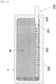
Classifications
-
- B—PERFORMING OPERATIONS; TRANSPORTING
- B67—OPENING, CLOSING OR CLEANING BOTTLES, JARS OR SIMILAR CONTAINERS; LIQUID HANDLING
- B67D—DISPENSING, DELIVERING OR TRANSFERRING LIQUIDS, NOT OTHERWISE PROVIDED FOR
- B67D7/00—Apparatus or devices for transferring liquids from bulk storage containers or reservoirs into vehicles or into portable containers, e.g. for retail sale purposes
- B67D7/06—Details or accessories
- B67D7/80—Arrangements of heating or cooling devices for liquids to be transferred
- B67D7/82—Heating only
-
- B—PERFORMING OPERATIONS; TRANSPORTING
- B01—PHYSICAL OR CHEMICAL PROCESSES OR APPARATUS IN GENERAL
- B01J—CHEMICAL OR PHYSICAL PROCESSES, e.g. CATALYSIS OR COLLOID CHEMISTRY; THEIR RELEVANT APPARATUS
- B01J4/00—Feed or outlet devices; Feed or outlet control devices
- B01J4/001—Feed or outlet devices as such, e.g. feeding tubes
-
- B—PERFORMING OPERATIONS; TRANSPORTING
- B01—PHYSICAL OR CHEMICAL PROCESSES OR APPARATUS IN GENERAL
- B01J—CHEMICAL OR PHYSICAL PROCESSES, e.g. CATALYSIS OR COLLOID CHEMISTRY; THEIR RELEVANT APPARATUS
- B01J6/00—Heat treatments such as Calcining; Fusing ; Pyrolysis
-
- F—MECHANICAL ENGINEERING; LIGHTING; HEATING; WEAPONS; BLASTING
- F28—HEAT EXCHANGE IN GENERAL
- F28D—HEAT-EXCHANGE APPARATUS, NOT PROVIDED FOR IN ANOTHER SUBCLASS, IN WHICH THE HEAT-EXCHANGE MEDIA DO NOT COME INTO DIRECT CONTACT
- F28D7/00—Heat-exchange apparatus having stationary tubular conduit assemblies for both heat-exchange media, the media being in contact with different sides of a conduit wall
- F28D7/10—Heat-exchange apparatus having stationary tubular conduit assemblies for both heat-exchange media, the media being in contact with different sides of a conduit wall the conduits being arranged one within the other, e.g. concentrically
- F28D7/12—Heat-exchange apparatus having stationary tubular conduit assemblies for both heat-exchange media, the media being in contact with different sides of a conduit wall the conduits being arranged one within the other, e.g. concentrically the surrounding tube being closed at one end, e.g. return type
-
- F—MECHANICAL ENGINEERING; LIGHTING; HEATING; WEAPONS; BLASTING
- F28—HEAT EXCHANGE IN GENERAL
- F28D—HEAT-EXCHANGE APPARATUS, NOT PROVIDED FOR IN ANOTHER SUBCLASS, IN WHICH THE HEAT-EXCHANGE MEDIA DO NOT COME INTO DIRECT CONTACT
- F28D21/00—Heat-exchange apparatus not covered by any of the groups F28D1/00 - F28D20/00
- F28D2021/0019—Other heat exchangers for particular applications; Heat exchange systems not otherwise provided for
- F28D2021/0042—Other heat exchangers for particular applications; Heat exchange systems not otherwise provided for for foodstuffs
Definitions
- the present invention relates to a melting device and a double pipe for discharging a melt of a substance into a tank to melt the substance stored in the tank; and a method for melting a substance using the melting device.
- fats and oils that are solid at ordinary temperature are transported by ship.
- a fat or oil in a liquid state is placed into a tank at the point of departure (the country of origin of the fat or oil), and the tank is loaded onto a ship.
- the destination the country of import of the fat or oil
- the fat or oil that has solidified into a solid state in the tank during transportation is melted.
- Patent Literature (PTL) 1 discloses a technique that uses a heat exchanger to melt a substance solidified in a flexible tank during transportation.
- the heat exchanger 200 shown in Figs. 14 to 16 is a schematic representation of the heat exchanger disclosed in PTL 1.
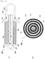
- the heat exchanger of PTL 1 (heat exchanger 200 shown in Figs. 14 to 16 ) is configured such that a second pipe 203 is disposed inside the first pipe 202; a third pipe 206 is disposed inside the second pipe 203; a fourth pipe 207 is disposed inside the third pipe 206; and a suction port 201 for suctioning a substance M in tank T ( Figs. 15 and 16 ) is formed by a gap between the first pipe 202 and the second pipe 203.
- a plurality of discharge ports 205 for discharging heated substance Ma into tank T are formed on the peripheral wall of the second pipe 203.
- Hot water P is allowed to flow inside the third pipe 206 and the fourth pipe 207 (specifically, hot water P is allowed to flow from the space outside the fourth pipe 207 in the third pipe 206 to the inside of the fourth pipe 207).
- the heat exchanger 200 When a fat or oil is transported, the heat exchanger 200 is disposed in the flexible tank T at the point of departure. After this, the flexible tank T is filled with a liquid substance M.
- a centrifugal force pump is driven to suction the substance M in the tank T into the heat exchanger 200 from the suction port 201; heat-exchange the substance M with hot water P in the heat exchanger 200; and also discharge the substance Ma heated by the heat exchange into the tank T from the discharge port 205 in order to melt the substance M in the tank T, which has solidified during transportation ( Fig. 15 ).
- the heated substance Ma circulates in the tank T and is heat-exchanged with an unmelted substance M, thereby causing the substance M in the tank T to melt.
- a general flexible tank T comprises a valve whose dimensions are specified by a standard ( FIGs. 10 and 11 described below show a valve 50 attached to a general flexible tank T). Any pipe that can be inserted into the hole of this valve can be easily attached to the flexible tank (i.e., the pipe can be attached to the tank by easy operation of inserting the pipe into the hole of the valve to fix the pipe to the valve etc.).
- Patent Literature (PTL) 1 heat exchanger 200 shown in Figs. 14 to 16
- PTL Patent Literature 1
- the diameter of the second pipe 203 must be enlarged in order to allow the desired amount of the melt to flow inside the second pipe 203, and be discharged from the discharge port 205.
- a situation may arise in which the heat exchanger 200 cannot be inserted into the hole of the valve attached to the flexible tank T.
- An object of the present invention is to provide a melting device for discharging a melt of a substance into a tank to melt the substance stored in the tank, the melting device being capable of discharging a desired amount of the melt into the tank, while reducing the diameter of a discharge pipe for discharging the melt of the substance; and to provide a method for melting the substance stored in the tank by using the melting device.
- Another object of the present invention is to provide a double pipe for discharging a melt of a substance into a tank to melt the substance stored in the tank, the double pipe being capable of discharging a desired amount of the melt into the tank while keeping the diameter of the pipe for discharging the melt small.
- the present invention includes the subject matter listed in the following items.
- the entirety of the inside of the discharge pipe is used as a flow path for the melt, whereby the desired amount of the melt can be discharged from the discharge pipe while the diameter of the discharge pipe is kept small.
- the entirety of the inside of the inner pipe is used as a flow path for the melt of the substance, whereby the desired amount of the melt can be discharged into the tank while the diameter of the inner pipe for discharging the melt is kept small.
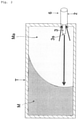
- Fig. 1 is a schematic diagram of the melting device 1 according to an embodiment of the present invention.
- Fig. 2 is a schematic diagram showing the internal state of a tank T to which the melting device 1 of this embodiment is applied.
- the melting device 1 discharges a melt Ma of substance M into a tank T in order to melt the substance M stored in the tank T.
- the tank T is a flexible tank made of vinyl, and is filled with a substance M that is solid at ordinary temperature.
- the substance M is, for example, wax, or fat/oil (an ester of glycerin and fatty acid).
- the melting device 1 comprises a suction pipe 2 and a discharge pipe 3, which are attached to the wall of the tank T, a circulation flow path 4, which is disposed outside the tank T, and a pump 5, which is disposed at a midway position of the circulation flow path 4.
- the inside of the tank T communicates with the inside of one end 4a of the circulation flow path 4 through the inside of the suction pipe 2, whereas the inside of the tank T communicates with the inside of the other end 4b of the circulation flow path 4 through the inside of the inner pipe 3.
- the melt Ma of substance M that is present in the tank T can be suctioned into the suction pipe 2, circulated through the circulation flow path 4, supplied into the discharge pipe 3, and discharged into the tank T through the opening 3s at the tip of the discharge pipe 3.
- the heat of the melt Ma that is discharged into the tank T the unmelted substance M that is present in the tank T is melted, and becomes a melt Ma.
- the melt Ma is suctioned into the suction pipe 2 and discharged into the tank T, whereby the unmelted substance M that is present in the tank T melts into a melt Ma.
- the configuration of the melting device 1 is specifically described below.
- Fig. 3 is a schematic diagram showing a double pipe 6 according to the present embodiment.
- Fig. 3(a) is a diagrammatic perspective view
- Fig. 3(b) is a cross-sectional view.
- the melting device 1 of this embodiment is provided with a double pipe 6 comprising an outer pipe that constitutes a suction pipe 2 and an inner pipe that constitutes a discharge pipe 3 (hereinafter the reference numeral "2" for the suction pipe is used as a reference numeral for the outer pipe, and the reference numeral "3" for the discharge pipe is used as a reference numeral for the inner pipe).
- the double pipe 6 is one in which an inner pipe 3 (discharge pipe) passes through the inside of an outer pipe 2.
- the inside of the tank T communicates with the inside of one end 4a of the circulation flow path 4 through the space K outside the inner pipe 3 (discharge pipe) in the outer pipe 2 (suction pipe).
- the inside of the tank T communicates with the inside of the other end 4b of the circulation flow path 4 through the inside of the inner pipe 3 (discharge pipe) ( Fig. 1 ).
- a pump 5 provided in the circulation flow path 2 is driven, whereby the melt Ma of substance M that is present in the tank T can be suctioned into the space K, circulated through the circulation flow path 4, and discharged from the inside of the inner pipe 3 (discharge pipe) to the inside of the pipe T.
- the space K and the entirety of the inside of the inner pipe 3 (discharge pipe) are used as a flow path for the melt Ma.
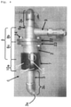
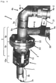
- Figs. 4 to 6 are images showing an example of the double pipe 6 described above.
- the double pipe 6 shown in Figs. 4 to 6 is formed of an outer pipe 2, which is a suction pipe, an inner pipe 3, which is a discharge pipe, and a coupling 7.
- the outer pipe 2 and inner pipe 3 are made of metal such as stainless steel or resin (in the examples shown in the figures, the outer pipe 2 and inner pipe 3 are made of stainless steel (SUS304 JIS5K)).
- the outer pipe 2 (suction pipe) comprises an outer pipe body 8 and a base pipe 9.
- the base pipe 9 extends from the base end side 8b of the outer pipe body 8, and the direction of extension of the base pipe 9 is inclined to the extension direction of the outer pipe body 8.
- the direction of extension of the base pipe 9 is perpendicular to the direction of extension of the outer pipe body 8.
- the direction does not have to be perpendicular.
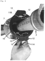
- Fig. 7 and Fig. 8 are enlarged images of the coupling 7.
- the coupling 7 has a cylindrical coupling body 10 and two levers 11A and 11B that are tiltably attached to the coupling body 10.
- the coupling body 10 has a cylindrical shape with openings at both ends, and is formed from resin.
- the base end side of the coupling body 10 is covered with the tip side of the outer pipe 2 (tip side 8c of the outer pipe body 8) ( Fig. 4 to Fig. 6 ).
- the tip side 8b of the outer pipe body 8 is inserted into the inside of the base end side of the coupling body 10, and the screw formed on the inner surface of the coupling body 10 is screwed to the screw formed on the outer surface of the outer pipe body 8, thereby fixing the base end side of the coupling body 10 to the tip side 8b of the outer pipe body 8.
- the coupling body 10 may also be fixed to the outer pipe body 8 by any known means other than screws.
- the coupling body 10 may be made of rubber or a metal.
- Two pairs of projections 12, 12 are provided on the outer surface of the coupling body 10 ( Fig. 8 ).
- the two sets of projections 12, 12 are provided at relative positions in the radial direction, and a shaft member 13 is attached to each set of projections 12, 12.
- the shaft member 13 extends from one projection 12 to the other projection 12.
- a through-hole 10b ( Fig. 8 ) is formed between the projections 12, 12.
- This through-hole 10b extends radially inwardly from the outer surface of the coupling body 10 and opens on the inner surface of the coupling body 10, and one end side 11a of the lever is inserted inside the through-hole 10b.
- the inner pipe 3 (discharge pipe) passes through the inside of the outer pipe body 8 and the inside of the coupling body 10.
- the inside of the base pipe 9 communicates with the space outside the inner pipe 3 (equivalent to the space K shown in Fig. 3 ) in the outer pipe body 8 and the coupling body 10.
- the base end side 3a of the inner pipe 3 extends from the base end position of the outer pipe 2 (specifically, the position of the base end 8a of the outer pipe body 8).
- the gap between the outer pipe body 8 and the inner pipe 3 is closed by an annular member 14 (the outer peripheral edge of the annular member 14 is welded to the outer pipe body 8, and the inner peripheral edge of the annular member 14 is welded to the inner pipe 3).
- the tip side 3b of the inner pipe 3 ( Fig. 4 to Fig. 6 ) extends from the tip of the coupling body 10.
- the double pipe 6 disclosed above is a combination of two components (first and second components).
- the first member comprises a base end side of the outer pipe 2 (specifically, a base end side 8b of the outer pipe body 8 and the base end pipe 9), the annular member 14 ( Fig. 6 ), and the inner pipe 3.
- the second member comprises a tip side of the outer pipe 2 (specifically a tip side 8c of the outer pipe body 8) and a coupling 7.
- a first flange 22 is provided on the base end side 8b of the outer pipe body 8, and a second flange 23 is provided on the tip side 8c of the outer pipe body 8. These flanges 22 and 23 project radially outwardly of the outer pipe body 8, and extend in the circumferential direction of the outer pipe body 8.
- the first flange 22 and the second flange 23 are butt-jointed and bolted together with bolts 24 to combine the first member and the second member, thus forming a double pipe 6.
- the double pipe 6 can be disassembled into the first member and the second member by unfastening the bolts 24.
- the circulation flow path 4 ( Fig. 1 ) is formed by connecting, for example, flexible metal hoses (diameter: 32A) made of SUS304. To connect the above flexible metal hoses to each other, for example, connection fittings specified in JIS 10K can be used.
- the pipe that constitutes one end 4a of the circulation flow path 4 (Fig. 1 , Fig. 5 , Fig. 6 ) is connected to the base end side (more specifically, the base pipe 9) of the outer pipe 2 (suction pipe), so that the "inside of the tank T" and the “inside of one end 4a of the circulation flow path 4" communicate with each other through the "inside of the outer pipe 2" (the "inside of the outer pipe 2" corresponds to the "inside of the base pipe 9" and "the space outside the inner pipe 3 in the outer pipe body 8 and the coupling body 10").
- the pipe that constitutes the other end 4b of the circulation flow path 4 ( Fig.
- a first on-off valve 30 is provided on the pipe that constitutes one end 4a of the circulation flow path 4.
- a second on-off valve 31 is provided on the pipe that constitutes the other end 4b of the circulation flow path 4.
- the other end 4b of the circulation flow path 4 is composed of an L-shaped joint pipe 4b-1 and a straight pipe 4b-2.
- a second on-off valve 31 is provided in the straight pipe 4b-2.
- the base end of the inner pipe 3 is connected to one end of the coupling pipe 4b-1 by a screw, and the other end of the coupling pipe 4b-1 is connected to one end of the straight pipe 4b-2 by a screw.
- the coupling pipe 4b-1 may be omitted, and the base end of the inner pipe 3 may be connected by a screw or the like to the straight pipe 4b-2 to which the second on-off valve 31 is attached.
- the base pipe 9 may be omitted from the outer pipe 2, and the pipe that constitutes one end 4a of the circulation flow path 4 may be connected to the base end side 8b of the outer pipe body 8.
- the "inside of the tank T" and the “inside of one end 4a of the circulation flow path 4" communicate with each other through the "space outside the inner pipe 3 in the outer pipe body 8 and the coupling body 10."
- the first member described above comprises the base end side 8b of the outer pipe body 8 (the base end side of the outer pipe 2), an annular member 14 ( Fig. 6 ), and the inner pipe 3.
- a pump capable of reversing the fluid pumping direction is provided as a pump 5 disposed at a midway position of the circulation flow path 4 ( Fig. 1 ).
- This pump can be, for example, a rotary pump.
- the circulation flow path 4 ( Fig. 1 ) is further provided with a thermometer 40, a pressure gauge 41, a sight glass 42, a primary-side hopper 43A, and a secondary-side hopper 43B, in addition to the pump 5 described above.
- the pressure gauge 41 measures the pressure of the melt Ma of substance M that is pumped through the circulating flow path 4 by the pump 5.
- the thermometer 40 measures the temperature of the melt Ma that flows through the circulation flow path 4.
- the sight glass 42 is a tubular body with a window made of glass, through which the state of the melt Ma flowing in the circulation flow path 4 can be checked.
- the primary-side hopper 43A and the secondary-side hopper 43B are capable of storing the melt Ma of the substance M.
- the primary-side hopper 43A is connected to the primary side of the pump 5 in the circulation flow path 4 via the primary-side third on-off valve 44A.
- the secondary-side hopper 43B is connected to the secondary side of the pump 5 in the circulation flow path 4 via the secondary-side third on-off valve 44B.
- the melt Ma stored in the primary-side hopper 43A can be circulated through the circulation flow path 4 and supplied to the inside of the inner pipe 3 (discharge opening). Furthermore, if the secondary-side third on-off valve 44B is opened, a part of the melt Ma flowing through the circulation flow path 4 can flow into the secondary-side hopper 43B, so that the state of the melt Ma can be observed.
- the melt Ma in the tank T can be suctioned into the outer pipe 2 (suction pipe), circulated through the circulation flow path 4, supplied to the inner pipe 3 (discharge pipe), and discharged from the opening 3s of the inner pipe 3 into the tank T. Furthermore, if the third on-off valves 44A, 44B are opened, a part of the melt Ma flowing in the circulation flow path 4 can flow into the hoppers 43A, 43B, so that the condition of the melt Ma can be observed.
- the melt Ma in the circulation flow path 4 can be allowed to flow in the opposite direction.
- the melt Ma in the tank T can be suctioned into the inner pipe 3, circulated through the circulation flow path 4, and discharged into the tank T from the space K outside the inner pipe 3 in the outer pipe 2.
- step S101 in Fig. 9 the step of taking out a part of the substance M that has solidified in the tank T is preformed.
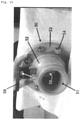
- the tank T is a general flexible tank and the valve 50 shown in Figs. 10 and 11 is attached to the wall of the tank T, a part of the substance M that has solidified in the tank T is taken out from the hole 51 of the valve 50.
- the structure of the valve 50 is described below.
- the valve 50 comprises a cylinder 52 and an annular member that is not shown in the figure.
- An annular flange 53 is provided at the base end of the cylinder 52.
- the flange 53 projects radially outwardly of the cylinder 52 and extends in the circumferential direction of the cylinder 52.
- the annular member which is not shown in the figure, has an outer diameter that is equal to the outer diameter of the flange 53, and an inner diameter that is equal to the inner diameter of the cylinder 52.
- a through-hole (not shown) is formed in the wall of the tank T. The diameter of the through-hole is substantially equal to the inner diameter of the cylinder 52 and the annular member.
- the flange 53 is fasten to the annular member by bolts 54 (the bolts 54 penetrate the wall of the tank T) while the space inside the cylinder 52, the through-hole formed in the wall of the tank T, and the space inside the annular member communicate with each other and the wall of the tank T is interposed between the flange 53 and the annular member (the bolts 54 penetrate the wall of the tank T).
- the "hole 51 of the valve” described above is formed by connection of the "space inside the cylinder 52," the "through-hole formed in the wall of the tank T,” and the "space inside the annular member.”
- the cylinder 52 is provided with a ball 56 and a lever 57 that is fastened to the ball 56.
- the ball 56 is a hollow sphere and is placed inside the cylinder 52.
- Two through-holes 58, 58 are formed in the wall of the ball 56 (hollow sphere) (one through-hole 58 is shown in Fig. 10 ).
- the two through-holes 58, 58 oppose each other in the radial direction of the ball 56, and the diameters of the through-holes 58, 58 are substantially equal to the inner diameter of the cylinder 52.
- a lever 57 extends from the ball 56 radially outwardly of the cylinder 52 and penetrates the cylinder 52, and a handle 59 is provided at the tip of the lever 57 extending from the cylinder 52.
- the ball 56 can be rotated in the cylinder 52 to dispose the two through-holes 58, 58 on the axis of the cylinder 52.
- the hole 51 of the valve 50 can be opened as shown in Fig. 10 .
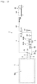
- the position of the through-holes 58, 58 can be changed to close the hole 51 of the valve 50 by the wall of the ball 56 as shown in Fig. 11 .
- the first operation in step S101 is to open the hole 51 of the valve 50 by rotating the lever 57 (to make the valve 50 in the state shown in Fig. 10 ).
- a hand drill (not shown) is inserted into the tank T through the hole 51 of the valve 50.
- the hand drill is withdrawn from the hole 51 of the valve 50, whereby the material M scraped by the hand drill is taken out of the tank T.
- the method of taking out the substance M from the tank T in step S101 is not limited to the method described above. For example, if the tank T is provided with a removable lid, the lid may be removed and the substance M in the tank T may be taken out.
- step S101 the melt Ma obtained by melting the substance M taken out from the tank T is stored in the primary-side hopper 43A (step S102 in Fig. 9 ).
- step S102 for example, the substance M taken out from the tank T is melted with a heater (a stove etc.), and the melt Ma obtained from this melt is fed into the primary-side hopper 43A.
- a metal pipe may be wound around the outer peripheral surface of the primary-side hopper 43A to melt the substance M in the primary-side hopper 43A.
- steam or hot water is allowed to flow into the metal pipe with the substance M taken out from the tank T being placed in the primary-side hopper 43A.
- the heat of the steam or hot water melts the substance M placed into the primary-side hopper 43A, and the melt Ma is stored in the hopper 43A.
- step S102 the suction pipe 2 and the discharge pipe 3 are connected to the tank T, and the pump 5 is driven in forward rotation with the secondary-side on-off valve 31 and the primary-side third on-off valve 44A ( Fig. 1 ) being opened and the primary-side on-off valve 30 being closed (step S103).
- This allows the melt Ma stored in the primary-side hopper 43A to circulate through the circulation flow channel 4 and be supplied to the inside of the discharge pipe 3 and discharged from the opening 3s of the discharge pipe 3 to the inside of the tank T.
- the heat of the discharged melt Ma melts the substance M in the vicinity of the discharge pipe 3, within the substance M that is present in the tank T, whereby the substance becomes the melt Ma.
- suction pipe 2 and the discharge pipe 3 are formed of a dual pipe 6 shown in Figs. 4 to 6 , and the valve 50 shown in Figs. 10 and 11 is attached to the wall of the tank T, the suction pipe 2 and the discharge pipe 3 are attached to the wall of the tank T in step S103 by attaching the double pipe 6 to the valve 50.
- the step of attaching the double pipe 6 to the valve 50 is explained below.
- the lever 11 is tilted to reduce the degree to which one end side 11a of the lever 11 projects to the inside of the coupling body 10.
- the hole 51 of the valve 50 is made open (state shown in Fig. 10 ) by rotating the lever 57.
- the inner pipe 3 ( Figs. 4 to 8 ) is inserted into the hole 51 of the valve 50 to make the tip portion of the inner pipe 3 project to the inside of the tank T ( Fig. 1 , Fig. 2 ), and the tip side 10a of the coupling body 10 ( Fig. 4 to Fig. 6 ) is covered with the cylinder 52 of the valve 50 ( Fig. 10 ).
- This allows the inside of the outer pipe 2 (suction pipe) and the inside of the inner pipe 3 (discharge pipe) to individually communicate with the inside of the tank T. If the material M in the tank T is scraped off in step S101, the tip portion of the inner pipe 3 is inserted into the hole of the material M created by this scraping.
- step S104 the pump 5 is driven forward with the first on-off valve 30 and the second on-off valve 31 being open, whereby the melt Ma that is present in the tank T can be suctioned into the suction pipe 2, circulated through the circulation flow path 4, supplied to the inside of the discharge pipe 3, and discharged from the opening 3s of the discharge pipe 3 into the tank T (Step S104).
- the substance M that is present in an unmelted state in the tank T melts due to heat of the melt Ma discharged into the tank T. More specifically, in step S104, the melt Ma previously discharged from the discharge pipe 3 and the melt Ma melted by the heat of the melt Ma are repeatedly suctioned into the suction pipe 2 and discharged from the discharge pipe 3.
- the amount of the melt Ma discharged from the discharge pipe 3 i.e., the amount of the melt Ma suctioned from the suction pipe 2 increases with the lapse of time, and the range in which the substance M is melted in the tank T gradually expands from the vicinity of the discharge pipe 3 ( Fig. 2 ).
- the drive of the pump 5 is temporarily stopped to store the hot melt Ma in the primary-side hopper 43A, for example.
- the pump 5 is driven forward with the first on-off valve 30 being closed and the second on-off valve 31 and the primary-side third on-off valve 44A being open. Since the high-temperature melt Ma can be supplied to the inside of the tank T in this way, melting of the substance M can be resumed (that is, the melt Ma stored in the hopper 43A can be used as the priming oil for resuming the melting.)
- the entirety of the inside of the discharge pipe 3 (inner pipe) that discharges the melt Ma of the substance M is used as a flow path for the melt Ma. Therefore, it is possible to discharge the desired amount of the melt from the discharge pipe 3 (inner pipe) while keeping the diameter of the discharge pipe 3 (inner pipe) small. Since the diameter of the discharge pipe 3 (inner pipe) can be kept small, the hole of the existing valve in the tank T can be used as a hole for inserting the discharge pipe 3 (inner pipe). Unlike in conventional technology, it is unnecessary to remove the existing valve from the tank T, install a custom-made valve with a larger hole in the tank T instead, and insert the discharge pipe into the hole of the valve.
- the discharge pipe is a pipe inserted into a hole in the wall of the tank T and directly or indirectly attached to the wall of the tank T, while it is connected by screws or welding, etc., to a pipe that constitutes an end of the circulation flow path 4 (a coupling pipe, a pipe in which a valve is attached, etc.) and is used to discharge the melt Ma flowing through the circulation flow path 4 into the interior of the tank T.
- a coupling pipe a pipe in which a valve is attached, etc.
- the discharge pipe 3 (inner pipe) is integrated with the suction pipe 2 (outer pipe), and the suction pipe 2 (outer pipe) is attached to the valve 50 with the discharge pipe 3 (inner pipe) being inserted into the hole of the valve 50 provided in the wall of the tank T, whereby the suction pipe 2 (outer pipe) is directly attached to the wall of the tank T and the discharge pipe 3 (inner pipe) is indirectly attached to the wall of the tank T through the suction pipe 2 (outer pipe).
- the melting device 1 of this embodiment if the length of the discharge pipe 3 (inner pipe 3) extending into the tank T is shortened, the hole in the substance M, into which the tip portion of the discharge pipe 3 (inner pipe 3) is inserted, does not need to be lengthened. Therefore, the time and effort required to make holes in step S101 of Fig. 9 can be reduced. Furthermore, according to this embodiment, a melt Ma to be stored in the primary-side hopper 43A is obtained by melting the substance M obtained by making the holes, and the melt Ma is supplied to the tank T and becomes the priming oil that triggers the melting. In this way, the substance M obtained by making holes is effectively utilized and not wasted.
- the melting device 1 of this embodiment if clogging occurs in the circulation flow path 4, suction pipe 2, or discharge pipe 3, the clogging can be removed by driving the rotary pump 5 in reverse, and allowing the melt Ma to flow in the opposite direction by pumping. Further, by connecting hoppers to the primary and secondary sides of the pump 5, one of these hoppers can be used to store the melt Ma as priming oil, whereas the other hopper can be used to sample the melt Ma flowing in the circulation flow path 4.
- a rotary pump 5 capable of driving in reverse is used, so that the high-temperature melt Ma stored in the secondary-side hopper 43B can be discharged from the inner pipe 3 (suction pipe 2), and the substance M in the tank T can be melted by the heat of the discharged melt Ma. Since this is possible, a metal pipe may be wound not only around the outer circumference of the primary-side hopper 43A, but also around the outer circumference of the secondary-side hopper 43B. With this configuration, the substance M fed into the secondary-side hopper 43B can be melted and the melt Ma can be stored in the secondary-side hopper 43B by allowing steam or hot water to flow inside the metal pipe.
- the circulation flow path 4 can be heated by the heat of the steam or hot water by allowing steam or hot water to flow inside of the metal pipe. This can prevent freezing of the melt Ma that flows through the circulation flow path 4.
- the outer diameter of the inner pipe 3 ( Figs. 4 to 8 ) is made smaller than the inner diameter of the cylinder 52 ( Figs. 10 and 11 ), and the inner diameter of the coupling body 10 ( Figs. 4 to 8 ) is made substantially equal to the outer diameter of the cylinder 52 ( Figs. 10 and 11 ) to thereby attach the valve 50 to the tank.
- the double pipe according to this embodiment can be disassembled into two parts (first and second parts). Therefore, when a problem such as clogging occurs in the double pipe 6, operations to solve the problem can be easily performed.
- the melting device 1 of the present invention may be provided with heating means 70 disposed inside the tank T, as shown in Fig. 12(a) .
- the heating means 70 is a tubular body in which hot water or steam flows, and the tubular body is preferably a flexible pipe.
- the flexible pipe can be a winding flexible pipe for water supply (RFL25) manufactured by Liviluck Co., Ltd.
- the heating means 70 is a heater pad provided with a conductor that generates heat through electrical resistance.
- the heating means 70 tubular body or heater pad
- the heat emitted by the heating means 70 heats the substance M in the tank T to melt the substance M
- the resulting high-temperature melt is suctioned from the suction pipe 2 and discharged from the discharge pipe 3 into the tank T, whereby the material M that has coagulated in the tank T can be melted early.
- the heating means 70 When the heating means 70 is a tubular body with hot water flowing inside, the hot water in the hot water tank T is supplied to the tubular body (heating means 70) through a first flow path by the pressure of the pump 5, and the hot water supplied to the tubular body is returned to the hot water tank through a second flow path.
- the heating means 70 When the heating means 70 is a tubular body with steam flowing inside, the steam generated by a steam-water mixer is supplied to the tubular body (heating means 70) through the first flow path, and the steam supplied to the tubular body is discharged through the second flow path.
- the heating means 70 may be buried in the wall of the tank T.
- the heating means 70 may be disposed outside the tank T and abut the wall of the tank T. With such a configuration, it is unnecessary to dispose the heating means 70 inside of the tank T; accordingly, the tank T can be prevented from being torn by contact with the heating means 70.
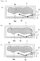
- the direction of the discharge pipe 3 is adjusted so that the melt Ma discharged from the inside of the discharge pipe 3 to the inside of the tank T is directed to the position of the heating means 70, as shown in Figs. 12(a), 12(b), and 12(c) .
- the melt Ma discharged from the discharge pipe 3 can be heated by the heating means 70, so that the high-temperature melt Ma can be circulated in the tank T. This allows the substance M in the tank T to be melted earlier.
- the melt Ma discharged from the opening 3s of the discharge pipe 3 to the inside of the tank T can be directed to the position of the heating means 70 by bending the tip portion 3c of the discharge pipe 3 as shown in the figures.
- the tank T does not comprise any cooling means to cool the substance M stored inside.
- two hoppers 43A and 43B are not necessarily provided, and only one of the hoppers 43A and 43B may be provided. Alternatively, the hoppers 43 may be omitted. Even in this case, if the heating means 70 is provided in the melting device 1, the heat emitted by the heating means 70 can melt the substance M coagulated in the tank T, and the melt Ma can be suctioned from the suction pipe 2 and discharged from the discharge pipe 3 to thereby melt the substance M in the tank T. Alternatively, the substance M taken out from the tank T can be melted using a heater (e.g., a stove), and the melt Ma can be fed into the tank T.
- a heater e.g., a stove
- the melt Ma fed into the tank T can be suctioned from the suction pipe 2 and discharged from the discharge pipe 3, whereby the melt Ma can be used as priming oil that triggers the melting of the substance.
- a melt of the substance to be prepared at the destination i.e., a melt of the substance that was not stored in the tank T during transportation
- the melt of the substance fed into the tank T is suctioned from the suction pipe 2 and discharged from the discharge pipe 3, so that the melt Ma of the substance fed into the tank T can be used as the priming oil that triggers the melting of the substance.
- the melt of the substance fed into the tank T may be a melt of the same kind of substance as the one stored in the tank T during transportation, or may be a melt of a substance of a kind different from the one stored in the tank T.
- the melting device 1 may also be provided with a melt heating means for heating the melt Ma flowing through the circulation flow path 4.
- the melt heating means is a heat exchanger that exchanges heat between steam or hot water and the melt Ma.
- the melt heating means is a heater comprising a conductor that generates heat through electrical resistance.
- the melt heating means (heater) is disposed so that the conductor is in contact with the pipe that constitutes the circulating flow path 4, and the heat of the conductor is thereby transferred to the melt Ma flowing in the circulating flow path 4.
- the discharge pipe 3 and the suction pipe 2 do not necessarily need to be formed of a double pipe 6, and the discharge pipe 3 and the suction pipe 2 may be separately and independently attached to the wall of the tank T. If a double pipe 6 is used, both the discharge pipe 3 and the suction pipe 2 can be attached by attaching the double pipe 6 to the tank T. This reduces the time and effort required for attachment. Also, by using the double pipe 6, the discharge pipe 3 and the suction pipe 2 can be coaxially arranged, so that the melt Ma discharged from the discharge pipe 3 can be reliably suctioned into the suction pipe 2. This allows the melt Ma to continue to be discharged from the discharge pipe 3, so that the melting of the substance M can continue to occur.
- a pump whose fluid pumping direction is restricted to one direction may be provided in the circulating flow path 4 in place of the pump 5 capable of pumping a fluid in a reverse direction as described above. Even in this case, by driving the pump, the melt Ma that is present in the tank T can be suctioned into the suction pipe 2, supplied to the inside of the discharge pipe 3 through the circulation flow path 4, and discharged into the tank T through the opening 3s of the discharge pipe 3, whereby the substance M in the tank T can be melted.
- a rotary pump or a centrifugal pump can be used as the "pump whose fluid pumping direction is restricted to one direction."
- the centrifugal pump for example, an LDP-type line pump (50LPD62.2A) manufactured by Ebara Corporation can be used.
- the discharge pipe 3 may be composed of a mixing ejector comprising a nozzle and a diffuser.
- the nozzle is configured to inject the melt Ma, which is sent through the circulation flow path 4, into the diffuser.
- the diffuser is configured to suction the melt Ma that is present in the tank T by a pressure decrease due to ejection of the melt Ma from the nozzle, and injects the suctioned melt Ma into the tank T together with the melt Ma injected from the nozzle.
- the suctioned melt Ma is injected into the tank T together with the melt Ma ejected from the nozzle.
- a large amount of the melt Ma that is present around the discharge pipe 3 can be suctioned from the suction pipe 2 without requiring power (electric power, etc.) to increase the circulation amount of the melt Ma in the circulation flow path 4, thereby increasing the energy efficiency of the melting device 1 (that is, the amount of material melted per hour can be increased while keeping the energy required to drive the melting device 1 small).
- a Mixing Eductor 3MP manufactured by Yamamoto Sangyo Co., Ltd. can be used as the mixing ejector described above.
- a spray nozzle through which the melt Ma is sprayed may be attached to the tip of the discharge pipe 3.
- the use of the spray nozzles described above can accelerate the stirring of the melt Ma in the tank T, thus speeding up the melting of the substance M.
- a TURBO DISC manufactured by Nippon Howard Corporation can be used as the spray nozzle.
- the melting device 1 of the present invention may also comprise a gas supply means capable of supplying gas to the circulation flow path 4.
- a gas supply means capable of supplying gas to the circulation flow path 4.
- air bubbles are ejected from the discharge pipe 3 into the tank T together with the melt Ma, thereby promoting stirring of the melt Ma in the tank T.
- a gas-liquid shear-type microbubble generator (BL12AA-12-D4, direct operation-type) manufactured by Nitta-Moore Corporation can be used. If the flexible tank T is used as the tank T, the gas discharged into the tank T can be discharged from a safety valve provided in the flexible tank T.
- the substance M that can be melted by the melting device 1 of the present invention is not limited to waxes and fats.
- the objects to be melted by the melting device 1 of the present invention can be various substances that can be melted by the heat of the melt Ma.
- the tank T for storing the substance M to be melted is not limited to a flexible tank made of vinyl; a tank T made of a material other than vinyl may be used.
- the tank T may be an ISO (International Organization for Standardization) tank made of metal.
- the suction pipe 2 and discharge pipe 3 are attached to the wall of the ISO tank by known means.
- a discharge channel 80 for discharging the melt Ma flowing through the circulating flow path 4 may be connected to the circulating flow path 4.
- a fourth on-off valve 81 is provided in the discharge channel 80. By opening the on-off valve 81, some of the melt Ma flowing through the circulating flow path 4 into the discharge channel 80 can be allowed to flow into the discharge channel 80.
- a fifth on-off valve 82 may be provided at a position of the circulation flow path 4 that is downstream of the connection point of the discharge flow path 80.
- the melt Ma flowing through the discharge channel 80 is fed into the tank 84 of the truck 83, and the melt Ma is transported by the truck 83.
- the present inventors conducted an experiment to compare the performance of the melting device of an Example of the present invention with that of the melting device of a Comparative Example. This experiment is described below.
- a flexible pipe (heating means 70) was inserted into a flexible tank T
- the tank T was filled with 110 kg of palm oil mid-melting point fraction (PMF: Palm Mid-Fraction). After this, the tank T was allowed to stand in a room at 20°C for 3 days to solidify the oil in the tank T.
- a hand drill was then inserted into the tank T through a hole in the tank T. A part of the solidified oil was scraped off by the rotation of the hand drill, and a hole was made in the oil.
- a double pipe 6 was attached to the tank T so that the tip of the discharge pipe 3 could be placed in the hole, and a circulation flow path 4 was connected to the double pipe 6.
- the scraped oil was fed into the primary-side hopper 43A to melt the oil.
- hot water of 70°C to 80°C was started to flow through the inside of the flexible pipe (heating means 70) at a flow rate of 0.7 m 3 /h.
- the pump 5 was driven to discharge the melt Ma in the hopper 43A into the tank T.
- the second on-off valve 30 being closed and the third on-off valve 31 and 44A being open, the pump 5 was driven to discharge the melt Ma in the hopper 43A into the tank T.
- the first on-off valve 30 was opened in order to suction the melt Ma that was present in the tank T, and discharge the melt Ma into the tank T.
- the temperature of the melt Ma and the condition in the tank T were checked 4 hours and 5 hours after the start of allowing the water to flow into the flexible pipe (hereinafter referred to as the "water flow start time").
- the melting device of the Comparative Example is one in which the double pipe 6 and the circulation flow path 4 are omitted from the melting device of the Example. The following operations were performed to check the performance of the melting device of the Comparative Example.
- the tank T was filled with 110 kg of palm oil mid-fraction (PMF). After this, the tank T was left in a room of 20°C for 3 days to allow the oil in the tank T to solidify. Hot water of 70 to 80°C was started to flow into the flexible pipe at a flow rate of 0.7 m 3 /h. The temperature of the melt Ma and the condition in the tank T were checked 4 hours and 5 hours after the start of allowing the water to flow into the flexible pipe (hereinafter referred to as the "water flow start time").
- Table 1 shows the results confirmed by the above operations. Table 1 Elapsed time 4 hours 5 hours Temperature of melt Ma State in tank T Temperature of melt Ma State in tank T Melting device of Example 55.0°C No solid oil residue 65.0°C No solid oil residue Melting device of Comparative Example 31.0°C Solid oil residue observed 43.8°C Solid oil residue: 15.4 g
- the melting device of the present invention comprising the double pipe 6 and the circulation flow path 4 can melt fats and oils in the tank T early (in other words, it was confirmed that the fats and oils in the tank T can be melted early by suctioning the melt in the tank T and discharging the melt into the tank T).
Landscapes
- Chemical & Material Sciences (AREA)
- Engineering & Computer Science (AREA)
- Mechanical Engineering (AREA)
- Organic Chemistry (AREA)
- Chemical Kinetics & Catalysis (AREA)
- Physics & Mathematics (AREA)
- Thermal Sciences (AREA)
- General Engineering & Computer Science (AREA)
- Jet Pumps And Other Pumps (AREA)
- Feeding, Discharge, Calcimining, Fusing, And Gas-Generation Devices (AREA)
- Processing Of Solid Wastes (AREA)
- Loading And Unloading Of Fuel Tanks Or Ships (AREA)
Abstract
Description
- The present invention relates to a melting device and a double pipe for discharging a melt of a substance into a tank to melt the substance stored in the tank; and a method for melting a substance using the melting device.
- Conventionally, in international trade, fats and oils that are solid at ordinary temperature are transported by ship. During this transportation, a fat or oil in a liquid state is placed into a tank at the point of departure (the country of origin of the fat or oil), and the tank is loaded onto a ship. At the destination (the country of import of the fat or oil), the fat or oil that has solidified into a solid state in the tank during transportation is melted.
- Flexible tanks made of vinyl are used to transport such oils and fats. Patent Literature (PTL) 1 discloses a technique that uses a heat exchanger to melt a substance solidified in a flexible tank during transportation. (The
heat exchanger 200 shown inFigs. 14 to 16 is a schematic representation of the heat exchanger disclosed inPTL 1.) - The heat exchanger of PTL 1 (
heat exchanger 200 shown inFigs. 14 to 16 ) is configured such that asecond pipe 203 is disposed inside thefirst pipe 202; athird pipe 206 is disposed inside thesecond pipe 203; afourth pipe 207 is disposed inside thethird pipe 206; and asuction port 201 for suctioning a substance M in tank T (Figs. 15 and16 ) is formed by a gap between thefirst pipe 202 and thesecond pipe 203. A plurality ofdischarge ports 205 for discharging heated substance Ma into tank T are formed on the peripheral wall of thesecond pipe 203. Hot water P is allowed to flow inside thethird pipe 206 and the fourth pipe 207 (specifically, hot water P is allowed to flow from the space outside thefourth pipe 207 in thethird pipe 206 to the inside of the fourth pipe 207). - When a fat or oil is transported, the
heat exchanger 200 is disposed in the flexible tank T at the point of departure. After this, the flexible tank T is filled with a liquid substance M. When the tank T arrives at its destination, a centrifugal force pump is driven to suction the substance M in the tank T into theheat exchanger 200 from thesuction port 201; heat-exchange the substance M with hot water P in theheat exchanger 200; and also discharge the substance Ma heated by the heat exchange into the tank T from thedischarge port 205 in order to melt the substance M in the tank T, which has solidified during transportation (Fig. 15 ). As a result, the heated substance Ma circulates in the tank T and is heat-exchanged with an unmelted substance M, thereby causing the substance M in the tank T to melt. - PTL 1:
Japanese Patent No. 4639228 - A general flexible tank T comprises a valve whose dimensions are specified by a standard (
Figs. 10 and11 described below show avalve 50 attached to a general flexible tank T). Any pipe that can be inserted into the hole of this valve can be easily attached to the flexible tank (i.e., the pipe can be attached to the tank by easy operation of inserting the pipe into the hole of the valve to fix the pipe to the valve etc.). - In this regard, in the heat exchanger of Patent Literature (PTL) 1 (
heat exchanger 200 shown inFigs. 14 to 16 ), it is necessary to dispose athird pipe 206 and a fourth pipe 20 in thesecond pipe 203 comprising adischarge port 205 formed to exchange heat between the substance M and the hot water P. Accordingly, the diameter of thesecond pipe 203 must be enlarged in order to allow the desired amount of the melt to flow inside thesecond pipe 203, and be discharged from thedischarge port 205. As a result, a situation may arise in which theheat exchanger 200 cannot be inserted into the hole of the valve attached to the flexible tank T. In this case, in order to attach theheat exchanger 200 to the tank T, it is necessary, for example, to remove the existing valve from the tank T, attach a custom-made valve with a large hole to the tank T, and then insert theheat exchanger 200 into the hole of the valve. Such work may require a great deal of effort and cost. - The present invention was made in consideration of these matters. An object of the present invention is to provide a melting device for discharging a melt of a substance into a tank to melt the substance stored in the tank, the melting device being capable of discharging a desired amount of the melt into the tank, while reducing the diameter of a discharge pipe for discharging the melt of the substance; and to provide a method for melting the substance stored in the tank by using the melting device. Another object of the present invention is to provide a double pipe for discharging a melt of a substance into a tank to melt the substance stored in the tank, the double pipe being capable of discharging a desired amount of the melt into the tank while keeping the diameter of the pipe for discharging the melt small.
- In order to achieve the above object, the present invention includes the subject matter listed in the following items.
-
-
Item 1. A melting device for discharging a melt of a substance into a tank to melt the substance stored in the tank, the device comprising- a suction pipe attached to the wall of the tank;
- a discharge pipe attached to the wall of the tank;
- a circulation flow path disposed on the outside of the tank; and
- a hopper in which the melt of the substance is to be stored and that is connected to the circulation flow path via an on-off valve;
- the inside of the tank communicates with the inside of one end of the circulation flow path through the inside of the suction pipe;
- the inside of the tank communicates with the inside of the other end of the circulation flow path through the inside of the discharge pipe;
- a pump is disposed at a midway position of the circulation flow path; by driving the pump, the melt of the substance that is present in the tank is suctioned into the suction pipe, circulated through the circulation flow path, and discharged from inside the discharge pipe into the tank; and the entire inside of the discharge pipe is used as a flow path for the melt;
- the hopper comprises a primary-side hopper and a secondary-side hopper;
- the primary-side hopper is connected to the primary side of the pump in the circulation flow path via a primary-side on-off valve;
- the secondary-side hopper is connected to the secondary side of the pump in the circulation flow path via a secondary-side on-off valve; and
- the pump is capable of pumping a fluid in a reverse direction.
-
Item 2. The melting device according toItem 1, wherein- a metal pipe is wound around the outer circumference of the hopper; and
- steam or hot water is allowed to flow inside the metal pipe with the substance being placed in the hopper to thereby melt the substance in the hopper and store the melt in the hopper.
-
Item 3. A melting device for discharging a melt of a substance into a tank to melt the substance stored in the tank, the device comprising- a suction pipe attached to the wall of the tank;
- a discharge pipe attached to the wall of the tank; and
- a circulation flow path disposed outside the tank; wherein
- the inside of the tank communicates with the inside of one end of the circulation flow path through the inside of the suction pipe;
- the inside of the tank communicates with the inside of the other end of the circulation flow path through the inside of the discharge pipe;
- a pump is disposed at a midway position of the circulation flow path; by driving the pump, the melt of the substance that is present in the tank is suctioned into the suction pipe, circulated through the circulation flow path, and discharged from inside the discharge pipe into the tank; and the entire inside of the discharge pipe is used as a flow path for the melt;
- the discharge pipe comprising a mixing ejector comprising a nozzle and a diffuser;
- the nozzle ejecting the melt sent through the circulation flow path into the diffuser,
- the diffuser suctioning the melt present in the tank by a pressure decrease due to injection of the melt from the nozzle, and ejecting the suctioned melt into the tank together with the melt injected from the nozzle.
- Item 4. A method for melting a substance stored in a tank by using a melting device,
the melting device being configured to discharge a melt of a substance into the tank to melt the substance stored in the tank, the device comprising:- a suction pipe attached to the wall of the tank;
- a discharge pipe attached to the wall of the tank;
- a circulation flow path disposed outside the tank; and
- a hopper in which the melt of the substance is to be stored and that is connected to the circulation flow path via an on-off valve;
- wherein
- the inside of the tank communicates with the inside of one end of the circulation flow path through the inside of the suction pipe;
- the inside of the tank communicates with the inside of the other end of the circulation flow path through the inside of the discharge pipe;
- a pump is disposed at a midway position of the circulation flow path; by driving the pump, the melt of the substance that is present in the tank can be suctioned into the suction pipe, circulated through the circulation flow path, and discharged from inside the discharge pipe into the tank; and the entire inside of the discharge pipe is used as a flow path for the melt; and
- taking out a part of the substance solidified in the tank;
- storing in the hopper a melt obtained by melting the substance taken out from the tank;
- driving the pump with the on-off valve being open to supply the melt stored in the hopper into the discharge pipe through the circulation flow path and discharging the melt from the opening at the tip of the discharge pipe into the tank, whereby the substance present in the vicinity of the discharge pipe among the substance present in the tank is melted to form a melt; and
- driving the pump with the on-off valve being closed to suction the melt present in the tank into the suction pipe and supply the melt into the discharge pipe through the circulation flow path, and discharge the melt from the opening at the tip of the discharge pipe into the tank to thereby melt the substance present in an unmelted state in the tank.
-
Item 5. A double pipe for discharging a melt of a substance into a tank to melt the substance stored in the tank,
the double pipe comprising- an outer pipe;
- an inner pipe that passes inside the outer pipe; and
- a coupling;
- the inside of the tank communicates with the inside of one end of the circulation flow path through a space outside of the inner pipe in the outer pipe; the inside of the tank communicates with the inside of the other end of the circulation flow path through the inside of the inner pipe;
- a pump disposed at a midway position of the circulation flow path is driven, whereby the melt of the substance that is present in the tank can be suctioned into a space outside of the inner pipe in the outer pipe, circulated through the circulation flow path, and discharged from the inside of the inner pipe into the tank; the entire inside of the inner pipe is used as a flow path for the melt;
- the coupling comprises a cylindrical coupling body and a lever that is tiltably
attached to the coupling body; - the base end side of the coupling body is covered with the tip side of the outer pipe;
- by tilting the lever, the degree of projection of the lever to the inside of the coupling body can be reduced; and by tilting the lever in the opposite direction, the degree of projection of the lever to the inside the coupling body can be increased;
- the inner pipe passes through the inside of the outer pipe and the inside of the coupling body; the base end side of the inner pipe extends from the base end side position of the outer pipe; at the base end side of the outer pipe, the gap between the outer pipe and the inner pipe is blocked by an annular member; and
- the tip side of the inner pipe extends from the tip of the coupling body.
-
Item 6. The double pipe according toItem 5, which is a combination of a first member and a second member,- the first member comprising a base end side of the outer pipe, the annular member, and the inner pipe,
- the second member comprising the tip side of the outer pipe and the coupling,
- a first flange is provided on the base end side of the outer pipe, and a second flange is provided on the tip side of the outer pipe,
- the first flange and the second flange each project radially outwardly of the outer pipe and extend in the circumferential direction of the outer pipe,
- the first flange and the second flange are butt-jointed and bolted together to combine the first member and the second member, thus forming the double pipe; and by unfastening the bolts, the double pipe can be disassembled into the first member and the second member.
-
Item 7. A melting device for discharging a melt of a substance into a tank to melt the substance stored in the tank, the device comprising- a suction pipe attached to the wall of the tank;
- a discharge pipe attached to the wall of the tank; and
- a circulation flow path disposed outside the tank, wherein
- the inside of the tank communicates with the inside of one end of the circulation flow path through the inside of the suction pipe; and the inside of the tank communicates with the inside of the other end of the circulation flow path through the inside of the discharge pipe;
- a pump is provided at a midway position of the circulation flow path; by driving the pump, the melt of the substance that is present in the tank can be suctioned into the suction pipe, circulated through the circulation flow path, and discharged from inside the discharge pipe into the tank; and the entire inside of the discharge pipe is used as a flow path for the melt;
- the substance is a wax or oil/fat; and
- the tank is made of a vinyl compound or a metal and does not comprise a means for cooling the substance stored inside.
-
Item 8. The melting device according toItem 7, wherein the discharge pipe having a small diameter is disposed inside of the suction pipe having a large diameter, and the inside of the tank communicates with the inside of one end of the circulation flow path through a space outside of the discharge pipe in the suction pipe. -
Item 9. The melting device according toItem 7, further comprising a hopper in which a melt of a substance can be stored, wherein the hopper is connected to the circulation flow path via an on-off valve. -
Item 10. The melting device according toItem 9, wherein- a metal pipe is wound around the outer circumference of the hopper; and
- steam or hot water is allowed to flow inside of the metal pipe with the substance being placed in the hopper to thereby melt the substance in the hopper and store the melt in the hopper.
- Item 11. The melting device according to
Item 7, comprising a heating means that is buried in the wall of the tank. -
Item 12. The melting device according toItem 7, comprising a heating means that is disposed outside the tank and abuts the wall of the tank. -
Item 13. The melting device according toItem 7, comprising a heating means disposed inside of the tank. - Item 14. The melting device according to any one of Items 11 to 13, wherein the heating means is a tubular body through which hot water or steam is allowed to flow.
- Item 15. The melting device according to any one of Items 11 to 13, wherein the heating means is a pad with a conductor that generates heat through electrical resistance.
- Item 16. The melting device according to any one of Items 11 to 13, wherein the direction of the discharge pipe is adjusted so that the melt discharged from the inside of the discharge pipe into the tank is directed to the position of the heating means. Item 17. The melting device according to
Item 7, comprising a melt heating means that is disposed at a midway position in the circulation flow path and that heats the melt flowing through the circulation flow path. - Item 18. The melting device according to
Item 7, wherein a spray nozzle through which the melt is sprayed is attached to the tip of the discharge pipe. - Item 19. The melting device according to
Item 7, further comprising a gas supply means capable of supplying heated gas to the circulation flow path. - Item 20. A double pipe for discharging a melt of a substance into a tank to melt the substance stored in the tank,
the double pipe comprising- an outer pipe and
- an inner pipe that passes through the outer pipe; wherein
- the inside of the tank communicates with the inside of one end of the circulation flow path through a space outside of the inner pipe in the outer pipe; and the inside of the tank communicates with the inside of the other end of the circulation flow path through the inside of the inner pipe;
- by driving a pump disposed at a midway position of the circulation flow path, the melt of the substance that is present in the tank can be suctioned into a space outside of the inner pipe in the outer pipe, circulated through the circulation flow path, and discharged from the inside of the inner pipe to the inside of the tank; and the entire inside of the inner pipe is used as a flow path for the melt;
- the substance is a wax or fat/oil;
- the tank is made of vinyl or a metal; and
- the tank does not have a means for cooling the substance stored inside.
- According to the melting device and the melting method of the present invention, the entirety of the inside of the discharge pipe is used as a flow path for the melt, whereby the desired amount of the melt can be discharged from the discharge pipe while the diameter of the discharge pipe is kept small.
- Further, according to the double pipe of the present invention, the entirety of the inside of the inner pipe is used as a flow path for the melt of the substance, whereby the desired amount of the melt can be discharged into the tank while the diameter of the inner pipe for discharging the melt is kept small.
-
-
Fig. 1 is a schematic diagram showing the melting device according to an embodiment of the present invention. -
Fig. 2 is a schematic diagram showing the internal state of the tank to which the melting device according to an embodiment of the present invention is applied. -
Fig. 3 is a schematic diagram of a suction pipe and a discharge pipe.Fig. 3(a) is a diagrammatic perspective view, andFig. 3(b) is a cross-sectional view. -
Fig. 4 is an image showing a double pipe that constitutes a suction pipe and a discharge pipe. -
Fig. 5 is an image showing a double pipe that constitutes a suction pipe and a discharge pipe. -
Fig. 6 is an image showing a double pipe that constitutes a suction pipe and a discharge pipe. -
Fig. 7 is an image showing a coupling provided on the double pipe. -
Fig. 8 is an image showing a coupling provided on the double pipe. -
Fig. 9 is a flowchart showing the melting method of the present invention. -
Fig. 10 is an image showing a valve provided on the flexible tank. -
Fig. 11 is an image showing a valve provided on the flexible tank. -
Fig. 12 is a schematic diagram showing the state of the inside of a tank to which a variation of the melting device is applied. -
Fig. 13 is a schematic diagram showing a variation of the melting device of the present invention. -
Fig. 14 is a schematic diagram of theheat exchanger 200 disclosed in Patent Literature (PTL) 1.Fig. 3(a) is a diagrammatic perspective view, andFig. 3(b) is a cross-sectional view. -
Fig. 15 is a schematic diagram showing the internal state of a tank to which the melting device disclosed inPTL 1 is applied. -
Fig. 16 is a schematic diagram showing the internal state of a tank to which the melting device disclosed inPTL 1 is applied. - Embodiments of the present invention are described below with reference to the accompanying drawings.
Fig. 1 is a schematic diagram of themelting device 1 according to an embodiment of the present invention.Fig. 2 is a schematic diagram showing the internal state of a tank T to which themelting device 1 of this embodiment is applied. - The
melting device 1 according to this embodiment discharges a melt Ma of substance M into a tank T in order to melt the substance M stored in the tank T. The tank T is a flexible tank made of vinyl, and is filled with a substance M that is solid at ordinary temperature. The substance M is, for example, wax, or fat/oil (an ester of glycerin and fatty acid). - As shown in
Fig. 1 , themelting device 1 comprises asuction pipe 2 and adischarge pipe 3, which are attached to the wall of the tank T, a circulation flow path 4, which is disposed outside the tank T, and apump 5, which is disposed at a midway position of the circulation flow path 4. In themelting device 1, the inside of the tank T communicates with the inside of oneend 4a of the circulation flow path 4 through the inside of thesuction pipe 2, whereas the inside of the tank T communicates with the inside of theother end 4b of the circulation flow path 4 through the inside of theinner pipe 3. By driving thepump 5, the melt Ma of substance M that is present in the tank T can be suctioned into thesuction pipe 2, circulated through the circulation flow path 4, supplied into thedischarge pipe 3, and discharged into the tank T through the opening 3s at the tip of thedischarge pipe 3. By the heat of the melt Ma that is discharged into the tank T, the unmelted substance M that is present in the tank T is melted, and becomes a melt Ma. Further, the melt Ma is suctioned into thesuction pipe 2 and discharged into the tank T, whereby the unmelted substance M that is present in the tank T melts into a melt Ma. The configuration of themelting device 1 is specifically described below. -
Fig. 3 is a schematic diagram showing adouble pipe 6 according to the present embodiment.Fig. 3(a) is a diagrammatic perspective view, andFig. 3(b) is a cross-sectional view. Themelting device 1 of this embodiment is provided with adouble pipe 6 comprising an outer pipe that constitutes asuction pipe 2 and an inner pipe that constitutes a discharge pipe 3 (hereinafter the reference numeral "2" for the suction pipe is used as a reference numeral for the outer pipe, and the reference numeral "3" for the discharge pipe is used as a reference numeral for the inner pipe). - The
double pipe 6 is one in which an inner pipe 3 (discharge pipe) passes through the inside of anouter pipe 2. The inside of the tank T communicates with the inside of oneend 4a of the circulation flow path 4 through the space K outside the inner pipe 3 (discharge pipe) in the outer pipe 2 (suction pipe). The inside of the tank T communicates with the inside of theother end 4b of the circulation flow path 4 through the inside of the inner pipe 3 (discharge pipe) (Fig. 1 ). According to themelting device 1 comprising thedouble pipe 6, apump 5 provided in thecirculation flow path 2 is driven, whereby the melt Ma of substance M that is present in the tank T can be suctioned into the space K, circulated through the circulation flow path 4, and discharged from the inside of the inner pipe 3 (discharge pipe) to the inside of the pipe T. The space K and the entirety of the inside of the inner pipe 3 (discharge pipe) are used as a flow path for the melt Ma. -
Figs. 4 to 6 are images showing an example of thedouble pipe 6 described above. Thedouble pipe 6 shown inFigs. 4 to 6 is formed of anouter pipe 2, which is a suction pipe, aninner pipe 3, which is a discharge pipe, and acoupling 7. - The
outer pipe 2 andinner pipe 3 are made of metal such as stainless steel or resin (in the examples shown in the figures, theouter pipe 2 andinner pipe 3 are made of stainless steel (SUS304 JIS5K)). - As shown in
Figs. 4 to 6 , the outer pipe 2 (suction pipe) comprises anouter pipe body 8 and abase pipe 9. Thebase pipe 9 extends from thebase end side 8b of theouter pipe body 8, and the direction of extension of thebase pipe 9 is inclined to the extension direction of theouter pipe body 8. In the Examples shown inFigs. 4 to 6 , the direction of extension of thebase pipe 9 is perpendicular to the direction of extension of theouter pipe body 8. However, the direction does not have to be perpendicular. -
Fig. 7 andFig. 8 are enlarged images of thecoupling 7. Thecoupling 7 has acylindrical coupling body 10 and twolevers coupling body 10. Thecoupling body 10 has a cylindrical shape with openings at both ends, and is formed from resin. The base end side of thecoupling body 10 is covered with the tip side of the outer pipe 2 (tip side 8c of the outer pipe body 8) (Fig. 4 to Fig. 6 ). More specifically, thetip side 8b of theouter pipe body 8 is inserted into the inside of the base end side of thecoupling body 10, and the screw formed on the inner surface of thecoupling body 10 is screwed to the screw formed on the outer surface of theouter pipe body 8, thereby fixing the base end side of thecoupling body 10 to thetip side 8b of theouter pipe body 8. Thecoupling body 10 may also be fixed to theouter pipe body 8 by any known means other than screws. Thecoupling body 10 may be made of rubber or a metal. - Two pairs of
projections Fig. 8 ). The two sets ofprojections shaft member 13 is attached to each set ofprojections shaft member 13 extends from oneprojection 12 to theother projection 12. - One
end side 11a of the lever 11 is inserted between each pair ofprojections shaft member 13 penetrates oneend side 11a of the lever 11. In thecoupling body 10, a through-hole 10b (Fig. 8 ) is formed between theprojections hole 10b extends radially inwardly from the outer surface of thecoupling body 10 and opens on the inner surface of thecoupling body 10, and oneend side 11a of the lever is inserted inside the through-hole 10b. By grasping the other end side of the lever 11, as shown in thelower lever 11A inFig. 8 , and tilting the lever 11, the degree to which the oneend side 11a of the lever 11 projects from the through-hole 10b to the inside of thecoupling body 10 can be reduced. By tilting the lever 11 in the opposite direction, the degree to which the oneend side 11a of the lever 11 projects from the through-hole 10b to the inside of thecoupling body 10 can be increased, as in theupper lever 11B shown inFig. 8 . - The inner pipe 3 (discharge pipe) passes through the inside of the
outer pipe body 8 and the inside of thecoupling body 10. The inside of thebase pipe 9 communicates with the space outside the inner pipe 3 (equivalent to the space K shown inFig. 3 ) in theouter pipe body 8 and thecoupling body 10. - As shown in
Figs. 4 to 6 , thebase end side 3a of theinner pipe 3 extends from the base end position of the outer pipe 2 (specifically, the position of thebase end 8a of the outer pipe body 8). As shown inFig. 6 , at the base end position of the outer pipe 2 (the position of thebase end 8a of the outer pipe body 8), the gap between theouter pipe body 8 and theinner pipe 3 is closed by an annular member 14 (the outer peripheral edge of the annular member 14 is welded to theouter pipe body 8, and the inner peripheral edge of the annular member 14 is welded to the inner pipe 3). Thetip side 3b of the inner pipe 3 (Fig. 4 to Fig. 6 ) extends from the tip of thecoupling body 10. - The
double pipe 6 disclosed above is a combination of two components (first and second components). The first member comprises a base end side of the outer pipe 2 (specifically, abase end side 8b of theouter pipe body 8 and the base end pipe 9), the annular member 14 (Fig. 6 ), and theinner pipe 3. The second member comprises a tip side of the outer pipe 2 (specifically atip side 8c of the outer pipe body 8) and acoupling 7. Afirst flange 22 is provided on thebase end side 8b of theouter pipe body 8, and asecond flange 23 is provided on thetip side 8c of theouter pipe body 8. Theseflanges outer pipe body 8, and extend in the circumferential direction of theouter pipe body 8. Thefirst flange 22 and thesecond flange 23 are butt-jointed and bolted together withbolts 24 to combine the first member and the second member, thus forming adouble pipe 6. Thedouble pipe 6 can be disassembled into the first member and the second member by unfastening thebolts 24. - The circulation flow path 4 (
Fig. 1 ) is formed by connecting, for example, flexible metal hoses (diameter: 32A) made of SUS304. To connect the above flexible metal hoses to each other, for example, connection fittings specified in JIS 10K can be used. - When the
double pipe 6 shown inFig. 4 to Fig. 6 is used, the pipe that constitutes oneend 4a of the circulation flow path 4 (Fig. 1 ,Fig. 5 ,Fig. 6 ) is connected to the base end side (more specifically, the base pipe 9) of the outer pipe 2 (suction pipe), so that the "inside of the tank T" and the "inside of oneend 4a of the circulation flow path 4" communicate with each other through the "inside of theouter pipe 2" (the "inside of theouter pipe 2" corresponds to the "inside of thebase pipe 9" and "the space outside theinner pipe 3 in theouter pipe body 8 and thecoupling body 10"). The pipe that constitutes theother end 4b of the circulation flow path 4 (Fig. 1 ,Fig. 5 , andFig. 6 ) is connected to the base end of the inner pipe 3 (discharge pipe), and the "inside of the tank T" and the "inside of theother end 4b of the circulation flow path 4" communicate with each other through the "inside of the inner pipe 3 (discharge pipe). As shown inFig. 1 ,Fig. 5 , andFig. 6 , a first on-offvalve 30 is provided on the pipe that constitutes oneend 4a of the circulation flow path 4. A second on-offvalve 31 is provided on the pipe that constitutes theother end 4b of the circulation flow path 4. In the example shown inFigs. 5 and6 , theother end 4b of the circulation flow path 4 is composed of an L-shapedjoint pipe 4b-1 and astraight pipe 4b-2. A second on-offvalve 31 is provided in thestraight pipe 4b-2. The base end of theinner pipe 3 is connected to one end of thecoupling pipe 4b-1 by a screw, and the other end of thecoupling pipe 4b-1 is connected to one end of thestraight pipe 4b-2 by a screw. Thecoupling pipe 4b-1 may be omitted, and the base end of theinner pipe 3 may be connected by a screw or the like to thestraight pipe 4b-2 to which the second on-offvalve 31 is attached. - The
base pipe 9 may be omitted from theouter pipe 2, and the pipe that constitutes oneend 4a of the circulation flow path 4 may be connected to thebase end side 8b of theouter pipe body 8. In this case, the "inside of the tank T" and the "inside of oneend 4a of the circulation flow path 4" communicate with each other through the "space outside theinner pipe 3 in theouter pipe body 8 and thecoupling body 10." The first member described above comprises thebase end side 8b of the outer pipe body 8 (the base end side of the outer pipe 2), an annular member 14 (Fig. 6 ), and theinner pipe 3. - According to this embodiment, a pump capable of reversing the fluid pumping direction is provided as a
pump 5 disposed at a midway position of the circulation flow path 4 (Fig. 1 ). This pump can be, for example, a rotary pump. - The circulation flow path 4 (
Fig. 1 ) is further provided with athermometer 40, apressure gauge 41, asight glass 42, a primary-side hopper 43A, and a secondary-side hopper 43B, in addition to thepump 5 described above. Thepressure gauge 41 measures the pressure of the melt Ma of substance M that is pumped through the circulating flow path 4 by thepump 5. Thethermometer 40 measures the temperature of the melt Ma that flows through the circulation flow path 4. Thesight glass 42 is a tubular body with a window made of glass, through which the state of the melt Ma flowing in the circulation flow path 4 can be checked. - The primary-
side hopper 43A and the secondary-side hopper 43B are capable of storing the melt Ma of the substance M. The primary-side hopper 43A is connected to the primary side of thepump 5 in the circulation flow path 4 via the primary-side third on-offvalve 44A. The secondary-side hopper 43B is connected to the secondary side of thepump 5 in the circulation flow path 4 via the secondary-side third on-offvalve 44B. - According to the configuration of the
melting device 1 explained above, by driving therotary pump 5 forward with the primary-side on-offvalve 30 being closed and the secondary-side on-offvalve 31 and the primary-side third on-offvalve 44A being open, the melt Ma stored in the primary-side hopper 43A can be circulated through the circulation flow path 4 and supplied to the inside of the inner pipe 3 (discharge opening). Furthermore, if the secondary-side third on-offvalve 44B is opened, a part of the melt Ma flowing through the circulation flow path 4 can flow into the secondary-side hopper 43B, so that the state of the melt Ma can be observed. - By driving the
rotary pump 5 forward with the first and second on-offvalves inner pipe 3 into the tank T. Furthermore, if the third on-offvalves hoppers - By driving the
rotary pump 5 in reverse with the first and second on-offvalves inner pipe 3, circulated through the circulation flow path 4, and discharged into the tank T from the space K outside theinner pipe 3 in theouter pipe 2. - Next, the method for melting a substance M that has solidified in the tank T by using the
melting device 1 according to this embodiment is explained. - First, the step of taking out a part of the substance M that has solidified in the tank T is preformed (step S101 in
Fig. 9 ) . - Here, if the tank T is a general flexible tank and the
valve 50 shown inFigs. 10 and11 is attached to the wall of the tank T, a part of the substance M that has solidified in the tank T is taken out from thehole 51 of thevalve 50. The structure of thevalve 50 is described below. - The
valve 50 comprises acylinder 52 and an annular member that is not shown in the figure. Anannular flange 53 is provided at the base end of thecylinder 52. Theflange 53 projects radially outwardly of thecylinder 52 and extends in the circumferential direction of thecylinder 52. - The annular member, which is not shown in the figure, has an outer diameter that is equal to the outer diameter of the
flange 53, and an inner diameter that is equal to the inner diameter of thecylinder 52. At the position of the tank T to which thevalve 50 is attached, a through-hole (not shown) is formed in the wall of the tank T. The diameter of the through-hole is substantially equal to the inner diameter of thecylinder 52 and the annular member. - When the
valve 50 is attached to the tank T, theflange 53 is fasten to the annular member by bolts 54 (thebolts 54 penetrate the wall of the tank T) while the space inside thecylinder 52, the through-hole formed in the wall of the tank T, and the space inside the annular member communicate with each other and the wall of the tank T is interposed between theflange 53 and the annular member (thebolts 54 penetrate the wall of the tank T). The "hole 51 of the valve" described above is formed by connection of the "space inside thecylinder 52," the "through-hole formed in the wall of the tank T," and the "space inside the annular member." - As shown in
Figs. 10 and11 , thecylinder 52 is provided with aball 56 and alever 57 that is fastened to theball 56. Theball 56 is a hollow sphere and is placed inside thecylinder 52. Two through-holes hole 58 is shown inFig. 10 ). The two through-holes ball 56, and the diameters of the through-holes cylinder 52. Alever 57 extends from theball 56 radially outwardly of thecylinder 52 and penetrates thecylinder 52, and ahandle 59 is provided at the tip of thelever 57 extending from thecylinder 52. - According to the
valve 50 described above, by grasping thehandle 59 and rotating thelever 57, theball 56 can be rotated in thecylinder 52 to dispose the two through-holes cylinder 52. By performing this operation, thehole 51 of thevalve 50 can be opened as shown inFig. 10 . Further, by rotating thelever 57 to rotate theball 56, the position of the through-holes hole 51 of thevalve 50 by the wall of theball 56 as shown inFig. 11 . - When the
valve 50 is provided in the tank T, the first operation in step S101 is to open thehole 51 of thevalve 50 by rotating the lever 57 (to make thevalve 50 in the state shown inFig. 10 ). Subsequently, a hand drill (not shown) is inserted into the tank T through thehole 51 of thevalve 50. By rotating the hand drill, a part of the material M that has solidified inside the tank T is scraped off. After this, the hand drill is withdrawn from thehole 51 of thevalve 50, whereby the material M scraped by the hand drill is taken out of the tank T. The method of taking out the substance M from the tank T in step S101 is not limited to the method described above. For example, if the tank T is provided with a removable lid, the lid may be removed and the substance M in the tank T may be taken out. - After step S101, the melt Ma obtained by melting the substance M taken out from the tank T is stored in the primary-
side hopper 43A (step S102 inFig. 9 ). - In step S102, for example, the substance M taken out from the tank T is melted with a heater (a stove etc.), and the melt Ma obtained from this melt is fed into the primary-
side hopper 43A. Alternatively, a metal pipe may be wound around the outer peripheral surface of the primary-side hopper 43A to melt the substance M in the primary-side hopper 43A. In this case, in step S102, steam or hot water is allowed to flow into the metal pipe with the substance M taken out from the tank T being placed in the primary-side hopper 43A. As a result, the heat of the steam or hot water melts the substance M placed into the primary-side hopper 43A, and the melt Ma is stored in thehopper 43A. - After step S102, the
suction pipe 2 and thedischarge pipe 3 are connected to the tank T, and thepump 5 is driven in forward rotation with the secondary-side on-offvalve 31 and the primary-side third on-offvalve 44A (Fig. 1 ) being opened and the primary-side on-offvalve 30 being closed (step S103). This allows the melt Ma stored in the primary-side hopper 43A to circulate through the circulation flow channel 4 and be supplied to the inside of thedischarge pipe 3 and discharged from the opening 3s of thedischarge pipe 3 to the inside of the tank T. As shown inFig. 1 , the heat of the discharged melt Ma melts the substance M in the vicinity of thedischarge pipe 3, within the substance M that is present in the tank T, whereby the substance becomes the melt Ma. - If the
suction pipe 2 and thedischarge pipe 3 are formed of adual pipe 6 shown inFigs. 4 to 6 , and thevalve 50 shown inFigs. 10 and11 is attached to the wall of the tank T, thesuction pipe 2 and thedischarge pipe 3 are attached to the wall of the tank T in step S103 by attaching thedouble pipe 6 to thevalve 50. The step of attaching thedouble pipe 6 to thevalve 50 is explained below. - First, as shown in the
lower lever 11A inFig. 8 , the lever 11 is tilted to reduce the degree to which oneend side 11a of the lever 11 projects to the inside of thecoupling body 10. - Subsequently, the
hole 51 of thevalve 50 is made open (state shown inFig. 10 ) by rotating thelever 57. The inner pipe 3 (Figs. 4 to 8 ) is inserted into thehole 51 of thevalve 50 to make the tip portion of theinner pipe 3 project to the inside of the tank T (Fig. 1 ,Fig. 2 ), and thetip side 10a of the coupling body 10 (Fig. 4 to Fig. 6 ) is covered with thecylinder 52 of the valve 50 (Fig. 10 ). This allows the inside of the outer pipe 2 (suction pipe) and the inside of the inner pipe 3 (discharge pipe) to individually communicate with the inside of the tank T. If the material M in the tank T is scraped off in step S101, the tip portion of theinner pipe 3 is inserted into the hole of the material M created by this scraping. - Subsequently, the "degree to which one
end side 11a of the lever 11 projects to the inside of thecoupling body 10" is increased by tilting the lever 11, as shown in theupper lever 11B inFig. 8 . As a result, the oneend side 11a of the lever 11 is pressed strongly against thecylinder 52, whereby thedouble pipe 6 is attached to thevalve 50. - In order to attach the
double pipe 6 to thevalve 50 by the above operation, it is necessary to make the outer diameter of theinner pipe 3 smaller than the inner diameter of thecylinder 52 so that theinner pipe 3 can be inserted into thecylinder 52. By making the inner diameter of thecoupling body 10 substantially equal to the outer diameter of thecylinder 52, it is necessary to achieve both the insertion of thecylinder 52 into thecoupling body 10 and fixing of the double pipe by abutting the lever 11 to thecylinder 52. The operation of attaching thedouble pipe 6 to the valve 50 (the work of connecting thesuction pipe 2 and thedischarge pipe 3 to the tank T) may be performed before the step S102. - If the "the degree to which one
end side 11a of the lever 11 projects to the inside of thecoupling body 10" is reduced by tilting the lever 11 as shown by thelower lever 11A inFig. 8 , the press force of oneend side 11a of the lever 11 onto thecylinder 52 is weakened. This allows thedouble pipe 6 to be detached from the valve 50 (that is, the double pipe 6 (suction pipe 2 and discharge pipe 3) can be detached from the tank T). - After step S103 in
Fig. 9 , thepump 5 is driven forward with the first on-offvalve 30 and the second on-offvalve 31 being open, whereby the melt Ma that is present in the tank T can be suctioned into thesuction pipe 2, circulated through the circulation flow path 4, supplied to the inside of thedischarge pipe 3, and discharged from the opening 3s of thedischarge pipe 3 into the tank T (Step S104). During this step S104, the substance M that is present in an unmelted state in the tank T melts due to heat of the melt Ma discharged into the tank T. More specifically, in step S104, the melt Ma previously discharged from thedischarge pipe 3 and the melt Ma melted by the heat of the melt Ma are repeatedly suctioned into thesuction pipe 2 and discharged from thedischarge pipe 3. As a result, the amount of the melt Ma discharged from the discharge pipe 3 (i.e., the amount of the melt Ma suctioned from the suction pipe 2) increases with the lapse of time, and the range in which the substance M is melted in the tank T gradually expands from the vicinity of the discharge pipe 3 (Fig. 2 ). - If the temperature of the melt Ma in the tank T decreases and the substance M does not melt any more, the drive of the
pump 5 is temporarily stopped to store the hot melt Ma in the primary-side hopper 43A, for example. After this, thepump 5 is driven forward with the first on-offvalve 30 being closed and the second on-offvalve 31 and the primary-side third on-offvalve 44A being open. Since the high-temperature melt Ma can be supplied to the inside of the tank T in this way, melting of the substance M can be resumed (that is, the melt Ma stored in thehopper 43A can be used as the priming oil for resuming the melting.) - According to the
melting device 1 and thedouble pipe 6 of this embodiment explained above, the entirety of the inside of the discharge pipe 3 (inner pipe) that discharges the melt Ma of the substance M is used as a flow path for the melt Ma. Therefore, it is possible to discharge the desired amount of the melt from the discharge pipe 3 (inner pipe) while keeping the diameter of the discharge pipe 3 (inner pipe) small. Since the diameter of the discharge pipe 3 (inner pipe) can be kept small, the hole of the existing valve in the tank T can be used as a hole for inserting the discharge pipe 3 (inner pipe). Unlike in conventional technology, it is unnecessary to remove the existing valve from the tank T, install a custom-made valve with a larger hole in the tank T instead, and insert the discharge pipe into the hole of the valve. In the present invention, the discharge pipe is a pipe inserted into a hole in the wall of the tank T and directly or indirectly attached to the wall of the tank T, while it is connected by screws or welding, etc., to a pipe that constitutes an end of the circulation flow path 4 (a coupling pipe, a pipe in which a valve is attached, etc.) and is used to discharge the melt Ma flowing through the circulation flow path 4 into the interior of the tank T. In the examples shown inFigs. 4 to 8 , the discharge pipe 3 (inner pipe) is integrated with the suction pipe 2 (outer pipe), and the suction pipe 2 (outer pipe) is attached to thevalve 50 with the discharge pipe 3 (inner pipe) being inserted into the hole of thevalve 50 provided in the wall of the tank T, whereby the suction pipe 2 (outer pipe) is directly attached to the wall of the tank T and the discharge pipe 3 (inner pipe) is indirectly attached to the wall of the tank T through the suction pipe 2 (outer pipe). - Furthermore, according to the
melting device 1 of this embodiment, if the length of the discharge pipe 3 (inner pipe 3) extending into the tank T is shortened, the hole in the substance M, into which the tip portion of the discharge pipe 3 (inner pipe 3) is inserted, does not need to be lengthened. Therefore, the time and effort required to make holes in step S101 ofFig. 9 can be reduced. Furthermore, according to this embodiment, a melt Ma to be stored in the primary-side hopper 43A is obtained by melting the substance M obtained by making the holes, and the melt Ma is supplied to the tank T and becomes the priming oil that triggers the melting. In this way, the substance M obtained by making holes is effectively utilized and not wasted. - Further, according to the
melting device 1 of this embodiment, if clogging occurs in the circulation flow path 4,suction pipe 2, ordischarge pipe 3, the clogging can be removed by driving therotary pump 5 in reverse, and allowing the melt Ma to flow in the opposite direction by pumping. Further, by connecting hoppers to the primary and secondary sides of thepump 5, one of these hoppers can be used to store the melt Ma as priming oil, whereas the other hopper can be used to sample the melt Ma flowing in the circulation flow path 4. - Further, according to the
melting device 1 of this embodiment, arotary pump 5 capable of driving in reverse is used, so that the high-temperature melt Ma stored in the secondary-side hopper 43B can be discharged from the inner pipe 3 (suction pipe 2), and the substance M in the tank T can be melted by the heat of the discharged melt Ma. Since this is possible, a metal pipe may be wound not only around the outer circumference of the primary-side hopper 43A, but also around the outer circumference of the secondary-side hopper 43B. With this configuration, the substance M fed into the secondary-side hopper 43B can be melted and the melt Ma can be stored in the secondary-side hopper 43B by allowing steam or hot water to flow inside the metal pipe. - If a metal pipe is wound around the
hopper melting device 1 is disposed in a low-temperature environment (e.g., a cold region, etc.), the circulation flow path 4 can be heated by the heat of the steam or hot water by allowing steam or hot water to flow inside of the metal pipe. This can prevent freezing of the melt Ma that flows through the circulation flow path 4. - According to the
double pipe 6 of this embodiment, when a valve 50 (Fig. 10 ,Fig. 11 ) is attached the flexible tank T, the outer diameter of the inner pipe 3 (Figs. 4 to 8 ) is made smaller than the inner diameter of the cylinder 52 (Figs. 10 and11 ), and the inner diameter of the coupling body 10 (Figs. 4 to 8 ) is made substantially equal to the outer diameter of the cylinder 52 (Figs. 10 and11 ) to thereby attach thevalve 50 to the tank. - The double pipe according to this embodiment can be disassembled into two parts (first and second parts). Therefore, when a problem such as clogging occurs in the
double pipe 6, operations to solve the problem can be easily performed. - The present invention is not limited to the embodiment described above, and can be modified in various ways.
- For example, the
melting device 1 of the present invention may be provided with heating means 70 disposed inside the tank T, as shown inFig. 12(a) . In this case, the heating means 70 is a tubular body in which hot water or steam flows, and the tubular body is preferably a flexible pipe. For example, the flexible pipe can be a winding flexible pipe for water supply (RFL25) manufactured by Liviluck Co., Ltd. Alternatively, the heating means 70 is a heater pad provided with a conductor that generates heat through electrical resistance. When the heating means 70 (tubular body or heater pad) is disposed, the heat emitted by the heating means 70 heats the substance M in the tank T to melt the substance M, and the resulting high-temperature melt is suctioned from thesuction pipe 2 and discharged from thedischarge pipe 3 into the tank T, whereby the material M that has coagulated in the tank T can be melted early. - When the heating means 70 is a tubular body with hot water flowing inside, the hot water in the hot water tank T is supplied to the tubular body (heating means 70) through a first flow path by the pressure of the
pump 5, and the hot water supplied to the tubular body is returned to the hot water tank through a second flow path. When the heating means 70 is a tubular body with steam flowing inside, the steam generated by a steam-water mixer is supplied to the tubular body (heating means 70) through the first flow path, and the steam supplied to the tubular body is discharged through the second flow path. - As shown in
Fig. 12(b) , the heating means 70 (tubular body or heater pad) may be buried in the wall of the tank T. Alternatively, as shown inFig. 12(c) , the heating means 70 may be disposed outside the tank T and abut the wall of the tank T. With such a configuration, it is unnecessary to dispose the heating means 70 inside of the tank T; accordingly, the tank T can be prevented from being torn by contact with the heating means 70. - When the heating means 70 is provided in the
melting device 1, the direction of thedischarge pipe 3 is adjusted so that the melt Ma discharged from the inside of thedischarge pipe 3 to the inside of the tank T is directed to the position of the heating means 70, as shown inFigs. 12(a), 12(b), and 12(c) . With such arrangement, the melt Ma discharged from thedischarge pipe 3 can be heated by the heating means 70, so that the high-temperature melt Ma can be circulated in the tank T. This allows the substance M in the tank T to be melted earlier. When thedouble pipe 6 shown inFigs. 4 to 8 is used, the melt Ma discharged from the opening 3s of thedischarge pipe 3 to the inside of the tank T can be directed to the position of the heating means 70 by bending the tip portion 3c of thedischarge pipe 3 as shown in the figures. - Since the purpose of the present invention is to melt the substance M to be stored inside the tank T, the tank T does not comprise any cooling means to cool the substance M stored inside.
- In the
melting device 1 of the present invention, twohoppers hoppers melting device 1, the heat emitted by the heating means 70 can melt the substance M coagulated in the tank T, and the melt Ma can be suctioned from thesuction pipe 2 and discharged from thedischarge pipe 3 to thereby melt the substance M in the tank T. Alternatively, the substance M taken out from the tank T can be melted using a heater (e.g., a stove), and the melt Ma can be fed into the tank T. In this case, the melt Ma fed into the tank T can be suctioned from thesuction pipe 2 and discharged from thedischarge pipe 3, whereby the melt Ma can be used as priming oil that triggers the melting of the substance. When the tank T is used to transport a substance M, a melt of the substance to be prepared at the destination (i.e., a melt of the substance that was not stored in the tank T during transportation) may be fed into the tank T. Even in this case, the melt of the substance fed into the tank T is suctioned from thesuction pipe 2 and discharged from thedischarge pipe 3, so that the melt Ma of the substance fed into the tank T can be used as the priming oil that triggers the melting of the substance. The melt of the substance fed into the tank T may be a melt of the same kind of substance as the one stored in the tank T during transportation, or may be a melt of a substance of a kind different from the one stored in the tank T. - The
melting device 1 may also be provided with a melt heating means for heating the melt Ma flowing through the circulation flow path 4. The melt heating means is a heat exchanger that exchanges heat between steam or hot water and the melt Ma. Alternatively, the melt heating means is a heater comprising a conductor that generates heat through electrical resistance. In this case, for example, the melt heating means (heater) is disposed so that the conductor is in contact with the pipe that constitutes the circulating flow path 4, and the heat of the conductor is thereby transferred to the melt Ma flowing in the circulating flow path 4. - In the
melting device 1 of the present invention, thedischarge pipe 3 and thesuction pipe 2 do not necessarily need to be formed of adouble pipe 6, and thedischarge pipe 3 and thesuction pipe 2 may be separately and independently attached to the wall of the tank T. If adouble pipe 6 is used, both thedischarge pipe 3 and thesuction pipe 2 can be attached by attaching thedouble pipe 6 to the tank T. This reduces the time and effort required for attachment. Also, by using thedouble pipe 6, thedischarge pipe 3 and thesuction pipe 2 can be coaxially arranged, so that the melt Ma discharged from thedischarge pipe 3 can be reliably suctioned into thesuction pipe 2. This allows the melt Ma to continue to be discharged from thedischarge pipe 3, so that the melting of the substance M can continue to occur. - In the
melting device 1 of the present invention, a pump whose fluid pumping direction is restricted to one direction may be provided in the circulating flow path 4 in place of thepump 5 capable of pumping a fluid in a reverse direction as described above. Even in this case, by driving the pump, the melt Ma that is present in the tank T can be suctioned into thesuction pipe 2, supplied to the inside of thedischarge pipe 3 through the circulation flow path 4, and discharged into the tank T through the opening 3s of thedischarge pipe 3, whereby the substance M in the tank T can be melted. A rotary pump or a centrifugal pump can be used as the "pump whose fluid pumping direction is restricted to one direction." As the centrifugal pump, for example, an LDP-type line pump (50LPD62.2A) manufactured by Ebara Corporation can be used. - The
discharge pipe 3 may be composed of a mixing ejector comprising a nozzle and a diffuser. The nozzle is configured to inject the melt Ma, which is sent through the circulation flow path 4, into the diffuser. The diffuser is configured to suction the melt Ma that is present in the tank T by a pressure decrease due to ejection of the melt Ma from the nozzle, and injects the suctioned melt Ma into the tank T together with the melt Ma injected from the nozzle. The suctioned melt Ma is injected into the tank T together with the melt Ma ejected from the nozzle. By using the mixing ejector described above as thedischarge pipe 3, a large amount of the melt Ma that is present around thedischarge pipe 3 can be suctioned from thesuction pipe 2 without requiring power (electric power, etc.) to increase the circulation amount of the melt Ma in the circulation flow path 4, thereby increasing the energy efficiency of the melting device 1 (that is, the amount of material melted per hour can be increased while keeping the energy required to drive themelting device 1 small). As the mixing ejector described above, for example, a Mixing Eductor 3MP manufactured by Yamamoto Sangyo Co., Ltd. can be used. - A spray nozzle through which the melt Ma is sprayed may be attached to the tip of the
discharge pipe 3. The use of the spray nozzles described above can accelerate the stirring of the melt Ma in the tank T, thus speeding up the melting of the substance M. For example, a TURBO DISC manufactured by Nippon Howard Corporation can be used as the spray nozzle. - The
melting device 1 of the present invention may also comprise a gas supply means capable of supplying gas to the circulation flow path 4. When the gas supply means is used, air bubbles are ejected from thedischarge pipe 3 into the tank T together with the melt Ma, thereby promoting stirring of the melt Ma in the tank T. As the gas supply means described above, for example, a gas-liquid shear-type microbubble generator (BL12AA-12-D4, direct operation-type) manufactured by Nitta-Moore Corporation can be used. If the flexible tank T is used as the tank T, the gas discharged into the tank T can be discharged from a safety valve provided in the flexible tank T. - The substance M that can be melted by the
melting device 1 of the present invention is not limited to waxes and fats. The objects to be melted by themelting device 1 of the present invention can be various substances that can be melted by the heat of the melt Ma. - The tank T for storing the substance M to be melted is not limited to a flexible tank made of vinyl; a tank T made of a material other than vinyl may be used. For example, the tank T may be an ISO (International Organization for Standardization) tank made of metal. In this case, the
suction pipe 2 anddischarge pipe 3 are attached to the wall of the ISO tank by known means. - In the
melting device 1 of the present invention, as shown inFig. 13 , adischarge channel 80 for discharging the melt Ma flowing through the circulating flow path 4 may be connected to the circulating flow path 4. In this case, a fourth on-offvalve 81 is provided in thedischarge channel 80. By opening the on-offvalve 81, some of the melt Ma flowing through the circulating flow path 4 into thedischarge channel 80 can be allowed to flow into thedischarge channel 80. Further, a fifth on-offvalve 82 may be provided at a position of the circulation flow path 4 that is downstream of the connection point of thedischarge flow path 80. In this case, by opening the fourth on-offvalve 81 and closing the fifth on-offvalve 82, all of the melt Ma flowing through the circulating flow path 4 can flow into thedischarge channel 80. In the case where thedischarge channel 80 is provided as described above, for example, the melt Ma flowing through thedischarge channel 80 is fed into thetank 84 of the truck 83, and the melt Ma is transported by the truck 83. - The present inventors conducted an experiment to compare the performance of the melting device of an Example of the present invention with that of the melting device of a Comparative Example. This experiment is described below.
- The following operations were performed to check the performance of the melting devices of the present invention in the Examples.
- After a flexible pipe (heating means 70) was inserted into a flexible tank T, the tank T was filled with 110 kg of palm oil mid-melting point fraction (PMF: Palm Mid-Fraction). After this, the tank T was allowed to stand in a room at 20°C for 3 days to solidify the oil in the tank T. A hand drill was then inserted into the tank T through a hole in the tank T. A part of the solidified oil was scraped off by the rotation of the hand drill, and a hole was made in the oil. Subsequently, a
double pipe 6 was attached to the tank T so that the tip of thedischarge pipe 3 could be placed in the hole, and a circulation flow path 4 was connected to thedouble pipe 6. Subsequently, the scraped oil was fed into the primary-side hopper 43A to melt the oil. After this, hot water of 70°C to 80°C was started to flow through the inside of the flexible pipe (heating means 70) at a flow rate of 0.7 m3/h. At the same time, with the first on-offvalve 30 being closed and the second on-offvalve 31 and the third on-offvalve 44A being open, thepump 5 was driven to discharge the melt Ma in thehopper 43A into the tank T. With the second on-offvalve 30 being closed and the third on-offvalve pump 5 was driven to discharge the melt Ma in thehopper 43A into the tank T. After this, the first on-offvalve 30 was opened in order to suction the melt Ma that was present in the tank T, and discharge the melt Ma into the tank T. The temperature of the melt Ma and the condition in the tank T were checked 4 hours and 5 hours after the start of allowing the water to flow into the flexible pipe (hereinafter referred to as the "water flow start time"). - The melting device of the Comparative Example is one in which the
double pipe 6 and the circulation flow path 4 are omitted from the melting device of the Example. The following operations were performed to check the performance of the melting device of the Comparative Example. - After the flexible pipe was inserted into the flexible tank T, the tank T was filled with 110 kg of palm oil mid-fraction (PMF). After this, the tank T was left in a room of 20°C for 3 days to allow the oil in the tank T to solidify. Hot water of 70 to 80°C was started to flow into the flexible pipe at a flow rate of 0.7 m3/h. The temperature of the melt Ma and the condition in the tank T were checked 4 hours and 5 hours after the start of allowing the water to flow into the flexible pipe (hereinafter referred to as the "water flow start time").
- Table 1 below shows the results confirmed by the above operations.
Table 1 Elapsed time 4 hours 5 hours Temperature of melt Ma State in tank T Temperature of melt Ma State in tank T Melting device of Example 55.0°C No solid oil residue 65.0°C No solid oil residue Melting device of Comparative Example 31.0°C Solid oil residue observed 43.8°C Solid oil residue: 15.4 g - As shown in Table 1, when the melting device of the Example comprising the
double pipe 6 and the circulation flow path 4 was used, the temperature of the melt Ma 4 hours or 5 hours after the water flow start time was higher than that when the melting device of the Comparative Example not comprising thedouble pipe 6 or the circulation flow path 4 was used. Further, when the melting device of the Example was used, all of the oil in the tank T melted after 4 hours, whereas when the melting device of the Comparative Example was used, solid oil (unmelted oil) remained in the tank even after 5 hours. The above results confirmed that the melting device of the present invention comprising thedouble pipe 6 and the circulation flow path 4 can melt fats and oils in the tank T early (in other words, it was confirmed that the fats and oils in the tank T can be melted early by suctioning the melt in the tank T and discharging the melt into the tank T). -
- 1:
- Melting device
- 2:
- Suction pipe (outer pipe)
- 3:
- Discharge pipe (inner pipe)
- 3a:
- Base end of inner pipe
- 4:
- Circulation flow path
- 4a:
- One end of circulation flow path
- 4b:
- Other end of circulation flow path
- 5:
- Pump
- 6:
- Double Pipe
- 7:
- Coupling
- 8c:
- Tip side of outer pipe body (tip side of outer pipe)
- 10:
- Coupling body
- 10a:
- Tip side of coupling body
- 11A, 11B:
- Lever
- 22:
- First flange
- 23:
- Second flange
- 43:
- Hopper
- 43A:
- Primary-side hopper
- 43B:
- Secondary-side hopper
- 44:
- Third on-off valve (on-off valve)
- 44A:
- Primary-side third on-off valve (primary-side on-off valve)
- 44B:
- Secondary-side third on-off valve (secondary-side on-off valve)
- 70:
- Heating means
- M:
- substance
- Ma:
- Melt of substance
- T:
- tank
Claims (20)
- A melting device for discharging a melt of a substance into a tank to melt the substance stored in the tank, the device comprisinga suction pipe attached to the wall of the tank;a discharge pipe attached to the wall of the tank;a circulation flow path disposed on the outside of the tank; anda hopper in which the melt of the substance is to be stored and that is connected to the circulation flow path via an on-off valve;whereinthe inside of the tank communicates with the inside of one end of the circulation flow path through the inside of the suction pipe;the inside of the tank communicates with the inside of the other end of the circulation flow path through the inside of the discharge pipe;a pump is disposed at a midway position of the circulation flow path; by driving the pump, the melt of the substance that is present in the tank is suctioned into the suction pipe, circulated through the circulation flow path, and discharged from inside the discharge pipe into the tank; and the entire inside of the discharge pipe is used as a flow path for the melt;the hopper comprises a primary-side hopper and a secondary-side hopper;the primary-side hopper is connected to the primary side of the pump in the circulation flow path via a primary-side on-off valve;the secondary-side hopper is connected to the secondary side of the pump in the circulation flow path via a secondary-side on-off valve; andthe pump is capable of pumping a fluid in a reverse direction.
- The melting device according to claim 1, whereina metal pipe is wound around the outer circumference of the hopper; andsteam or hot water is allowed to flow inside the metal pipe with the substance being placed in the hopper to thereby melt the substance in the hopper and store the melt in the hopper.
- A melting device for discharging a melt of a substance into a tank to melt the substance stored in the tank,
the device comprisinga suction pipe attached to the wall of the tank;a discharge pipe attached to the wall of the tank; anda circulation flow path disposed outside the tank; whereinthe inside of the tank communicates with the inside of one end of the circulation flow path through the inside of the suction pipe;the inside of the tank communicates with the inside of the other end of the circulation flow path through the inside of the discharge pipe;a pump is disposed at a midway position of the circulation flow path; by driving the pump, the melt of the substance that is present in the tank is suctioned into the suction pipe, circulated through the circulation flow path, and discharged from inside the discharge pipe into the tank; and the entire inside of the discharge pipe is used as a flow path for the melt;the discharge pipe comprising a mixing ejector comprising a nozzle and a diffuser;the nozzle ejecting the melt sent through the circulation flow path into the diffuser,the diffuser suctioning the melt present in the tank by a pressure decrease due to injection of the melt from the nozzle, and ejecting the suctioned melt into the tank together with the melt injected from the nozzle. - A method for melting a substance stored in a tank by using a melting device,
the melting device being configured to discharge a melt of a substance into the tank to melt the substance stored in the tank, the device comprising:a suction pipe attached to the wall of the tank;a discharge pipe attached to the wall of the tank;a circulation flow path disposed outside the tank; anda hopper in which the melt of the substance is to be stored and that is connected to the circulation flow path via an on-off valve;whereinthe inside of the tank communicates with the inside of one end of the circulation flow path through the inside of the suction pipe;the inside of the tank communicates with the inside of the other end of the circulation flow path through the inside of the discharge pipe;a pump is disposed at a midway position of the circulation flow path; by driving the pump, the melt of the substance that is present in the tank can be suctioned into the suction pipe, circulated through the circulation flow path, and discharged from inside the discharge pipe into the tank; and the entire inside of the discharge pipe is used as a flow path for the melt; andthe method comprising the steps oftaking out a part of the substance solidified in the tank;storing in the hopper a melt obtained by melting the substance taken out from the tank;driving the pump with the on-off valve being open to supply the melt stored in the hopper into the discharge pipe through the circulation flow path and discharging the melt from the opening at the tip of the discharge pipe into the tank, whereby the substance present in the vicinity of the discharge pipe among the substance present in the tank is melted to form a melt; anddriving the pump with the on-off valve being closed to suction the melt present in the tank into the suction pipe and supply the melt into the discharge pipe through the circulation flow path, and discharge the melt from the opening at the tip of the discharge pipe into the tank to thereby melt the substance present in an unmelted state in the tank. - A double pipe for discharging a melt of a substance into a tank to melt the substance stored in the tank,
the double pipe comprisingan outer pipe;an inner pipe that passes inside the outer pipe; anda coupling;whereinthe inside of the tank communicates with the inside of one end of the circulation flow path through a space outside of the inner pipe in the outer pipe; the inside of the tank communicates with the inside of the other end of the circulation flow path through the inside of the inner pipe;a pump disposed at a midway position of the circulation flow path is driven, whereby the melt of the substance that is present in the tank can be suctioned into a space outside of the inner pipe in the outer pipe, circulated through the circulation flow path, and discharged from the inside of the inner pipe into the tank; the entire inside of the inner pipe is used as a flow path for the melt;the coupling comprises a cylindrical coupling body and a lever that is tiltably attached to the coupling body;the base end side of the coupling body is covered with the tip side of the outer pipe;by tilting the lever, the degree of projection of the lever to the inside of the coupling body can be reduced; and by tilting the lever in the opposite direction, the degree of projection of the lever to the inside the coupling body can be increased;the inner pipe passes through the inside of the outer pipe and the inside of the coupling body; the base end side of the inner pipe extends from the base end side position of the outer pipe; at the base end side of the outer pipe, the gap between the outer pipe and the inner pipe is blocked by an annular member; andthe tip side of the inner pipe extends from the tip of the coupling body. - The double pipe according to claim 5, which is a combination of a first member and a second member,the first member comprising a base end side of the outer pipe, the annular member, and the inner pipe,the second member comprising the tip side of the outer pipe and the coupling,whereina first flange is provided on the base end side of the outer pipe, and a second flange is provided on the tip side of the outer pipe,the first flange and the second flange each project radially outwardly of the outer pipe and extend in the circumferential direction of the outer pipe,the first flange and the second flange are butt-jointed and bolted together to combine the first member and the second member, thus forming the double pipe; and by unfastening the bolts, the double pipe can be disassembled into the first member and the second member.
- A melting device for discharging a melt of a substance into a tank to melt the substance stored in the tank,
the device comprisinga suction pipe attached to the wall of the tank;a discharge pipe attached to the wall of the tank; anda circulation flow path disposed outside the tank,whereinthe inside of the tank communicates with the inside of one end of the circulation flow path through the inside of the suction pipe; and the inside of the tank communicates with the inside of the other end of the circulation flow path through the inside of the discharge pipe;a pump is provided at a midway position of the circulation flow path; by driving the pump, the melt of the substance that is present in the tank can be suctioned into the suction pipe, circulated through the circulation flow path, and discharged from inside the discharge pipe into the tank; and the entire inside of the discharge pipe is used as a flow path for the melt;the substance is a wax or oil/fat; andthe tank is made of a vinyl compound or a metal and does not comprise a means for cooling the substance stored inside. - The melting device according to claim 7, wherein the discharge pipe having a small diameter is disposed inside of the suction pipe having a large diameter, and the inside of the tank communicates with the inside of one end of the circulation flow path through a space outside of the discharge pipe in the suction pipe.
- The melting device according to claim 7, further comprising a hopper in which a melt of a substance can be stored, wherein the hopper is connected to the circulation flow path via an on-off valve.
- The melting device according to claim 9, whereina metal pipe is wound around the outer circumference of the hopper; andsteam or hot water is allowed to flow inside of the metal pipe with the substance being placed in the hopper to thereby melt the substance in the hopper and store the melt in the hopper.
- The melting device according to claim 7, comprising a heating means that is buried in the wall of the tank.
- The melting device according to claim 7, comprising a heating means that is disposed outside the tank and abuts the wall of the tank.
- The melting device according to claim 7, comprising a heating means disposed inside of the tank.
- The melting device according to any one of claims 11 to 13, wherein the heating means is a tubular body through which hot water or steam is allowed to flow.
- The melting device according to any one of claims 11 to 13, wherein the heating means is a pad with a conductor that generates heat through electrical resistance.
- The melting device according to any one of claims 11 to 13, wherein the direction of the discharge pipe is adjusted so that the melt discharged from the inside of the discharge pipe into the tank is directed to the position of the heating means.
- The melting device according to claim 7, comprising a melt heating means that is disposed at a midway position in the circulation flow path and that heats the melt flowing through the circulation flow path.
- The melting device according to claim 7, wherein a spray nozzle through which the melt is sprayed is attached to the tip of the discharge pipe.
- The melting device according to claim 7, further comprising a gas supply means capable of supplying heated gas to the circulation flow path.
- A double pipe for discharging a melt of a substance into a tank to melt the substance stored in the tank,
the double pipe comprisingan outer pipe andan inner pipe that passes through the outer pipe;whereinthe inside of the tank communicates with the inside of one end of the circulation flow path through a space outside of the inner pipe in the outer pipe; and the inside of the tank communicates with the inside of the other end of the circulation flow path through the inside of the inner pipe;by driving a pump disposed at a midway position of the circulation flow path, the melt of the substance that is present in the tank can be suctioned into a space outside of the inner pipe in the outer pipe, circulated through the circulation flow path, and discharged from the inside of the inner pipe to the inside of the tank; and the entire inside of the inner pipe is used as a flow path for the melt;the substance is a wax or fat/oil;the tank is made of vinyl or a metal; andthe tank does not have a means for cooling the substance stored inside.
Applications Claiming Priority (3)
| Application Number | Priority Date | Filing Date | Title |
|---|---|---|---|
| JP2019089987A JP6601585B1 (en) | 2019-05-10 | 2019-05-10 | Melting device, melting method, double tube |
| JP2019153495A JP6669301B1 (en) | 2019-08-26 | 2019-08-26 | Melting device, melting method, double tube |
| PCT/JP2020/018403 WO2020230670A1 (en) | 2019-05-10 | 2020-05-01 | Melting device, melting method, and double pipe |
Publications (4)
| Publication Number | Publication Date |
|---|---|
| EP3967648A1 true EP3967648A1 (en) | 2022-03-16 |
| EP3967648A4 EP3967648A4 (en) | 2023-04-19 |
| EP3967648B1 EP3967648B1 (en) | 2025-08-06 |
| EP3967648C0 EP3967648C0 (en) | 2025-08-06 |
Family
ID=73290194
Family Applications (1)
| Application Number | Title | Priority Date | Filing Date |
|---|---|---|---|
| EP20805178.9A Active EP3967648B1 (en) | 2019-05-10 | 2020-05-01 | Melting device and melting method |
Country Status (7)
| Country | Link |
|---|---|
| US (1) | US12473194B2 (en) |
| EP (1) | EP3967648B1 (en) |
| CN (1) | CN113795458B (en) |
| AU (1) | AU2020277040B2 (en) |
| BR (1) | BR112021020416A2 (en) |
| SG (1) | SG11202111276YA (en) |
| WO (1) | WO2020230670A1 (en) |
Family Cites Families (43)
| Publication number | Priority date | Publication date | Assignee | Title |
|---|---|---|---|---|
| US2965362A (en) * | 1957-11-13 | 1960-12-20 | Ingbuero Dipl Ing Friedrich He | Device for mixing and homogenizing |
| USRE28524E (en) * | 1967-12-22 | 1975-08-19 | Apparatus for treating a liquid with a gas, notably for deodorizing edible oil | |
| DE1924595A1 (en) * | 1969-05-14 | 1971-06-09 | Nukem Gmbh | Device for handling uranium hexafluoride under increased pressure |
| US3673147A (en) * | 1970-04-27 | 1972-06-27 | Allied Chem | Method of preparing delustered filaments and fibers |
| JPS5314770B2 (en) * | 1972-07-03 | 1978-05-19 | ||
| US4067663A (en) * | 1973-03-19 | 1978-01-10 | The Chemithon Corporation | Sewage pump priming system |
| JPS5645704A (en) * | 1979-09-21 | 1981-04-25 | Hitachi Ltd | Method and apparatus for removal of volatile substances from high-viscous substance |
| GB2059815B (en) * | 1979-10-11 | 1984-04-26 | Wood T J | Mastic dispenser |
| JPS5939902Y2 (en) * | 1981-01-23 | 1984-11-09 | キユーピー株式会社 | Tanks for storing liquid foods |
| US4622135A (en) * | 1984-10-29 | 1986-11-11 | Calvin Williams | Grease filtering apparatus |
| JP2652155B2 (en) * | 1986-05-02 | 1997-09-10 | 富士写真フイルム株式会社 | Method and apparatus for continuously melting gel material |
| SU1549859A1 (en) * | 1987-10-26 | 1990-03-15 | Белорусское Отделение Всесоюзного Государственного Научно-Исследовательского И Проектно-Конструкторского Института Энергетики Промышленности | Method of heating and draining setting-prone material from railway tank |
| JPH03110333A (en) * | 1989-09-12 | 1991-05-10 | Mitsui Constr Co Ltd | Structure for ice melting device for ice heat storage system |
| FR2654584B1 (en) * | 1989-11-20 | 1992-05-22 | Chauveau Jean Marie | REACTOR FOR TREATING A COCOA LIQUOR AND ITS DERIVATIVES. |
| JPH04102599A (en) * | 1990-08-07 | 1992-04-03 | Toshiba Corp | Liquid transferring device |
| US5523537A (en) * | 1991-12-31 | 1996-06-04 | Eastman Kodak Company | Passive liquifier |
| US5468117A (en) * | 1994-09-08 | 1995-11-21 | Lobko; Mikhail A. | Heating of tank car walls for ejecting frozen or congealed cargo |
| US6002838A (en) * | 1997-09-03 | 1999-12-14 | Nir; Ari | Device for storing and discharging of viscous liquid |
| US5863128A (en) * | 1997-12-04 | 1999-01-26 | Mazzei; Angelo L. | Mixer-injectors with twisting and straightening vanes |
| JPH11256541A (en) * | 1998-03-09 | 1999-09-21 | Hisao Matsumoto | Method for forming multi-purpose snow collecting facility |
| ZA200306098B (en) * | 2002-08-13 | 2003-10-15 | Protechna Sa | Withdrawal valve of plastics material for transportation and storage container for liquids. |
| CN1957220B (en) | 2004-04-23 | 2010-06-16 | 奥胡斯卡尔斯丹麦公司 | Method, device, system and heat exchanger for increasing the temperature of a substance initially in an at least partially solidified state in a container |
| US20060060607A1 (en) * | 2004-09-17 | 2006-03-23 | Kuei-Tang Chang | Inner tank structure of drinking water dispenser |
| US20070006874A1 (en) * | 2005-07-06 | 2007-01-11 | Potter E J | Double interface heat transfer system and snow melting machines employing such a system |
| JP3927593B1 (en) | 2006-09-22 | 2007-06-13 | 博明 上山 | Double pipe type geothermal water circulation device |
| JP2008184890A (en) | 2007-01-30 | 2008-08-14 | Sakamoto Kazuhiko | Water circulating snow melting device |
| JP4567075B2 (en) * | 2008-05-22 | 2010-10-20 | 新菱冷熱工業株式会社 | De-icing device in ice heat storage system using supercooled water |
| US8931948B2 (en) * | 2008-10-01 | 2015-01-13 | Bp Corporation North America Inc. | Process and apparatus for mixing a fluid within a vessel |
| US20100122981A1 (en) * | 2008-11-18 | 2010-05-20 | Evironmental Packaging Technologies Limited | Shipping container systems |
| WO2012015742A2 (en) * | 2010-07-30 | 2012-02-02 | Hudson Fisonic Corporation | An apparatus and method for utilizing thermal energy |
| CN103998143B (en) * | 2011-10-27 | 2016-07-13 | 格瑞克明尼苏达有限公司 | Vacuum system feed auxiliary body |
| ES2914627T3 (en) | 2011-10-27 | 2022-06-14 | Graco Minnesota Inc | Founder |
| WO2013070726A1 (en) | 2011-11-07 | 2013-05-16 | Graco Minnesota Inc. | Reversible flow inducer |
| CN104640621A (en) * | 2012-09-26 | 2015-05-20 | 巴斯夫欧洲公司 | Device for heating or cooling a meltable material |
| JP6051036B2 (en) | 2012-12-25 | 2016-12-21 | 株式会社Kelk | Circulating cooling and heating device |
| FI125683B (en) * | 2013-12-11 | 2016-01-15 | Biogts Oy | Process for producing liquid biofuels from bio-based oils and / or fats |
| US9469521B2 (en) * | 2014-07-25 | 2016-10-18 | Alps South Europe S.R.O. | Induction heating device for shaving and cosmetic applications |
| WO2016040283A1 (en) * | 2014-09-09 | 2016-03-17 | Braid Logistics North America, Llc | Method and system for discharging flexitank viscous material |
| DE102015104239B3 (en) * | 2015-03-20 | 2016-08-25 | Elkamet Kunststofftechnik Gmbh | Heatable liquid container |
| US10415732B2 (en) * | 2015-11-10 | 2019-09-17 | George L Williamson | Safety lock for cam lock fitting |
| US20190125499A1 (en) * | 2016-04-20 | 2019-05-02 | Maxillent Ltd. | Bone graft injection device |
| US10472219B2 (en) * | 2016-08-02 | 2019-11-12 | Praxidyn Ip Holdings, Llc | Agricultural container processing and reconciliation system |
| US20210138410A1 (en) * | 2017-08-02 | 2021-05-13 | Sigma-Technology Inc. | Microbubble generation device and microbubble generation method, and shower apparatus and oil-water separation apparatus having said microbubble generation device |
-
2020
- 2020-05-01 CN CN202080033957.XA patent/CN113795458B/en active Active
- 2020-05-01 EP EP20805178.9A patent/EP3967648B1/en active Active
- 2020-05-01 US US17/603,777 patent/US12473194B2/en active Active
- 2020-05-01 AU AU2020277040A patent/AU2020277040B2/en active Active
- 2020-05-01 WO PCT/JP2020/018403 patent/WO2020230670A1/en not_active Ceased
- 2020-05-01 SG SG11202111276YA patent/SG11202111276YA/en unknown
- 2020-05-01 BR BR112021020416A patent/BR112021020416A2/en active Search and Examination
Also Published As
| Publication number | Publication date |
|---|---|
| EP3967648B1 (en) | 2025-08-06 |
| US12473194B2 (en) | 2025-11-18 |
| BR112021020416A2 (en) | 2021-12-07 |
| US20220194778A1 (en) | 2022-06-23 |
| CN113795458A (en) | 2021-12-14 |
| WO2020230670A1 (en) | 2020-11-19 |
| SG11202111276YA (en) | 2021-11-29 |
| CN113795458B (en) | 2024-09-27 |
| EP3967648C0 (en) | 2025-08-06 |
| EP3967648A4 (en) | 2023-04-19 |
| AU2020277040B2 (en) | 2025-09-11 |
| AU2020277040A1 (en) | 2021-11-11 |
Similar Documents
| Publication | Publication Date | Title |
|---|---|---|
| JPS6024320B2 (en) | Motor driven pump device | |
| US20190107080A1 (en) | System for storing an auxiliary liquid and supplying same to an internal combustion engine | |
| EP3967648B1 (en) | Melting device and melting method | |
| US10603669B2 (en) | Agitator ball mill | |
| JP2009006233A (en) | Nozzle device for discharging liquid and coating apparatus equipped with the same | |
| KR101834591B1 (en) | Heating system for an internal combustion engine | |
| US7275699B2 (en) | Mobile pumping unit for dispensing insulating material in situ | |
| JP6669301B1 (en) | Melting device, melting method, double tube | |
| JP6601585B1 (en) | Melting device, melting method, double tube | |
| JP4639228B2 (en) | Method, apparatus, system, and heat exchanger for increasing the temperature of a material that is initially at least partially solidified in a container | |
| US12228065B2 (en) | Hydraulic motor system for liquid transport tank | |
| JP6537952B2 (en) | Asphalt emulsion spreader | |
| US20190048793A1 (en) | System for storing and delivering an auxiliary liquid to an internal combustion engine of a motor vehicle or to parts of the internal combustion engine of the motor vehicle | |
| JP4965208B2 (en) | Two-component mixing device | |
| CN116252961B (en) | Liquid circuit system and deicing vehicle | |
| JP2020101102A (en) | Piston pump, pressure-raised liquid supply system and liquid injection device | |
| JPH01119614A (en) | Device for repairing steel tapping hole in converter | |
| CN117460235B (en) | Solid-liquid heat exchange system and method | |
| JPH0631252A (en) | Washing device | |
| JP2020101111A (en) | Piston pump, pressure-raised liquid supply system and liquid injection device | |
| JP2009254998A (en) | Chemical feed system and air conditioning system | |
| KR20170073488A (en) | Method for lining a pipe | |
| JP3086843U (en) | Ice melting equipment | |
| JPH01240612A (en) | Method and apparatus injection-working molten metal flow-out hole and impeller for injecting recessed part | |
| NL1032859C2 (en) | Vessel has component for forward movement and steering which is pivotable in relation to vessel and is impelled by primary drive. Steering component and forward impulsion unit are pivotable around common axis |
Legal Events
| Date | Code | Title | Description |
|---|---|---|---|
| STAA | Information on the status of an ep patent application or granted ep patent |
Free format text: STATUS: THE INTERNATIONAL PUBLICATION HAS BEEN MADE |
|
| PUAI | Public reference made under article 153(3) epc to a published international application that has entered the european phase |
Free format text: ORIGINAL CODE: 0009012 |
|
| STAA | Information on the status of an ep patent application or granted ep patent |
Free format text: STATUS: REQUEST FOR EXAMINATION WAS MADE |
|
| 17P | Request for examination filed |
Effective date: 20211111 |
|
| AK | Designated contracting states |
Kind code of ref document: A1 Designated state(s): AL AT BE BG CH CY CZ DE DK EE ES FI FR GB GR HR HU IE IS IT LI LT LU LV MC MK MT NL NO PL PT RO RS SE SI SK SM TR |
|
| DAV | Request for validation of the european patent (deleted) | ||
| DAX | Request for extension of the european patent (deleted) | ||
| RIC1 | Information provided on ipc code assigned before grant |
Ipc: F28D 1/00 20060101ALI20221205BHEP Ipc: F24H 1/00 20220101ALI20221205BHEP Ipc: B01J 6/00 20060101ALI20221205BHEP Ipc: B01J 4/00 20060101ALI20221205BHEP Ipc: B67D 7/82 20100101AFI20221205BHEP |
|
| A4 | Supplementary search report drawn up and despatched |
Effective date: 20230320 |
|
| RIC1 | Information provided on ipc code assigned before grant |
Ipc: F28D 1/00 20060101ALI20230314BHEP Ipc: F24H 1/00 20220101ALI20230314BHEP Ipc: B01J 6/00 20060101ALI20230314BHEP Ipc: B01J 4/00 20060101ALI20230314BHEP Ipc: B67D 7/82 20100101AFI20230314BHEP |
|
| STAA | Information on the status of an ep patent application or granted ep patent |
Free format text: STATUS: EXAMINATION IS IN PROGRESS |
|
| 17Q | First examination report despatched |
Effective date: 20240801 |
|
| GRAP | Despatch of communication of intention to grant a patent |
Free format text: ORIGINAL CODE: EPIDOSNIGR1 |
|
| STAA | Information on the status of an ep patent application or granted ep patent |
Free format text: STATUS: GRANT OF PATENT IS INTENDED |
|
| RIC1 | Information provided on ipc code assigned before grant |
Ipc: F28D 7/12 20060101ALI20250218BHEP Ipc: F28D 1/00 20060101ALI20250218BHEP Ipc: F24H 1/00 20220101ALI20250218BHEP Ipc: B01J 6/00 20060101ALI20250218BHEP Ipc: B01J 4/00 20060101ALI20250218BHEP Ipc: B67D 7/82 20100101AFI20250218BHEP |
|
| INTG | Intention to grant announced |
Effective date: 20250304 |
|
| GRAS | Grant fee paid |
Free format text: ORIGINAL CODE: EPIDOSNIGR3 |
|
| GRAA | (expected) grant |
Free format text: ORIGINAL CODE: 0009210 |
|
| STAA | Information on the status of an ep patent application or granted ep patent |
Free format text: STATUS: THE PATENT HAS BEEN GRANTED |
|
| AK | Designated contracting states |
Kind code of ref document: B1 Designated state(s): AL AT BE BG CH CY CZ DE DK EE ES FI FR GB GR HR HU IE IS IT LI LT LU LV MC MK MT NL NO PL PT RO RS SE SI SK SM TR |
|
| REG | Reference to a national code |
Ref country code: GB Ref legal event code: FG4D |
|
| REG | Reference to a national code |
Ref country code: CH Ref legal event code: EP |
|
| REG | Reference to a national code |
Ref country code: DE Ref legal event code: R096 Ref document number: 602020056051 Country of ref document: DE |
|
| REG | Reference to a national code |
Ref country code: IE Ref legal event code: FG4D |
|
| REG | Reference to a national code |
Ref country code: CH Ref legal event code: W10 Free format text: ST27 STATUS EVENT CODE: U-0-0-W10-W00 (AS PROVIDED BY THE NATIONAL OFFICE) Effective date: 20251008 |
|
| U01 | Request for unitary effect filed |
Effective date: 20250901 |
|
| U07 | Unitary effect registered |
Designated state(s): AT BE BG DE DK EE FI FR IT LT LU LV MT NL PT RO SE SI Effective date: 20250905 |
|
| RAP4 | Party data changed (patent owner data changed or rights of a patent transferred) |
Owner name: FUJI OIL CO., LTD. |
|
| U1H | Name or address of the proprietor changed after the registration of the unitary effect |
Owner name: FUJI OIL CO., LTD.; JP |
|
| PG25 | Lapsed in a contracting state [announced via postgrant information from national office to epo] |
Ref country code: IS Free format text: LAPSE BECAUSE OF FAILURE TO SUBMIT A TRANSLATION OF THE DESCRIPTION OR TO PAY THE FEE WITHIN THE PRESCRIBED TIME-LIMIT Effective date: 20251206 |
|
| PG25 | Lapsed in a contracting state [announced via postgrant information from national office to epo] |
Ref country code: NO Free format text: LAPSE BECAUSE OF FAILURE TO SUBMIT A TRANSLATION OF THE DESCRIPTION OR TO PAY THE FEE WITHIN THE PRESCRIBED TIME-LIMIT Effective date: 20251106 |
|
| PG25 | Lapsed in a contracting state [announced via postgrant information from national office to epo] |
Ref country code: HR Free format text: LAPSE BECAUSE OF FAILURE TO SUBMIT A TRANSLATION OF THE DESCRIPTION OR TO PAY THE FEE WITHIN THE PRESCRIBED TIME-LIMIT Effective date: 20250806 |
|
| PG25 | Lapsed in a contracting state [announced via postgrant information from national office to epo] |
Ref country code: GR Free format text: LAPSE BECAUSE OF FAILURE TO SUBMIT A TRANSLATION OF THE DESCRIPTION OR TO PAY THE FEE WITHIN THE PRESCRIBED TIME-LIMIT Effective date: 20251107 |
|
| PG25 | Lapsed in a contracting state [announced via postgrant information from national office to epo] |
Ref country code: PL Free format text: LAPSE BECAUSE OF FAILURE TO SUBMIT A TRANSLATION OF THE DESCRIPTION OR TO PAY THE FEE WITHIN THE PRESCRIBED TIME-LIMIT Effective date: 20250806 |
|
| PG25 | Lapsed in a contracting state [announced via postgrant information from national office to epo] |
Ref country code: RS Free format text: LAPSE BECAUSE OF FAILURE TO SUBMIT A TRANSLATION OF THE DESCRIPTION OR TO PAY THE FEE WITHIN THE PRESCRIBED TIME-LIMIT Effective date: 20251106 |
|
| PG25 | Lapsed in a contracting state [announced via postgrant information from national office to epo] |
Ref country code: ES Free format text: LAPSE BECAUSE OF FAILURE TO SUBMIT A TRANSLATION OF THE DESCRIPTION OR TO PAY THE FEE WITHIN THE PRESCRIBED TIME-LIMIT Effective date: 20250806 |
|
| PG25 | Lapsed in a contracting state [announced via postgrant information from national office to epo] |
Ref country code: SM Free format text: LAPSE BECAUSE OF FAILURE TO SUBMIT A TRANSLATION OF THE DESCRIPTION OR TO PAY THE FEE WITHIN THE PRESCRIBED TIME-LIMIT Effective date: 20250806 |
|
| PG25 | Lapsed in a contracting state [announced via postgrant information from national office to epo] |
Ref country code: CZ Free format text: LAPSE BECAUSE OF FAILURE TO SUBMIT A TRANSLATION OF THE DESCRIPTION OR TO PAY THE FEE WITHIN THE PRESCRIBED TIME-LIMIT Effective date: 20250806 |
|
| PG25 | Lapsed in a contracting state [announced via postgrant information from national office to epo] |
Ref country code: SK Free format text: LAPSE BECAUSE OF FAILURE TO SUBMIT A TRANSLATION OF THE DESCRIPTION OR TO PAY THE FEE WITHIN THE PRESCRIBED TIME-LIMIT Effective date: 20250806 |