EP3967530A1 - Vehicle air conditioning device hot water pipe holding structure - Google Patents
Vehicle air conditioning device hot water pipe holding structure Download PDFInfo
- Publication number
- EP3967530A1 EP3967530A1 EP21196713.8A EP21196713A EP3967530A1 EP 3967530 A1 EP3967530 A1 EP 3967530A1 EP 21196713 A EP21196713 A EP 21196713A EP 3967530 A1 EP3967530 A1 EP 3967530A1
- Authority
- EP
- European Patent Office
- Prior art keywords
- hot water
- holding portion
- pipe
- air conditioning
- conditioning device
- Prior art date
- Legal status (The legal status is an assumption and is not a legal conclusion. Google has not performed a legal analysis and makes no representation as to the accuracy of the status listed.)
- Granted
Links
Images




Classifications
-
- B—PERFORMING OPERATIONS; TRANSPORTING
- B60—VEHICLES IN GENERAL
- B60H—ARRANGEMENTS OF HEATING, COOLING, VENTILATING OR OTHER AIR-TREATING DEVICES SPECIALLY ADAPTED FOR PASSENGER OR GOODS SPACES OF VEHICLES
- B60H1/00—Heating, cooling or ventilating devices
- B60H1/00507—Details, e.g. mounting arrangements, desaeration devices
- B60H1/00514—Details of air conditioning housings
- B60H1/00521—Mounting or fastening of components in housings, e.g. heat exchangers, fans, electronic regulators
-
- F—MECHANICAL ENGINEERING; LIGHTING; HEATING; WEAPONS; BLASTING
- F16—ENGINEERING ELEMENTS AND UNITS; GENERAL MEASURES FOR PRODUCING AND MAINTAINING EFFECTIVE FUNCTIONING OF MACHINES OR INSTALLATIONS; THERMAL INSULATION IN GENERAL
- F16L—PIPES; JOINTS OR FITTINGS FOR PIPES; SUPPORTS FOR PIPES, CABLES OR PROTECTIVE TUBING; MEANS FOR THERMAL INSULATION IN GENERAL
- F16L3/00—Supports for pipes, cables or protective tubing, e.g. hangers, holders, clamps, cleats, clips, brackets
- F16L3/22—Supports for pipes, cables or protective tubing, e.g. hangers, holders, clamps, cleats, clips, brackets specially adapted for supporting a number of parallel pipes at intervals
- F16L3/237—Supports for pipes, cables or protective tubing, e.g. hangers, holders, clamps, cleats, clips, brackets specially adapted for supporting a number of parallel pipes at intervals for two pipes
-
- F—MECHANICAL ENGINEERING; LIGHTING; HEATING; WEAPONS; BLASTING
- F16—ENGINEERING ELEMENTS AND UNITS; GENERAL MEASURES FOR PRODUCING AND MAINTAINING EFFECTIVE FUNCTIONING OF MACHINES OR INSTALLATIONS; THERMAL INSULATION IN GENERAL
- F16L—PIPES; JOINTS OR FITTINGS FOR PIPES; SUPPORTS FOR PIPES, CABLES OR PROTECTIVE TUBING; MEANS FOR THERMAL INSULATION IN GENERAL
- F16L55/00—Devices or appurtenances for use in, or in connection with, pipes or pipe systems
- F16L55/02—Energy absorbers; Noise absorbers
- F16L55/033—Noise absorbers
- F16L55/035—Noise absorbers in the form of specially adapted hangers or supports
Definitions
- the present invention relates to a holding structure of a hot water pipe that causes hot water to be circulated to a vehicle air conditioning device.
- a type of heater such that hot water fed from an engine room is supplied to a heater core disposed in a vehicle cabin, and the hot water is returned to the engine room after a heat exchange, is known as a heater of a vehicle air conditioning device.
- a heater of a vehicle air conditioning device As existing technology relating to this kind of vehicle air conditioning device, there is technology disclosed in Patent Literature 1.
- a vehicle air conditioning device disclosed in Patent Literature 1 has a case disposed in a vehicle cabin, a hot water supply pipe that can supply hot water to a heater core disposed inside the case, and a hot water collecting pipe that can collect hot water that has passed through an interior of the heater core.
- the hot water supply pipe and the hot water collecting pipe are held in front of the case by a sealing member holder.
- Patent Literature 1 JP-A-2006-168608
- the hot water supply pipe and the hot water collecting pipe extend from an engine room to the vehicle cabin.
- a part that generates a large vibration, such as an engine, is housed in the engine room.
- vibration is also generated by the vehicle traveling.
- One portion of the vibration generated inside the engine room may be transmitted via the hot water pipes to the vehicle air conditioning device case or the like. There is concern that vibration transmitted to the case or the like will be transmitted to an occupant as an unpleasant noise.
- An object of the invention is to increase quietness in a vehicle cabin of a vehicle air conditioning device having a hot water pipe.
- the present disclosure provides a vehicle air conditioning device hot water pipe holding structure having a case (11), disposed inside a vehicle cabin (C) separated from a forward compartment (R) by a dash panel (51), in which an internal space (11a) is formed, a heater core (12) that is disposed in the internal space (11a) and can warm air that flows into the internal space (11a), a hot water supply pipe (13) that is provided in an exterior of the case (11) and can supply hot water to the heater core (12), a hot water collecting pipe (14) that is provided in an exterior of the case (11) and can collect hot water that has passed through an interior of the heater core (12), and a holder member (20, 20B) that holds the hot water supply pipe (13) and the hot water collecting pipe (14), the vehicle air conditioning device hot water pipe holding structure being characterized in that the holder member (20, 20B) has a first holding portion (30, 30B) that comes into contact with the hot water supply pipe (13) and the hot water collecting pipe (14), a second holding portion (40, 40
- quietness in a vehicle cabin of a vehicle air conditioning device having a hot water pipe can be increased.
- the invention also relates to a vehicle air conditioning system comprising a vehicle air conditioning device hot water pipe holding structure described above, and to a vehicle comprising such vehicle air conditioning system.
- FIG. 1 A vehicle air conditioning device 10 (hereafter written as "air conditioning device 10") is shown in Fig. 1 .
- a main portion of the air conditioning device 10 is disposed inside a vehicle cabin C in which an occupant rides.
- a forward compartment R in which an engine is housed is formed in front of the air conditioning device 10.
- the vehicle cabin C and the front compartment R are divided by a dash panel, which is a plate-form member. The dash panel will be described hereafter.
- the forward compartment R is a region generally called an engine room.
- the term "forward compartment R" is used as a vehicle in which the air conditioning device 10 is mounted.
- the air conditioning device 10 has a case 11 wherein air is fed into an internal space 11a, a heater core 12, disposed in the internal space 11a, for warming air that has been fed in, a hot water supply pipe 13 that is connected to the heater core 12 from an exterior of the case 11 and can supply hot water to the heater core 12, a hot water collecting pipe 14 that is connected from the heater core 12 to the exterior of the case 11 and can collect hot water that has passed through an interior of the heater core 12, and a holder member 20 that holds the hot water supply pipe 13 and the hot water collecting pipe 14.
- the hot water supply pipe 13 and the hot water collecting pipe 14 may be referred to collectively as "hot water pipes 13 and 14".
- the case 11 has a protruding portion 11b that protrudes toward the holder member 20. A front end of the protruding portion 11b is raised along a rear face of the holder member 20.
- commonly known parts such as a scroll fan for carrying out air feeding and an evaporator for cooling air that has been fed in are housed in the case 11. Air whose temperature has been regulated in an interior of the case 11 is fed to the vehicle cabin C, thereby regulating the inside of the vehicle cabin C to an appropriate temperature.
- the internal space 11a is formed in a cavity form, and configures one portion of an air flow path.
- the heater core 12 is a commonly known heater core having a large number of tubes through whose interiors hot water flows, is configured of a metal such as an aluminum alloy, and heats air that has been fed in using heat of the hot water.
- the hot water pipes 13 and 14 are both pipe-form members made of metal. As a difference in volume before and after a heat exchange is small, the hot water pipes 13 and 14 are both of the same diameter.
- the hot water pipes 13 and 14 can also be configured of another material, such as a resin, and can be of differing diameters.
- the hot water supply pipe 13 for example, supplies hot water warmed in an engine to the heater core 12, and the hot water collecting pipe 14 returns the hot water to the engine after a heat exchange is finished in the heater core 12.
- the hot water returned to the engine is warmed when cooling the engine, and one portion or a whole thereof is supplied to the heater core 12 again.
- the hot water pipes 13 and 14 are disposed in such a way as to pass through holes provided in the protruding portion 11b of the case, and not come into contact with the protruding portion 11b. This is because when the hot water pipes 13 and 14 come into contact with the protruding portion 11b, vibration received by the hot water pipes 13 and 14 in the forward compartment R is transmitted to the case 11 via the protruding portion 11b, which is undesirable.
- the holder member 20 has a first holding portion 30 that comes into contact with an upper half periphery of each of the hot water pipes 13 and 14, a second holding portion 40 that opposes the first holding portion 30 and comes into contact with a lower half periphery of each of the hot water pipes 13 and 14, and a fastening portion 23 that fastens the first holding portion 30 and the second holding portion 40.
- the holder member 20 faces a panel hole 51a provided in the dash panel 51.
- An outer peripheral edge of the holder member 20 is of an elliptical form whose major axis extends from lower right to upper left along an inner peripheral face of the panel hole 51a (refer also to Fig. 1 ).
- a grommet 52 of a rubber material for shock absorption is provided between the dash panel 51 and the holder member 20.
- One portion of the grommet 52 faces an interior of the panel hole 51a.
- a front face and an outer peripheral face of the holder member 20 are enclosed by the grommet 52, and a rear face is covered by the protruding portion 11b.
- the first holding portion 30 is a member for which a metal (for example, an iron-based material) is used as a material.
- the first holding portion 30 has a first supply side holding portion 31, which presents an approximate U-form following an outer peripheral face of the hot water supply pipe 13 and holds the hot water supply pipe 13, a first collection side holding portion 32, which presents an approximate U-form following an outer peripheral face of the hot water collecting pipe 14 and holds the hot water collecting pipe 14, a recessed portion 33, which is formed in a concave form facing upward and extends horizontally, and a fastening portion through hole 34, whose inner diameter is greater than an outer diameter of the fastening portion 23 and through which the fastening portion 23 passes.
- the second holding portion 40 is a member for which a metal (for example, an iron-based material) is used as a material.
- the second holding portion 40 has a second supply side holding portion 41, which presents an approximate U-form following the outer peripheral face of the hot water supply pipe 13 and holds the hot water supply pipe 13, a second collection side holding portion 42, which presents an approximate U-form following the outer peripheral face of the hot water collecting pipe 14 and holds the hot water collecting pipe 14, a protruding portion 43, which protrudes toward the recessed portion 33 in a position coinciding with the recessed portion 33, and a fastening hole 44, in which a leading end of the fastening portion 23 is fastened.
- a metal for example, an iron-based material
- a metal such as aluminum, a resin, or the like can also be employed as a material of the first holding portion 30 and the second holding portion 40. Materials differing between the first holding portion 30 and the second holding portion 40 can also be employed.
- the second holding portion 40 is provided opposing the first holding portion 30 across a gap ⁇ .
- the first holding portion 30 and the second holding portion 40 are fastened to each other in a state wherein a predetermined gap is provided.
- a dimensional error occurs within a predetermined range in each of the first holding portion 30, the second holding portion 40, the hot water supply pipe 13, and the hot water collecting pipe 14.
- a dimension of each part is set in such a way that even in a provisional case wherein errors in the first holding portion 30 and the second holding portion 40 are the greatest among possible errors, and errors in the hot water supply pipe 13 and the hot water collecting pipe 14 are the smallest among possible errors, a gap occurs between the first holding portion 30 and the second holding portion 40.
- the fastening portion 23 is configured of a self-tapping screw, and is provided between the hot water supply pipe 13 and the hot water collecting pipe 14. Other than a screw, a bolt or the like can also be used, provided that the fastening portion 23 can fasten the first holding portion 30 and the second holding portion 40.
- the first supply side holding portion 31 encloses an upper portion of the hot water supply pipe 13 over approximately half the periphery. More precisely, the first supply side holding portion 31 covers a length slightly less than that of the upper half periphery of the hot water supply pipe 13, with a circumferential direction as a reference.
- the first collection side holding portion 32 encloses an upper portion of the hot water collecting pipe 14 over approximately half the periphery. More precisely, the first collection side holding portion 32 covers a length slightly less than that of the upper half periphery of the hot water collecting pipe 14, with a circumferential direction as a reference.
- the recessed portion 33 is formed extending to both left and right ends of a lower face of the first holding portion 30, except in a region in which the first supply side holding portion 31 is formed and a region in which the first collection side holding portion 32 is formed.
- the recessed portion 33 is formed in two places, to the front and the rear. An arrangement can also be such that a direction in which the recessed portion 33 extends follows a direction in which the panel hole 51a (refer to Fig. 3 ) extends.
- the second supply side holding portion 41 encloses a lower portion of the hot water supply pipe 13 over approximately half the periphery. More precisely, the second supply side holding portion 41 covers a length slightly less than that of the lower half periphery of the hot water supply pipe 13, with the circumferential direction as a reference.
- the second collection side holding portion 42 encloses a lower portion of the hot water collecting pipe 14 over approximately half the periphery. More precisely, the second collection side holding portion 42 covers a length slightly less than that of the lower half periphery of the hot water collecting pipe 14, with the circumferential direction as a reference.
- the protruding portion 43 is formed extending to both left and right ends of an upper face of the second holding portion 40, except in a region in which the second supply side holding portion 41 is formed and a region in which the second collection side holding portion 42 is formed.
- the protruding portion 43 is formed in two places, to the front and the rear. An arrangement can also be such that a direction in which the protruding portion 43 extends follows the direction in which the panel hole 51a (refer to Fig. 3 ) extends.
- each of the first collection side holding portion 32 and the second collection side holding portion 42 enclosing approximately a half periphery of the hot water collecting pipe 14 approximately a whole periphery of the hot water collecting pipe 14 is enclosed by the first collection side holding portion 32 and the second collection side holding portion 42.
- a configuration may also be such that a protruding portion is formed in the first holding portion 30 and a recessed portion is formed in the second holding portion 40.
- a configuration may be such that the recessed portion 33 is formed in a front portion of the first holding portion 30 and a protruding portion is formed in a rear portion, while the protruding portion 43 is formed in a front portion of the second holding portion 40 and a recessed portion is formed in a rear portion.
- the recessed portions and the protruding portions may be formed in reverse front and rear.
- the heretofore described air conditioning device 10 achieves the following advantages.
- the first holding portion 30 and the second holding portion 40 are disposed across a gap, and fastened using the fastening portion 23. Assuming a case of adopting a setting wherein the first holding portion 30 and the second holding portion 40 are brought into close contact, a gap occurs between the hot water pipes 13 and 14 and the holder member 20 when either of the hot water pipes 13 and 14 is smaller due to a dimensional error, and the hot water pipes 13 and 14 cannot be held strongly.
- the holder member 20 By fastening using the fastening portion 23, leaving a gap, the holder member 20 can be reliably fastened to the hot water supply pipe 13 and the hot water collecting pipe 14, even when there is dimensional variation in each of the holder member 20, the hot water supply pipe 13, and the hot water collecting pipe 14.
- the hot water supply pipe 13 and the hot water collecting pipe 14 By the hot water supply pipe 13 and the hot water collecting pipe 14 being held integrally, an apparent mass is increased, and a transmission of vibration to the case 11 and the like can be restricted. Because of this, the air conditioning device 10 having the hot water pipes 13 and 14 is such that quietness inside the vehicle cabin C can be increased.
- Approximately the whole periphery of the hot water supply pipe 13 is enclosed by the first supply side holding portion 31 and the second supply side holding portion 41, and approximately the whole periphery of the hot water collecting pipe 14 is enclosed by the first collection side holding portion 32 and the second collection side holding portion 42.
- the hot water supply pipe 13 and the hot water collecting pipe 14 By the hot water supply pipe 13 and the hot water collecting pipe 14 being held over approximately the whole periphery, the hot water supply pipe 13 and the hot water collecting pipe 14 can be held with greater strength.
- the fastening portion 23 is provided between the hot water supply pipe 13 and the hot water collecting pipe 14. Both the hot water supply pipe 13 and the hot water collecting pipe 14 can be more reliably held, in addition to which the holder member 20 can be compact.
- the second holding portion 40 has the protruding portion 43, which protrudes toward the first holding portion 30 and extends in the direction in which the panel hole 51a extends (an approximately horizontal direction of the vehicle) .
- the first holding portion 30 has the recessed portion 33, which covers the protruding portion 43.
- a metal is used as a material of the first holding portion 30 and the second holding portion 40.
- the apparent mass is increased, and transmission of vibration can be further restricted.
- This advantage is achieved by a metal being used as a material of at least one of the first holding portion 30 and the second holding portion 40.
- mass can be particularly increased, which is preferable.
- Fig. 5 is represented to correspond to Fig. 4A .
- the air conditioning device 10A according to the second working example is such that a sound insulating member 60 is sandwiched between the first holding portion 30 and the second holding portion 40 instead of the recessed portion 33 (refer to Fig. 4B ) and the protruding portion 43 (refer to Fig. 4B ).
- Other basic configurations are the same as those of the air conditioning device 10 according to the first working example (refer to Fig. 1 ). With regard to portions the same as those in the first working example, the same reference signs will be allotted, and a detailed description will be omitted.
- the lower face of the first holding portion 30 is formed to be flat, and the upper face of the second holding portion 40 is also formed to be flat.
- the sound insulating member 60 can be configured of a plate in which a material having excellent elasticity, such as rubber, is used, or of an adhesive or the like with which a gap formed between the first holding portion 30 and the second holding portion 40 is filled.
- the hot water pipes 13 and 14 can be held with sufficient strength by fastening the fastening portion 23 while causing the sound insulating member 60 to distort.
- the sound insulating member 60 is configured by filling with an adhesive or the like, firstly, the first holding portion 30 and the second holding portion 40 are fastened using the fastening portion 23, attaining a state wherein the first holding portion 30 and the second holding portion 40 are held with sufficient strength. Subsequently, a gap between the first holding portion 30 and the second holding portion 40 is filled with an adhesive.
- the gap between the first holding portion 30 and the second holding portion 40 may firstly be filled with the adhesive, and the first holding portion 30 and the second holding portion 40 fastened using the fastening portion 23 while an elastic force of the adhesive remains.
- an epoxy-based resin or the like can be utilized as the adhesive.
- the heretofore described hot water pipe holding structure also achieves predetermined advantages of the invention.
- the sound insulating member 60 is sandwiched by the first holding portion 30 and the second holding portion 40. Noise from the forward compartment R is restricted from being transmitted into the vehicle cabin C, and the inside of the vehicle cabin C can be rendered quiet.
- a basic configuration relating to the air conditioning device 10B according to the third working example is the same as that of the air conditioning devices 10 and 10A according to the first working example and/or the second working example. With regard to portions the same as those in the first working example and/or the second working example, the same reference signs will be allotted, and a detailed description will be omitted.
- a holder member 20B configuring one portion of the air conditioning device 10B is such that a first vibration restricting portion 70, which restricts a transmission of vibration from a first holding portion 30B to the case 11, is provided between the case 11 and the first holding portion 30B, and a second vibration restricting portion 80, which restricts a transmission of vibration from a second holding portion 40B to the case 11, is provided between the case 11 and the second holding portion 40B.
- the first holding portion 30B is such that in addition to the first supply side holding portion 31, the first collection side holding portion 32, and the fastening portion through hole 34, a first coupling portion 35 to be coupled to the first vibration restricting portion 70 is formed integrally.
- the first coupling portion 35 is formed offset to the rear of the fastening portion through hole 34, with a direction following axial lines of the hot water supply pipe 13 and the hot water collecting pipe 14 as a reference.
- a volume of the first coupling portion 35 is preferably greater than a volume of a region in which the fastening portion through hole 34 is formed. This is because after the two hot water pipes 13 and 14 are fastened, an anti-vibration advantage can be increased with respect to input vibration.
- the second holding portion 40B is such that in addition to the second supply side holding portion 41, the second collection side holding portion 42, and the fastening hole 44, a second coupling portion 45 to be coupled to the second vibration restricting portion 80 is formed integrally.
- the second coupling portion 45 is formed offset to the rear of the fastening hole 44, with a direction following the axial lines of the hot water supply pipe 13 and the hot water collecting pipe 14 as a reference.
- a volume of the second coupling portion 45 is preferably greater than a volume of a region in which the fastening hole 44 is formed. This is because after the two hot water pipes 13 and 14 are fastened, an anti-vibration advantage can be increased with respect to input vibration.
- the first coupling portion 35 and the second coupling portion 45 may also be formed to the front of the fastening portion through hole 34 and the fastening hole 44.
- the first vibration restricting portion 70 has a first fixed portion 71, which is configured of a rigid body and fixed to the case 11, a first elastic portion 72, which couples the first fixed portion 71 and the first holding portion 30B and has greater elasticity than the first fixed portion 71, and a first case fastening portion 73, which is formed integrated with the first fixed portion 71 and is for fastening a fastening member 91 for fixing to the case 11.
- Polypropylene for example, can be used as a material of the first fixed portion 71.
- an ethylene propylene diene monomer rubber (EPDM) can be used as a material of the first elastic portion 72.
- the first elastic portion 72 can also be said to be a region for restricting a transmission of vibration from the first holding portion 30B to the case 11.
- the first elastic portion 72 is formed in a mountain-like form facing forward, and has a first displacement absorbing portion 72a that can absorb a displacement of a length from the first holding portion 30B to the first fixed portion 71 by distorting.
- the second vibration restricting portion 80 has a second fixed portion 81, which is configured of a rigid body and fixed to the case 11, a second elastic portion 82, which couples the second fixed portion 81 and the second holding portion 40B and has greater elasticity than the second fixed portion 81, and a second case fastening portion 83, which is formed integrated with the second fixed portion 81 and is for fastening the fastening member 91 for fixing to the case 11.
- Polypropylene for example, can be used as a material of the second fixed portion 81.
- an ethylene propylene diene monomer rubber (EPDM) can be used as a material of the second elastic portion 82.
- the second elastic portion 82 can also be said to be a region for restricting a transmission of vibration from the second holding portion 40B to the case 11.
- the second elastic portion 82 is formed in a mountain-like form facing forward, and has a second displacement absorbing portion 82a that can absorb a displacement of a length from the second holding portion 40B to the second fixed portion 81 by distorting.
- the first holding portion 30B, the first fixed portion 71, and the first elastic portion 72 are formed integrally using two-color molding. Also, the second holding portion 40B, the second fixed portion 81, and the second elastic portion 82 are formed integrally using two-color molding.
- a shock-absorbing member 93 which is a sponge-form member and restricts a transmission of vibration from the dash panel 51 to the case 11, is disposed between felt 53, which acts as a vehicle-side member provided in close contact with the dash panel 51, and the first vibration restricting portion 70, and between the felt 53 and the second vibration restricting portion 80.
- the vibration restricting portions 70 and 80 can also be configured of only the elastic portions 72 and 82 respectively, with the elastic portions 72 and 82 being fastened directly to the case 11.
- the material of the first fixed portion 71 and the second fixed portion 81 not being limited to polypropylene, nylon 6-6 or another resin can also be selected.
- the material of the first elastic portion 72 and the second elastic portion 82 not being limited to ethylene propylene diene monomer rubber, hydrogenated nitrile rubber or another soft resin can be used, or the first elastic portion 72 and the second elastic portion 82 can be configured by forming a resin sheet into a bellows form.
- the displacement absorbing portions 72a and 82a may be formed in a trough form facing rearward. Also, a transmission of vibration can also be restricted using material elasticity, without providing the displacement absorbing portions 72a and 82a in the elastic portions 72 and 82 respectively. When the displacement absorbing portions 72a and 82a are provided, an amount of displacement of the elastic portions 72 and 82 can be further increased, and vibration transmission can be further restricted.
- the heretofore described hot water pipe holding structure also achieves predetermined advantages of the invention.
- the first vibration restricting portion 70 is provided between the case 11 and the first holding portion 30B, and the second vibration restricting portion 80 is provided between the case 11 and the second holding portion 40B. Because of this, vibration can be restricted from being transmitted to the case 11 via the first holding portion 30B and the second holding portion 40B. Because of this, the air conditioning device 10B having the hot water pipes 13 and 14 is such that quietness inside the vehicle cabin C can be further increased.
- the first vibration restricting portion 70 has the first fixed portion 71, which is configured of a rigid body, and the first elastic portion 72, which has greater elasticity than the first fixed portion 71.
- the second vibration restricting portion 80 has the second fixed portion 81, which is configured of a rigid body, and the second elastic portion 82, which has greater elasticity than the second fixed portion 81.
- the first holding portion 30B, the first fixed portion 71, and the first elastic portion 72 are formed integrally, and the second holding portion 40B, the second fixed portion 81, and the second elastic portion 82 are formed integrally. Because of this, work of attaching the holding portions 30B and 40B to the hot water supply pipe 13 and the hot water collecting pipe 14 respectively can be carried out easily.
- a vehicle air conditioning device hot water pipe holding structure is not limited to those shown in the working examples.
- working examples can be combined.
- a labyrinth structure of an uneven form can be configured of a first holding portion and a second holding portion, and furthermore, a sound insulating member made from a rubber plate can be inserted into a gap between the first holding portion and the second holding portion.
- a labyrinth structure of an uneven form can be configured of a first holding portion and a second holding portion, and a gap can be filled with an adhesive. Sound insulation improves, and retention of a sound insulating member can also be improved.
- a labyrinth structure of an uneven form can be configured by opposing faces of the first holding portion 30B and the second holding portion 40B (refer to reference signs 33 and 43).
- the sound insulating member 60 formed of a rubber plate or an adhesive can be inserted into a gap formed between the first holding portion 30B and the second holding portion 40B.
- first holding portion 30B and the first coupling portion 35 may be configured of separate bodies, and the second holding portion 40B and the second coupling portion 45 may be configured of separate bodies.
- the vehicle air conditioning device hot water pipe holding structure according to the invention is suitable in a vehicle in which an engine is used as a power source. Description of Reference Numerals and Signs
Landscapes
- Engineering & Computer Science (AREA)
- General Engineering & Computer Science (AREA)
- Mechanical Engineering (AREA)
- Physics & Mathematics (AREA)
- Thermal Sciences (AREA)
- Air-Conditioning For Vehicles (AREA)
Abstract
Description
- The present invention relates to a holding structure of a hot water pipe that causes hot water to be circulated to a vehicle air conditioning device.
- A type of heater such that hot water fed from an engine room is supplied to a heater core disposed in a vehicle cabin, and the hot water is returned to the engine room after a heat exchange, is known as a heater of a vehicle air conditioning device. As existing technology relating to this kind of vehicle air conditioning device, there is technology disclosed in Patent Literature 1.
- A vehicle air conditioning device disclosed in Patent Literature 1 has a case disposed in a vehicle cabin, a hot water supply pipe that can supply hot water to a heater core disposed inside the case, and a hot water collecting pipe that can collect hot water that has passed through an interior of the heater core. The hot water supply pipe and the hot water collecting pipe are held in front of the case by a sealing member holder.
- Patent Literature 1:
JP-A-2006-168608 - As disclosed in Patent Literature 1, the hot water supply pipe and the hot water collecting pipe (hereafter collectively referred to as "hot water pipes") extend from an engine room to the vehicle cabin. A part that generates a large vibration, such as an engine, is housed in the engine room. In addition to this, vibration is also generated by the vehicle traveling. One portion of the vibration generated inside the engine room may be transmitted via the hot water pipes to the vehicle air conditioning device case or the like. There is concern that vibration transmitted to the case or the like will be transmitted to an occupant as an unpleasant noise.
- An object of the invention is to increase quietness in a vehicle cabin of a vehicle air conditioning device having a hot water pipe.
- In the following description, reference signs from the attached drawings are added in parentheses in order to facilitate understanding of the invention, but the invention is not thereby limited to aspects shown in the drawings.
- The present disclosure provides a vehicle air conditioning device hot water pipe holding structure having a case (11), disposed inside a vehicle cabin (C) separated from a forward compartment (R) by a dash panel (51), in which an internal space (11a) is formed, a heater core (12) that is disposed in the internal space (11a) and can warm air that flows into the internal space (11a), a hot water supply pipe (13) that is provided in an exterior of the case (11) and can supply hot water to the heater core (12), a hot water collecting pipe (14) that is provided in an exterior of the case (11) and can collect hot water that has passed through an interior of the heater core (12), and a holder member (20, 20B) that holds the hot water supply pipe (13) and the hot water collecting pipe (14), the vehicle air conditioning device hot water pipe holding structure being characterized in that the holder member (20, 20B) has a first holding portion (30, 30B) that comes into contact with the hot water supply pipe (13) and the hot water collecting pipe (14), a second holding portion (40, 40B) that opposes the first holding portion (30, 30B), is provided across a gap, and comes into contact with the hot water supply pipe (13) and the hot water collecting pipe (14), and a fastening portion (23) that fastens the first holding portion (30, 30B) and the second holding portion (40, 40B), the first holding portion (30, 30B) has a first supply side holding portion (31) that presents an approximate U-form following an outer peripheral face of the hot water supply pipe (13) and holds the hot water supply pipe (13), and a first collection side holding portion (32) that presents an approximate U-form following an outer peripheral face of the hot water collecting pipe (14) and holds the hot water collecting pipe (14), and the second holding portion (40, 40B) has a second supply side holding portion (41) that presents an approximate U-form following an outer peripheral face of the hot water supply pipe (13) and holds the hot water supply pipe (13), and a second collection side holding portion (42) that presents an approximate U-form following an outer peripheral face of the hot water collecting pipe (14) and holds the hot water collecting pipe (14).
- According to the invention, quietness in a vehicle cabin of a vehicle air conditioning device having a hot water pipe can be increased.
- The invention also relates to a vehicle air conditioning system comprising a vehicle air conditioning device hot water pipe holding structure described above, and to a vehicle comprising such vehicle air conditioning system.
-
-
Fig. 1 is a perspective view of a vehicle air conditioning device according to a first working example. -
Fig. 2 is an exploded perspective view of a holder member and hot water pipes shown inFig. 1 . -
Fig. 3 is a sectional view of a state wherein the holder member and the hot water pipes shown inFig. 2 are attached to a dash panel as seen from above. -
Fig. 4A is a sectional view of a state wherein the holder member and a hot water collecting pipe shown inFig. 2 are attached to a dash panel as seen from a left side, andFig. 4B is an enlarged view of aportion 4B ofFig. 4A . -
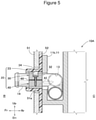
Fig. 5 is a sectional view of a state wherein a holder member and a hot water collecting pipe of a vehicle air conditioning device according to a second working example are attached to a dash panel as seen from a left side. -
Fig. 6 is an exploded perspective view of a holder member and hot water pipes of a vehicle air conditioning device according to a third working example. -
Fig. 7 is a sectional view of a state wherein the holder member and a hot water collecting pipe of the vehicle air conditioning device according to the third working example are attached to a dash panel as seen from a left side. - Hereafter, an embodiment of the invention will be described based on the attached drawings. Fr in the drawings indicates a front with respect to a direction of travel of a vehicle, Rr represents a rear with respect to the direction of travel of the vehicle, Le indicates left as seen by an occupant, Ri indicates right as seen by the occupant, Up indicates up, and Dn indicates down.
- Reference will be made to
Fig. 1 . A vehicle air conditioning device 10 (hereafter written as "air conditioning device 10") is shown inFig. 1 . A main portion of theair conditioning device 10 is disposed inside a vehicle cabin C in which an occupant rides. A forward compartment R in which an engine is housed is formed in front of theair conditioning device 10. The vehicle cabin C and the front compartment R are divided by a dash panel, which is a plate-form member. The dash panel will be described hereafter. - When an engine is housed, the forward compartment R is a region generally called an engine room. As a vehicle in which the
air conditioning device 10 is mounted is not limited to being a vehicle having an engine as a power source, the term "forward compartment R" is used. - The
air conditioning device 10 has acase 11 wherein air is fed into an internal space 11a, a heater core 12, disposed in the internal space 11a, for warming air that has been fed in, a hotwater supply pipe 13 that is connected to the heater core 12 from an exterior of thecase 11 and can supply hot water to the heater core 12, a hotwater collecting pipe 14 that is connected from the heater core 12 to the exterior of thecase 11 and can collect hot water that has passed through an interior of the heater core 12, and aholder member 20 that holds the hotwater supply pipe 13 and the hotwater collecting pipe 14. Hereafter, the hotwater supply pipe 13 and the hotwater collecting pipe 14 may be referred to collectively as "hot water pipes - The
case 11 has a protrudingportion 11b that protrudes toward theholder member 20. A front end of the protrudingportion 11b is raised along a rear face of theholder member 20. In addition to the heater core 12, commonly known parts such as a scroll fan for carrying out air feeding and an evaporator for cooling air that has been fed in are housed in thecase 11. Air whose temperature has been regulated in an interior of thecase 11 is fed to the vehicle cabin C, thereby regulating the inside of the vehicle cabin C to an appropriate temperature. - The internal space 11a is formed in a cavity form, and configures one portion of an air flow path.
- The heater core 12 is a commonly known heater core having a large number of tubes through whose interiors hot water flows, is configured of a metal such as an aluminum alloy, and heats air that has been fed in using heat of the hot water.
- The
hot water pipes hot water pipes hot water pipes - The hot
water supply pipe 13, for example, supplies hot water warmed in an engine to the heater core 12, and the hotwater collecting pipe 14 returns the hot water to the engine after a heat exchange is finished in the heater core 12. The hot water returned to the engine is warmed when cooling the engine, and one portion or a whole thereof is supplied to the heater core 12 again. - Reference will be made to
Fig. 3 andFig. 4A . Thehot water pipes portion 11b of the case, and not come into contact with the protrudingportion 11b. This is because when thehot water pipes portion 11b, vibration received by thehot water pipes case 11 via the protrudingportion 11b, which is undesirable. - Reference will be made to
Fig. 2 . Theholder member 20 has afirst holding portion 30 that comes into contact with an upper half periphery of each of thehot water pipes second holding portion 40 that opposes thefirst holding portion 30 and comes into contact with a lower half periphery of each of thehot water pipes portion 23 that fastens thefirst holding portion 30 and thesecond holding portion 40. - Reference will be made to
Fig. 3 andFig. 4A . Theholder member 20 faces apanel hole 51a provided in thedash panel 51. An outer peripheral edge of theholder member 20 is of an elliptical form whose major axis extends from lower right to upper left along an inner peripheral face of thepanel hole 51a (refer also toFig. 1 ). - A
grommet 52 of a rubber material for shock absorption is provided between thedash panel 51 and theholder member 20. One portion of thegrommet 52 faces an interior of thepanel hole 51a. A front face and an outer peripheral face of theholder member 20 are enclosed by thegrommet 52, and a rear face is covered by the protrudingportion 11b. - Reference will be made to
Fig. 2 . Thefirst holding portion 30 is a member for which a metal (for example, an iron-based material) is used as a material. Thefirst holding portion 30 has a first supplyside holding portion 31, which presents an approximate U-form following an outer peripheral face of the hotwater supply pipe 13 and holds the hotwater supply pipe 13, a first collectionside holding portion 32, which presents an approximate U-form following an outer peripheral face of the hotwater collecting pipe 14 and holds the hotwater collecting pipe 14, a recessedportion 33, which is formed in a concave form facing upward and extends horizontally, and a fastening portion throughhole 34, whose inner diameter is greater than an outer diameter of thefastening portion 23 and through which thefastening portion 23 passes. - The
second holding portion 40 is a member for which a metal (for example, an iron-based material) is used as a material. Thesecond holding portion 40 has a second supplyside holding portion 41, which presents an approximate U-form following the outer peripheral face of the hotwater supply pipe 13 and holds the hotwater supply pipe 13, a second collectionside holding portion 42, which presents an approximate U-form following the outer peripheral face of the hotwater collecting pipe 14 and holds the hotwater collecting pipe 14, a protrudingportion 43, which protrudes toward the recessedportion 33 in a position coinciding with the recessedportion 33, and afastening hole 44, in which a leading end of thefastening portion 23 is fastened. - A metal such as aluminum, a resin, or the like can also be employed as a material of the first holding
portion 30 and the second holdingportion 40. Materials differing between the first holdingportion 30 and the second holdingportion 40 can also be employed. - Reference will also be made to
Fig. 4B . Thesecond holding portion 40 is provided opposing the first holdingportion 30 across a gap δ. In other words, the first holdingportion 30 and the second holdingportion 40 are fastened to each other in a state wherein a predetermined gap is provided. - A dimensional error occurs within a predetermined range in each of the first holding
portion 30, the second holdingportion 40, the hotwater supply pipe 13, and the hotwater collecting pipe 14. A dimension of each part is set in such a way that even in a provisional case wherein errors in the first holdingportion 30 and the second holdingportion 40 are the greatest among possible errors, and errors in the hotwater supply pipe 13 and the hotwater collecting pipe 14 are the smallest among possible errors, a gap occurs between the first holdingportion 30 and the second holdingportion 40. - Reference will be made to
Fig. 2 . Thefastening portion 23 is configured of a self-tapping screw, and is provided between the hotwater supply pipe 13 and the hotwater collecting pipe 14. Other than a screw, a bolt or the like can also be used, provided that thefastening portion 23 can fasten the first holdingportion 30 and the second holdingportion 40. - The first supply
side holding portion 31 encloses an upper portion of the hotwater supply pipe 13 over approximately half the periphery. More precisely, the first supplyside holding portion 31 covers a length slightly less than that of the upper half periphery of the hotwater supply pipe 13, with a circumferential direction as a reference. - The first collection
side holding portion 32 encloses an upper portion of the hotwater collecting pipe 14 over approximately half the periphery. More precisely, the first collectionside holding portion 32 covers a length slightly less than that of the upper half periphery of the hotwater collecting pipe 14, with a circumferential direction as a reference. - The recessed
portion 33 is formed extending to both left and right ends of a lower face of the first holdingportion 30, except in a region in which the first supplyside holding portion 31 is formed and a region in which the first collectionside holding portion 32 is formed. The recessedportion 33 is formed in two places, to the front and the rear. An arrangement can also be such that a direction in which the recessedportion 33 extends follows a direction in which thepanel hole 51a (refer toFig. 3 ) extends. - The second supply
side holding portion 41 encloses a lower portion of the hotwater supply pipe 13 over approximately half the periphery. More precisely, the second supplyside holding portion 41 covers a length slightly less than that of the lower half periphery of the hotwater supply pipe 13, with the circumferential direction as a reference. - The second collection
side holding portion 42 encloses a lower portion of the hotwater collecting pipe 14 over approximately half the periphery. More precisely, the second collectionside holding portion 42 covers a length slightly less than that of the lower half periphery of the hotwater collecting pipe 14, with the circumferential direction as a reference. - The protruding
portion 43 is formed extending to both left and right ends of an upper face of the second holdingportion 40, except in a region in which the second supplyside holding portion 41 is formed and a region in which the second collectionside holding portion 42 is formed. The protrudingportion 43 is formed in two places, to the front and the rear. An arrangement can also be such that a direction in which the protrudingportion 43 extends follows the direction in which thepanel hole 51a (refer toFig. 3 ) extends. - By each of the first supply
side holding portion 31 and the second supplyside holding portion 41 enclosing approximately a half periphery of the hotwater supply pipe 13, approximately a whole periphery of the hotwater supply pipe 13 is enclosed by the first supplyside holding portion 31 and the second supplyside holding portion 41. - Also, by each of the first collection
side holding portion 32 and the second collectionside holding portion 42 enclosing approximately a half periphery of the hotwater collecting pipe 14, approximately a whole periphery of the hotwater collecting pipe 14 is enclosed by the first collectionside holding portion 32 and the second collectionside holding portion 42. - A configuration may also be such that a protruding portion is formed in the first holding
portion 30 and a recessed portion is formed in the second holdingportion 40. Also, a configuration may be such that the recessedportion 33 is formed in a front portion of the first holdingportion 30 and a protruding portion is formed in a rear portion, while the protrudingportion 43 is formed in a front portion of the second holdingportion 40 and a recessed portion is formed in a rear portion. Furthermore, the recessed portions and the protruding portions may be formed in reverse front and rear. - The heretofore described
air conditioning device 10 achieves the following advantages. - Reference will be made to
Fig. 4A and Fig. 4B . Thefirst holding portion 30 and the second holdingportion 40 are disposed across a gap, and fastened using thefastening portion 23. Assuming a case of adopting a setting wherein the first holdingportion 30 and the second holdingportion 40 are brought into close contact, a gap occurs between thehot water pipes holder member 20 when either of thehot water pipes hot water pipes fastening portion 23, leaving a gap, theholder member 20 can be reliably fastened to the hotwater supply pipe 13 and the hotwater collecting pipe 14, even when there is dimensional variation in each of theholder member 20, the hotwater supply pipe 13, and the hotwater collecting pipe 14. Reference will be made toFig. 1 . By the hotwater supply pipe 13 and the hotwater collecting pipe 14 being held integrally, an apparent mass is increased, and a transmission of vibration to thecase 11 and the like can be restricted. Because of this, theair conditioning device 10 having thehot water pipes - Reference will be made to
Fig. 2 andFig. 4A . Approximately the whole periphery of the hotwater supply pipe 13 is enclosed by the first supplyside holding portion 31 and the second supplyside holding portion 41, and approximately the whole periphery of the hotwater collecting pipe 14 is enclosed by the first collectionside holding portion 32 and the second collectionside holding portion 42. By the hotwater supply pipe 13 and the hotwater collecting pipe 14 being held over approximately the whole periphery, the hotwater supply pipe 13 and the hotwater collecting pipe 14 can be held with greater strength. - The
fastening portion 23 is provided between the hotwater supply pipe 13 and the hotwater collecting pipe 14. Both the hotwater supply pipe 13 and the hotwater collecting pipe 14 can be more reliably held, in addition to which theholder member 20 can be compact. - Reference will be made to
Fig. 4A and Fig. 4B . Thesecond holding portion 40 has the protrudingportion 43, which protrudes toward the first holdingportion 30 and extends in the direction in which thepanel hole 51a extends (an approximately horizontal direction of the vehicle) . Also, the first holdingportion 30 has the recessedportion 33, which covers the protrudingportion 43. By adopting a labyrinth structure, noise from the forward compartment R is restricted from being transmitted into the vehicle cabin C, and the inside of the vehicle cabin C can be rendered quiet. The same advantage can be obtained when the first holdingportion 30 has a protruding portion and the second holdingportion 40 has a recessed portion. - A metal is used as a material of the first holding
portion 30 and the second holdingportion 40. The apparent mass is increased, and transmission of vibration can be further restricted. This advantage is achieved by a metal being used as a material of at least one of the first holdingportion 30 and the second holdingportion 40. When a metal is used as a material of both the first holdingportion 30 and the second holdingportion 40, mass can be particularly increased, which is preferable. - Next, an
air conditioning device 10A according to a second working example will be described, based on the drawings. -
Fig. 5 is represented to correspond toFig. 4A . Theair conditioning device 10A according to the second working example is such that asound insulating member 60 is sandwiched between the first holdingportion 30 and the second holdingportion 40 instead of the recessed portion 33 (refer toFig. 4B ) and the protruding portion 43 (refer toFig. 4B ). Other basic configurations are the same as those of theair conditioning device 10 according to the first working example (refer toFig. 1 ). With regard to portions the same as those in the first working example, the same reference signs will be allotted, and a detailed description will be omitted. - The lower face of the first holding
portion 30 is formed to be flat, and the upper face of the second holdingportion 40 is also formed to be flat. - The
sound insulating member 60 can be configured of a plate in which a material having excellent elasticity, such as rubber, is used, or of an adhesive or the like with which a gap formed between the first holdingportion 30 and the second holdingportion 40 is filled. - For example, when the
sound insulating member 60 is configured of a plate made of rubber, thehot water pipes fastening portion 23 while causing thesound insulating member 60 to distort. - Also, when the
sound insulating member 60 is configured by filling with an adhesive or the like, firstly, the first holdingportion 30 and the second holdingportion 40 are fastened using thefastening portion 23, attaining a state wherein the first holdingportion 30 and the second holdingportion 40 are held with sufficient strength. Subsequently, a gap between the first holdingportion 30 and the second holdingportion 40 is filled with an adhesive. Alternatively, using an adhesive that gradually hardens with the passing of time, the gap between the first holdingportion 30 and the second holdingportion 40 may firstly be filled with the adhesive, and the first holdingportion 30 and the second holdingportion 40 fastened using thefastening portion 23 while an elastic force of the adhesive remains. In this case, an epoxy-based resin or the like can be utilized as the adhesive. - The heretofore described hot water pipe holding structure also achieves predetermined advantages of the invention.
- In addition, the
sound insulating member 60 is sandwiched by the first holdingportion 30 and the second holdingportion 40. Noise from the forward compartment R is restricted from being transmitted into the vehicle cabin C, and the inside of the vehicle cabin C can be rendered quiet. - Next, an
air conditioning device 10B according to a third working example will be described, based on the drawings. A basic configuration relating to theair conditioning device 10B according to the third working example is the same as that of theair conditioning devices - Reference will be made to
Fig. 6 andFig. 7 . Aholder member 20B configuring one portion of theair conditioning device 10B is such that a firstvibration restricting portion 70, which restricts a transmission of vibration from afirst holding portion 30B to thecase 11, is provided between thecase 11 and thefirst holding portion 30B, and a secondvibration restricting portion 80, which restricts a transmission of vibration from asecond holding portion 40B to thecase 11, is provided between thecase 11 and thesecond holding portion 40B. - The
first holding portion 30B is such that in addition to the first supplyside holding portion 31, the first collectionside holding portion 32, and the fastening portion throughhole 34, afirst coupling portion 35 to be coupled to the firstvibration restricting portion 70 is formed integrally. Thefirst coupling portion 35 is formed offset to the rear of the fastening portion throughhole 34, with a direction following axial lines of the hotwater supply pipe 13 and the hotwater collecting pipe 14 as a reference. Also, a volume of thefirst coupling portion 35 is preferably greater than a volume of a region in which the fastening portion throughhole 34 is formed. This is because after the twohot water pipes - The
second holding portion 40B is such that in addition to the second supplyside holding portion 41, the second collectionside holding portion 42, and thefastening hole 44, asecond coupling portion 45 to be coupled to the secondvibration restricting portion 80 is formed integrally. Thesecond coupling portion 45 is formed offset to the rear of thefastening hole 44, with a direction following the axial lines of the hotwater supply pipe 13 and the hotwater collecting pipe 14 as a reference. Also, a volume of thesecond coupling portion 45 is preferably greater than a volume of a region in which thefastening hole 44 is formed. This is because after the twohot water pipes - The
first coupling portion 35 and thesecond coupling portion 45 may also be formed to the front of the fastening portion throughhole 34 and thefastening hole 44. - The first
vibration restricting portion 70 has a first fixedportion 71, which is configured of a rigid body and fixed to thecase 11, a firstelastic portion 72, which couples the first fixedportion 71 and thefirst holding portion 30B and has greater elasticity than the first fixedportion 71, and a firstcase fastening portion 73, which is formed integrated with the first fixedportion 71 and is for fastening afastening member 91 for fixing to thecase 11. - Polypropylene, for example, can be used as a material of the first fixed
portion 71. Also, an ethylene propylene diene monomer rubber (EPDM) can be used as a material of the firstelastic portion 72. The firstelastic portion 72 can also be said to be a region for restricting a transmission of vibration from thefirst holding portion 30B to thecase 11. - The first
elastic portion 72 is formed in a mountain-like form facing forward, and has a firstdisplacement absorbing portion 72a that can absorb a displacement of a length from thefirst holding portion 30B to the first fixedportion 71 by distorting. - The second
vibration restricting portion 80 has a second fixedportion 81, which is configured of a rigid body and fixed to thecase 11, a secondelastic portion 82, which couples the second fixedportion 81 and thesecond holding portion 40B and has greater elasticity than the second fixedportion 81, and a secondcase fastening portion 83, which is formed integrated with the second fixedportion 81 and is for fastening thefastening member 91 for fixing to thecase 11. - Polypropylene, for example, can be used as a material of the second fixed
portion 81. Also, an ethylene propylene diene monomer rubber (EPDM) can be used as a material of the secondelastic portion 82. The secondelastic portion 82 can also be said to be a region for restricting a transmission of vibration from thesecond holding portion 40B to thecase 11. The secondelastic portion 82 is formed in a mountain-like form facing forward, and has a seconddisplacement absorbing portion 82a that can absorb a displacement of a length from thesecond holding portion 40B to the second fixedportion 81 by distorting. - The
first holding portion 30B, the first fixedportion 71, and the firstelastic portion 72 are formed integrally using two-color molding. Also, thesecond holding portion 40B, the second fixedportion 81, and the secondelastic portion 82 are formed integrally using two-color molding. - A shock-absorbing
member 93, which is a sponge-form member and restricts a transmission of vibration from thedash panel 51 to thecase 11, is disposed betweenfelt 53, which acts as a vehicle-side member provided in close contact with thedash panel 51, and the firstvibration restricting portion 70, and between the felt 53 and the secondvibration restricting portion 80. - The
vibration restricting portions elastic portions elastic portions case 11. Also, the material of the first fixedportion 71 and the second fixedportion 81 not being limited to polypropylene, nylon 6-6 or another resin can also be selected. Also, the material of the firstelastic portion 72 and the secondelastic portion 82 not being limited to ethylene propylene diene monomer rubber, hydrogenated nitrile rubber or another soft resin can be used, or the firstelastic portion 72 and the secondelastic portion 82 can be configured by forming a resin sheet into a bellows form. - Furthermore, the
displacement absorbing portions displacement absorbing portions elastic portions displacement absorbing portions elastic portions - The heretofore described hot water pipe holding structure also achieves predetermined advantages of the invention.
- The first
vibration restricting portion 70 is provided between thecase 11 and thefirst holding portion 30B, and the secondvibration restricting portion 80 is provided between thecase 11 and thesecond holding portion 40B. Because of this, vibration can be restricted from being transmitted to thecase 11 via thefirst holding portion 30B and thesecond holding portion 40B. Because of this, theair conditioning device 10B having thehot water pipes - The first
vibration restricting portion 70 has the first fixedportion 71, which is configured of a rigid body, and the firstelastic portion 72, which has greater elasticity than the first fixedportion 71. Also, the secondvibration restricting portion 80 has the second fixedportion 81, which is configured of a rigid body, and the secondelastic portion 82, which has greater elasticity than the second fixedportion 81. By the fixedportions case 11, an increase in a lifespan of a fixed region can be achieved. - The
first holding portion 30B, the first fixedportion 71, and the firstelastic portion 72 are formed integrally, and thesecond holding portion 40B, the second fixedportion 81, and the secondelastic portion 82 are formed integrally. Because of this, work of attaching the holdingportions water supply pipe 13 and the hotwater collecting pipe 14 respectively can be carried out easily. - A vehicle air conditioning device hot water pipe holding structure according to the invention is not limited to those shown in the working examples. For example, working examples can be combined. In other words, a labyrinth structure of an uneven form can be configured of a first holding portion and a second holding portion, and furthermore, a sound insulating member made from a rubber plate can be inserted into a gap between the first holding portion and the second holding portion. Alternatively, a labyrinth structure of an uneven form can be configured of a first holding portion and a second holding portion, and a gap can be filled with an adhesive. Sound insulation improves, and retention of a sound insulating member can also be improved.
- Furthermore, when the
holder member 20B is supported via thevibration restricting portions first holding portion 30B and thesecond holding portion 40B (refer to referencesigns 33 and 43). Also, when theholder member 20B is supported via thevibration restricting portions sound insulating member 60 formed of a rubber plate or an adhesive can be inserted into a gap formed between thefirst holding portion 30B and thesecond holding portion 40B. - Also, the
first holding portion 30B and thefirst coupling portion 35 may be configured of separate bodies, and thesecond holding portion 40B and thesecond coupling portion 45 may be configured of separate bodies. - Provided that the effects and the advantages of the invention are achieved, the invention is not limited to the working examples.
- The vehicle air conditioning device hot water pipe holding structure according to the invention is suitable in a vehicle in which an engine is used as a power source. Description of Reference Numerals and Signs
- 10, 10A, 10B:
- vehicle air conditioning device
- 11 case, 11a:
- internal space
- 12:
- heater core
- 13:
- hot water supply pipe
- 14:
- hot water collecting pipe
- 20, 20B:
- holder member
- 30, 30B:
- first holding portion
- 31:
- first supply side holding portion
- 32:
- first collection side holding portion
- 33:
- recessed portion
- 40, 40B:
- second holding portion
- 41:
- second supply side holding portion
- 42:
- second collection side holding portion
- 43:
- protruding portion
- 51:
- dash panel, 51a panel hole
- 60:
- sound insulating member
- 70:
- first vibration restricting portion
- 71:
- first fixed portion
- 72:
- first elastic portion
- 80:
- second vibration restricting portion
- 81:
- second fixed portion
- 82:
- second elastic portion
- C:
- vehicle cabin
- R:
- forward compartment
Claims (11)
the fastening portion (23) is provided between the hot water supply pipe (13) and the hot water collecting pipe (14) .
a metal is used as a material of at least one of the first holding portion (30, 30B) and the second holding portion (40, 40B) .
Applications Claiming Priority (1)
| Application Number | Priority Date | Filing Date | Title |
|---|---|---|---|
| JP2020153541 | 2020-09-14 |
Publications (2)
| Publication Number | Publication Date |
|---|---|
| EP3967530A1 true EP3967530A1 (en) | 2022-03-16 |
| EP3967530B1 EP3967530B1 (en) | 2023-11-01 |
Family
ID=77801478
Family Applications (1)
| Application Number | Title | Priority Date | Filing Date |
|---|---|---|---|
| EP21196713.8A Active EP3967530B1 (en) | 2020-09-14 | 2021-09-14 | Vehicle air conditioning device hot water pipe holding structure |
Country Status (2)
| Country | Link |
|---|---|
| EP (1) | EP3967530B1 (en) |
| JP (1) | JP6975837B1 (en) |
Citations (6)
| Publication number | Priority date | Publication date | Assignee | Title |
|---|---|---|---|---|
| US5234185A (en) * | 1992-02-21 | 1993-08-10 | General Motors Corporation | Unitary pipe clamp and assembly |
| DE19853150A1 (en) * | 1998-11-18 | 2000-05-25 | Behr Gmbh & Co | Holder for supply pipe has holder parts, fixture with wedge-shaped guide piece, film hinge joining holder pieces, and fastenings |
| US20040069480A1 (en) * | 2001-09-03 | 2004-04-15 | Takehiro Yamamoto | Air conditioner for vehicle |
| JP2006168608A (en) | 2004-12-17 | 2006-06-29 | Japan Climate Systems Corp | Air conditioner for vehicles |
| JP2014162378A (en) * | 2013-02-26 | 2014-09-08 | Keihin Corp | Air conditioner for vehicle |
| KR20150132633A (en) * | 2014-05-15 | 2015-11-26 | 한온시스템 주식회사 | Air conditioner for vehicle |
Family Cites Families (3)
| Publication number | Priority date | Publication date | Assignee | Title |
|---|---|---|---|---|
| JPS6479487A (en) * | 1987-09-21 | 1989-03-24 | Yoshiaki Oi | Piping supporter clamping at one position |
| KR101216128B1 (en) * | 2010-06-01 | 2012-12-27 | 한라공조주식회사 | Pipe fixing member of evaporator for automotive vehicles |
| JP2019166919A (en) * | 2018-03-22 | 2019-10-03 | 株式会社デンソー | Air conditioner with pipe support mechanism |
-
2020
- 2020-12-23 JP JP2020213131A patent/JP6975837B1/en active Active
-
2021
- 2021-09-14 EP EP21196713.8A patent/EP3967530B1/en active Active
Patent Citations (6)
| Publication number | Priority date | Publication date | Assignee | Title |
|---|---|---|---|---|
| US5234185A (en) * | 1992-02-21 | 1993-08-10 | General Motors Corporation | Unitary pipe clamp and assembly |
| DE19853150A1 (en) * | 1998-11-18 | 2000-05-25 | Behr Gmbh & Co | Holder for supply pipe has holder parts, fixture with wedge-shaped guide piece, film hinge joining holder pieces, and fastenings |
| US20040069480A1 (en) * | 2001-09-03 | 2004-04-15 | Takehiro Yamamoto | Air conditioner for vehicle |
| JP2006168608A (en) | 2004-12-17 | 2006-06-29 | Japan Climate Systems Corp | Air conditioner for vehicles |
| JP2014162378A (en) * | 2013-02-26 | 2014-09-08 | Keihin Corp | Air conditioner for vehicle |
| KR20150132633A (en) * | 2014-05-15 | 2015-11-26 | 한온시스템 주식회사 | Air conditioner for vehicle |
Also Published As
| Publication number | Publication date |
|---|---|
| EP3967530B1 (en) | 2023-11-01 |
| JP6975837B1 (en) | 2021-12-01 |
| JP2022048063A (en) | 2022-03-25 |
Similar Documents
| Publication | Publication Date | Title |
|---|---|---|
| US6705672B2 (en) | Vehicular air-conditioning duct structure and forming method, and vehicular electric-wiring fixing structure | |
| KR101647186B1 (en) | Bulkhead sealing assembly | |
| US11242090B2 (en) | Front vehicle body structure for vehicle | |
| JP2001213139A (en) | Air guide duct for vehicles | |
| US6652021B1 (en) | Integrated headliner assembly | |
| US20080265607A1 (en) | Audio bracket fore and aft slip plane | |
| US6767050B2 (en) | Passenger compartment isolator system for automotive vehicle | |
| US20230032188A1 (en) | Holder for fixing an electric compressor | |
| EP3967530B1 (en) | Vehicle air conditioning device hot water pipe holding structure | |
| US11951801B2 (en) | Vehicle air conditioning device hot water pipe holding structure | |
| KR101264954B1 (en) | Air distribution duct in the passenger compartment of a motor vehicle | |
| US20020068521A1 (en) | Vehicle air conditioner and mounting structure | |
| CN107074299B (en) | Bulkhead including support structure and acoustic components | |
| US6802386B2 (en) | Method of muffling the noise of successive components as well as a noise absorber for successive components | |
| JP2019166919A (en) | Air conditioner with pipe support mechanism | |
| US20170313281A1 (en) | Defrost duct with acoustic material inserts | |
| JP4378609B2 (en) | Air duct | |
| JP4452606B2 (en) | Foam filler | |
| US20070243818A1 (en) | Air Guide for front end cooling | |
| JP3858662B2 (en) | Assembly method for on-vehicle equipment | |
| JP2005119469A (en) | Vehicular air duct | |
| JP3864527B2 (en) | Air conditioner for vehicles | |
| JP3366161B2 (en) | Vehicle air conditioner | |
| US6267435B1 (en) | Holding arrangement for a mounted vehicle element and method of making same | |
| KR20080031271A (en) | Air circulation unit for car cabin |
Legal Events
| Date | Code | Title | Description |
|---|---|---|---|
| PUAI | Public reference made under article 153(3) epc to a published international application that has entered the european phase |
Free format text: ORIGINAL CODE: 0009012 |
|
| STAA | Information on the status of an ep patent application or granted ep patent |
Free format text: STATUS: THE APPLICATION HAS BEEN PUBLISHED |
|
| AK | Designated contracting states |
Kind code of ref document: A1 Designated state(s): AL AT BE BG CH CY CZ DE DK EE ES FI FR GB GR HR HU IE IS IT LI LT LU LV MC MK MT NL NO PL PT RO RS SE SI SK SM TR |
|
| STAA | Information on the status of an ep patent application or granted ep patent |
Free format text: STATUS: REQUEST FOR EXAMINATION WAS MADE |
|
| 17P | Request for examination filed |
Effective date: 20220916 |
|
| RBV | Designated contracting states (corrected) |
Designated state(s): AL AT BE BG CH CY CZ DE DK EE ES FI FR GB GR HR HU IE IS IT LI LT LU LV MC MK MT NL NO PL PT RO RS SE SI SK SM TR |
|
| GRAJ | Information related to disapproval of communication of intention to grant by the applicant or resumption of examination proceedings by the epo deleted |
Free format text: ORIGINAL CODE: EPIDOSDIGR1 |
|
| GRAP | Despatch of communication of intention to grant a patent |
Free format text: ORIGINAL CODE: EPIDOSNIGR1 |
|
| GRAP | Despatch of communication of intention to grant a patent |
Free format text: ORIGINAL CODE: EPIDOSNIGR1 |
|
| STAA | Information on the status of an ep patent application or granted ep patent |
Free format text: STATUS: GRANT OF PATENT IS INTENDED |
|
| INTG | Intention to grant announced |
Effective date: 20230609 |
|
| P01 | Opt-out of the competence of the unified patent court (upc) registered |
Effective date: 20230629 |
|
| GRAS | Grant fee paid |
Free format text: ORIGINAL CODE: EPIDOSNIGR3 |
|
| GRAA | (expected) grant |
Free format text: ORIGINAL CODE: 0009210 |
|
| STAA | Information on the status of an ep patent application or granted ep patent |
Free format text: STATUS: THE PATENT HAS BEEN GRANTED |
|
| AK | Designated contracting states |
Kind code of ref document: B1 Designated state(s): AL AT BE BG CH CY CZ DE DK EE ES FI FR GB GR HR HU IE IS IT LI LT LU LV MC MK MT NL NO PL PT RO RS SE SI SK SM TR |
|
| REG | Reference to a national code |
Ref country code: GB Ref legal event code: FG4D |
|
| REG | Reference to a national code |
Ref country code: CH Ref legal event code: EP |
|
| REG | Reference to a national code |
Ref country code: DE Ref legal event code: R096 Ref document number: 602021006384 Country of ref document: DE |
|
| REG | Reference to a national code |
Ref country code: IE Ref legal event code: FG4D |
|
| REG | Reference to a national code |
Ref country code: LT Ref legal event code: MG9D |
|
| REG | Reference to a national code |
Ref country code: NL Ref legal event code: MP Effective date: 20231101 |
|
| PG25 | Lapsed in a contracting state [announced via postgrant information from national office to epo] |
Ref country code: GR Free format text: LAPSE BECAUSE OF FAILURE TO SUBMIT A TRANSLATION OF THE DESCRIPTION OR TO PAY THE FEE WITHIN THE PRESCRIBED TIME-LIMIT Effective date: 20240202 |
|
| PG25 | Lapsed in a contracting state [announced via postgrant information from national office to epo] |
Ref country code: IS Free format text: LAPSE BECAUSE OF FAILURE TO SUBMIT A TRANSLATION OF THE DESCRIPTION OR TO PAY THE FEE WITHIN THE PRESCRIBED TIME-LIMIT Effective date: 20240301 |
|
| PG25 | Lapsed in a contracting state [announced via postgrant information from national office to epo] |
Ref country code: LT Free format text: LAPSE BECAUSE OF FAILURE TO SUBMIT A TRANSLATION OF THE DESCRIPTION OR TO PAY THE FEE WITHIN THE PRESCRIBED TIME-LIMIT Effective date: 20231101 |
|
| REG | Reference to a national code |
Ref country code: AT Ref legal event code: MK05 Ref document number: 1626826 Country of ref document: AT Kind code of ref document: T Effective date: 20231101 |
|
| PG25 | Lapsed in a contracting state [announced via postgrant information from national office to epo] |
Ref country code: NL Free format text: LAPSE BECAUSE OF FAILURE TO SUBMIT A TRANSLATION OF THE DESCRIPTION OR TO PAY THE FEE WITHIN THE PRESCRIBED TIME-LIMIT Effective date: 20231101 |
|
| PG25 | Lapsed in a contracting state [announced via postgrant information from national office to epo] |
Ref country code: AT Free format text: LAPSE BECAUSE OF FAILURE TO SUBMIT A TRANSLATION OF THE DESCRIPTION OR TO PAY THE FEE WITHIN THE PRESCRIBED TIME-LIMIT Effective date: 20231101 |
|
| PG25 | Lapsed in a contracting state [announced via postgrant information from national office to epo] |
Ref country code: ES Free format text: LAPSE BECAUSE OF FAILURE TO SUBMIT A TRANSLATION OF THE DESCRIPTION OR TO PAY THE FEE WITHIN THE PRESCRIBED TIME-LIMIT Effective date: 20231101 |
|
| PG25 | Lapsed in a contracting state [announced via postgrant information from national office to epo] |
Ref country code: NL Free format text: LAPSE BECAUSE OF FAILURE TO SUBMIT A TRANSLATION OF THE DESCRIPTION OR TO PAY THE FEE WITHIN THE PRESCRIBED TIME-LIMIT Effective date: 20231101 Ref country code: LT Free format text: LAPSE BECAUSE OF FAILURE TO SUBMIT A TRANSLATION OF THE DESCRIPTION OR TO PAY THE FEE WITHIN THE PRESCRIBED TIME-LIMIT Effective date: 20231101 Ref country code: IS Free format text: LAPSE BECAUSE OF FAILURE TO SUBMIT A TRANSLATION OF THE DESCRIPTION OR TO PAY THE FEE WITHIN THE PRESCRIBED TIME-LIMIT Effective date: 20240301 Ref country code: GR Free format text: LAPSE BECAUSE OF FAILURE TO SUBMIT A TRANSLATION OF THE DESCRIPTION OR TO PAY THE FEE WITHIN THE PRESCRIBED TIME-LIMIT Effective date: 20240202 Ref country code: ES Free format text: LAPSE BECAUSE OF FAILURE TO SUBMIT A TRANSLATION OF THE DESCRIPTION OR TO PAY THE FEE WITHIN THE PRESCRIBED TIME-LIMIT Effective date: 20231101 Ref country code: BG Free format text: LAPSE BECAUSE OF FAILURE TO SUBMIT A TRANSLATION OF THE DESCRIPTION OR TO PAY THE FEE WITHIN THE PRESCRIBED TIME-LIMIT Effective date: 20240201 Ref country code: AT Free format text: LAPSE BECAUSE OF FAILURE TO SUBMIT A TRANSLATION OF THE DESCRIPTION OR TO PAY THE FEE WITHIN THE PRESCRIBED TIME-LIMIT Effective date: 20231101 Ref country code: PT Free format text: LAPSE BECAUSE OF FAILURE TO SUBMIT A TRANSLATION OF THE DESCRIPTION OR TO PAY THE FEE WITHIN THE PRESCRIBED TIME-LIMIT Effective date: 20240301 |
|
| PG25 | Lapsed in a contracting state [announced via postgrant information from national office to epo] |
Ref country code: SE Free format text: LAPSE BECAUSE OF FAILURE TO SUBMIT A TRANSLATION OF THE DESCRIPTION OR TO PAY THE FEE WITHIN THE PRESCRIBED TIME-LIMIT Effective date: 20231101 Ref country code: RS Free format text: LAPSE BECAUSE OF FAILURE TO SUBMIT A TRANSLATION OF THE DESCRIPTION OR TO PAY THE FEE WITHIN THE PRESCRIBED TIME-LIMIT Effective date: 20231101 Ref country code: PL Free format text: LAPSE BECAUSE OF FAILURE TO SUBMIT A TRANSLATION OF THE DESCRIPTION OR TO PAY THE FEE WITHIN THE PRESCRIBED TIME-LIMIT Effective date: 20231101 Ref country code: NO Free format text: LAPSE BECAUSE OF FAILURE TO SUBMIT A TRANSLATION OF THE DESCRIPTION OR TO PAY THE FEE WITHIN THE PRESCRIBED TIME-LIMIT Effective date: 20240201 Ref country code: LV Free format text: LAPSE BECAUSE OF FAILURE TO SUBMIT A TRANSLATION OF THE DESCRIPTION OR TO PAY THE FEE WITHIN THE PRESCRIBED TIME-LIMIT Effective date: 20231101 Ref country code: HR Free format text: LAPSE BECAUSE OF FAILURE TO SUBMIT A TRANSLATION OF THE DESCRIPTION OR TO PAY THE FEE WITHIN THE PRESCRIBED TIME-LIMIT Effective date: 20231101 |
|
| PG25 | Lapsed in a contracting state [announced via postgrant information from national office to epo] |
Ref country code: DK Free format text: LAPSE BECAUSE OF FAILURE TO SUBMIT A TRANSLATION OF THE DESCRIPTION OR TO PAY THE FEE WITHIN THE PRESCRIBED TIME-LIMIT Effective date: 20231101 |
|
| PG25 | Lapsed in a contracting state [announced via postgrant information from national office to epo] |
Ref country code: CZ Free format text: LAPSE BECAUSE OF FAILURE TO SUBMIT A TRANSLATION OF THE DESCRIPTION OR TO PAY THE FEE WITHIN THE PRESCRIBED TIME-LIMIT Effective date: 20231101 |
|
| PG25 | Lapsed in a contracting state [announced via postgrant information from national office to epo] |
Ref country code: SK Free format text: LAPSE BECAUSE OF FAILURE TO SUBMIT A TRANSLATION OF THE DESCRIPTION OR TO PAY THE FEE WITHIN THE PRESCRIBED TIME-LIMIT Effective date: 20231101 |
|
| PG25 | Lapsed in a contracting state [announced via postgrant information from national office to epo] |
Ref country code: SM Free format text: LAPSE BECAUSE OF FAILURE TO SUBMIT A TRANSLATION OF THE DESCRIPTION OR TO PAY THE FEE WITHIN THE PRESCRIBED TIME-LIMIT Effective date: 20231101 Ref country code: SK Free format text: LAPSE BECAUSE OF FAILURE TO SUBMIT A TRANSLATION OF THE DESCRIPTION OR TO PAY THE FEE WITHIN THE PRESCRIBED TIME-LIMIT Effective date: 20231101 Ref country code: IT Free format text: LAPSE BECAUSE OF FAILURE TO SUBMIT A TRANSLATION OF THE DESCRIPTION OR TO PAY THE FEE WITHIN THE PRESCRIBED TIME-LIMIT Effective date: 20231101 Ref country code: EE Free format text: LAPSE BECAUSE OF FAILURE TO SUBMIT A TRANSLATION OF THE DESCRIPTION OR TO PAY THE FEE WITHIN THE PRESCRIBED TIME-LIMIT Effective date: 20231101 Ref country code: DK Free format text: LAPSE BECAUSE OF FAILURE TO SUBMIT A TRANSLATION OF THE DESCRIPTION OR TO PAY THE FEE WITHIN THE PRESCRIBED TIME-LIMIT Effective date: 20231101 Ref country code: CZ Free format text: LAPSE BECAUSE OF FAILURE TO SUBMIT A TRANSLATION OF THE DESCRIPTION OR TO PAY THE FEE WITHIN THE PRESCRIBED TIME-LIMIT Effective date: 20231101 |
|
| REG | Reference to a national code |
Ref country code: DE Ref legal event code: R097 Ref document number: 602021006384 Country of ref document: DE |
|
| PLBE | No opposition filed within time limit |
Free format text: ORIGINAL CODE: 0009261 |
|
| STAA | Information on the status of an ep patent application or granted ep patent |
Free format text: STATUS: NO OPPOSITION FILED WITHIN TIME LIMIT |
|
| 26N | No opposition filed |
Effective date: 20240802 |
|
| PG25 | Lapsed in a contracting state [announced via postgrant information from national office to epo] |
Ref country code: SI Free format text: LAPSE BECAUSE OF FAILURE TO SUBMIT A TRANSLATION OF THE DESCRIPTION OR TO PAY THE FEE WITHIN THE PRESCRIBED TIME-LIMIT Effective date: 20231101 |
|
| PG25 | Lapsed in a contracting state [announced via postgrant information from national office to epo] |
Ref country code: SI Free format text: LAPSE BECAUSE OF FAILURE TO SUBMIT A TRANSLATION OF THE DESCRIPTION OR TO PAY THE FEE WITHIN THE PRESCRIBED TIME-LIMIT Effective date: 20231101 |
|
| PG25 | Lapsed in a contracting state [announced via postgrant information from national office to epo] |
Ref country code: MC Free format text: LAPSE BECAUSE OF FAILURE TO SUBMIT A TRANSLATION OF THE DESCRIPTION OR TO PAY THE FEE WITHIN THE PRESCRIBED TIME-LIMIT Effective date: 20231101 |
|
| REG | Reference to a national code |
Ref country code: CH Ref legal event code: PL |
|
| PG25 | Lapsed in a contracting state [announced via postgrant information from national office to epo] |
Ref country code: LU Free format text: LAPSE BECAUSE OF NON-PAYMENT OF DUE FEES Effective date: 20240914 |
|
| REG | Reference to a national code |
Ref country code: BE Ref legal event code: MM Effective date: 20240930 |
|
| PG25 | Lapsed in a contracting state [announced via postgrant information from national office to epo] |
Ref country code: BE Free format text: LAPSE BECAUSE OF NON-PAYMENT OF DUE FEES Effective date: 20240930 |
|
| PG25 | Lapsed in a contracting state [announced via postgrant information from national office to epo] |
Ref country code: CH Free format text: LAPSE BECAUSE OF NON-PAYMENT OF DUE FEES Effective date: 20240930 |
|
| PG25 | Lapsed in a contracting state [announced via postgrant information from national office to epo] |
Ref country code: IE Free format text: LAPSE BECAUSE OF NON-PAYMENT OF DUE FEES Effective date: 20240914 |
|
| PG25 | Lapsed in a contracting state [announced via postgrant information from national office to epo] |
Ref country code: FI Free format text: LAPSE BECAUSE OF FAILURE TO SUBMIT A TRANSLATION OF THE DESCRIPTION OR TO PAY THE FEE WITHIN THE PRESCRIBED TIME-LIMIT Effective date: 20231101 |
|
| PGFP | Annual fee paid to national office [announced via postgrant information from national office to epo] |
Ref country code: DE Payment date: 20250916 Year of fee payment: 5 |
|
| PGFP | Annual fee paid to national office [announced via postgrant information from national office to epo] |
Ref country code: FR Payment date: 20250929 Year of fee payment: 5 |
|
| PG25 | Lapsed in a contracting state [announced via postgrant information from national office to epo] |
Ref country code: RO Free format text: LAPSE BECAUSE OF FAILURE TO SUBMIT A TRANSLATION OF THE DESCRIPTION OR TO PAY THE FEE WITHIN THE PRESCRIBED TIME-LIMIT Effective date: 20231101 |
|
| PG25 | Lapsed in a contracting state [announced via postgrant information from national office to epo] |
Ref country code: CY Free format text: LAPSE BECAUSE OF FAILURE TO SUBMIT A TRANSLATION OF THE DESCRIPTION OR TO PAY THE FEE WITHIN THE PRESCRIBED TIME-LIMIT; INVALID AB INITIO Effective date: 20210914 |
|
| PG25 | Lapsed in a contracting state [announced via postgrant information from national office to epo] |
Ref country code: HU Free format text: LAPSE BECAUSE OF FAILURE TO SUBMIT A TRANSLATION OF THE DESCRIPTION OR TO PAY THE FEE WITHIN THE PRESCRIBED TIME-LIMIT; INVALID AB INITIO Effective date: 20210914 |