EP3967527A1 - Tire sensor configuring device and smart tire system including the same - Google Patents
Tire sensor configuring device and smart tire system including the same Download PDFInfo
- Publication number
- EP3967527A1 EP3967527A1 EP21195499.5A EP21195499A EP3967527A1 EP 3967527 A1 EP3967527 A1 EP 3967527A1 EP 21195499 A EP21195499 A EP 21195499A EP 3967527 A1 EP3967527 A1 EP 3967527A1
- Authority
- EP
- European Patent Office
- Prior art keywords
- tire
- sensor
- identification code
- communication module
- packet
- Prior art date
- Legal status (The legal status is an assumption and is not a legal conclusion. Google has not performed a legal analysis and makes no representation as to the accuracy of the status listed.)
- Granted
Links
Images

Classifications
-
- B—PERFORMING OPERATIONS; TRANSPORTING
- B60—VEHICLES IN GENERAL
- B60C—VEHICLE TYRES; TYRE INFLATION; TYRE CHANGING; CONNECTING VALVES TO INFLATABLE ELASTIC BODIES IN GENERAL; DEVICES OR ARRANGEMENTS RELATED TO TYRES
- B60C23/00—Devices for measuring, signalling, controlling, or distributing tyre pressure or temperature, specially adapted for mounting on vehicles; Arrangement of tyre inflating devices on vehicles, e.g. of pumps or of tanks; Tyre cooling arrangements
- B60C23/02—Signalling devices actuated by tyre pressure
- B60C23/04—Signalling devices actuated by tyre pressure mounted on the wheel or tyre
- B60C23/0408—Signalling devices actuated by tyre pressure mounted on the wheel or tyre transmitting the signals by non-mechanical means from the wheel or tyre to a vehicle body mounted receiver
- B60C23/0479—Communicating with external units being not part of the vehicle, e.g. tools for diagnostic, mobile phones, electronic keys or service stations
-
- B—PERFORMING OPERATIONS; TRANSPORTING
- B60—VEHICLES IN GENERAL
- B60C—VEHICLE TYRES; TYRE INFLATION; TYRE CHANGING; CONNECTING VALVES TO INFLATABLE ELASTIC BODIES IN GENERAL; DEVICES OR ARRANGEMENTS RELATED TO TYRES
- B60C23/00—Devices for measuring, signalling, controlling, or distributing tyre pressure or temperature, specially adapted for mounting on vehicles; Arrangement of tyre inflating devices on vehicles, e.g. of pumps or of tanks; Tyre cooling arrangements
- B60C23/02—Signalling devices actuated by tyre pressure
- B60C23/04—Signalling devices actuated by tyre pressure mounted on the wheel or tyre
- B60C23/0408—Signalling devices actuated by tyre pressure mounted on the wheel or tyre transmitting the signals by non-mechanical means from the wheel or tyre to a vehicle body mounted receiver
- B60C23/0415—Automatically identifying wheel mounted units, e.g. after replacement or exchange of wheels
- B60C23/0416—Automatically identifying wheel mounted units, e.g. after replacement or exchange of wheels allocating a corresponding wheel position on vehicle, e.g. front/left or rear/right
-
- H—ELECTRICITY
- H04—ELECTRIC COMMUNICATION TECHNIQUE
- H04L—TRANSMISSION OF DIGITAL INFORMATION, e.g. TELEGRAPHIC COMMUNICATION
- H04L69/00—Network arrangements, protocols or services independent of the application payload and not provided for in the other groups of this subclass
- H04L69/06—Notations for structuring of protocol data, e.g. abstract syntax notation one [ASN.1]
-
- B—PERFORMING OPERATIONS; TRANSPORTING
- B60—VEHICLES IN GENERAL
- B60C—VEHICLE TYRES; TYRE INFLATION; TYRE CHANGING; CONNECTING VALVES TO INFLATABLE ELASTIC BODIES IN GENERAL; DEVICES OR ARRANGEMENTS RELATED TO TYRES
- B60C23/00—Devices for measuring, signalling, controlling, or distributing tyre pressure or temperature, specially adapted for mounting on vehicles; Arrangement of tyre inflating devices on vehicles, e.g. of pumps or of tanks; Tyre cooling arrangements
-
- B—PERFORMING OPERATIONS; TRANSPORTING
- B60—VEHICLES IN GENERAL
- B60C—VEHICLE TYRES; TYRE INFLATION; TYRE CHANGING; CONNECTING VALVES TO INFLATABLE ELASTIC BODIES IN GENERAL; DEVICES OR ARRANGEMENTS RELATED TO TYRES
- B60C23/00—Devices for measuring, signalling, controlling, or distributing tyre pressure or temperature, specially adapted for mounting on vehicles; Arrangement of tyre inflating devices on vehicles, e.g. of pumps or of tanks; Tyre cooling arrangements
- B60C23/001—Devices for manually or automatically controlling or distributing tyre pressure whilst the vehicle is moving
-
- B—PERFORMING OPERATIONS; TRANSPORTING
- B60—VEHICLES IN GENERAL
- B60C—VEHICLE TYRES; TYRE INFLATION; TYRE CHANGING; CONNECTING VALVES TO INFLATABLE ELASTIC BODIES IN GENERAL; DEVICES OR ARRANGEMENTS RELATED TO TYRES
- B60C23/00—Devices for measuring, signalling, controlling, or distributing tyre pressure or temperature, specially adapted for mounting on vehicles; Arrangement of tyre inflating devices on vehicles, e.g. of pumps or of tanks; Tyre cooling arrangements
- B60C23/02—Signalling devices actuated by tyre pressure
- B60C23/04—Signalling devices actuated by tyre pressure mounted on the wheel or tyre
- B60C23/0408—Signalling devices actuated by tyre pressure mounted on the wheel or tyre transmitting the signals by non-mechanical means from the wheel or tyre to a vehicle body mounted receiver
- B60C23/0422—Signalling devices actuated by tyre pressure mounted on the wheel or tyre transmitting the signals by non-mechanical means from the wheel or tyre to a vehicle body mounted receiver characterised by the type of signal transmission means
- B60C23/0433—Radio signals
- B60C23/0435—Vehicle body mounted circuits, e.g. transceiver or antenna fixed to central console, door, roof, mirror or fender
-
- B—PERFORMING OPERATIONS; TRANSPORTING
- B60—VEHICLES IN GENERAL
- B60C—VEHICLE TYRES; TYRE INFLATION; TYRE CHANGING; CONNECTING VALVES TO INFLATABLE ELASTIC BODIES IN GENERAL; DEVICES OR ARRANGEMENTS RELATED TO TYRES
- B60C23/00—Devices for measuring, signalling, controlling, or distributing tyre pressure or temperature, specially adapted for mounting on vehicles; Arrangement of tyre inflating devices on vehicles, e.g. of pumps or of tanks; Tyre cooling arrangements
- B60C23/02—Signalling devices actuated by tyre pressure
- B60C23/04—Signalling devices actuated by tyre pressure mounted on the wheel or tyre
- B60C23/0408—Signalling devices actuated by tyre pressure mounted on the wheel or tyre transmitting the signals by non-mechanical means from the wheel or tyre to a vehicle body mounted receiver
- B60C23/0422—Signalling devices actuated by tyre pressure mounted on the wheel or tyre transmitting the signals by non-mechanical means from the wheel or tyre to a vehicle body mounted receiver characterised by the type of signal transmission means
- B60C23/0433—Radio signals
- B60C23/0447—Wheel or tyre mounted circuits
- B60C23/0455—Transmission control of wireless signals
- B60C23/0462—Structure of transmission protocol
-
- B—PERFORMING OPERATIONS; TRANSPORTING
- B60—VEHICLES IN GENERAL
- B60C—VEHICLE TYRES; TYRE INFLATION; TYRE CHANGING; CONNECTING VALVES TO INFLATABLE ELASTIC BODIES IN GENERAL; DEVICES OR ARRANGEMENTS RELATED TO TYRES
- B60C23/00—Devices for measuring, signalling, controlling, or distributing tyre pressure or temperature, specially adapted for mounting on vehicles; Arrangement of tyre inflating devices on vehicles, e.g. of pumps or of tanks; Tyre cooling arrangements
- B60C23/02—Signalling devices actuated by tyre pressure
- B60C23/04—Signalling devices actuated by tyre pressure mounted on the wheel or tyre
- B60C23/0408—Signalling devices actuated by tyre pressure mounted on the wheel or tyre transmitting the signals by non-mechanical means from the wheel or tyre to a vehicle body mounted receiver
- B60C23/0471—System initialisation, e.g. upload or calibration of operating parameters
-
- B—PERFORMING OPERATIONS; TRANSPORTING
- B60—VEHICLES IN GENERAL
- B60C—VEHICLE TYRES; TYRE INFLATION; TYRE CHANGING; CONNECTING VALVES TO INFLATABLE ELASTIC BODIES IN GENERAL; DEVICES OR ARRANGEMENTS RELATED TO TYRES
- B60C23/00—Devices for measuring, signalling, controlling, or distributing tyre pressure or temperature, specially adapted for mounting on vehicles; Arrangement of tyre inflating devices on vehicles, e.g. of pumps or of tanks; Tyre cooling arrangements
- B60C23/02—Signalling devices actuated by tyre pressure
- B60C23/04—Signalling devices actuated by tyre pressure mounted on the wheel or tyre
- B60C23/0408—Signalling devices actuated by tyre pressure mounted on the wheel or tyre transmitting the signals by non-mechanical means from the wheel or tyre to a vehicle body mounted receiver
- B60C23/0471—System initialisation, e.g. upload or calibration of operating parameters
- B60C23/0472—System initialisation, e.g. upload or calibration of operating parameters to manually allocate ID codes or mounting positions, e.g. by service technicians
-
- G—PHYSICS
- G06—COMPUTING OR CALCULATING; COUNTING
- G06K—GRAPHICAL DATA READING; PRESENTATION OF DATA; RECORD CARRIERS; HANDLING RECORD CARRIERS
- G06K17/00—Methods or arrangements for effecting co-operative working between equipments covered by two or more of main groups G06K1/00 - G06K15/00, e.g. automatic card files incorporating conveying and reading operations
- G06K17/0022—Methods or arrangements for effecting co-operative working between equipments covered by two or more of main groups G06K1/00 - G06K15/00, e.g. automatic card files incorporating conveying and reading operations arrangements or provisions for transferring data to distant stations, e.g. from a sensing device
-
- H—ELECTRICITY
- H04—ELECTRIC COMMUNICATION TECHNIQUE
- H04L—TRANSMISSION OF DIGITAL INFORMATION, e.g. TELEGRAPHIC COMMUNICATION
- H04L69/00—Network arrangements, protocols or services independent of the application payload and not provided for in the other groups of this subclass
- H04L69/26—Special purpose or proprietary protocols or architectures
-
- H—ELECTRICITY
- H04—ELECTRIC COMMUNICATION TECHNIQUE
- H04Q—SELECTING
- H04Q9/00—Arrangements in telecontrol or telemetry systems for selectively calling a substation from a main station, in which substation desired apparatus is selected for applying a control signal thereto or for obtaining measured values therefrom
-
- H—ELECTRICITY
- H04—ELECTRIC COMMUNICATION TECHNIQUE
- H04L—TRANSMISSION OF DIGITAL INFORMATION, e.g. TELEGRAPHIC COMMUNICATION
- H04L67/00—Network arrangements or protocols for supporting network services or applications
- H04L67/01—Protocols
- H04L67/12—Protocols specially adapted for proprietary or special-purpose networking environments, e.g. medical networks, sensor networks, networks in vehicles or remote metering networks
-
- H—ELECTRICITY
- H04—ELECTRIC COMMUNICATION TECHNIQUE
- H04Q—SELECTING
- H04Q2209/00—Arrangements in telecontrol or telemetry systems
- H04Q2209/40—Arrangements in telecontrol or telemetry systems using a wireless architecture
- H04Q2209/47—Arrangements in telecontrol or telemetry systems using a wireless architecture using RFID associated with sensors
Definitions
- the present disclosure relates to a tire sensor configuring device and a smart tire system including the same.
- TPMS tire pressure monitoring system
- ABS anti-brake system
- ESP electronic stability program
- a smart tire system that monitors a condition of a tire by attaching a sensor module to an inside of the tire is a representative example.
- a tire air pressure, a temperature, or the like is measured using the sensor module, tire state information is stored on a server or in a cloud, and thus, data on tires of multiple vehicles may be collected and managed at once.
- tire state information is stored on a server or in a cloud, and thus, data on tires of multiple vehicles may be collected and managed at once.
- the sensor module in the smart tire system since the sensor module is attached to an inner liner of the tire, weight and size of the sensor module are limited. Moreover, in preparation for contamination that may occur inside the tire, the sensor module should be completely packed and manufactured. Accordingly, the sensor module has a problem in that it is difficult to provide a separate power supply as hardware.
- An embodiment of the present disclosure is directed to providing a smart tire system including a tire sensor configuring device that operates a sensor module attached to a tire of a vehicle to manage information on the tire in a field of a smart tire system.
- an embodiment of the present disclosure is directed to forming a packet including the tire information according to a protocol that can be handled by a smart tire management server constituting the smart tire system and providing the packet to the smart tire management server.
- a tire sensor configuring device including: a transceiver receiving a communication module identification code of a communication module provided in a vehicle to communicate with a smart tire management server, tire identification codes of a plurality of tires mounted to the vehicle, and sensor identification codes of sensor modules respectively attached to the plurality of tires; and a controller configured to arrange the communication module identification code, the tire identification codes, and the sensor identification codes according to a protocol previously created in association with the smart tire management server to form a packet, wherein the transceiver transmits the packet to the communication module.
- the packet may further include location information of the plurality of tires.
- the protocol may define a location where the tire identification code and the sensor identification code are stored in the packet for each tire.
- the transceiver may include: a transmitter configured to transmit a communication module identification code request signal to the communication module; and a receiver configured to receive the communication module identification code transmitted from the communication module in accordance with the communication module identification code request signal, wherein the receiver receives the sensor identification code and the tire identification code after the receiver receives the communication module identification code.
- the transmitter may transmit a power signal for operating the sensor module to the sensor module after the receiver receives the communication module identification code.
- a smart tire system including: a communication module communicating with a smart tire management server, provided in a vehicle including a plurality of tires, and configured to store a communication module identification code; a sensor module provided in each of the plurality of tires and storing a sensor identification code; a tag provided in each of the plurality of tires and storing a tire identification code; and a tire sensor configuring device communicating with the communication module, the sensor module, and the tag, wherein the tire sensor configuring device includes: a controller configured to arrange the communication module identification code transmitted from the communication module, the sensor identification code transmitted from the sensor module, and the tire identification code transmitted from the tag according to a protocol previously created in association with the smart tire management server to form a packet; and a transceiver transmitting the packet to the communication module.
- the protocol may define a location where the tire identification code and the sensor identification code are stored in the packet for each tire.
- the packet for storing a sensor identification code of the sensor module and a tire identification code of the tire is formed, the packet is transmitted to the smart tire management server, and thus, the data of the tire can be efficiently managed by the smart tire management server.
- the transmitter includes an LF transmitter
- a communication unit of the sensor module includes an LF receiver, and thus, the sensor module can be operated without providing a separate power supply in the sensor module.
- FIGS. 1 to 3 a smart tire system 20 according to an embodiment of the present disclosure will be described with reference to FIGS. 1 to 3 .
- the smart tire system 20 may include a plurality of sensor modules 200, a communication module 300, a smart tire management server 400, and a tire sensor configuring device 500.
- the plurality of sensor modules 200 may be each provided at a plurality of tires 10 provided in a vehicle 1.
- the sensor module 200 may be mounted on an inner liner of each tire 10.
- the sensor module 200 collects tire data such as a temperature, an acceleration, and a wear state of the tire 10 and transmits the tire data to the communication module 300 attached to the vehicle 1.
- the vehicle 1 is shown as a vehicle including four tires 10, but the present disclosure is not limited thereto.
- each of the plurality of sensor modules 200 may store different sensor identification codes, and when the sensor module 200 is operated by the tire sensor configuring device 500, the sensor module 200 may transmit the sensor identification code to the tire sensor configuring device 500.
- the sensor module 200 may include a sensor unit 202, a communication unit 204, and a sensor storage unit 206.
- the sensor unit 202 collects tire data such as the temperature, acceleration, and wear state of the tire 10.
- the sensor unit 202 can be driven by a separate power supply.
- the communication unit 204 transmits tire data to the communication module 300 or the sensor identification code to the tire sensor configuring device 500.
- the communication unit 204 may include a long frequency (LF) receiver that communicates with a long frequency method. Accordingly, when the communication unit 204 receives a power signal transmitted from the tire sensor configuring device 500, the LF receiver generates a wake-up signal, and power is applied according to the wake-up signal to operate the sensor module 200. Therefore, the communication unit 204 may transmit the sensor identification code to the tire sensor configuring device 500.
- LF long frequency
- the sensor storage unit 206 may store the sensor identification code, and may store tire data collected from the sensor unit 202 as the sensor module 200 operates.
- the sensor storage unit 206 may include a memory such as a dynamic random access memory (DRAM) or a NAND.
- a first sensor module 210 attached to a first tire 12 may include a first sensor identification code
- a second sensor module 220 attached to a second tire 14 may include a second sensor identification code.
- the first sensor identification code stored in the sensor storage unit 206 of the first sensor module 210 may be transmitted to the tire sensor configuring device 500 through the communication unit 204 of the first sensor module 210.
- the second sensor identification code of the sensor storage unit 206 of the second sensor module 220 may be transmitted to the tire sensor configuration device 500 through the communication unit 204 of the second sensor module 220.
- the communication module 300 is installed in the vehicle 1, and serves to transmit/receive data on a plurality of tires 10 to/from the smart tire management server 400 or to/from the tire sensor configuring device 500.
- the communication module 300 receives a packet formed in accordance with a protocol P from the tire sensor configuring device 500 and transmits the packet to the smart tire management server 400.
- the communication module 300 and the smart tire management server 400 may communicate in a long-term evolution (LTE) manner and may communicate in a radio frequency (RF) manner with the tire sensor configuring device 500, but the present disclosure is not limited thereto.
- LTE long-term evolution
- RF radio frequency
- the protocol refers to various communication protocols established to facilitate an exchange of information between devices. Accordingly, the protocol applied to the present disclosure may define a location in which the tire identification code and the sensor identification code are stored in the packet P for each of a plurality of tires 10. This will be described in detail below.
- the communication module 300 may include a unique communication module identification code.
- the smart tire management server 400 may receive the packet P configured according to a protocol from the tire sensor configuring device 500.
- the smart tire management server 400 may manage the tire data included in the packet P for each vehicle, and may provide information related to the tire data to a user of the vehicle 1.
- the tire sensor configuring device 500 controls the plurality of sensor modules 200, communicates with the plurality of sensor modules 200 in order to configure the plurality of sensor modules 200, and forms the packet P according to a protocol to transmit the packet P to the smart tire management server 400.
- the tire sensor configuring device 500 may include a transceiver 510 and a controller 520, and a storage unit 530.
- the transceiver 510 receives the communication module identification code of the communication module 300, the tire identification code of each tire 10, and the sensor identification code of each sensor module 200, and transmits the packet formed by the controller 520 to the communication module 300 again.
- a tag for storing a tire identification code may be formed at each of the plurality of tires 10, and the tag may include a radio frequency identification (RFID) tag to communicate with the transceiver 510.
- RFID radio frequency identification
- the transceiver 510 may include a transmitter 512 and a receiver 514.
- the transmitter 512 transmits various signals to the communication module 300 and the sensor module 200 to receive a plurality of sensor identification codes and a plurality of tire identification codes as the transmitter 512 controlled by the controller 520. Specifically, the transmitter 512 may send a communication module identification code request signal to the communication module 300, and when the communication module identification code transmitted from the communication module 300 is received by the receiver 514, the transmitter 512 may be controlled by the controller 520 to sequentially transmit a power signal for operating the sensor module 200 to the plurality of sensor modules 200.
- the transmitter 512 may include an LF transmitter that communicates with the LF receiver of each sensor module 200, and according to a protocol definition, the power signal may be transmitted to a plurality of sensor modules 200 by the LF transmitter.
- the transmitter 512 may further include a radio frequency (RF) transmitter, a long-term evolution (LTE) modem, and the like.
- RF radio frequency
- LTE long-term evolution
- the power signal may be sequentially transmitted to the plurality of sensor modules 200 according to the order of tire locations defined in the protocol.
- the transmitter 512 is controlled by the controller 520 according to the protocol definition, and first transmits the power signal to the first sensor module 210 to operate the first sensor module 210. After the first sensor identification code is received by the receiver 514, the transmitter 512 may transmit the power signal to the second sensor module 220 to operate the second sensor module 220 so that the second sensor identification code is received. Accordingly, the receiver 514 may sequentially receive the sensor identification code and tire identification code for each tire, and the sensor identification code and tire identification code may be stored in the packet P formed by the controller in the order received by the receiver 514. In addition, the transmitter 512 may transmit the packet P formed by the controller 520 to the communication module 300 according to the protocol definition.
- the receiver 514 may receive the identification code from tags provided in the communication module 300, the plurality of sensor modules 200, and the plurality of tires 10. Accordingly, the receiver 514 may receive the communication module identification code transmitted from the communication module 300, and may receive the sensor identification code transmitted from the sensor module 200 operated by the power signal and the tire identification code of the tire to which the operated sensor module is attached.
- the receiver 514 may include an RFID communication unit 204 that communicates with a tag attached to the tire to receive a tire identification code.
- the RFID communication unit 204 may be activated by the controller 520.
- the receiver 514 may sequentially receive the plurality of sensor identification codes and the plurality of tire identification codes according to the power signal sequentially transmitted according to the protocol definition from the transmitter 512.
- the receiver 514 when the receiver 514 receives the first sensor identification code of the first sensor module 210 that has received the power signal, the receiver 514 is controlled by the controller 520 and communicates with the tag of the first tire 12 to which the first sensor module 210 is attached, and thus, the receiver 514 may receive the first tire identification code. Then, when the receiver 514 receives the second sensor identification code of the second sensor module 220 that has received the power signal, the receiver 514 is controlled by the controller 520 and communicates with the tag of the second tire 14 to which the second sensor module 220 is attached, and thus, the receiver 514 may receive the second tire identification code.
- the controller 520 controls the transceiver 510, and according to the protocol previously negotiated with the smart tire management server 400, the controller 520 forms the location information of the plurality of tires 10, the communication module identification code, the plurality of sensor identification codes, the packet P storing the plurality of tire identification codes, as shown in FIG. 3 .
- the controller 520 may form the packet P for storing the plurality of sensor identification codes, the plurality of tire identification codes, and the plurality of tire location information received from the receiver 514 for each tire location in the order of protocol definition, and transmit the packet P to the communication module 300.
- controller 520 may allocate information to each of a plurality of location information.
- allocation information may include numbers or letters. For example, a number assigned to the location information of the first tire may be set to No. 1, and a number assigned to the location information of the second tire may be set to No. 2.
- allocation information includes characters, a character assigned to the first tire location information may be stored as a character representing a front left, and a character assigned to the second tire location information may be stored as a character representing a front right.
- each allocation information may correspond to each location where the tire identification code and the sensor identification code are stored in the packet P for each of the plurality of tires defined in the protocol.
- the controller 520 may control the transmitter 512 to sequentially transmit the power signal to the plurality of sensor modules 200 based on the plurality of allocation information in order to store the location information of the tire, the sensor identification code, and the tire identification code in the packet P according to the protocol.
- the controller 520 may control the transmitter 512 to first transmit the power signal to the first sensor module 210 of the first tire 12 having location information corresponding to the allocation number 1 in the order of the allocation number, and after the first sensor identification code and the first tire identification code are received through the receiver 514, may control the transmitter 512 to transmit the power signal to the second sensor module 220 attached to the second tire 14 having the location information corresponding to the allocation number 2.
- the packet P stores the first received communication module identification code in the receiver 514, and thereafter, according to the definition of the protocol, may store the location information of the first tire, the first identification code number, the first tire identification code, and the location information of the second tire, the second identification code number, and the second tire identification code.
- the controller 520 may extract tire location information, sensor identification code, and tire identification code corresponding to the allocation information called in the packet P. For example, when the allocation number 1 is called, the location information of the first tire 12, the first sensor identification code, and the first tire identification code stored in the packet P may be extracted.
- the allocation information is stored as a number.
- the present disclosure is not limited thereto, and it is applicable even when the allocation information is formed in characters.
- the transmitter 512 of the tire sensor configuring device 500 transmits the communication module identification code request signal to the communication module 300 attached to the vehicle 1, and accordingly, the communication module 300 may transmit the communication module identification code stored therein to the receiver 514 of the tire sensor configuring device 500.
- the controller 520 may store the communication module identification code in the packet P.
- the controller 520 may control the transmitter 512 based on the allocation number to receive the sensor identification code and tire identification code according to the protocol definition. Specifically, the controller 520 may control the transmitter 512 to transmit the power signal to the first sensor module 210 of the first tire 12 located in the location information of the tire corresponding to the allocation number 1, and control the receiver 514 to communicate with the tag of the first tire 12 located in the location information of the tire of which allocation number corresponds to No. 1.
- the first sensor module 210 may be operated, the receiver 514 may receive the first sensor identification code and communicate with the tag to receive the first tire identification code.
- the controller 520 may sequentially store the location information of the first tire 12 to which the first sensor module 210 to which the power signal is transmitted is attached, and the received first sensor identification code and first tire identification code, in the packet P.
- the controller 520 may control the transmitter 512 to transmit a power signal to the second sensor module 220 of the second tire 14 located in the location information of the tire corresponding to the allocation number 2, and control the receiver 514 to communicate with the tag of the second tire 14 located in the location information of the tire of which the allocation number corresponds to No. 2.
- the second sensor module 220 may be operated, and the receiver 514 may receive the second sensor identification code and communicate with the tag to receive the second tire identification code.
- controller 520 may sequentially store the location information of the second tire 14 to which the second sensor module 220 to which the power signal is transmitted is attached, and the received second sensor identification code and the second tire identification code in the packet P after the first sensor identification code and first tire identification code stored in advance.
- the controller 520 may transmit the packet P to the communication module 300 and transmit the packet P to the smart tire management server 400.
- the storage unit 530 may store the location information of the plurality of tires 10 and the allocation information allocated to each of the plurality of location information.
- the controller 520 may store an identification code regarding the new sensor module based on the allocation information. For example, when the first sensor module 210 provided in the first tire 12 is damaged and replaced with a new third sensor module, the controller 520 may control the transmitter 512 to transmit the power signal to the third sensor module. Moreover, the receiver 514 receives the sensor identification code of the third sensor module, the controller 520 may call the existing allocation number 1 to replace the first sensor identification code stored in the packet P with the third sensor identification code.
- the tire sensor configuring device 500 may further include at least one of a display unit (not shown) and an operation unit (not shown).
- the display unit may include a touch pad.
- a user may operate the touch pad or the operation unit to store the location information of the plurality of tires 10, the plurality of sensor identification codes, and the plurality of tire identification codes in the packet P according to the protocol, call at least one of the plurality of allocation information, and control the transmitter 512 and receiver 514.
- the allocation information is called through the controller 520 by operating the touch pad or the operation unit, at least one of the allocation information, the location information of the plurality of tires 10, the plurality of sensor identification codes, and a plurality of tire identification codes may be displayed on the display unit.
- the user may change the allocation information previously stored in the controller into numbers or characters by operating the display unit or the operation unit.
- the user may change the order of allocation numbers allocated to the location information of each tire 10 by operating the display unit or the operation unit.
- the number 1 allocated to the location information of the first tire 12 may be changed to number 2
- the number 2 allocated to the location information of the second tire 14 may be changed to number 1.
- the order of location information of the plurality of tires, the plurality of sensor identification codes, and the plurality of tire identification codes stored in the packet P for each tire location may be changed.
Landscapes
- Engineering & Computer Science (AREA)
- Mechanical Engineering (AREA)
- Computer Networks & Wireless Communication (AREA)
- Signal Processing (AREA)
- Computer Security & Cryptography (AREA)
- General Physics & Mathematics (AREA)
- Physics & Mathematics (AREA)
- Theoretical Computer Science (AREA)
- General Engineering & Computer Science (AREA)
- Computing Systems (AREA)
- Arrangements For Transmission Of Measured Signals (AREA)
- Computer Hardware Design (AREA)
- Microelectronics & Electronic Packaging (AREA)
- Business, Economics & Management (AREA)
- Operations Research (AREA)
- Tourism & Hospitality (AREA)
Abstract
Description
- The present disclosure relates to a tire sensor configuring device and a smart tire system including the same.
- Recently, as an automobile-based technology, research on fuel efficiency, driver convenience, and driving stability improvement is being actively conducted. In particular, active vehicle body stabilization devices such as a tire pressure monitoring system (TPMS), an anti-brake system (ABS), and an electronic stability program (ESP) are becoming common, autonomous vehicles are becoming common, and thus, technologies for more effectively measuring road surface information and tire condition information are researched.
- For example, a smart tire system that monitors a condition of a tire by attaching a sensor module to an inside of the tire is a representative example.
- In such a smart tire system, a tire air pressure, a temperature, or the like is measured using the sensor module, tire state information is stored on a server or in a cloud, and thus, data on tires of multiple vehicles may be collected and managed at once. Meanwhile, in the case of the sensor module in the smart tire system, since the sensor module is attached to an inner liner of the tire, weight and size of the sensor module are limited. Moreover, in preparation for contamination that may occur inside the tire, the sensor module should be completely packed and manufactured. Accordingly, the sensor module has a problem in that it is difficult to provide a separate power supply as hardware.
- In addition, in order for the data collected by the sensor module to be efficiently managed on a server or the like, information on a communication module mounted on the sensor module, tire, and vehicle should be transmitted to the server using a protocol that can be handled or managed by the server.
- An embodiment of the present disclosure is directed to providing a smart tire system including a tire sensor configuring device that operates a sensor module attached to a tire of a vehicle to manage information on the tire in a field of a smart tire system.
- In addition, an embodiment of the present disclosure is directed to forming a packet including the tire information according to a protocol that can be handled by a smart tire management server constituting the smart tire system and providing the packet to the smart tire management server.
- In accordance with a first embodiment of the present disclosure, there is provided a tire sensor configuring device including: a transceiver receiving a communication module identification code of a communication module provided in a vehicle to communicate with a smart tire management server, tire identification codes of a plurality of tires mounted to the vehicle, and sensor identification codes of sensor modules respectively attached to the plurality of tires; and a controller configured to arrange the communication module identification code, the tire identification codes, and the sensor identification codes according to a protocol previously created in association with the smart tire management server to form a packet, wherein the transceiver transmits the packet to the communication module.
- The packet may further include location information of the plurality of tires.
- The protocol may define a location where the tire identification code and the sensor identification code are stored in the packet for each tire.
- The transceiver may include: a transmitter configured to transmit a communication module identification code request signal to the communication module; and a receiver configured to receive the communication module identification code transmitted from the communication module in accordance with the communication module identification code request signal, wherein the receiver receives the sensor identification code and the tire identification code after the receiver receives the communication module identification code.
- The transmitter may transmit a power signal for operating the sensor module to the sensor module after the receiver receives the communication module identification code.
- In accordance with a second embodiment of the present disclosure, there is provided a smart tire system including: a communication module communicating with a smart tire management server, provided in a vehicle including a plurality of tires, and configured to store a communication module identification code; a sensor module provided in each of the plurality of tires and storing a sensor identification code; a tag provided in each of the plurality of tires and storing a tire identification code; and a tire sensor configuring device communicating with the communication module, the sensor module, and the tag, wherein the tire sensor configuring device includes: a controller configured to arrange the communication module identification code transmitted from the communication module, the sensor identification code transmitted from the sensor module, and the tire identification code transmitted from the tag according to a protocol previously created in association with the smart tire management server to form a packet; and a transceiver transmitting the packet to the communication module.
- The protocol may define a location where the tire identification code and the sensor identification code are stored in the packet for each tire.
- According to the protocol previously created in the tire sensor configuring device included in the smart tire system according to the embodiment of the present disclosure, the packet for storing a sensor identification code of the sensor module and a tire identification code of the tire is formed, the packet is transmitted to the smart tire management server, and thus, the data of the tire can be efficiently managed by the smart tire management server.
- The transmitter includes an LF transmitter, a communication unit of the sensor module includes an LF receiver, and thus, the sensor module can be operated without providing a separate power supply in the sensor module.
-
-
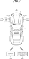
FIG. 1 is a view schematically showing a smart tire system according to an embodiment of the present disclosure. -
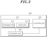
FIG. 2 is a block diagram of a tire sensor configuring device according to the embodiment of the present invention. -
FIG. 3 is a diagram showing a protocol formed by the tire sensor configuring device according to the embodiment of the present invention. - Hereinafter, specific embodiments for implementing a spirit of the present disclosure will be described in detail with reference to the drawings.
- In describing the present disclosure, detailed descriptions of known configurations or functions may be omitted to clarify the present disclosure.
- When an element is referred to as being 'connected' to, 'supported' by, 'accessed' to, 'supplied' to, 'transferred' to, or 'contacted' with another element, it should be understood that the element may be directly connected to, supported by, accessed to, supplied to, transferred to, or contacted with another element, but that other elements may exist in the middle.
- The terms used in the present disclosure are only used for describing specific embodiments, and are not intended to limit the present disclosure. Singular expressions include plural expressions unless the context clearly indicates otherwise.
- Further, in the present disclosure, it is to be noted that expressions, such as the upper side and the lower side, are described based on the illustration of drawings, but may be modified if directions of corresponding objects are changed. For the same reasons, some components are exaggerated, omitted, or schematically illustrated in the accompanying drawings, and the size of each component does not fully reflect the actual size.
- Terms including ordinal numbers, such as first and second, may be used for describing various elements, but the corresponding elements are not limited by these terms. These terms are only used for the purpose of distinguishing one element from another element.
- In the present specification, it is to be understood that the terms such as "including" are intended to indicate the existence of the certain features, areas, integers, steps, actions, elements, combinations, and/or groups thereof disclosed in the specification, and are not intended to preclude the possibility that one or more other certain features, areas, integers, steps, actions, elements, combinations, and/or groups thereof may exist or may be added.
- Hereinafter, a
smart tire system 20 according to an embodiment of the present disclosure will be described with reference toFIGS. 1 to 3 . - Referring to
FIG. 1 , thesmart tire system 20 according to the embodiment of the present disclosure may include a plurality ofsensor modules 200, acommunication module 300, a smarttire management server 400, and a tire sensor configuringdevice 500. - The plurality of
sensor modules 200 may be each provided at a plurality oftires 10 provided in a vehicle 1. Thesensor module 200 may be mounted on an inner liner of eachtire 10. Thesensor module 200 collects tire data such as a temperature, an acceleration, and a wear state of thetire 10 and transmits the tire data to thecommunication module 300 attached to the vehicle 1. As shown inFIG. 1 , the vehicle 1 is shown as a vehicle including fourtires 10, but the present disclosure is not limited thereto. - In addition, each of the plurality of
sensor modules 200 may store different sensor identification codes, and when thesensor module 200 is operated by the tire sensor configuringdevice 500, thesensor module 200 may transmit the sensor identification code to the tire sensor configuringdevice 500. - According to the above, the
sensor module 200 may include asensor unit 202, acommunication unit 204, and asensor storage unit 206. - The
sensor unit 202 collects tire data such as the temperature, acceleration, and wear state of thetire 10. Thesensor unit 202 can be driven by a separate power supply. - The
communication unit 204 transmits tire data to thecommunication module 300 or the sensor identification code to the tire sensor configuringdevice 500. Thecommunication unit 204 may include a long frequency (LF) receiver that communicates with a long frequency method. Accordingly, when thecommunication unit 204 receives a power signal transmitted from the tire sensor configuringdevice 500, the LF receiver generates a wake-up signal, and power is applied according to the wake-up signal to operate thesensor module 200. Therefore, thecommunication unit 204 may transmit the sensor identification code to the tire sensor configuringdevice 500. - The
sensor storage unit 206 may store the sensor identification code, and may store tire data collected from thesensor unit 202 as thesensor module 200 operates. Here, thesensor storage unit 206 may include a memory such as a dynamic random access memory (DRAM) or a NAND. - For example, among the plurality of
sensor modules 200, afirst sensor module 210 attached to afirst tire 12 may include a first sensor identification code, and asecond sensor module 220 attached to asecond tire 14 may include a second sensor identification code. In this case, when a power signal is transmitted to the LF receiver of thefirst sensor module 210, the first sensor identification code stored in thesensor storage unit 206 of thefirst sensor module 210 may be transmitted to the tire sensor configuringdevice 500 through thecommunication unit 204 of thefirst sensor module 210. Then, when the power signal is transmitted to the LF receiver of thesecond sensor module 220, the second sensor identification code of thesensor storage unit 206 of thesecond sensor module 220 may be transmitted to the tiresensor configuration device 500 through thecommunication unit 204 of thesecond sensor module 220. - The
communication module 300 is installed in the vehicle 1, and serves to transmit/receive data on a plurality oftires 10 to/from the smarttire management server 400 or to/from the tire sensor configuringdevice 500. For example, thecommunication module 300 receives a packet formed in accordance with a protocol P from the tire sensor configuringdevice 500 and transmits the packet to the smarttire management server 400. For example, thecommunication module 300 and the smarttire management server 400 may communicate in a long-term evolution (LTE) manner and may communicate in a radio frequency (RF) manner with the tire sensor configuringdevice 500, but the present disclosure is not limited thereto. - Here, the protocol refers to various communication protocols established to facilitate an exchange of information between devices. Accordingly, the protocol applied to the present disclosure may define a location in which the tire identification code and the sensor identification code are stored in the packet P for each of a plurality of
tires 10. This will be described in detail below. - In addition, the
communication module 300 may include a unique communication module identification code. - As the smart
tire management server 400 communicates with thecommunication module 300 mounted on the vehicle 1, the smarttire management server 400 may receive the packet P configured according to a protocol from the tire sensor configuringdevice 500. In addition, the smarttire management server 400 may manage the tire data included in the packet P for each vehicle, and may provide information related to the tire data to a user of the vehicle 1. - The tire
sensor configuring device 500 controls the plurality ofsensor modules 200, communicates with the plurality ofsensor modules 200 in order to configure the plurality ofsensor modules 200, and forms the packet P according to a protocol to transmit the packet P to the smarttire management server 400. - Referring to
FIG. 2 , the tiresensor configuring device 500 may include atransceiver 510 and acontroller 520, and astorage unit 530. - The
transceiver 510 receives the communication module identification code of thecommunication module 300, the tire identification code of eachtire 10, and the sensor identification code of eachsensor module 200, and transmits the packet formed by thecontroller 520 to thecommunication module 300 again. A tag for storing a tire identification code may be formed at each of the plurality oftires 10, and the tag may include a radio frequency identification (RFID) tag to communicate with thetransceiver 510. - The
transceiver 510 may include atransmitter 512 and areceiver 514. - The
transmitter 512 transmits various signals to thecommunication module 300 and thesensor module 200 to receive a plurality of sensor identification codes and a plurality of tire identification codes as thetransmitter 512 controlled by thecontroller 520. Specifically, thetransmitter 512 may send a communication module identification code request signal to thecommunication module 300, and when the communication module identification code transmitted from thecommunication module 300 is received by thereceiver 514, thetransmitter 512 may be controlled by thecontroller 520 to sequentially transmit a power signal for operating thesensor module 200 to the plurality ofsensor modules 200. - The
transmitter 512 may include an LF transmitter that communicates with the LF receiver of eachsensor module 200, and according to a protocol definition, the power signal may be transmitted to a plurality ofsensor modules 200 by the LF transmitter. In addition, thetransmitter 512 may further include a radio frequency (RF) transmitter, a long-term evolution (LTE) modem, and the like. In particular, as described above, since the protocol can define the location where the tire identification code and the sensor identification code are stored in the packet P for each tire or for each tire location, the power signal may be sequentially transmitted to the plurality ofsensor modules 200 according to the order of tire locations defined in the protocol. - According to the above, the
transmitter 512 is controlled by thecontroller 520 according to the protocol definition, and first transmits the power signal to thefirst sensor module 210 to operate thefirst sensor module 210. After the first sensor identification code is received by thereceiver 514, thetransmitter 512 may transmit the power signal to thesecond sensor module 220 to operate thesecond sensor module 220 so that the second sensor identification code is received. Accordingly, thereceiver 514 may sequentially receive the sensor identification code and tire identification code for each tire, and the sensor identification code and tire identification code may be stored in the packet P formed by the controller in the order received by thereceiver 514. In addition, thetransmitter 512 may transmit the packet P formed by thecontroller 520 to thecommunication module 300 according to the protocol definition. - The
receiver 514 may receive the identification code from tags provided in thecommunication module 300, the plurality ofsensor modules 200, and the plurality oftires 10. Accordingly, thereceiver 514 may receive the communication module identification code transmitted from thecommunication module 300, and may receive the sensor identification code transmitted from thesensor module 200 operated by the power signal and the tire identification code of the tire to which the operated sensor module is attached. - The
receiver 514 may include anRFID communication unit 204 that communicates with a tag attached to the tire to receive a tire identification code. TheRFID communication unit 204 may be activated by thecontroller 520. - Accordingly, the
receiver 514 may sequentially receive the plurality of sensor identification codes and the plurality of tire identification codes according to the power signal sequentially transmitted according to the protocol definition from thetransmitter 512. - For example, when the
receiver 514 receives the first sensor identification code of thefirst sensor module 210 that has received the power signal, thereceiver 514 is controlled by thecontroller 520 and communicates with the tag of thefirst tire 12 to which thefirst sensor module 210 is attached, and thus, thereceiver 514 may receive the first tire identification code. Then, when thereceiver 514 receives the second sensor identification code of thesecond sensor module 220 that has received the power signal, thereceiver 514 is controlled by thecontroller 520 and communicates with the tag of thesecond tire 14 to which thesecond sensor module 220 is attached, and thus, thereceiver 514 may receive the second tire identification code. - The
controller 520 controls thetransceiver 510, and according to the protocol previously negotiated with the smarttire management server 400, thecontroller 520 forms the location information of the plurality oftires 10, the communication module identification code, the plurality of sensor identification codes, the packet P storing the plurality of tire identification codes, as shown inFIG. 3 . - Accordingly, the
controller 520 may form the packet P for storing the plurality of sensor identification codes, the plurality of tire identification codes, and the plurality of tire location information received from thereceiver 514 for each tire location in the order of protocol definition, and transmit the packet P to thecommunication module 300. - Moreover, the
controller 520 may allocate information to each of a plurality of location information. - Here, allocation information may include numbers or letters. For example, a number assigned to the location information of the first tire may be set to No. 1, and a number assigned to the location information of the second tire may be set to No. 2. When the allocation information includes characters, a character assigned to the first tire location information may be stored as a character representing a front left, and a character assigned to the second tire location information may be stored as a character representing a front right.
- In addition, each allocation information may correspond to each location where the tire identification code and the sensor identification code are stored in the packet P for each of the plurality of tires defined in the protocol.
- According to the above, the
controller 520 may control thetransmitter 512 to sequentially transmit the power signal to the plurality ofsensor modules 200 based on the plurality of allocation information in order to store the location information of the tire, the sensor identification code, and the tire identification code in the packet P according to the protocol. - For example, the
controller 520 may control thetransmitter 512 to first transmit the power signal to thefirst sensor module 210 of thefirst tire 12 having location information corresponding to the allocation number 1 in the order of the allocation number, and after the first sensor identification code and the first tire identification code are received through thereceiver 514, may control thetransmitter 512 to transmit the power signal to thesecond sensor module 220 attached to thesecond tire 14 having the location information corresponding to the allocation number 2. - As a result, as the power signals are sequentially transmitted to the plurality of
sensor modules 200 in the order of the allocation numbers and the plurality of sensor identification codes and the plurality of tire identification codes are also sequentially received, as shown inFIG. 3 , the packet P stores the first received communication module identification code in thereceiver 514, and thereafter, according to the definition of the protocol, may store the location information of the first tire, the first identification code number, the first tire identification code, and the location information of the second tire, the second identification code number, and the second tire identification code. - Also, when calling any one of the plurality of allocation information, the
controller 520 may extract tire location information, sensor identification code, and tire identification code corresponding to the allocation information called in the packet P. For example, when the allocation number 1 is called, the location information of thefirst tire 12, the first sensor identification code, and the first tire identification code stored in the packet P may be extracted. - Hereinafter, a sequence of forming the packet P according to the protocol of the tire
sensor configuring device 500 according to the embodiment of the present disclosure will be described. In addition, it will be described that the allocation information is stored as a number. However, the present disclosure is not limited thereto, and it is applicable even when the allocation information is formed in characters. - First, the
transmitter 512 of the tiresensor configuring device 500 transmits the communication module identification code request signal to thecommunication module 300 attached to the vehicle 1, and accordingly, thecommunication module 300 may transmit the communication module identification code stored therein to thereceiver 514 of the tiresensor configuring device 500. - As the communication module identification code is received, the
controller 520 may store the communication module identification code in the packet P. - Thereafter, the
controller 520 may control thetransmitter 512 based on the allocation number to receive the sensor identification code and tire identification code according to the protocol definition. Specifically, thecontroller 520 may control thetransmitter 512 to transmit the power signal to thefirst sensor module 210 of thefirst tire 12 located in the location information of the tire corresponding to the allocation number 1, and control thereceiver 514 to communicate with the tag of thefirst tire 12 located in the location information of the tire of which allocation number corresponds to No. 1. - Accordingly, as a power signal is transmitted from the
transmitter 512 to thefirst sensor module 210, thefirst sensor module 210 may be operated, thereceiver 514 may receive the first sensor identification code and communicate with the tag to receive the first tire identification code. - Moreover, the
controller 520 may sequentially store the location information of thefirst tire 12 to which thefirst sensor module 210 to which the power signal is transmitted is attached, and the received first sensor identification code and first tire identification code, in the packet P. - Subsequently, the
controller 520 may control thetransmitter 512 to transmit a power signal to thesecond sensor module 220 of thesecond tire 14 located in the location information of the tire corresponding to the allocation number 2, and control thereceiver 514 to communicate with the tag of thesecond tire 14 located in the location information of the tire of which the allocation number corresponds to No. 2. - Accordingly, as the power signal is transmitted from the
transmitter 512 to thesecond sensor module 220, thesecond sensor module 220 may be operated, and thereceiver 514 may receive the second sensor identification code and communicate with the tag to receive the second tire identification code. - Moreover, the
controller 520 may sequentially store the location information of thesecond tire 14 to which thesecond sensor module 220 to which the power signal is transmitted is attached, and the received second sensor identification code and the second tire identification code in the packet P after the first sensor identification code and first tire identification code stored in advance. - When the tire identification codes of all tires of the vehicle 1 and the sensor identification codes of all
sensor modules 200 are stored in packet P according to the protocol in the above manner, thecontroller 520 may transmit the packet P to thecommunication module 300 and transmit the packet P to the smarttire management server 400. - The
storage unit 530 may store the location information of the plurality oftires 10 and the allocation information allocated to each of the plurality of location information. - Meanwhile, when any one of the
sensor modules 200 attached to the plurality oftires 10 is damaged or does not work and is replaced with a new sensor module, thecontroller 520 may store an identification code regarding the new sensor module based on the allocation information. For example, when thefirst sensor module 210 provided in thefirst tire 12 is damaged and replaced with a new third sensor module, thecontroller 520 may control thetransmitter 512 to transmit the power signal to the third sensor module. Moreover, thereceiver 514 receives the sensor identification code of the third sensor module, thecontroller 520 may call the existing allocation number 1 to replace the first sensor identification code stored in the packet P with the third sensor identification code. - The tire
sensor configuring device 500 according to another embodiment of the present disclosure may further include at least one of a display unit (not shown) and an operation unit (not shown). Here, the display unit may include a touch pad. - Accordingly, a user may operate the touch pad or the operation unit to store the location information of the plurality of
tires 10, the plurality of sensor identification codes, and the plurality of tire identification codes in the packet P according to the protocol, call at least one of the plurality of allocation information, and control thetransmitter 512 andreceiver 514. - In addition, as the allocation information is called through the
controller 520 by operating the touch pad or the operation unit, at least one of the allocation information, the location information of the plurality oftires 10, the plurality of sensor identification codes, and a plurality of tire identification codes may be displayed on the display unit. - In addition, the user may change the allocation information previously stored in the controller into numbers or characters by operating the display unit or the operation unit.
- In addition, the user may change the order of allocation numbers allocated to the location information of each
tire 10 by operating the display unit or the operation unit. For example, the number 1 allocated to the location information of thefirst tire 12 may be changed to number 2, and the number 2 allocated to the location information of thesecond tire 14 may be changed to number 1. In this case, the order of location information of the plurality of tires, the plurality of sensor identification codes, and the plurality of tire identification codes stored in the packet P for each tire location may be changed. - The examples of the present disclosure have been described above as specific embodiments, but these are only examples, and the present disclosure is not limited thereto, and should be construed as having the widest scope according to the technical concept disclosed in the present specification. A person skilled in the art may combine/substitute the disclosed embodiments to implement a pattern of a shape that is not disclosed, but it also does not depart from the scope of the appended claims. In addition, those skilled in the art can easily change or modify the disclosed embodiments based on the present specification, and it is clear that such changes or modifications also belong to the scope of the appended claims.
Claims (7)
- A tire sensor configuring device comprising:a transceiver receiving a communication module identification code of a communication module provided in a vehicle to communicate with a smart tire management server, tire identification codes of a plurality of tires mounted to the vehicle, and sensor identification codes of sensor modules respectively attached to the plurality of tires; anda controller configured to arrange the communication module identification code, the tire identification codes, and the sensor identification codes according to a protocol previously created in association with the smart tire management server to form a packet,wherein the transceiver transmits the packet to the communication module.
- The tire sensor configuration device of claim 1, wherein the packet further includes location information of the plurality of tires.
- The tire sensor configuration device of claim 1 or 2, wherein the protocol defines a location where the tire identification code and the sensor identification code are stored in the packet for each tire.
- The tire sensor configuration device of any one of claims 1 to 3, wherein the transceiver includes:a transmitter configured to transmit a communication module identification code request signal to the communication module; anda receiver configured to receive the communication module identification code transmitted from the communication module in accordance with the communication module identification code request signal,wherein the receiver receives the sensor identification code and the tire identification code after the receiver receives the communication module identification code.
- The tire sensor configuration device of claim 4, wherein the transmitter transmits a power signal for operating the sensor module to the sensor module after the receiver receives the communication module identification code.
- A smart tire system comprising:a communication module communicating with a smart tire management server, provided in a vehicle including a plurality of tires, and configured to store a communication module identification code;a sensor module provided in each of the plurality of tires and storing a sensor identification code;a tag provided in each of the plurality of tires and storing a tire identification code; anda tire sensor configuring device communicating with the communication module, the sensor module, and the tag,wherein the tire sensor configuring device includes:a controller configured to arrange the communication module identification code transmitted from the communication module, the sensor identification code transmitted from the sensor module, and the tire identification code transmitted from the tag according to a protocol previously created in association with the smart tire management server to form a packet; anda transceiver transmitting the packet to the communication module.
- The smart tire system of claim 6, wherein the protocol defines a location where the tire identification code and the sensor identification code are stored in the packet for each tire.
Applications Claiming Priority (1)
| Application Number | Priority Date | Filing Date | Title |
|---|---|---|---|
| KR1020200117887A KR102337097B1 (en) | 2020-09-14 | 2020-09-14 | Tire sensor configuring device and smart tire system including the same |
Publications (2)
| Publication Number | Publication Date |
|---|---|
| EP3967527A1 true EP3967527A1 (en) | 2022-03-16 |
| EP3967527B1 EP3967527B1 (en) | 2025-03-12 |
Family
ID=77666358
Family Applications (1)
| Application Number | Title | Priority Date | Filing Date |
|---|---|---|---|
| EP21195499.5A Active EP3967527B1 (en) | 2020-09-14 | 2021-09-08 | Tire sensor configuring device and smart tire system including the same |
Country Status (4)
| Country | Link |
|---|---|
| US (1) | US20220080787A1 (en) |
| EP (1) | EP3967527B1 (en) |
| KR (1) | KR102337097B1 (en) |
| CN (1) | CN114189561B (en) |
Families Citing this family (1)
| Publication number | Priority date | Publication date | Assignee | Title |
|---|---|---|---|---|
| DE102024207338A1 (en) * | 2024-08-02 | 2026-02-05 | Continental Reifen Deutschland Gmbh | Method for verifying the integrity of a data processing device of a vehicle system |
Citations (4)
| Publication number | Priority date | Publication date | Assignee | Title |
|---|---|---|---|---|
| JP2004322833A (en) * | 2003-04-24 | 2004-11-18 | Bridgestone Corp | Vehicle-mounted receiver and tire-specific information management system including the same |
| EP1946945A1 (en) * | 2005-11-08 | 2008-07-23 | The Yokohama Rubber Co., Ltd. | Vehicle monitoring system |
| FR2971469A1 (en) * | 2011-02-11 | 2012-08-17 | Ldl Technology | Method for managing data relative to tire of wheel assembly of lorry, involves transmitting data associated with identifier to measurement module by intermediate unit that is separated from wheel assembly and vehicle |
| US20150273955A2 (en) * | 2011-04-12 | 2015-10-01 | Compagnie Generale Des Etablissements Michelin | Method of managing data between an rfid marker carried by a tyre and a sensor carried by a rim |
Family Cites Families (26)
| Publication number | Priority date | Publication date | Assignee | Title |
|---|---|---|---|---|
| CA2605850C (en) * | 2005-04-26 | 2012-03-13 | Cooper Tire & Rubber Company | Rfid transmitter for tires and method of manufacture |
| JP2007015454A (en) * | 2005-07-05 | 2007-01-25 | Toyota Motor Corp | Wheel information processing apparatus, wheel state detection system, identification code management system, and identification code assignment method |
| CN102343773B (en) * | 2006-04-25 | 2015-02-04 | 普利司通美国轮胎运营有限责任公司 | Elastomeric article with wireless micro and nano sensor system |
| JP5244353B2 (en) * | 2007-09-14 | 2013-07-24 | 株式会社ブリヂストン | Tire quantity management system |
| TW200930584A (en) * | 2008-01-15 | 2009-07-16 | Mobiletron Electronics Co Ltd | Wireless tire pressure monitoring system |
| KR100951861B1 (en) * | 2008-05-20 | 2010-04-12 | 현대자동차주식회사 | Tire position automatic recognition system |
| US8289144B2 (en) * | 2008-11-28 | 2012-10-16 | Silicon Valley Micro C Corp. | Tire parameter monitoring system with sensor location using RFID tags |
| KR101121130B1 (en) * | 2009-12-03 | 2012-03-19 | 씨트론 주식회사 | System and method for detecting positions of tires |
| JP2012201332A (en) * | 2011-03-28 | 2012-10-22 | Tokai Rika Co Ltd | Tire id registration system |
| JP2012218611A (en) * | 2011-04-11 | 2012-11-12 | Tokai Rika Co Ltd | System for registering tire identification information |
| CN103874592B (en) * | 2011-08-09 | 2018-01-30 | 大陆汽车系统公司 | Device and method for activating a positioning procedure of a tire pressure monitor |
| CN102490555A (en) * | 2011-11-30 | 2012-06-13 | 深圳市元征软件开发有限公司 | Close-range passive tire pressure monitor system and communication method |
| CN202480794U (en) * | 2011-11-30 | 2012-10-10 | 深圳市元征软件开发有限公司 | Short-distance passive tire pressure monitoring system |
| CN203974437U (en) * | 2014-03-17 | 2014-12-03 | 青岛科技大学 | A kind of Intelligent anti-thief tire |
| DE102016213290A1 (en) * | 2015-08-03 | 2017-02-09 | Continental Automotive Systems, Inc. | Apparatus, system and method for configuring a tire information sensor with a transmission protocol based on vehicle trigger characteristics |
| US11073439B2 (en) * | 2015-12-07 | 2021-07-27 | Wegmann Automotive Gmbh | Cross-platform universal tire pressure monitoring sensor |
| US10105997B2 (en) * | 2015-12-21 | 2018-10-23 | The Goodyear Tire & Rubber Company | Integrated TPMS module and RFID tag data sharing system in a tire |
| US10857844B2 (en) * | 2016-01-15 | 2020-12-08 | Infineon Technologies Ag | Tire parameter monitoring system |
| CN107351607A (en) * | 2017-06-20 | 2017-11-17 | 万通智控科技股份有限公司 | A kind of tire management system |
| CN107962917A (en) * | 2017-11-23 | 2018-04-27 | 广东菲柯特电子科技有限公司 | Interactive voice DVD tire pressure instrument |
| CN207601873U (en) * | 2017-12-06 | 2018-07-10 | 广东远峰汽车电子有限公司 | A kind of tire management system applied to car networking |
| CN108058548A (en) * | 2018-01-18 | 2018-05-22 | 深圳市奥比自动控制有限公司 | A kind of passive tire monitoring system |
| JP6969399B2 (en) * | 2018-01-19 | 2021-11-24 | 株式会社Soken | Tire system |
| CN111516439B (en) * | 2019-02-01 | 2022-12-16 | 益力半导体股份有限公司 | In-tire type tire condition monitoring structure |
| WO2020190430A1 (en) * | 2019-03-20 | 2020-09-24 | Bridgestone Americas Tire Operations, Llc | Effective tire pressure sensing system and method |
| US11225110B2 (en) * | 2019-12-17 | 2022-01-18 | Continental Automotive Systems, Inc. | System and method for making protocol changes to a tire pressure monitoring sensor |
-
2020
- 2020-09-14 KR KR1020200117887A patent/KR102337097B1/en active Active
-
2021
- 2021-09-08 EP EP21195499.5A patent/EP3967527B1/en active Active
- 2021-09-08 US US17/469,205 patent/US20220080787A1/en not_active Abandoned
- 2021-09-13 CN CN202111068435.6A patent/CN114189561B/en active Active
Patent Citations (4)
| Publication number | Priority date | Publication date | Assignee | Title |
|---|---|---|---|---|
| JP2004322833A (en) * | 2003-04-24 | 2004-11-18 | Bridgestone Corp | Vehicle-mounted receiver and tire-specific information management system including the same |
| EP1946945A1 (en) * | 2005-11-08 | 2008-07-23 | The Yokohama Rubber Co., Ltd. | Vehicle monitoring system |
| FR2971469A1 (en) * | 2011-02-11 | 2012-08-17 | Ldl Technology | Method for managing data relative to tire of wheel assembly of lorry, involves transmitting data associated with identifier to measurement module by intermediate unit that is separated from wheel assembly and vehicle |
| US20150273955A2 (en) * | 2011-04-12 | 2015-10-01 | Compagnie Generale Des Etablissements Michelin | Method of managing data between an rfid marker carried by a tyre and a sensor carried by a rim |
Also Published As
| Publication number | Publication date |
|---|---|
| US20220080787A1 (en) | 2022-03-17 |
| EP3967527B1 (en) | 2025-03-12 |
| KR102337097B1 (en) | 2021-12-08 |
| CN114189561B (en) | 2024-03-08 |
| CN114189561A (en) | 2022-03-15 |
Similar Documents
| Publication | Publication Date | Title |
|---|---|---|
| US7518495B2 (en) | Universal tire pressure monitor | |
| EP3184329B1 (en) | Integrated tpms module and rfid tag data sharing system in a tire | |
| EP3572248A1 (en) | Identification method for use with tire pressure sensor and relevant device and system | |
| CN102722741A (en) | Vehicle data acquiring device and method based on active radio frequency identification | |
| CN107274715A (en) | A kind of large parking lot parking management system and method | |
| JP2001108551A (en) | Tire pneumatic pressure monitoring device and external communication device | |
| EP3173259A1 (en) | Self-programming tyre pressure monitoring device and implementation method therefor | |
| EP3967527A1 (en) | Tire sensor configuring device and smart tire system including the same | |
| CN108632793A (en) | Vehicle arrangement component, vehicle, the method and transponder for updating function program packet | |
| US20200361255A1 (en) | Tire pressure receiver and instruction processing method | |
| CN105365503A (en) | Universal tire pressure sensor | |
| US20180022169A1 (en) | Tire-monitoring system and method therefor | |
| US10787045B2 (en) | Method, device, computer program, and computer program product for making available data | |
| US20060290485A1 (en) | Tire pressure monitoring system with reliable wireless communication between wheel-based transceivers and vehicle body-based transceiver | |
| CN105391786A (en) | Logistics transportation vehicle-mounted intelligent sensing network structure | |
| CN101848124A (en) | Image forming apparatus, communication device, and communication method | |
| EP2802179B1 (en) | Concurrent activation and data exchange with multiple NFC-A devices | |
| CN103489014B (en) | The sensitivity regulation method and active electronic label of active electronic label | |
| US11260706B2 (en) | Method for pairing a measurement module mounted in a motor vehicle wheel, at the initiative of a computer | |
| WO2023095779A1 (en) | Onboard machine and vehicle information management system | |
| CN208359841U (en) | tire pressure receiver | |
| JP7725997B2 (en) | tire pressure monitoring system | |
| JP2008024175A (en) | Tire condition monitoring device | |
| US12187081B2 (en) | Tire pressure monitoring and location system with tire rotation service indicator and new location confirmation | |
| US20060273906A1 (en) | Method and system for setting parameters of a field station in a communications network |
Legal Events
| Date | Code | Title | Description |
|---|---|---|---|
| PUAI | Public reference made under article 153(3) epc to a published international application that has entered the european phase |
Free format text: ORIGINAL CODE: 0009012 |
|
| STAA | Information on the status of an ep patent application or granted ep patent |
Free format text: STATUS: REQUEST FOR EXAMINATION WAS MADE |
|
| 17P | Request for examination filed |
Effective date: 20210908 |
|
| AK | Designated contracting states |
Kind code of ref document: A1 Designated state(s): AL AT BE BG CH CY CZ DE DK EE ES FI FR GB GR HR HU IE IS IT LI LT LU LV MC MK MT NL NO PL PT RO RS SE SI SK SM TR |
|
| RBV | Designated contracting states (corrected) |
Designated state(s): AL AT BE BG CH CY CZ DE DK EE ES FI FR GB GR HR HU IE IS IT LI LT LU LV MC MK MT NL NO PL PT RO RS SE SI SK SM TR |
|
| RIC1 | Information provided on ipc code assigned before grant |
Ipc: B60C 23/04 20060101AFI20240812BHEP |
|
| GRAP | Despatch of communication of intention to grant a patent |
Free format text: ORIGINAL CODE: EPIDOSNIGR1 |
|
| STAA | Information on the status of an ep patent application or granted ep patent |
Free format text: STATUS: GRANT OF PATENT IS INTENDED |
|
| INTG | Intention to grant announced |
Effective date: 20241004 |
|
| GRAS | Grant fee paid |
Free format text: ORIGINAL CODE: EPIDOSNIGR3 |
|
| GRAA | (expected) grant |
Free format text: ORIGINAL CODE: 0009210 |
|
| STAA | Information on the status of an ep patent application or granted ep patent |
Free format text: STATUS: THE PATENT HAS BEEN GRANTED |
|
| AK | Designated contracting states |
Kind code of ref document: B1 Designated state(s): AL AT BE BG CH CY CZ DE DK EE ES FI FR GB GR HR HU IE IS IT LI LT LU LV MC MK MT NL NO PL PT RO RS SE SI SK SM TR |
|
| REG | Reference to a national code |
Ref country code: GB Ref legal event code: FG4D |
|
| REG | Reference to a national code |
Ref country code: CH Ref legal event code: EP |
|
| REG | Reference to a national code |
Ref country code: DE Ref legal event code: R096 Ref document number: 602021027421 Country of ref document: DE |
|
| REG | Reference to a national code |
Ref country code: IE Ref legal event code: FG4D |
|
| PG25 | Lapsed in a contracting state [announced via postgrant information from national office to epo] |
Ref country code: RS Free format text: LAPSE BECAUSE OF FAILURE TO SUBMIT A TRANSLATION OF THE DESCRIPTION OR TO PAY THE FEE WITHIN THE PRESCRIBED TIME-LIMIT Effective date: 20250612 |
|
| PG25 | Lapsed in a contracting state [announced via postgrant information from national office to epo] |
Ref country code: FI Free format text: LAPSE BECAUSE OF FAILURE TO SUBMIT A TRANSLATION OF THE DESCRIPTION OR TO PAY THE FEE WITHIN THE PRESCRIBED TIME-LIMIT Effective date: 20250312 |
|
| PG25 | Lapsed in a contracting state [announced via postgrant information from national office to epo] |
Ref country code: ES Free format text: LAPSE BECAUSE OF FAILURE TO SUBMIT A TRANSLATION OF THE DESCRIPTION OR TO PAY THE FEE WITHIN THE PRESCRIBED TIME-LIMIT Effective date: 20250312 |
|
| REG | Reference to a national code |
Ref country code: LT Ref legal event code: MG9D |
|
| PG25 | Lapsed in a contracting state [announced via postgrant information from national office to epo] |
Ref country code: NO Free format text: LAPSE BECAUSE OF FAILURE TO SUBMIT A TRANSLATION OF THE DESCRIPTION OR TO PAY THE FEE WITHIN THE PRESCRIBED TIME-LIMIT Effective date: 20250612 |
|
| PG25 | Lapsed in a contracting state [announced via postgrant information from national office to epo] |
Ref country code: HR Free format text: LAPSE BECAUSE OF FAILURE TO SUBMIT A TRANSLATION OF THE DESCRIPTION OR TO PAY THE FEE WITHIN THE PRESCRIBED TIME-LIMIT Effective date: 20250312 |
|
| REG | Reference to a national code |
Ref country code: NL Ref legal event code: MP Effective date: 20250312 |
|
| PG25 | Lapsed in a contracting state [announced via postgrant information from national office to epo] |
Ref country code: LV Free format text: LAPSE BECAUSE OF FAILURE TO SUBMIT A TRANSLATION OF THE DESCRIPTION OR TO PAY THE FEE WITHIN THE PRESCRIBED TIME-LIMIT Effective date: 20250312 |
|
| PG25 | Lapsed in a contracting state [announced via postgrant information from national office to epo] |
Ref country code: BG Free format text: LAPSE BECAUSE OF FAILURE TO SUBMIT A TRANSLATION OF THE DESCRIPTION OR TO PAY THE FEE WITHIN THE PRESCRIBED TIME-LIMIT Effective date: 20250312 Ref country code: GR Free format text: LAPSE BECAUSE OF FAILURE TO SUBMIT A TRANSLATION OF THE DESCRIPTION OR TO PAY THE FEE WITHIN THE PRESCRIBED TIME-LIMIT Effective date: 20250613 |
|
| REG | Reference to a national code |
Ref country code: AT Ref legal event code: MK05 Ref document number: 1774731 Country of ref document: AT Kind code of ref document: T Effective date: 20250312 |
|
| PG25 | Lapsed in a contracting state [announced via postgrant information from national office to epo] |
Ref country code: NL Free format text: LAPSE BECAUSE OF FAILURE TO SUBMIT A TRANSLATION OF THE DESCRIPTION OR TO PAY THE FEE WITHIN THE PRESCRIBED TIME-LIMIT Effective date: 20250312 |
|
| PG25 | Lapsed in a contracting state [announced via postgrant information from national office to epo] |
Ref country code: SE Free format text: LAPSE BECAUSE OF FAILURE TO SUBMIT A TRANSLATION OF THE DESCRIPTION OR TO PAY THE FEE WITHIN THE PRESCRIBED TIME-LIMIT Effective date: 20250312 |
|
| PG25 | Lapsed in a contracting state [announced via postgrant information from national office to epo] |
Ref country code: SM Free format text: LAPSE BECAUSE OF FAILURE TO SUBMIT A TRANSLATION OF THE DESCRIPTION OR TO PAY THE FEE WITHIN THE PRESCRIBED TIME-LIMIT Effective date: 20250312 |
|
| PG25 | Lapsed in a contracting state [announced via postgrant information from national office to epo] |
Ref country code: PT Free format text: LAPSE BECAUSE OF FAILURE TO SUBMIT A TRANSLATION OF THE DESCRIPTION OR TO PAY THE FEE WITHIN THE PRESCRIBED TIME-LIMIT Effective date: 20250714 |
|
| PGFP | Annual fee paid to national office [announced via postgrant information from national office to epo] |
Ref country code: DE Payment date: 20250910 Year of fee payment: 5 |
|
| PG25 | Lapsed in a contracting state [announced via postgrant information from national office to epo] |
Ref country code: PL Free format text: LAPSE BECAUSE OF FAILURE TO SUBMIT A TRANSLATION OF THE DESCRIPTION OR TO PAY THE FEE WITHIN THE PRESCRIBED TIME-LIMIT Effective date: 20250312 Ref country code: IT Free format text: LAPSE BECAUSE OF FAILURE TO SUBMIT A TRANSLATION OF THE DESCRIPTION OR TO PAY THE FEE WITHIN THE PRESCRIBED TIME-LIMIT Effective date: 20250312 |
|
| PG25 | Lapsed in a contracting state [announced via postgrant information from national office to epo] |
Ref country code: AT Free format text: LAPSE BECAUSE OF FAILURE TO SUBMIT A TRANSLATION OF THE DESCRIPTION OR TO PAY THE FEE WITHIN THE PRESCRIBED TIME-LIMIT Effective date: 20250312 |
|
| PGFP | Annual fee paid to national office [announced via postgrant information from national office to epo] |
Ref country code: FR Payment date: 20250922 Year of fee payment: 5 |
|
| PG25 | Lapsed in a contracting state [announced via postgrant information from national office to epo] |
Ref country code: CZ Free format text: LAPSE BECAUSE OF FAILURE TO SUBMIT A TRANSLATION OF THE DESCRIPTION OR TO PAY THE FEE WITHIN THE PRESCRIBED TIME-LIMIT Effective date: 20250312 Ref country code: EE Free format text: LAPSE BECAUSE OF FAILURE TO SUBMIT A TRANSLATION OF THE DESCRIPTION OR TO PAY THE FEE WITHIN THE PRESCRIBED TIME-LIMIT Effective date: 20250312 |
|
| PG25 | Lapsed in a contracting state [announced via postgrant information from national office to epo] |
Ref country code: RO Free format text: LAPSE BECAUSE OF FAILURE TO SUBMIT A TRANSLATION OF THE DESCRIPTION OR TO PAY THE FEE WITHIN THE PRESCRIBED TIME-LIMIT Effective date: 20250312 |
|
| PG25 | Lapsed in a contracting state [announced via postgrant information from national office to epo] |
Ref country code: SK Free format text: LAPSE BECAUSE OF FAILURE TO SUBMIT A TRANSLATION OF THE DESCRIPTION OR TO PAY THE FEE WITHIN THE PRESCRIBED TIME-LIMIT Effective date: 20250312 |
|
| PG25 | Lapsed in a contracting state [announced via postgrant information from national office to epo] |
Ref country code: IS Free format text: LAPSE BECAUSE OF FAILURE TO SUBMIT A TRANSLATION OF THE DESCRIPTION OR TO PAY THE FEE WITHIN THE PRESCRIBED TIME-LIMIT Effective date: 20250712 |
|
| REG | Reference to a national code |
Ref country code: DE Ref legal event code: R097 Ref document number: 602021027421 Country of ref document: DE |
|
| PG25 | Lapsed in a contracting state [announced via postgrant information from national office to epo] |
Ref country code: DK Free format text: LAPSE BECAUSE OF FAILURE TO SUBMIT A TRANSLATION OF THE DESCRIPTION OR TO PAY THE FEE WITHIN THE PRESCRIBED TIME-LIMIT Effective date: 20250312 |
|
| PLBE | No opposition filed within time limit |
Free format text: ORIGINAL CODE: 0009261 |
|
| STAA | Information on the status of an ep patent application or granted ep patent |
Free format text: STATUS: NO OPPOSITION FILED WITHIN TIME LIMIT |
|
| REG | Reference to a national code |
Ref country code: CH Ref legal event code: L10 Free format text: ST27 STATUS EVENT CODE: U-0-0-L10-L00 (AS PROVIDED BY THE NATIONAL OFFICE) Effective date: 20260121 |
|
| 26N | No opposition filed |
Effective date: 20251215 |