EP3967525A1 - Piezoelectric tire - Google Patents
Piezoelectric tire Download PDFInfo
- Publication number
- EP3967525A1 EP3967525A1 EP21191039.3A EP21191039A EP3967525A1 EP 3967525 A1 EP3967525 A1 EP 3967525A1 EP 21191039 A EP21191039 A EP 21191039A EP 3967525 A1 EP3967525 A1 EP 3967525A1
- Authority
- EP
- European Patent Office
- Prior art keywords
- tire
- piezoelectric
- coating type
- tire body
- ground
- Prior art date
- Legal status (The legal status is an assumption and is not a legal conclusion. Google has not performed a legal analysis and makes no representation as to the accuracy of the status listed.)
- Granted
Links
Images





Classifications
-
- B—PERFORMING OPERATIONS; TRANSPORTING
- B60—VEHICLES IN GENERAL
- B60C—VEHICLE TYRES; TYRE INFLATION; TYRE CHANGING; CONNECTING VALVES TO INFLATABLE ELASTIC BODIES IN GENERAL; DEVICES OR ARRANGEMENTS RELATED TO TYRES
- B60C23/00—Devices for measuring, signalling, controlling, or distributing tyre pressure or temperature, specially adapted for mounting on vehicles; Arrangement of tyre inflating devices on vehicles, e.g. of pumps or of tanks; Tyre cooling arrangements
- B60C23/02—Signalling devices actuated by tyre pressure
- B60C23/04—Signalling devices actuated by tyre pressure mounted on the wheel or tyre
- B60C23/0408—Signalling devices actuated by tyre pressure mounted on the wheel or tyre transmitting the signals by non-mechanical means from the wheel or tyre to a vehicle body mounted receiver
- B60C23/041—Means for supplying power to the signal- transmitting means on the wheel
- B60C23/0411—Piezoelectric generators
-
- B—PERFORMING OPERATIONS; TRANSPORTING
- B60—VEHICLES IN GENERAL
- B60C—VEHICLE TYRES; TYRE INFLATION; TYRE CHANGING; CONNECTING VALVES TO INFLATABLE ELASTIC BODIES IN GENERAL; DEVICES OR ARRANGEMENTS RELATED TO TYRES
- B60C19/00—Tyre parts or constructions not otherwise provided for
-
- H—ELECTRICITY
- H02—GENERATION; CONVERSION OR DISTRIBUTION OF ELECTRIC POWER
- H02N—ELECTRIC MACHINES NOT OTHERWISE PROVIDED FOR
- H02N2/00—Electric machines in general using piezoelectric effect, electrostriction or magnetostriction
- H02N2/18—Electric machines in general using piezoelectric effect, electrostriction or magnetostriction producing electrical output from mechanical input, e.g. generators
-
- H—ELECTRICITY
- H10—SEMICONDUCTOR DEVICES; ELECTRIC SOLID-STATE DEVICES NOT OTHERWISE PROVIDED FOR
- H10N—ELECTRIC SOLID-STATE DEVICES NOT OTHERWISE PROVIDED FOR
- H10N30/00—Piezoelectric or electrostrictive devices
- H10N30/30—Piezoelectric or electrostrictive devices with mechanical input and electrical output, e.g. functioning as generators or sensors
-
- H—ELECTRICITY
- H10—SEMICONDUCTOR DEVICES; ELECTRIC SOLID-STATE DEVICES NOT OTHERWISE PROVIDED FOR
- H10N—ELECTRIC SOLID-STATE DEVICES NOT OTHERWISE PROVIDED FOR
- H10N30/00—Piezoelectric or electrostrictive devices
- H10N30/704—Piezoelectric or electrostrictive devices based on piezoelectric or electrostrictive films or coatings
-
- H—ELECTRICITY
- H10—SEMICONDUCTOR DEVICES; ELECTRIC SOLID-STATE DEVICES NOT OTHERWISE PROVIDED FOR
- H10N—ELECTRIC SOLID-STATE DEVICES NOT OTHERWISE PROVIDED FOR
- H10N30/00—Piezoelectric or electrostrictive devices
- H10N30/80—Constructional details
- H10N30/802—Circuitry or processes for operating piezoelectric or electrostrictive devices not otherwise provided for, e.g. drive circuits
-
- B—PERFORMING OPERATIONS; TRANSPORTING
- B60—VEHICLES IN GENERAL
- B60C—VEHICLE TYRES; TYRE INFLATION; TYRE CHANGING; CONNECTING VALVES TO INFLATABLE ELASTIC BODIES IN GENERAL; DEVICES OR ARRANGEMENTS RELATED TO TYRES
- B60C19/00—Tyre parts or constructions not otherwise provided for
- B60C2019/004—Tyre sensors other than for detecting tyre pressure
-
- H—ELECTRICITY
- H10—SEMICONDUCTOR DEVICES; ELECTRIC SOLID-STATE DEVICES NOT OTHERWISE PROVIDED FOR
- H10N—ELECTRIC SOLID-STATE DEVICES NOT OTHERWISE PROVIDED FOR
- H10N30/00—Piezoelectric or electrostrictive devices
- H10N30/80—Constructional details
- H10N30/87—Electrodes or interconnections, e.g. leads or terminals
Definitions
- the present invention relates to a piezoelectric tire for generating electric power corresponding to strain of a ground-contact surface of the tire.
- Japanese Laid-Open Patent Publication No. 2006-223054 discloses a tire including a power generation device.
- the power generation device includes a plurality of power generation elements and a capacitor.
- Each power generation element includes two elastic electrodes and an elastic polymer compound (dielectric elastomer) interposed between the electrodes.
- the elastic polymer compound generates a potential difference between the electrodes on the basis of strain generated in the tire.
- the capacitor stores the electrical energy generated in the power generation element.
- the plurality of power generation elements are provided at at least one side surface inside the tire on a circumference centered on the rotation axis of the tire. The length in the circumferential direction of each power generation element is set such that strain due to compression caused by the rotating tire coming into the ground and strain due to expansion are not applied to the power generation element at the same time.
- each piezoelectric element power generation element
- the two electrodes included in each piezoelectric element are formed by bonding to both surfaces of the dielectric elastomer or by sputtering or vapor deposition.
- the electrodes formed by such a method have a problem about durability. This is because, during running of a vehicle, relatively large tire strain is repeated at a high cycle, and the electrodes are easily peeled off or cracked due to such a harsh usage condition specific to the tire.
- the present invention has been made in view of the above circumstances, and an object of the present invention is to suppress peeling or cracking of electrodes included in a piezoelectric element to improve the durability of a piezoelectric tire.
- the present invention provides a piezoelectric tire including a tire body, a coating type piezoelectric portion, and a circuit unit.
- the coating type piezoelectric portion is coated on the tire body and generates electric power corresponding to strain generated in a ground-contact surface of the tire body.
- the circuit unit is provided to the tire body and driven by the electric power generated by the coating type piezoelectric portion.
- the coating type piezoelectric portion is preferably coated on a back surface of a ground-contact portion of the tire body.
- a resin layer may be provided so as to be interposed between the coating type piezoelectric portion and the tire body such that the coating type piezoelectric portion is not in direct contact with the tire body.
- a length in a width direction of the coating type piezoelectric portion is preferably not less than 70% and not greater than 150% of a ground-contact width under a maximum load in a standard of the Japan Automobile Tyre Manufacturers Association, Inc.
- a length in a circumferential direction of the coating type piezoelectric portion is preferably not less than 40% and not greater than 90% of a ground-contact length under the maximum load in the standard of the Japan Automobile Tyre Manufacturers Association, Inc.
- a plurality of the coating type piezoelectric portions may be provided at different positions in at least either one of a circumferential direction and a width direction of the tire body.
- the plurality of the coating type piezoelectric portions may have lengths different from each other in the circumferential direction, or may have lengths different from each other in the width direction.
- the plurality of the coating type piezoelectric portions may each have a shape obtained by elongating a predetermined shape in at least either one of the circumferential direction and the width direction of the tire body.
- the circuit unit may include a wireless circuit configured to wirelessly transmit a signal of a sensor configured to detect a state of an object to be detected, to the outside.
- the circuit unit may include a power storage unit configured to store the electric power generated by the piezoelectric portion and supply the stored electric power to the circuit unit.
- the piezoelectric portion is in close contact with the tire body and flexibly follows strain of the tire body. Accordingly, peeling or cracking of electrodes included in the coating type piezoelectric portion can be suppressed, so that the durability of the piezoelectric tire can be improved.
- FIG. 1 is a schematic diagram of a piezoelectric tire according to a first embodiment.
- the piezoelectric tire 1A is mounted to an automobile, and can be widely applied to various vehicles such as motorcycles and bicycles although the shape and size thereof are different. Similar to a general tire, the piezoelectric tire 1A is mainly composed of a tire body 2 formed of an elastic body such as rubber, and a piezoelectric portion 3 and a circuit unit 4 are added to the tire body 2.
- the piezoelectric portion 3 is provided on the back surface of a ground-contact portion of the tire body 2 and generates electric power corresponding to strain generated in a ground-contact surface of the tire body 2.
- the piezoelectric portion 3 includes a pair of electrodes arranged on the upper side and the lower side and a piezoelectric film interposed between the electrodes.
- a piezoelectric portion coated on the inner surface of the tire body 2 that is, a coating type piezoelectric portion
- the coating mode include silk printing, screen printing, inkjet printing, coating with a bar coater, and spray coating (see, for example, Japanese Laid-Open Patent Publication No. 2018-157950 ), and bonding, sputtering, and vapor deposition are excluded.
- the lower electrode is coated on the inner surface of the tire body 2, and the piezoelectric film is formed on the upper part of the lower electrode.
- a flexible resin-based piezoelectric material such as polyvinylidene chloride (PVDC), polylactic acid (PLA), polyvinylidene fluoride (PVDF), and a copolymer (P(VDF-TrFE)) of vinylidene fluoride (VDF) and trifluoroethylene (TrFE) is used.
- PVDC polyvinylidene chloride
- PLA polylactic acid
- PVDF polyvinylidene fluoride
- P(VDF-TrFE) copolymer of vinylidene fluoride
- TrFE trifluoroethylene
- the upper electrode is formed on the upper part of the piezoelectric film by using the same method as for the lower electrode.
- the adhesion to the tire body 2 is improved as compared with a non-coating type such as bonding, sputtering, and vapor deposition. Accordingly, peeling or cracking of the electrodes included in the piezoelectric portion 3 can be suppressed while ensuring the followability of the electrodes to strain of the tire body 2.
- a resin layer 5 may be interposed between the piezoelectric portion 3 and the tire body 2.
- the tire body 2 contains a sulfur component, and a phenomenon (bleed-out) that the sulfur component emerges on the surface of the tire body 2 due to aging, is known.
- the piezoelectric portion 3 may be damaged by the sulfur component that emerges on the surface of the tire body 2, causing deterioration or alteration of the piezoelectric portion 3.
- the resin layer 5 is interposed between the piezoelectric portion 3 and the tire body 2 as a protective layer for preventing the piezoelectric portion 3 from being in direct contact with the tire body 2.
- the resin layer 5 is preferably formed by coating such that the resin layer 5 is not easily peeled off from the tire body 2, and preferably does not contain a sulfur component.
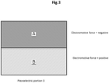
- FIG. 3 is a diagram illustrating electromotive force in the piezoelectric portion 3.
- the direction of strain is locally different, for example, if a compression area A to which the strain is applied and an expansion area B in which the strain is relaxed coexist, electromotive force of one polarity (for example, negative) is generated in the compression area A, while electromotive force of the other polarity (for example, positive) is generated in the expansion area B. Accordingly, the electromotive forces of both polarities are cancelled, causing a decrease in the overall electromotive force of the piezoelectric portion 3.
- one polarity for example, negative
- electromotive force of the other polarity for example, positive
- the overall electromotive force is maximized when the detection surface is occupied by only an area of one polarity.
- the overall electromotive force is minimized when the areas A and B are each present in half. In this case, positive electromotive force and negative electromotive force are completely canceled, so that the overall electromotive force becomes 0. Therefore, when the coating dimensions are set such that coexistence of compression and expansion (in other words, cancellation of positive and negative electromotive forces) is avoided and strain applied to the piezoelectric portion 3 is only compression or expansion, the overall electromotive force can be maximized (amount of power generation can be ensured). This applies to both the circumferential direction and the width direction of the tire.
- the length in the width direction of the piezoelectric portion 3 was examined by the inventors through experiments and simulations, and as a result, the length in the width direction of the piezoelectric portion 3 is preferably in the numerical range of not less than 70% and not greater than 150% of a ground-contact width under the maximum load in the standard of the Japan Automobile Tyre Manufacturers Association, Inc. (JATMA).
- JATMA Japan Automobile Tyre Manufacturers Association
- a tire rim, load, internal pressure, etc. are quoted from the standard specified by JATMA, and values thereof are uniquely determined for each type of tire.
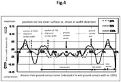
- FIG. 4 is a chart obtained by FEM analysis (finite element method analysis) of strain in the width direction in a tire inner surface.
- the horizontal axis indicates the distance from the ground-contact center with a ground-contact width as 100%, in %.
- the "ground-contact width” refers to the maximum linear distance in the tire axial direction in the surface of the tire that is in contact with a flat plate when the tire is fitted to an applicable rim, the specified air pressure is applied to the tire, the tire is placed on the flat plate so as to be perpendicular to the flat plate in a stationary state, and a load corresponding to a specified mass is applied to the tire.
- the air pressure and the load capacity are specified in advance in this standard.
- the vertical axis indicates the strain (%) in the width direction, where the positive side corresponds to expansion and the negative side corresponds to compression.
- the analysis was carried out with the load applied to the tire being 25%, 58%, and 100% of the maximum load in the JATMA standard.
- the strain distribution in the width direction is symmetrical with respect to the ground-contact center (symmetrical on the front side and the back side of the tire).
- the strain is negative from the ground-contact center to the positions of ⁇ 36% (72% in total) of the ground-contact width under all the three load conditions. Regardless of the magnitude of the load, the strain is in the negative region at positions within 70% that is obtained by taking disturbance factors, variations due to size, etc., into consideration for 72%. In addition, from the ground-contact center to the positions of ⁇ 72% (144% in total) of the ground-contact width, the strain is generally in the negative region under the load conditions of 25% and 58%, but a part of the strain is in the positive region under the load condition of 100%, and the positive and negative strains are present as a whole. Under a condition of a low load (under the full-load condition, when the rear tires are braked, etc.), the strain is only in the negative region at positions within 150% that is obtained by taking disturbance factors, variations due to size, etc., into consideration for 144%.
- the length in the circumferential direction of the piezoelectric portion 3 was examined by the inventors through experiments and simulations, and as a result, the length in the circumferential direction of the piezoelectric portion 3 is preferably not less than 40% and not greater than 90% of the ground-contact length under the maximum load in the JATMA standard.
- FIG. 5 is a chart showing output voltage data obtained when a load was applied to a tire having the piezoelectric portion 3 coated thereon and the tire was rotated.
- the horizontal axis indicates time, and the vertical axis indicates an output voltage.
- the "ground-contact length” refers to the maximum linear distance in the tire circumferential direction in the surface of the tire that is in contact with a flat plate when the tire is fitted to an applicable rim, the specified air pressure is applied to the tire, the tire is placed on the flat plate so as to be perpendicular to the flat plate in a stationary state, and a load corresponding to a specified mass is applied to the tire.
- the piezoelectric portions coated in this example respectively have lengths equal to 54%, 81%, and 108% of the ground-contact length when the ground-contact length is 100%, and the lengths in the width direction thereof are the same.
- a voltage is generated before the piezoelectric portion reaches the ground-contact position and after the piezoelectric portion moves past the ground-contact position.
- the waveforms are generally similar.
- the voltage level in FIG. 5 When the voltage level in FIG. 5 is compared, the voltage level is the highest for 81% of the ground-contact length, is second for 54% of the ground-contact length, and is the lowest for 108% of the ground-contact length.
- the length in the circumferential direction of the piezoelectric portion to be coated needs to be less than the ground-contact length (less than 100% of the ground-contact length). Meanwhile, the length in the circumferential direction by which the tire is deformed by applying a load is the longest at a ground-contact portion on the outermost side, and is the shortest at a tire inner portion due to the thickness of the tread member.
- the voltage data in FIG. 1 In the voltage data in FIG.
- the voltage level is the highest for the length in the circumferential direction of 81%, and when the length in the circumferential direction is less than 100% and equal to or less than 90% that is obtained by taking disturbance factors, variations due to size, etc., into consideration for 81%, an area where strain is compression and an area where strain is expansion do not coexist in one piezoelectric element
- the load during actual running fluctuates in the range of about 25 to 100%.
- the ground-contact length under 25% of the maximum load in the JATMA standard is about 47% of that under 100% of the load, and, in order to prevent positive/negative cancellation within one piezoelectric portion 3 under such a condition, the lower limit is set to 40%. That is, the lower limit of 40% is a value that can cover 47% of the ground-contact length under the maximum load since the ground-contact length is shortened to 47% of the ground-contact length when the load is low (under the no-load condition, when the rear tires are braked, etc.).
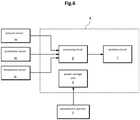
- FIG. 6 is a block diagram of the circuit unit 4.
- the circuit unit 4 has a function of wirelessly outputting the output of sensors for detecting the state of an object to be detected, to the outside, and includes a processing circuit 6, a wireless circuit 7, and a power storage unit 8.
- a pressure sensor 9a, an acceleration sensor 9b, and a temperature sensor 9c are provided as the sensors, and are disposed at appropriate locations such as inside the tire body 2 and on the circuit unit 4.
- the pressure sensor 9a detects the pressure (air pressure) inside the tire body 2.
- the acceleration sensor 9b detects the acceleration of the tire body 2 due to rotation.
- the temperature sensor 9c detects the temperature inside the tire body 2.
- the processing circuit 6 performs signal processing such as AD conversion and noise removal on output signals of the multiple sensors 9a to 9c, and outputs the processed signals to the wireless circuit 7.
- the wireless circuit 7 wirelessly transmits the processed signals of the sensors 9a to 9c to the outside (for example, a computer inside the vehicle).
- the power storage unit 8 includes a rechargeable battery and stores the electric power generated by the piezoelectric portion 3. Then, the stored electric power is supplied to the processing circuit 6 and the wireless circuit 7 in the circuit unit 4.
- the piezoelectric portion 3 is in close contact with the tire body 2, so that peeling or cracking of the electrodes included in the piezoelectric portion 3 can be suppressed.
- the durability of the piezoelectric tire 1A can be improved without impairing the followability to strain of the tire body 2.
- a piezoelectric element is formed by a method other than coating such as attaching a film, it is difficult to follow large strain of a tire made of a flexible material, and the electrodes included in the piezoelectric element are easily peeled off or cracked.
- strain easily becomes uneven or the center of gravity easily deviates.
- the length in the width direction of the piezoelectric portion 3 is set to be not less than 70% and not greater than 150% of the ground-contact width under the maximum load in the JATMA standard and/or the length in the circumferential direction of the piezoelectric portion 3 is set to be not less than 40% and not greater than 90% of the ground-contact width under the maximum load in the JATMA standard, it is possible to effectively ensure an amount of power generation.
- the piezoelectric portion 3 is used for supplying electric power to the circuit unit 4, but can also be used as a sensor for detecting the ground-contact state of the tire body 2 on the basis of a change in output voltage. This point also applies to a second embodiment described below.
- FIG. 7 is a schematic diagram of the piezoelectric tire according to the second embodiment.
- the same components as in the first embodiment are designated by the same reference characters, and the description thereof is omitted here.
- the piezoelectric tire 1B includes a plurality of piezoelectric portions 3a to 3c provided on the back surface of the ground-contact portion of the tire body 2. These piezoelectric portions 3a to 3c have a predetermined shape, and individually generate electric power corresponding to strain generated in the ground-contact surface of the tire body 2. When the plurality of piezoelectric portions 3a to 3c are arranged at intervals, the total amount of power generation (output voltage) can be increased. In the present embodiment, the three piezoelectric portions 3a to 3c are arranged, but the number of piezoelectric portions arranged is arbitrary. In addition, from the viewpoint of the overall weight balance of the piezoelectric tire 1B, the plurality of piezoelectric portions 3a to 3c may be evenly arranged over the entire circumference of the tire body 2.
- FIG. 8 is an arrangement diagram of the plurality of piezoelectric portions 3a to 3c.
- the plurality of piezoelectric portions 3a to 3c are provided at positions different from each other in the circumferential direction of the tire body 2.
- the piezoelectric portions 3a to 3c are all based on a rectangular shape and have a shape obtained by elongating the rectangular shape in the circumferential direction of the tire body 2. That is, the lengths of the piezoelectric portions 3a to 3c in the width direction of the tire body 2 are the same, but the respective lengths La, Lb, and Lc of the piezoelectric portions 3a to 3c in the circumferential direction of the tire body 2 are different from each other (La > Lb > Lc).
- the purpose of coating the plurality of piezoelectric portions 3a to 3c having different lengths in the circumferential direction is to ensure an amount of power generation as in the first embodiment described above.
- the ground-contact length of the tire is proportional to the load, and in actual running, the load fluctuates in the range of 25% to 100% of the ground-contact length under the maximum load in the JATMA standard.
- the compression/expansion of the piezoelectric portions 3 a to 3c also depends on the load. That is, when the lengths in the circumferential direction of the piezoelectric portions 3a to 3c are large and the load is high, only expansion is caused, so that the electromotive force is increased.
- Each of the shapes of the plurality of piezoelectric portions 3a to 3c is not limited to a rectangular shape, and an appropriate shape can be adopted in consideration of the strain shape of the tire body 2 in a ground-contact state.
- a rhombus shape may be used as a base, and the shape of each of the piezoelectric portions 3a to 3c may be a shape obtained by elongating the rhombus shape in the circumferential direction of the tire body 2.
- FIG. 9 a rhombus shape may be used as a base, and the shape of each of the piezoelectric portions 3a to 3c may be a shape obtained by elongating the rhombus shape in the circumferential direction of the tire body 2.
- a shape obtained by line-symmetrically arranging two trapezoids may be used as a base, and the shape of each of the piezoelectric portions 3a to 3c may be a shape obtained by elongating this shape in the circumferential direction of the tire body 2.
- a plurality of piezoelectric portions may be provided at different positions in the width direction of the tire body 2, or may be provided in both the circumferential direction and the width direction of the tire body 2.
- the plurality of piezoelectric portions provided in the width direction may have a shape elongated in the width direction of the tire body 2 as in the case of the circumferential direction.
- the present invention can be regarded not only as an invention of a piezoelectric tire, but also as a method for producing a piezoelectric tire, such as forming the piezoelectric portions 3 and 3a to 3c by coating on the tire body 2.
Landscapes
- Engineering & Computer Science (AREA)
- Mechanical Engineering (AREA)
- Tires In General (AREA)
- General Electrical Machinery Utilizing Piezoelectricity, Electrostriction Or Magnetostriction (AREA)
Abstract
Description
- The present invention relates to a piezoelectric tire for generating electric power corresponding to strain of a ground-contact surface of the tire.
- For example,
Japanese Laid-Open Patent Publication No. 2006-223054 - In
Japanese Laid-Open Patent Publication No. 2006-223054 - The present invention has been made in view of the above circumstances, and an object of the present invention is to suppress peeling or cracking of electrodes included in a piezoelectric element to improve the durability of a piezoelectric tire.
- In order to solve the above problem, the present invention provides a piezoelectric tire including a tire body, a coating type piezoelectric portion, and a circuit unit. The coating type piezoelectric portion is coated on the tire body and generates electric power corresponding to strain generated in a ground-contact surface of the tire body. The circuit unit is provided to the tire body and driven by the electric power generated by the coating type piezoelectric portion.
- In the present invention, the coating type piezoelectric portion is preferably coated on a back surface of a ground-contact portion of the tire body. In addition, a resin layer may be provided so as to be interposed between the coating type piezoelectric portion and the tire body such that the coating type piezoelectric portion is not in direct contact with the tire body. Moreover, a length in a width direction of the coating type piezoelectric portion is preferably not less than 70% and not greater than 150% of a ground-contact width under a maximum load in a standard of the Japan Automobile Tyre Manufacturers Association, Inc. Furthermore, a length in a circumferential direction of the coating type piezoelectric portion is preferably not less than 40% and not greater than 90% of a ground-contact length under the maximum load in the standard of the Japan Automobile Tyre Manufacturers Association, Inc.
- In the present invention, a plurality of the coating type piezoelectric portions may be provided at different positions in at least either one of a circumferential direction and a width direction of the tire body. In this case, the plurality of the coating type piezoelectric portions may have lengths different from each other in the circumferential direction, or may have lengths different from each other in the width direction. In addition, the plurality of the coating type piezoelectric portions may each have a shape obtained by elongating a predetermined shape in at least either one of the circumferential direction and the width direction of the tire body.
- In the present invention, the circuit unit may include a wireless circuit configured to wirelessly transmit a signal of a sensor configured to detect a state of an object to be detected, to the outside. In addition, the circuit unit may include a power storage unit configured to store the electric power generated by the piezoelectric portion and supply the stored electric power to the circuit unit.
- According to the present invention, since the coating type is used as the piezoelectric portion provided on the tire body, the piezoelectric portion is in close contact with the tire body and flexibly follows strain of the tire body. Accordingly, peeling or cracking of electrodes included in the coating type piezoelectric portion can be suppressed, so that the durability of the piezoelectric tire can be improved.
-
-
FIG. 1 is a schematic diagram of a piezoelectric tire according to a first embodiment; -
FIG. 2 is a cross-sectional view of the piezoelectric tire; -
FIG. 3 is a diagram illustrating electromotive force in a piezoelectric portion; -
FIG. 4 is a characteristic diagram of FEM analysis in the width direction of a tire; -
FIG. 5 is a diagram showing output voltage data at the time of rotation of a tire; -
FIG. 6 is a block diagram of a circuit unit; -
FIG. 7 is a schematic diagram of a piezoelectric tire according to a second embodiment; -
FIG. 8 is an arrangement diagram of a plurality of piezoelectric portions; -
FIG. 9 is an arrangement diagram of a plurality of piezoelectric portions according to a first modification; and -
FIG. 10 is an arrangement diagram of a plurality of piezoelectric portions according to a second modification. -
FIG. 1 is a schematic diagram of a piezoelectric tire according to a first embodiment. The piezoelectric tire 1A is mounted to an automobile, and can be widely applied to various vehicles such as motorcycles and bicycles although the shape and size thereof are different. Similar to a general tire, the piezoelectric tire 1A is mainly composed of atire body 2 formed of an elastic body such as rubber, and apiezoelectric portion 3 and acircuit unit 4 are added to thetire body 2. - The
piezoelectric portion 3 is provided on the back surface of a ground-contact portion of thetire body 2 and generates electric power corresponding to strain generated in a ground-contact surface of thetire body 2. Thepiezoelectric portion 3 includes a pair of electrodes arranged on the upper side and the lower side and a piezoelectric film interposed between the electrodes. In the present embodiment, as thepiezoelectric portion 3, a piezoelectric portion coated on the inner surface of thetire body 2, that is, a coating type piezoelectric portion, is used. Examples of the coating mode include silk printing, screen printing, inkjet printing, coating with a bar coater, and spray coating (see, for example,Japanese Laid-Open Patent Publication No. 2018-157950 - Specifically, the lower electrode is coated on the inner surface of the
tire body 2, and the piezoelectric film is formed on the upper part of the lower electrode. As the piezoelectric film, a flexible resin-based piezoelectric material such as polyvinylidene chloride (PVDC), polylactic acid (PLA), polyvinylidene fluoride (PVDF), and a copolymer (P(VDF-TrFE)) of vinylidene fluoride (VDF) and trifluoroethylene (TrFE) is used. The upper electrode is formed on the upper part of the piezoelectric film by using the same method as for the lower electrode. - Since a coating type is used as the
piezoelectric portion 3, the adhesion to thetire body 2 is improved as compared with a non-coating type such as bonding, sputtering, and vapor deposition. Accordingly, peeling or cracking of the electrodes included in thepiezoelectric portion 3 can be suppressed while ensuring the followability of the electrodes to strain of thetire body 2. - Moreover, as shown in
FIG. 2 , aresin layer 5 may be interposed between thepiezoelectric portion 3 and thetire body 2. Generally, thetire body 2 contains a sulfur component, and a phenomenon (bleed-out) that the sulfur component emerges on the surface of thetire body 2 due to aging, is known. In the case where thepiezoelectric portion 3 is in direct contact with the back surface of thetire body 2, thepiezoelectric portion 3 may be damaged by the sulfur component that emerges on the surface of thetire body 2, causing deterioration or alteration of thepiezoelectric portion 3. In order to solve this problem, theresin layer 5 is interposed between thepiezoelectric portion 3 and thetire body 2 as a protective layer for preventing thepiezoelectric portion 3 from being in direct contact with thetire body 2. Theresin layer 5 is preferably formed by coating such that theresin layer 5 is not easily peeled off from thetire body 2, and preferably does not contain a sulfur component. -
FIG. 3 is a diagram illustrating electromotive force in thepiezoelectric portion 3. In general, regardless of whether thepiezoelectric portion 3 is a coating type or not, as a characteristic of a single detection surface of thepiezoelectric portion 3, if the direction of strain is locally different, for example, if a compression area A to which the strain is applied and an expansion area B in which the strain is relaxed coexist, electromotive force of one polarity (for example, negative) is generated in the compression area A, while electromotive force of the other polarity (for example, positive) is generated in the expansion area B. Accordingly, the electromotive forces of both polarities are cancelled, causing a decrease in the overall electromotive force of thepiezoelectric portion 3. The overall electromotive force is maximized when the detection surface is occupied by only an area of one polarity. In addition, the overall electromotive force is minimized when the areas A and B are each present in half. In this case, positive electromotive force and negative electromotive force are completely canceled, so that the overall electromotive force becomes 0. Therefore, when the coating dimensions are set such that coexistence of compression and expansion (in other words, cancellation of positive and negative electromotive forces) is avoided and strain applied to thepiezoelectric portion 3 is only compression or expansion, the overall electromotive force can be maximized (amount of power generation can be ensured). This applies to both the circumferential direction and the width direction of the tire. - Specifically, the length in the width direction of the
piezoelectric portion 3 was examined by the inventors through experiments and simulations, and as a result, the length in the width direction of thepiezoelectric portion 3 is preferably in the numerical range of not less than 70% and not greater than 150% of a ground-contact width under the maximum load in the standard of the Japan Automobile Tyre Manufacturers Association, Inc. (JATMA). Here, a tire rim, load, internal pressure, etc. are quoted from the standard specified by JATMA, and values thereof are uniquely determined for each type of tire. -
FIG. 4 is a chart obtained by FEM analysis (finite element method analysis) of strain in the width direction in a tire inner surface. InFIG. 4 , the horizontal axis indicates the distance from the ground-contact center with a ground-contact width as 100%, in %. Here, the "ground-contact width" refers to the maximum linear distance in the tire axial direction in the surface of the tire that is in contact with a flat plate when the tire is fitted to an applicable rim, the specified air pressure is applied to the tire, the tire is placed on the flat plate so as to be perpendicular to the flat plate in a stationary state, and a load corresponding to a specified mass is applied to the tire. The air pressure and the load capacity are specified in advance in this standard. The vertical axis indicates the strain (%) in the width direction, where the positive side corresponds to expansion and the negative side corresponds to compression. The analysis was carried out with the load applied to the tire being 25%, 58%, and 100% of the maximum load in the JATMA standard. As can be seen fromFIG. 4 , the strain distribution in the width direction is symmetrical with respect to the ground-contact center (symmetrical on the front side and the back side of the tire). - In the FEM analysis, the strain is negative from the ground-contact center to the positions of ±36% (72% in total) of the ground-contact width under all the three load conditions. Regardless of the magnitude of the load, the strain is in the negative region at positions within 70% that is obtained by taking disturbance factors, variations due to size, etc., into consideration for 72%. In addition, from the ground-contact center to the positions of ±72% (144% in total) of the ground-contact width, the strain is generally in the negative region under the load conditions of 25% and 58%, but a part of the strain is in the positive region under the load condition of 100%, and the positive and negative strains are present as a whole. Under a condition of a low load (under the full-load condition, when the rear tires are braked, etc.), the strain is only in the negative region at positions within 150% that is obtained by taking disturbance factors, variations due to size, etc., into consideration for 144%.
- Meanwhile, the length in the circumferential direction of the
piezoelectric portion 3 was examined by the inventors through experiments and simulations, and as a result, the length in the circumferential direction of thepiezoelectric portion 3 is preferably not less than 40% and not greater than 90% of the ground-contact length under the maximum load in the JATMA standard. -
FIG. 5 is a chart showing output voltage data obtained when a load was applied to a tire having thepiezoelectric portion 3 coated thereon and the tire was rotated. The horizontal axis indicates time, and the vertical axis indicates an output voltage. Here, the "ground-contact length" refers to the maximum linear distance in the tire circumferential direction in the surface of the tire that is in contact with a flat plate when the tire is fitted to an applicable rim, the specified air pressure is applied to the tire, the tire is placed on the flat plate so as to be perpendicular to the flat plate in a stationary state, and a load corresponding to a specified mass is applied to the tire. The piezoelectric portions coated in this example respectively have lengths equal to 54%, 81%, and 108% of the ground-contact length when the ground-contact length is 100%, and the lengths in the width direction thereof are the same. As can be seen from the time-series waveforms of voltage, a voltage is generated before the piezoelectric portion reaches the ground-contact position and after the piezoelectric portion moves past the ground-contact position. In addition, even if the lengths in the circumferential direction are different, the waveforms are generally similar. - When the voltage level in
FIG. 5 is compared, the voltage level is the highest for 81% of the ground-contact length, is second for 54% of the ground-contact length, and is the lowest for 108% of the ground-contact length. The reason why the piezoelectric portion with 108% has a low voltage level even though the piezoelectric element amount is the largest among the three conditions, is that as shown inFIG. 3 , an area where strain is compression and an area where strain is expansion coexist in one piezoelectric element, and positive electromotive force and negative electromotive force are cancelled, so that the overall electromotive force is decreased. Therefore, in order to ensure electromagnetic force, the length in the circumferential direction of the piezoelectric portion to be coated needs to be less than the ground-contact length (less than 100% of the ground-contact length). Meanwhile, the length in the circumferential direction by which the tire is deformed by applying a load is the longest at a ground-contact portion on the outermost side, and is the shortest at a tire inner portion due to the thickness of the tread member. In the voltage data inFIG. 5 , the voltage level is the highest for the length in the circumferential direction of 81%, and when the length in the circumferential direction is less than 100% and equal to or less than 90% that is obtained by taking disturbance factors, variations due to size, etc., into consideration for 81%, an area where strain is compression and an area where strain is expansion do not coexist in one piezoelectric element - Meanwhile, the load during actual running fluctuates in the range of about 25 to 100%. The ground-contact length under 25% of the maximum load in the JATMA standard is about 47% of that under 100% of the load, and, in order to prevent positive/negative cancellation within one
piezoelectric portion 3 under such a condition, the lower limit is set to 40%. That is, the lower limit of 40% is a value that can cover 47% of the ground-contact length under the maximum load since the ground-contact length is shortened to 47% of the ground-contact length when the load is low (under the no-load condition, when the rear tires are braked, etc.). - The
circuit unit 4 is provided to thetire body 2 and is driven by the electric power generated by thepiezoelectric portion 3.FIG. 6 is a block diagram of thecircuit unit 4. Thecircuit unit 4 has a function of wirelessly outputting the output of sensors for detecting the state of an object to be detected, to the outside, and includes aprocessing circuit 6, a wireless circuit 7, and apower storage unit 8. In the present embodiment, apressure sensor 9a, anacceleration sensor 9b, and atemperature sensor 9c are provided as the sensors, and are disposed at appropriate locations such as inside thetire body 2 and on thecircuit unit 4. Thepressure sensor 9a detects the pressure (air pressure) inside thetire body 2. Theacceleration sensor 9b detects the acceleration of thetire body 2 due to rotation. In addition, thetemperature sensor 9c detects the temperature inside thetire body 2. - The
processing circuit 6 performs signal processing such as AD conversion and noise removal on output signals of themultiple sensors 9a to 9c, and outputs the processed signals to the wireless circuit 7. The wireless circuit 7 wirelessly transmits the processed signals of thesensors 9a to 9c to the outside (for example, a computer inside the vehicle). In addition, thepower storage unit 8 includes a rechargeable battery and stores the electric power generated by thepiezoelectric portion 3. Then, the stored electric power is supplied to theprocessing circuit 6 and the wireless circuit 7 in thecircuit unit 4. - As described above, according to the present embodiment, since the coating type is used as the
piezoelectric portion 3 provided on thetire body 2, thepiezoelectric portion 3 is in close contact with thetire body 2, so that peeling or cracking of the electrodes included in thepiezoelectric portion 3 can be suppressed. As a result, the durability of the piezoelectric tire 1A can be improved without impairing the followability to strain of thetire body 2. In this respect, for example, when a piezoelectric element is formed by a method other than coating such as attaching a film, it is difficult to follow large strain of a tire made of a flexible material, and the electrodes included in the piezoelectric element are easily peeled off or cracked. In addition, when a device-type power generation element is mounted, strain easily becomes uneven or the center of gravity easily deviates. These problems can be effectively solved by using the coating typepiezoelectric portion 3. - Moreover, according to the present embodiment, when the length in the width direction of the
piezoelectric portion 3 is set to be not less than 70% and not greater than 150% of the ground-contact width under the maximum load in the JATMA standard and/or the length in the circumferential direction of thepiezoelectric portion 3 is set to be not less than 40% and not greater than 90% of the ground-contact width under the maximum load in the JATMA standard, it is possible to effectively ensure an amount of power generation. - In the first embodiment described above, the
piezoelectric portion 3 is used for supplying electric power to thecircuit unit 4, but can also be used as a sensor for detecting the ground-contact state of thetire body 2 on the basis of a change in output voltage. This point also applies to a second embodiment described below. - In the second embodiment, a piezoelectric tire in which a plurality of the
piezoelectric portions 3 according to the first embodiment are arranged will be described.FIG. 7 is a schematic diagram of the piezoelectric tire according to the second embodiment. The same components as in the first embodiment are designated by the same reference characters, and the description thereof is omitted here. - The piezoelectric tire 1B includes a plurality of piezoelectric portions 3a to 3c provided on the back surface of the ground-contact portion of the
tire body 2. These piezoelectric portions 3a to 3c have a predetermined shape, and individually generate electric power corresponding to strain generated in the ground-contact surface of thetire body 2. When the plurality of piezoelectric portions 3a to 3c are arranged at intervals, the total amount of power generation (output voltage) can be increased. In the present embodiment, the three piezoelectric portions 3a to 3c are arranged, but the number of piezoelectric portions arranged is arbitrary. In addition, from the viewpoint of the overall weight balance of the piezoelectric tire 1B, the plurality of piezoelectric portions 3a to 3c may be evenly arranged over the entire circumference of thetire body 2. -
FIG. 8 is an arrangement diagram of the plurality of piezoelectric portions 3a to 3c. The plurality of piezoelectric portions 3a to 3c are provided at positions different from each other in the circumferential direction of thetire body 2. The piezoelectric portions 3a to 3c are all based on a rectangular shape and have a shape obtained by elongating the rectangular shape in the circumferential direction of thetire body 2. That is, the lengths of the piezoelectric portions 3a to 3c in the width direction of thetire body 2 are the same, but the respective lengths La, Lb, and Lc of the piezoelectric portions 3a to 3c in the circumferential direction of thetire body 2 are different from each other (La > Lb > Lc). - The purpose of coating the plurality of piezoelectric portions 3a to 3c having different lengths in the circumferential direction is to ensure an amount of power generation as in the first embodiment described above. The ground-contact length of the tire is proportional to the load, and in actual running, the load fluctuates in the range of 25% to 100% of the ground-contact length under the maximum load in the JATMA standard. The compression/expansion of the piezoelectric portions 3 a to 3c also depends on the load. That is, when the lengths in the circumferential direction of the piezoelectric portions 3a to 3c are large and the load is high, only expansion is caused, so that the electromotive force is increased. In addition, when the lengths in the circumferential direction of the piezoelectric portions 3a to 3c are large and the load is low, compression and expansion are caused together, resulting in loss of the electromotive force. On the other hand, when the load is low, a piezoelectric portion having a short length in the circumferential direction causes only expansion, and thus the electromotive force thereof is larger than that of a piezoelectric portion having a long length in the circumferential direction. Therefore, when the plurality of piezoelectric portions 3a to 3c having different lengths in the circumferential direction are coated, electromotive force can be effectively ensured even under any load condition.
- Each of the shapes of the plurality of piezoelectric portions 3a to 3c is not limited to a rectangular shape, and an appropriate shape can be adopted in consideration of the strain shape of the
tire body 2 in a ground-contact state. For example, as shown inFIG. 9 , a rhombus shape may be used as a base, and the shape of each of the piezoelectric portions 3a to 3c may be a shape obtained by elongating the rhombus shape in the circumferential direction of thetire body 2. Moreover, as shown inFIG. 10 , a shape obtained by line-symmetrically arranging two trapezoids may be used as a base, and the shape of each of the piezoelectric portions 3a to 3c may be a shape obtained by elongating this shape in the circumferential direction of thetire body 2. - As described above, according to the present embodiment, since the plurality of piezoelectric portions 3a to 3c having different lengths in the circumferential direction of the
tire body 2 are provided, an amount of power generation can be effectively ensured even under any load condition. - In the second embodiment, the example focusing on the circumferential direction of the
tire body 2 has been described above, but instead, a plurality of piezoelectric portions may be provided at different positions in the width direction of thetire body 2, or may be provided in both the circumferential direction and the width direction of thetire body 2. In this case, the plurality of piezoelectric portions provided in the width direction may have a shape elongated in the width direction of thetire body 2 as in the case of the circumferential direction. - Furthermore, the present invention can be regarded not only as an invention of a piezoelectric tire, but also as a method for producing a piezoelectric tire, such as forming the
piezoelectric portions 3 and 3a to 3c by coating on thetire body 2.
Claims (11)
- A piezoelectric tire (1A, 1B) comprising:a tire body (2);a coating type piezoelectric portion (3, 3a, 3b, 3c) coated on the tire body (2) and configured to generate electric power corresponding to strain generated in a ground-contact surface of the tire body (2); anda circuit unit (4) provided to the tire body (2) and driven by the electric power generated by the coating type piezoelectric portion (3, 3a, 3b, 3c).
- The piezoelectric tire (1A, 1B) according to claim 1, wherein the coating type piezoelectric portion (3, 3a, 3b, 3c) is coated on a back surface of a ground-contact portion of the tire body (2).
- The piezoelectric tire (1A, 1B) according to claim 2, further comprising a resin layer (5) interposed between the coating type piezoelectric portion (3, 3a, 3b, 3c) and the tire body (2) such that the coating type piezoelectric portion (3, 3a, 3b, 3c) is not in direct contact with the tire body (2).
- The piezoelectric tire (1A, 1B) according to any one of claims 1 to 3, wherein a length in a width direction of the coating type piezoelectric portion (3, 3a, 3b, 3c) is not less than 70% and not greater than 150% of a ground-contact width under a maximum load in a standard of the Japan Automobile Tyre Manufacturers Association, Inc.
- The piezoelectric tire (1A, 1B) according to any one of claims 1 to 4, wherein a length in a circumferential direction of the coating type piezoelectric portion (3, 3a, 3b, 3c) is not less than 40% and not greater than 90% of a ground-contact length under the maximum load in the standard of the Japan Automobile Tyre Manufacturers Association, Inc.
- The piezoelectric tire (1B) according to any one of claims 1 to 5, wherein a plurality of the coating type piezoelectric portions (3a, 3b, 3c) are provided at different positions in at least either one of a circumferential direction and a width direction of the tire body (2).
- The piezoelectric tire (1B) according to claim 6, wherein the plurality of the coating type piezoelectric portions (3a, 3b, 3c) have lengths different from each other in the circumferential direction.
- The piezoelectric tire (1B) according to claim 6, wherein the plurality of the coating type piezoelectric portions (3a, 3b, 3c) have lengths different from each other in the width direction.
- The piezoelectric tire (1B) according to claim 7, wherein the plurality of the coating type piezoelectric portions (3a, 3b, 3c) each have a shape obtained by elongating a predetermined shape in the circumferential direction of the tire body (2).
- The piezoelectric tire (1A, 1B) according to any one of claims 1 to 9, wherein the circuit unit (4) includes a wireless circuit (7) configured to wirelessly transmit a signal of a sensor (9a, 9b, 9c) configured to detect a state of an object to be detected, to the outside.
- The piezoelectric tire (1A, 1B) according to any one of claims 1 to 10, wherein the circuit unit (4) includes a power storage unit (8) configured to store the electric power generated by the piezoelectric portion (3, 3a, 3b, 3c) and supply the stored electric power to the circuit unit (4).
Applications Claiming Priority (1)
| Application Number | Priority Date | Filing Date | Title |
|---|---|---|---|
| JP2020153512A JP7563066B2 (en) | 2020-09-14 | 2020-09-14 | Piezoelectric Tire |
Publications (2)
| Publication Number | Publication Date |
|---|---|
| EP3967525A1 true EP3967525A1 (en) | 2022-03-16 |
| EP3967525B1 EP3967525B1 (en) | 2024-12-11 |
Family
ID=77316892
Family Applications (1)
| Application Number | Title | Priority Date | Filing Date |
|---|---|---|---|
| EP21191039.3A Active EP3967525B1 (en) | 2020-09-14 | 2021-08-12 | Piezoelectric tire |
Country Status (4)
| Country | Link |
|---|---|
| US (1) | US20220080783A1 (en) |
| EP (1) | EP3967525B1 (en) |
| JP (1) | JP7563066B2 (en) |
| CN (1) | CN114179570B (en) |
Families Citing this family (1)
| Publication number | Priority date | Publication date | Assignee | Title |
|---|---|---|---|---|
| JP2022093421A (en) | 2022-04-19 | 2022-06-23 | 雄三 安形 | Tire with power generation function and vehicle attached with the same |
Citations (5)
| Publication number | Priority date | Publication date | Assignee | Title |
|---|---|---|---|---|
| EP1547827A2 (en) * | 2003-12-22 | 2005-06-29 | Samsung Electronics Co., Ltd. | Self-powered sensing module and tire pressure monitoring system using the same |
| WO2005114826A1 (en) * | 2004-05-21 | 2005-12-01 | Valtion Teknillinen Tutkimuskeskus | A piezoelectric generator system that includes an energy storage |
| JP2006223054A (en) | 2005-02-10 | 2006-08-24 | Yokohama Rubber Co Ltd:The | Tire with power generator |
| JP2014083957A (en) * | 2012-10-23 | 2014-05-12 | Sumitomo Rubber Ind Ltd | Tire power generation device |
| JP2018157950A (en) | 2017-03-22 | 2018-10-11 | ムネカタ株式会社 | Power generation system |
Family Cites Families (11)
| Publication number | Priority date | Publication date | Assignee | Title |
|---|---|---|---|---|
| JP3626269B2 (en) * | 1996-02-29 | 2005-03-02 | 横浜ゴム株式会社 | Transponder fitted tire |
| JP2008105544A (en) * | 2006-10-25 | 2008-05-08 | Oki Electric Ind Co Ltd | Tire and electromagnetic wave feeding system with same |
| JP5120496B2 (en) | 2009-04-15 | 2013-01-16 | 株式会社村田製作所 | Piezoelectric generator |
| JP2011071389A (en) | 2009-09-28 | 2011-04-07 | Fujifilm Corp | In-tire power generator, and tire monitoring system using the same |
| JP2012088123A (en) * | 2010-10-18 | 2012-05-10 | Bridgestone Corp | Sensor module |
| KR20120126006A (en) * | 2011-05-10 | 2012-11-20 | 한양대학교 산학협력단 | Piezoelectric cell tire to energy harvesting |
| WO2012164943A1 (en) * | 2011-06-01 | 2012-12-06 | パナソニック株式会社 | Vibration power generator, vibration power generating device, and communication device and electric apparatus equipped with vibration power generating device |
| KR101403360B1 (en) * | 2013-04-03 | 2014-06-05 | (주)코아칩스 | Sensing system for tire using self producting power |
| DE112014005308T5 (en) * | 2013-11-21 | 2016-08-04 | The Yokohama Rubber Co., Ltd. | tire |
| JP6562211B2 (en) * | 2015-12-08 | 2019-08-21 | Toyo Tire株式会社 | Pneumatic tire |
| JPWO2020129953A1 (en) | 2018-12-17 | 2021-10-14 | アルプスアルパイン株式会社 | Composite piezoelectric element, tire condition measuring device, tire sensor module, tire sensor device, and piezoelectric sensor |
-
2020
- 2020-09-14 JP JP2020153512A patent/JP7563066B2/en active Active
-
2021
- 2021-08-12 EP EP21191039.3A patent/EP3967525B1/en active Active
- 2021-08-30 CN CN202111002454.9A patent/CN114179570B/en active Active
- 2021-09-14 US US17/474,064 patent/US20220080783A1/en not_active Abandoned
Patent Citations (5)
| Publication number | Priority date | Publication date | Assignee | Title |
|---|---|---|---|---|
| EP1547827A2 (en) * | 2003-12-22 | 2005-06-29 | Samsung Electronics Co., Ltd. | Self-powered sensing module and tire pressure monitoring system using the same |
| WO2005114826A1 (en) * | 2004-05-21 | 2005-12-01 | Valtion Teknillinen Tutkimuskeskus | A piezoelectric generator system that includes an energy storage |
| JP2006223054A (en) | 2005-02-10 | 2006-08-24 | Yokohama Rubber Co Ltd:The | Tire with power generator |
| JP2014083957A (en) * | 2012-10-23 | 2014-05-12 | Sumitomo Rubber Ind Ltd | Tire power generation device |
| JP2018157950A (en) | 2017-03-22 | 2018-10-11 | ムネカタ株式会社 | Power generation system |
Also Published As
| Publication number | Publication date |
|---|---|
| EP3967525B1 (en) | 2024-12-11 |
| US20220080783A1 (en) | 2022-03-17 |
| JP7563066B2 (en) | 2024-10-08 |
| JP2022047625A (en) | 2022-03-25 |
| CN114179570B (en) | 2025-10-14 |
| CN114179570A (en) | 2022-03-15 |
Similar Documents
| Publication | Publication Date | Title |
|---|---|---|
| US11148480B2 (en) | Tire assembly, tire monitoring system, and tire monitoring method | |
| EP4107015B1 (en) | Tire and tire sensor | |
| RU2762050C1 (en) | Tyre containing monitoring device | |
| US12083832B2 (en) | Tire deterioration inferring device and tire deterioration inferring method | |
| JP2005525265A5 (en) | ||
| EP3967525B1 (en) | Piezoelectric tire | |
| JP2015505366A (en) | System and method for determining tire uniformity parameters from piezoelectric measurements in the anti-deflection region of a tire | |
| JPWO2020022159A1 (en) | Pneumatic tires | |
| JP7292644B2 (en) | Tire assembly, tire monitoring system and method | |
| CN113271036B (en) | Power generator | |
| JP2006223054A (en) | Tire with power generator | |
| JP2008087512A (en) | Tire power generation device, tire sensor using the same, and tire rigidity varying device | |
| US12528555B2 (en) | Devices and methods for piezoelectric sensing and energy harvesting on wheels | |
| US20240410791A1 (en) | Tire state estimation method, and tire state estimation system | |
| US20230092841A1 (en) | Devices and Methods of Detecting Driving Conditions from a Rotating Wheel | |
| US20250093236A1 (en) | Wireless sensors for a tire and sensing methods thereof | |
| EP4031617B1 (en) | Tyre comprising a piezoelectric device | |
| JP6027420B2 (en) | Power storage circuit | |
| US12459311B2 (en) | Devices and methods for overloading protection of piezoelectric material mounted on wheels | |
| Makki et al. | Piezoelectric power generation in automotive tires | |
| JP7805139B2 (en) | Estimation system, estimation method, and estimation program | |
| US8829373B2 (en) | Three-axis acceleration switch array | |
| JP6206307B2 (en) | Tire structure | |
| US20250141371A1 (en) | Tire with electrical generation | |
| KR102947183B1 (en) | Battery pack with shock detection module |
Legal Events
| Date | Code | Title | Description |
|---|---|---|---|
| PUAI | Public reference made under article 153(3) epc to a published international application that has entered the european phase |
Free format text: ORIGINAL CODE: 0009012 |
|
| STAA | Information on the status of an ep patent application or granted ep patent |
Free format text: STATUS: THE APPLICATION HAS BEEN PUBLISHED |
|
| AK | Designated contracting states |
Kind code of ref document: A1 Designated state(s): AL AT BE BG CH CY CZ DE DK EE ES FI FR GB GR HR HU IE IS IT LI LT LU LV MC MK MT NL NO PL PT RO RS SE SI SK SM TR |
|
| STAA | Information on the status of an ep patent application or granted ep patent |
Free format text: STATUS: REQUEST FOR EXAMINATION WAS MADE |
|
| 17P | Request for examination filed |
Effective date: 20220718 |
|
| RBV | Designated contracting states (corrected) |
Designated state(s): AL AT BE BG CH CY CZ DE DK EE ES FI FR GB GR HR HU IE IS IT LI LT LU LV MC MK MT NL NO PL PT RO RS SE SI SK SM TR |
|
| P01 | Opt-out of the competence of the unified patent court (upc) registered |
Effective date: 20230510 |
|
| GRAP | Despatch of communication of intention to grant a patent |
Free format text: ORIGINAL CODE: EPIDOSNIGR1 |
|
| STAA | Information on the status of an ep patent application or granted ep patent |
Free format text: STATUS: GRANT OF PATENT IS INTENDED |
|
| RIC1 | Information provided on ipc code assigned before grant |
Ipc: B60C 19/00 20060101ALI20240716BHEP Ipc: B60C 23/04 20060101AFI20240716BHEP |
|
| INTG | Intention to grant announced |
Effective date: 20240805 |
|
| RIN1 | Information on inventor provided before grant (corrected) |
Inventor name: KANAZAVA, AKIHIRO Inventor name: KUWATA, TAKUYA Inventor name: UMINO, YUUJI Inventor name: TAMANO, AKIYOSHI |
|
| GRAS | Grant fee paid |
Free format text: ORIGINAL CODE: EPIDOSNIGR3 |
|
| GRAA | (expected) grant |
Free format text: ORIGINAL CODE: 0009210 |
|
| STAA | Information on the status of an ep patent application or granted ep patent |
Free format text: STATUS: THE PATENT HAS BEEN GRANTED |
|
| AK | Designated contracting states |
Kind code of ref document: B1 Designated state(s): AL AT BE BG CH CY CZ DE DK EE ES FI FR GB GR HR HU IE IS IT LI LT LU LV MC MK MT NL NO PL PT RO RS SE SI SK SM TR |
|
| REG | Reference to a national code |
Ref country code: GB Ref legal event code: FG4D |
|
| REG | Reference to a national code |
Ref country code: CH Ref legal event code: EP |
|
| REG | Reference to a national code |
Ref country code: DE Ref legal event code: R096 Ref document number: 602021023166 Country of ref document: DE |
|
| REG | Reference to a national code |
Ref country code: IE Ref legal event code: FG4D |
|
| REG | Reference to a national code |
Ref country code: LT Ref legal event code: MG9D |
|
| PG25 | Lapsed in a contracting state [announced via postgrant information from national office to epo] |
Ref country code: HR Free format text: LAPSE BECAUSE OF FAILURE TO SUBMIT A TRANSLATION OF THE DESCRIPTION OR TO PAY THE FEE WITHIN THE PRESCRIBED TIME-LIMIT Effective date: 20241211 |
|
| PG25 | Lapsed in a contracting state [announced via postgrant information from national office to epo] |
Ref country code: FI Free format text: LAPSE BECAUSE OF FAILURE TO SUBMIT A TRANSLATION OF THE DESCRIPTION OR TO PAY THE FEE WITHIN THE PRESCRIBED TIME-LIMIT Effective date: 20241211 |
|
| PG25 | Lapsed in a contracting state [announced via postgrant information from national office to epo] |
Ref country code: BG Free format text: LAPSE BECAUSE OF FAILURE TO SUBMIT A TRANSLATION OF THE DESCRIPTION OR TO PAY THE FEE WITHIN THE PRESCRIBED TIME-LIMIT Effective date: 20241211 |
|
| REG | Reference to a national code |
Ref country code: NL Ref legal event code: MP Effective date: 20241211 |
|
| PG25 | Lapsed in a contracting state [announced via postgrant information from national office to epo] |
Ref country code: ES Free format text: LAPSE BECAUSE OF FAILURE TO SUBMIT A TRANSLATION OF THE DESCRIPTION OR TO PAY THE FEE WITHIN THE PRESCRIBED TIME-LIMIT Effective date: 20241211 |
|
| PG25 | Lapsed in a contracting state [announced via postgrant information from national office to epo] |
Ref country code: NO Free format text: LAPSE BECAUSE OF FAILURE TO SUBMIT A TRANSLATION OF THE DESCRIPTION OR TO PAY THE FEE WITHIN THE PRESCRIBED TIME-LIMIT Effective date: 20250311 |
|
| PG25 | Lapsed in a contracting state [announced via postgrant information from national office to epo] |
Ref country code: LV Free format text: LAPSE BECAUSE OF FAILURE TO SUBMIT A TRANSLATION OF THE DESCRIPTION OR TO PAY THE FEE WITHIN THE PRESCRIBED TIME-LIMIT Effective date: 20241211 Ref country code: GR Free format text: LAPSE BECAUSE OF FAILURE TO SUBMIT A TRANSLATION OF THE DESCRIPTION OR TO PAY THE FEE WITHIN THE PRESCRIBED TIME-LIMIT Effective date: 20250312 |
|
| PG25 | Lapsed in a contracting state [announced via postgrant information from national office to epo] |
Ref country code: RS Free format text: LAPSE BECAUSE OF FAILURE TO SUBMIT A TRANSLATION OF THE DESCRIPTION OR TO PAY THE FEE WITHIN THE PRESCRIBED TIME-LIMIT Effective date: 20250311 |
|
| PG25 | Lapsed in a contracting state [announced via postgrant information from national office to epo] |
Ref country code: NL Free format text: LAPSE BECAUSE OF FAILURE TO SUBMIT A TRANSLATION OF THE DESCRIPTION OR TO PAY THE FEE WITHIN THE PRESCRIBED TIME-LIMIT Effective date: 20241211 |
|
| REG | Reference to a national code |
Ref country code: AT Ref legal event code: MK05 Ref document number: 1750135 Country of ref document: AT Kind code of ref document: T Effective date: 20241211 |
|
| PG25 | Lapsed in a contracting state [announced via postgrant information from national office to epo] |
Ref country code: SM Free format text: LAPSE BECAUSE OF FAILURE TO SUBMIT A TRANSLATION OF THE DESCRIPTION OR TO PAY THE FEE WITHIN THE PRESCRIBED TIME-LIMIT Effective date: 20241211 |
|
| PG25 | Lapsed in a contracting state [announced via postgrant information from national office to epo] |
Ref country code: PL Free format text: LAPSE BECAUSE OF FAILURE TO SUBMIT A TRANSLATION OF THE DESCRIPTION OR TO PAY THE FEE WITHIN THE PRESCRIBED TIME-LIMIT Effective date: 20241211 |
|
| PG25 | Lapsed in a contracting state [announced via postgrant information from national office to epo] |
Ref country code: IS Free format text: LAPSE BECAUSE OF FAILURE TO SUBMIT A TRANSLATION OF THE DESCRIPTION OR TO PAY THE FEE WITHIN THE PRESCRIBED TIME-LIMIT Effective date: 20250411 |
|
| PG25 | Lapsed in a contracting state [announced via postgrant information from national office to epo] |
Ref country code: PT Free format text: LAPSE BECAUSE OF FAILURE TO SUBMIT A TRANSLATION OF THE DESCRIPTION OR TO PAY THE FEE WITHIN THE PRESCRIBED TIME-LIMIT Effective date: 20250411 |
|
| PG25 | Lapsed in a contracting state [announced via postgrant information from national office to epo] |
Ref country code: EE Free format text: LAPSE BECAUSE OF FAILURE TO SUBMIT A TRANSLATION OF THE DESCRIPTION OR TO PAY THE FEE WITHIN THE PRESCRIBED TIME-LIMIT Effective date: 20241211 |
|
| PG25 | Lapsed in a contracting state [announced via postgrant information from national office to epo] |
Ref country code: AT Free format text: LAPSE BECAUSE OF FAILURE TO SUBMIT A TRANSLATION OF THE DESCRIPTION OR TO PAY THE FEE WITHIN THE PRESCRIBED TIME-LIMIT Effective date: 20241211 |
|
| PG25 | Lapsed in a contracting state [announced via postgrant information from national office to epo] |
Ref country code: SK Free format text: LAPSE BECAUSE OF FAILURE TO SUBMIT A TRANSLATION OF THE DESCRIPTION OR TO PAY THE FEE WITHIN THE PRESCRIBED TIME-LIMIT Effective date: 20241211 |
|
| PG25 | Lapsed in a contracting state [announced via postgrant information from national office to epo] |
Ref country code: CZ Free format text: LAPSE BECAUSE OF FAILURE TO SUBMIT A TRANSLATION OF THE DESCRIPTION OR TO PAY THE FEE WITHIN THE PRESCRIBED TIME-LIMIT Effective date: 20241211 |
|
| PG25 | Lapsed in a contracting state [announced via postgrant information from national office to epo] |
Ref country code: IT Free format text: LAPSE BECAUSE OF FAILURE TO SUBMIT A TRANSLATION OF THE DESCRIPTION OR TO PAY THE FEE WITHIN THE PRESCRIBED TIME-LIMIT Effective date: 20241211 |
|
| PG25 | Lapsed in a contracting state [announced via postgrant information from national office to epo] |
Ref country code: SE Free format text: LAPSE BECAUSE OF FAILURE TO SUBMIT A TRANSLATION OF THE DESCRIPTION OR TO PAY THE FEE WITHIN THE PRESCRIBED TIME-LIMIT Effective date: 20241211 |
|
| REG | Reference to a national code |
Ref country code: DE Ref legal event code: R097 Ref document number: 602021023166 Country of ref document: DE |
|
| PG25 | Lapsed in a contracting state [announced via postgrant information from national office to epo] |
Ref country code: DK Free format text: LAPSE BECAUSE OF FAILURE TO SUBMIT A TRANSLATION OF THE DESCRIPTION OR TO PAY THE FEE WITHIN THE PRESCRIBED TIME-LIMIT Effective date: 20241211 |
|
| PGFP | Annual fee paid to national office [announced via postgrant information from national office to epo] |
Ref country code: DE Payment date: 20250702 Year of fee payment: 5 |
|
| PLBE | No opposition filed within time limit |
Free format text: ORIGINAL CODE: 0009261 |
|
| STAA | Information on the status of an ep patent application or granted ep patent |
Free format text: STATUS: NO OPPOSITION FILED WITHIN TIME LIMIT |
|
| PGFP | Annual fee paid to national office [announced via postgrant information from national office to epo] |
Ref country code: FR Payment date: 20250703 Year of fee payment: 5 |
|
| REG | Reference to a national code |
Ref country code: CH Ref legal event code: L10 Free format text: ST27 STATUS EVENT CODE: U-0-0-L10-L00 (AS PROVIDED BY THE NATIONAL OFFICE) Effective date: 20251022 |
|
| 26N | No opposition filed |
Effective date: 20250912 |
|
| REG | Reference to a national code |
Ref country code: CH Ref legal event code: H13 Free format text: ST27 STATUS EVENT CODE: U-0-0-H10-H13 (AS PROVIDED BY THE NATIONAL OFFICE) Effective date: 20260324 |
|
| PG25 | Lapsed in a contracting state [announced via postgrant information from national office to epo] |
Ref country code: MC Free format text: LAPSE BECAUSE OF FAILURE TO SUBMIT A TRANSLATION OF THE DESCRIPTION OR TO PAY THE FEE WITHIN THE PRESCRIBED TIME-LIMIT Effective date: 20241211 |
|
| PG25 | Lapsed in a contracting state [announced via postgrant information from national office to epo] |
Ref country code: RO Free format text: LAPSE BECAUSE OF FAILURE TO SUBMIT A TRANSLATION OF THE DESCRIPTION OR TO PAY THE FEE WITHIN THE PRESCRIBED TIME-LIMIT Effective date: 20241211 Ref country code: LU Free format text: LAPSE BECAUSE OF NON-PAYMENT OF DUE FEES Effective date: 20250812 |
|
| PG25 | Lapsed in a contracting state [announced via postgrant information from national office to epo] |
Ref country code: CH Free format text: LAPSE BECAUSE OF NON-PAYMENT OF DUE FEES Effective date: 20250831 |