EP3967520A1 - Tire having tread grooves and method for configuring groove depths - Google Patents
Tire having tread grooves and method for configuring groove depths Download PDFInfo
- Publication number
- EP3967520A1 EP3967520A1 EP21192695.1A EP21192695A EP3967520A1 EP 3967520 A1 EP3967520 A1 EP 3967520A1 EP 21192695 A EP21192695 A EP 21192695A EP 3967520 A1 EP3967520 A1 EP 3967520A1
- Authority
- EP
- European Patent Office
- Prior art keywords
- tire
- grooves
- groove
- ground contact
- virtual
- Prior art date
- Legal status (The legal status is an assumption and is not a legal conclusion. Google has not performed a legal analysis and makes no representation as to the accuracy of the status listed.)
- Granted
Links
Images


Classifications
-
- B—PERFORMING OPERATIONS; TRANSPORTING
- B60—VEHICLES IN GENERAL
- B60C—VEHICLE TYRES; TYRE INFLATION; TYRE CHANGING; CONNECTING VALVES TO INFLATABLE ELASTIC BODIES IN GENERAL; DEVICES OR ARRANGEMENTS RELATED TO TYRES
- B60C11/00—Tyre tread bands; Tread patterns; Anti-skid inserts
- B60C11/03—Tread patterns
- B60C11/13—Tread patterns characterised by the groove cross-section, e.g. for buttressing or preventing stone-trapping
- B60C11/1353—Tread patterns characterised by the groove cross-section, e.g. for buttressing or preventing stone-trapping with special features of the groove bottom
-
- B—PERFORMING OPERATIONS; TRANSPORTING
- B60—VEHICLES IN GENERAL
- B60C—VEHICLE TYRES; TYRE INFLATION; TYRE CHANGING; CONNECTING VALVES TO INFLATABLE ELASTIC BODIES IN GENERAL; DEVICES OR ARRANGEMENTS RELATED TO TYRES
- B60C11/00—Tyre tread bands; Tread patterns; Anti-skid inserts
- B60C11/03—Tread patterns
- B60C11/0327—Tread patterns characterised by special properties of the tread pattern
- B60C11/0332—Tread patterns characterised by special properties of the tread pattern by the footprint-ground contacting area of the tyre tread
-
- B—PERFORMING OPERATIONS; TRANSPORTING
- B60—VEHICLES IN GENERAL
- B60C—VEHICLE TYRES; TYRE INFLATION; TYRE CHANGING; CONNECTING VALVES TO INFLATABLE ELASTIC BODIES IN GENERAL; DEVICES OR ARRANGEMENTS RELATED TO TYRES
- B60C11/00—Tyre tread bands; Tread patterns; Anti-skid inserts
- B60C11/03—Tread patterns
-
- B—PERFORMING OPERATIONS; TRANSPORTING
- B60—VEHICLES IN GENERAL
- B60C—VEHICLE TYRES; TYRE INFLATION; TYRE CHANGING; CONNECTING VALVES TO INFLATABLE ELASTIC BODIES IN GENERAL; DEVICES OR ARRANGEMENTS RELATED TO TYRES
- B60C11/00—Tyre tread bands; Tread patterns; Anti-skid inserts
- B60C11/0083—Tyre tread bands; Tread patterns; Anti-skid inserts characterised by the curvature of the tyre tread
-
- B—PERFORMING OPERATIONS; TRANSPORTING
- B60—VEHICLES IN GENERAL
- B60C—VEHICLE TYRES; TYRE INFLATION; TYRE CHANGING; CONNECTING VALVES TO INFLATABLE ELASTIC BODIES IN GENERAL; DEVICES OR ARRANGEMENTS RELATED TO TYRES
- B60C11/00—Tyre tread bands; Tread patterns; Anti-skid inserts
- B60C11/03—Tread patterns
- B60C2011/0337—Tread patterns characterised by particular design features of the pattern
- B60C2011/0339—Grooves
- B60C2011/0341—Circumferential grooves
- B60C2011/0355—Circumferential grooves characterised by depth
-
- B—PERFORMING OPERATIONS; TRANSPORTING
- B60—VEHICLES IN GENERAL
- B60C—VEHICLE TYRES; TYRE INFLATION; TYRE CHANGING; CONNECTING VALVES TO INFLATABLE ELASTIC BODIES IN GENERAL; DEVICES OR ARRANGEMENTS RELATED TO TYRES
- B60C11/00—Tyre tread bands; Tread patterns; Anti-skid inserts
- B60C11/03—Tread patterns
- B60C2011/0337—Tread patterns characterised by particular design features of the pattern
- B60C2011/0339—Grooves
- B60C2011/0358—Lateral grooves, i.e. having an angle of 45 to 90 degees to the equatorial plane
- B60C2011/0367—Lateral grooves, i.e. having an angle of 45 to 90 degees to the equatorial plane characterised by depth
-
- B—PERFORMING OPERATIONS; TRANSPORTING
- B60—VEHICLES IN GENERAL
- B60C—VEHICLE TYRES; TYRE INFLATION; TYRE CHANGING; CONNECTING VALVES TO INFLATABLE ELASTIC BODIES IN GENERAL; DEVICES OR ARRANGEMENTS RELATED TO TYRES
- B60C11/00—Tyre tread bands; Tread patterns; Anti-skid inserts
- B60C11/03—Tread patterns
- B60C2011/0337—Tread patterns characterised by particular design features of the pattern
- B60C2011/0339—Grooves
- B60C2011/0381—Blind or isolated grooves
-
- B—PERFORMING OPERATIONS; TRANSPORTING
- B60—VEHICLES IN GENERAL
- B60C—VEHICLE TYRES; TYRE INFLATION; TYRE CHANGING; CONNECTING VALVES TO INFLATABLE ELASTIC BODIES IN GENERAL; DEVICES OR ARRANGEMENTS RELATED TO TYRES
- B60C99/00—Subject matter not provided for in other groups of this subclass
- B60C99/006—Computer aided tyre design or simulation
-
- G—PHYSICS
- G01—MEASURING; TESTING
- G01M—TESTING STATIC OR DYNAMIC BALANCE OF MACHINES OR STRUCTURES; TESTING OF STRUCTURES OR APPARATUS, NOT OTHERWISE PROVIDED FOR
- G01M17/00—Testing of vehicles
- G01M17/007—Wheeled or endless-tracked vehicles
- G01M17/02—Tyres
Definitions
- the present invention relates to a tire whose tread portion is provided with tread grooves, and a method for determining groove depths.
- Patent Document 1 discloses a pneumatic tire, of which tread portion is provided with a plurality of main grooves extending in the tire circumferential direction, and of which wear resistance is improved by specifically defining the profile of the tread portion.
- Patent Document 1 Japanese Patent Application Publication No. 2019-182339
- the present invention was made in view of the above problems, and a primary object of the present invention is to provide a tire in which, by specifically defining groove depths, noise performance can be improved while maintaining excellent wear resistance, and a method for determining such groove depths.
- a tire comprises a tread portion provided with a plurality of grooves, wherein
- the groove depths of the grooves are defined so that the groove bottoms of the grooves are positioned on a virtual line or radially outside the virtual line in the meridian cross-section of the tire in the standard state with no tire load, wherein
- the first position is defined on each side of the tire equator and spaced apart from the tire equator by an axial distance of from 75% to 80% of a half ground contact width which is an axial distance from the tire equator to one of axially outer ends of the ground contacting patch.
- the virtual line contacts with a second virtual circle having a second radius r2 and the center positioned at a second position on the radially outer surface of the tread portion spaced apart from the tire equator by an axial distance of from 90% to 95% of the half ground contact width, and the second position is defined on each side of the tire equator.
- the grooves includes lateral grooves extending in the tire axial direction, and it is preferable that the lateral grooves have groove depths such that the groove bottoms of the lateral grooves are located on or radially outside the virtual line.
- the grooves include circumferential grooves extending in the tire circumferential direction, and it is preferable that the circumferential grooves have groove depths such that the groove bottoms of the circumferential grooves are positioned on the virtual line.
- a method for determining groove depths of grooves disposed in a tread portion of a tire comprises:
- the present invention can be applied to various tires such as pneumatic tires and non-pneumatic tires so called airless tires, for various vehicles such as passenger cars, heavy duty vehicles (truck and bus), two-wheeled vehicles, etc.
- Fig. 1 shows the tread portion 2 of a tire 1 as an embodiment taken along a meridian cross-section of the tire under its standard state.
- the "standard state” is such that the tire is mounted on a standard wheel rim and inflate to a standard pressure but loaded with no tire load.
- the standard wheel rim is a wheel rim officially approved or recommended for the tire by standards organizations, i.e. JATMA (Japan and Asia), T&RA (North America), ETRTO (Europe), TRAA (Australia), STRO (Scandinavia), ALAPA (Latin America), ITTAC (India) and the like which are effective in the area where the tire is manufactured, sold or used.
- the standard pressure and the standard tire load are the maximum air pressure and the maximum tire load for the tire specified by the same organization in the Air-pressure/Maximum-load Table or similar list.
- the standard wheel rim is the "standard rim” specified in JATMA, the “Measuring Rim” in ETRTO, the “Design Rim” in TRA or the like.
- the standard pressure is the “maximum air pressure” in JATMA, the “Inflation Pressure” in ETRTO, the maximum pressure given in the "Tire Load Limits at Various Cold Inflation Pressures” table in TRA or the like.
- the standard load is the "maximum load capacity" in JATMA, the “Load Capacity” in ETRTO, the maximum value given in the above-mentioned table in TRA or the like.
- a wheel rim, air pressure and tire load specified for the tire by the tire manufacturer or the like are used as the standard wheel rim, standard pressure and standard tire load.
- the tread portion 2 has a tread surface contacting with the ground, and provided with a plurality of grooves 3 to expedite water drainage when running in wet conditions.
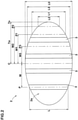
- Fig. 2 is a diagram schematically showing a ground contacting patch 2a of the tread portion 2 which occurs when the tire 1 in its standard state is put on a flat horizontal surface at a camber angle of zero, and loaded with the standard tire load.
- the ground contacting patch 2a has ground contact lengths L in the tire circumferential direction at respective positions P in the tire axial direction.
- the grooves 3 have respective groove depths d, and the groove depths d and the ground contact lengths L measured at axial positions P of the grooves 3 are in a relationship in which the respective groove depths d increase or decrease as the respective ground contact lengths L increase or decrease.
- the groove depths d of the grooves 3 are optimized, and the noise performance can be improved, while maintaining the excellent wear resistance performance.
- a crown ground contact length L0 which is the ground contact length L at the tire equator C is 1.10 to 1.50 times a shoulder ground contact length which is the ground contact length L at an axial position spaced apart from the tire equator C by 80% of a half ground contact width Tw of the ground contacting patch 2a which is the axial distance from the tire equator C to one of axially outermost end Te of the ground contacting patch 2a.
- ground contacting patch 2a is suitable for achieving both steering stability performance and wear resistance when the tire 1 is a pneumatic tire for passenger cars.
- the grooves 3 include circumferential grooves 4 (in the present embodiment, four circumferential grooves 4) extending in the tire circumferential direction, and lateral grooves 5 extending in the tire axial direction.
- the circumferential grooves 4 are an axially inner crown circumferential groove 4A and an axially outer shoulder circumferential groove 4B which are disposed on each side of the tire equator C.
- the lateral grooves 5 include shoulder lateral grooves 5A disposed in a shoulder land portion 7 defined on the axially outer side of each shoulder circumferential groove 4B.
- the groove depths d of the grooves 3 are configured so that the bottoms of the grooves 3 are located on or radially outside a virtual line VL predetermined in the meridian cross-section of the tire under its standard state with no tire load.
- the virtual line VL is for defining the maximum values of the groove depths d of the grooves 3.
- the grooves 3 in tread shoulder portions are prevented from having excessively large groove depths d. This can reduce noise caused by the grooves 3.
- the virtual line VL helps to reduce the thickness t of the tread rubber 2g of the tread portion 2, which can reduce the weight of the tire 1 and improve the fuel efficiency of the tire 1.
- the thickness t of the tread rubber 2g is defined as the distance between the radially outer surface 2b of the tread portion 2 and a tread reinforcing belt layer B disposed in the tread portion 2.
- the virtual line VL is a line positioned radially inside the radially outer surface 2b of the tread portion 2 and contacting with a reference virtual circle Vc0 and a first virtual circle Vc1.
- the reference virtual circle Vc0 is a circle having a reference radius r0 and the center positioned on the tire equatorial plane C.
- the first virtual circle Vc1 is a circle having a first radius r1 and the center positioned at a first position P1 on the radially outer surface 2b spaced apart from the tire equator C in the tire axial direction.
- the virtual line VL is uniquely-defined by the reference virtual circle Vc0 and the first virtual circle Vc1 defined on each sides in the tire axial direction of the reference virtual circle Vc0.
- SUch virtual line VL makes it unnecessary to obtain the ground contact lengths L at the respective axial positions of the grooves 3. This can reduce the time required for determining the groove depths d of the grooves 3 based on the ground contact lengths L.
- the reference radius r0 is defined based on the groove depth d of the circumferential groove 4 disposed adjacently to the tire equator C. Specifically, the reference radius r0 is set to a value equal to the radial distance measured at the tire equator C between the radially outer surface 2b and a curved line having the same radius R of curvature as the radially outer surface 2b and drawn passing through the deepest positions of the groove bottoms of the two crown circumferential grooves 4A disposed adjacently to the tire equator C on both sides thereof.
- the above-mentioned first position P1 is spaced apart from the tire equator C by an axial distance W1 of from 75% to 80% of the half ground contact width Tw in this example.
- the first position P1 is located in the above-mentioned shoulder land portion 7 axially outside the shoulder circumferential groove 4B.
- the ground contact length L at the first position P1 is referred to as the first ground contact length L1.
- the first ground contact length L1 is equal to the above-mentioned shoulder ground contact length.
- the correction coefficient ⁇ is preferably in a range from 0.5 to 1.0.
- Such correction coefficient ⁇ is useful for optimizing the groove depths d of the grooves 3, and can improve the noise performance and reduce the weight while maintaining the excellent wear resistance of the tire 1. Further, such correction coefficient ⁇ can suppress deformation of the belt layer B and improve the durability of the tire 1.
- the correction coefficient ⁇ is more preferably in a range from 0.6 to 0.9, still more preferably 0.7 to 0.8.
- the virtual line VL further contact with a second virtual circle Vc2 having a second radius r2 and the center positioned at a second position P2 on the radially outer surface 2b spaced apart from the tire equator C by an axial distance W2 of from 90% to 95% of the half ground contact width Tw.
- Such virtual line VL can be defined more accurately by the reference virtual circle Vc0, the first virtual circle Vc1, and the second virtual circle Vc2.
- the second position P2 is located in the above-mentioned shoulder land portion 7 in this example.
- the ground contact length L at the second position P2 is referred to as the second ground contact length L2.
- the virtual line VL further contact with a third virtual circle Vc3 having a third radius r3 and the center positioned at a third position P3 on the radially outer surface 2b spaced apart from the tire equator C by an axial distance W3 of from 40% to 55% of the half ground contact width Tw.
- Such virtual line VL can be defined more accurately by the reference virtual circle Vc0, the first virtual circle Vc1, the second virtual circle Vc2, and the third virtual circle Vc3.
- the third position P3 is located in a middle land portion 6 between the crown circumferential groove 4A and the shoulder circumferential groove 4B in this example.
- the ground contact length L at the third position P3 is referred to as the third ground contact length L3.
- the groove bottoms of the circumferential grooves 4 are positioned on the virtual line VL. Namely, the groove depths d of the circumferential grooves 4 are so defined.
- the virtual line VL can easily and appropriately define the groove depths d of the circumferential grooves 4.
- the groove bottoms of the lateral grooves 5 are located on the virtual line VL or radially outside the virtual line VL. Namely, the groove depths d of the lateral grooves 5 are defined in this way.
- the virtual line VL can easily and appropriately define maximum values of the groove depths d of the lateral grooves 5.
- the groove depth d of the target groove 3 is set to be equal to or less than a value of the right-hand side of the equation (4), and preferably more than 80% of this value.
- the groove depth d is set to be equal to the obtained value.
- the groove depth d is set to be equal to or less than the obtained value, and preferably more than 80% of the obtained value.
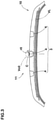
- Fig. 3 is a cross-sectional view schematically showing the tread portion 11 of a tire 10 as another embodiment taken along a meridian cross-section of the tire under its standard state. As shown, the tread portion 11 is provided with three circumferential grooves 4. In this example, one of the circumferential grooves 4 is disposed on the tire equator C.
- the reference radius r0 of the reference virtual circle Vc0 is equal to the groove depth d of the circumferential groove 4 disposed on the tire equator C.
- Fig. 4 is a flowchart showing a method for determining groove depths as an embodiment.
- this method comprises a first step S1 of determining the ground contacting patch 2a of the tread portion 2 which occurs when the tire 1 under its standard state, is put on a flat horizontal surface at a camber angle of zero and loaded with the standard tire load.
- the ground contacting patch 2a can be determined through a simulation using a computer or an experiment using an actual tire in order to obtain the accurate shape of the ground contacting patch 2a.
- the method further comprises, after the first step S1, a second step of obtaining the ground contact lengths L in the tire circumferential direction of the ground contacting patch 2a at respective axial positions P.
- the processing time can be shortened.
- the method further comprises, after the first step S2, a third step S3 of obtaining virtual radii r based on the ground contact lengths L measured at the predetermined positions P in the tire axial direction. More specifically, each virtual radius r is equal to a value obtained from the right-hand side of the above-mentioned equation (4).
- the virtual radii r may include
- the reference radius r0 and at least one of the first radius r1, the second radius r2, and the third radius r3.
- the method further comprises, after the third step S3, a fourth step S4 of defining the virtual line VL contacting with virtual circles Vc respectively having the obtained virtual radii r and centers positioned on the radially outer surface 2b of the tread portion 2 in the meridian cross-section of the tire under its standard state with no tire load.
- the method further comprises, after the fourth step S4, a fifth step S5 of determining the groove depths d of the grooves 3 so that the groove bottoms of the grooves 3 are positioned on the virtual line VL or radially outside the virtual line VL.
- the groove depths d of the grooves 3 are respectively optimized for the amounts of wear which are different from each other, depending on the positions in the tire axial direction. As a result, the tire noise caused by the grooves 3 can be reduced.
- the method of determining the groove depths of the present embodiment can improve the noise performance of the tire while maintaining the excellent wear resistance of the tire.
- pneumatic tires of size 255/65R18 were experimentally manufactured as test tires including working example tires Ex.1 and Ex.2 in which the groove depths of the circumferential grooves were determined according to the equations (1) and (2), and a comparative example tire Ref.1 in which the circumferential grooves had the same groove depths.
- test tires were tested for the wear resistance, noise performance and durability, and measured for the tire weight. Specifications of the test tires are shown in Table 1.
- test tires were mounted on all wheels of a test car (passenger car), and the test car was run for 20,000 km on dry paved roads. Then, the amount of wear was measured at different axial positions, and the amount of wear at the position where the wear was most progressed, was obtained.
- test tires were mounted on all wheels of the test car. Then, the test car was run on a road noise measuring test course, and the pass-by noise was measured.
- Each test tire in the standard state was attached to a tire drum tester, and run for 10,000 km under the standard tire load. Then, the tire was inspected to measure a total length of separation occurred at the edges of the belt layer.
Landscapes
- Engineering & Computer Science (AREA)
- Mechanical Engineering (AREA)
- Tires In General (AREA)
Abstract
Description
- The present invention relates to a tire whose tread portion is provided with tread grooves, and a method for determining groove depths.
-
Patent Document 1 below discloses a pneumatic tire, of which tread portion is provided with a plurality of main grooves extending in the tire circumferential direction, and of which wear resistance is improved by specifically defining the profile of the tread portion.
Patent Document 1:Japanese Patent Application Publication No. 2019-182339 - In the pneumatic tire of the
Patent Document 1, all the main grooves have the same groove depth. Such groove depth, namely, a relatively large groove depth, is liable to become a noise sound source. Thus, with respect to the generation of noise sound due to the deep main grooves, further improvement is desired. - The present invention was made in view of the above problems, and a primary object of the present invention is to provide a tire in which, by specifically defining groove depths, noise performance can be improved while maintaining excellent wear resistance, and a method for determining such groove depths.
- According to the present invention, a tire comprises a tread portion provided with a plurality of grooves, wherein
- ground contact lengths of a ground contacting patch measured in the tire circumferential direction at axial positions of the respective grooves, and groove depths of the respective grooves are in a relationship in which the groove depth increases or decreases as the ground contact length increases or decreases, wherein
- the ground contacting patch is that of the tread portion when the tire in its standard state is placed on a flat horizontal surface at a camber angle of zero, and loaded with a standard tire load, and
- the standard state is such that the tire is mounted on a standard wheel rim and inflated to a standard tire pressure.
- It is preferable that the groove depths of the grooves are defined so that the groove bottoms of the grooves are positioned on a virtual line or radially outside the virtual line in the meridian cross-section of the tire in the standard state with no tire load, wherein
- the virtual line extends on the radially inside of the radially outer surface of the tread portion, while contacting with a reference virtual circle and a first virtual circle,
- the reference virtual circle has a reference radius r0 and the center positioned on the tire equatorial plane, and
- the first virtual circle has a first radius r1 and the center positioned at a first position on the radially outer surface of the tread portion spaced apart from the tire equatorial plane in the tire axial direction.
- It is preferable that the first radius r1 is determined by the following equation (1):

- r0 is the reference radius,
- L0 is the ground contact length measured at the tire equator,
- L1 is the ground contact length measured at the first position, and
- α is a correction coefficient.
- It is preferable that the first position is defined on each side of the tire equator and spaced apart from the tire equator by an axial distance of from 75% to 80% of a half ground contact width which is an axial distance from the tire equator to one of axially outer ends of the ground contacting patch.
- It is preferable that the virtual line contacts with a second virtual circle having a second radius r2 and the center positioned at a second position on the radially outer surface of the tread portion spaced apart from the tire equator by an axial distance of from 90% to 95% of the half ground contact width, and the second position is defined on each side of the tire equator.
- It is preferable that the second radius r2 is determined by the following equation (2):

- r0 is the reference radius,
- L0 is the ground contact length measured at the tire equator,
- L2 is the ground contact length measured at the second position, and
- α is the correction coefficient.
- The grooves includes lateral grooves extending in the tire axial direction, and it is preferable that the lateral grooves have groove depths such that the groove bottoms of the lateral grooves are located on or radially outside the virtual line.
- The grooves include circumferential grooves extending in the tire circumferential direction, and it is preferable that the circumferential grooves have groove depths such that the groove bottoms of the circumferential grooves are positioned on the virtual line.
- According to another aspect of the present invention, a method for determining groove depths of grooves disposed in a tread portion of a tire comprises:
- a first step of determining a ground contacting patch of the tread portion which occurs when the tire under its standard state, is put on a flat horizontal surface at a camber angle of zero and loaded with a standard tire load;
- a second step of obtaining ground contact lengths in the tire circumferential direction, of the ground contacting patch at axial positions;
- a third step of obtaining virtual radii based on the ground contact lengths at predetermined positions in the tire axial direction;
- a fourth step of defining a virtual line contacting with virtual circles respectively having the obtained virtual radii and centers positioned on the radially outer surface of the tread portion in the meridian cross-section of the tire under its standard state with no tire load; and
- a fifth step of determining the groove depths of the grooves so that bottoms of the grooves are positioned on or radially outside the virtual line.
-
-
Fig. 1 is a cross-sectional view of the tread portion of a tire as an embodiment of the present invention. -
Fig. 2 is a diagram showing a ground contacting patch of the tire. -
Fig. 3 is a cross-sectional view of the tread portion of a tire as another embodiment of the present invention. -
Fig. 4 is a flowchart showing a method for determining groove depths as an embodiment of the present invention. - The present invention can be applied to various tires such as pneumatic tires and non-pneumatic tires so called airless tires, for various vehicles such as passenger cars, heavy duty vehicles (truck and bus), two-wheeled vehicles, etc.
- Taking a pneumatic tire for passenger cars as an example, embodiments of the present invention will now be described in detail in conjunction with accompanying drawings.
-
Fig. 1 shows thetread portion 2 of atire 1 as an embodiment taken along a meridian cross-section of the tire under its standard state. - Here, in the case of a pneumatic tire, the "standard state" is such that the tire is mounted on a standard wheel rim and inflate to a standard pressure but loaded with no tire load.
- In this application including specification and claims, various dimensions, positions and the like of the tire refer to those under the standard state unless otherwise noted.
- The standard wheel rim is a wheel rim officially approved or recommended for the tire by standards organizations, i.e. JATMA (Japan and Asia), T&RA (North America), ETRTO (Europe), TRAA (Australia), STRO (Scandinavia), ALAPA (Latin America), ITTAC (India) and the like which are effective in the area where the tire is manufactured, sold or used.
- The standard pressure and the standard tire load are the maximum air pressure and the maximum tire load for the tire specified by the same organization in the Air-pressure/Maximum-load Table or similar list.
- For example, the standard wheel rim is the "standard rim" specified in JATMA, the "Measuring Rim" in ETRTO, the "Design Rim" in TRA or the like. The standard pressure is the "maximum air pressure" in JATMA, the "Inflation Pressure" in ETRTO, the maximum pressure given in the "Tire Load Limits at Various Cold Inflation Pressures" table in TRA or the like. The standard load is the "maximum load capacity" in JATMA, the "Load Capacity" in ETRTO, the maximum value given in the above-mentioned table in TRA or the like.
- If there is no standard applicable to the tire, or not yet established, then a wheel rim, air pressure and tire load specified for the tire by the tire manufacturer or the like are used as the standard wheel rim, standard pressure and standard tire load.
- The
tread portion 2 has a tread surface contacting with the ground, and provided with a plurality ofgrooves 3 to expedite water drainage when running in wet conditions. -
Fig. 2 is a diagram schematically showing aground contacting patch 2a of thetread portion 2 which occurs when thetire 1 in its standard state is put on a flat horizontal surface at a camber angle of zero, and loaded with the standard tire load. As shown, theground contacting patch 2a has ground contact lengths L in the tire circumferential direction at respective positions P in the tire axial direction. - The
grooves 3 have respective groove depths d, and the groove depths d and the ground contact lengths L measured at axial positions P of thegrooves 3 are in a relationship in which the respective groove depths d increase or decrease as the respective ground contact lengths L increase or decrease. - By setting the groove depths d of the
grooves 3 in this way, decreasing rates of the groove depths d due to the progress of the tread wear can be made almost constant. - Thereby, even though the amount of wear is different depending on the axial position, the formation of an excessively large groove depth d can be prevented.
- As a result, noise sound generated by the
grooves 3 can be reduced. Thus, in thetire 1 of the present embodiment, the groove depths d of thegrooves 3 are optimized, and the noise performance can be improved, while maintaining the excellent wear resistance performance. - It is preferable that a crown ground contact length L0 which is the ground contact length L at the tire equator C is 1.10 to 1.50 times a shoulder ground contact length which is the ground contact length L at an axial position spaced apart from the tire equator C by 80% of a half ground contact width Tw of the
ground contacting patch 2a which is the axial distance from the tire equator C to one of axially outermost end Te of theground contacting patch 2a. - Such
ground contacting patch 2a is suitable for achieving both steering stability performance and wear resistance when thetire 1 is a pneumatic tire for passenger cars. - As shown in
Fig. 1 , thegrooves 3 include circumferential grooves 4 (in the present embodiment, four circumferential grooves 4) extending in the tire circumferential direction, andlateral grooves 5 extending in the tire axial direction. - In the present embodiment, the
circumferential grooves 4 are an axially innercrown circumferential groove 4A and an axially outer shouldercircumferential groove 4B which are disposed on each side of the tire equator C. - In the present embodiment, the
lateral grooves 5 includeshoulder lateral grooves 5A disposed in a shoulder land portion 7 defined on the axially outer side of each shouldercircumferential groove 4B. - In the present embodiment, the groove depths d of the
grooves 3 are configured so that the bottoms of thegrooves 3 are located on or radially outside a virtual line VL predetermined in the meridian cross-section of the tire under its standard state with no tire load. - It can be said that the virtual line VL is for defining the maximum values of the groove depths d of the
grooves 3. - The
grooves 3 in tread shoulder portions are prevented from having excessively large groove depths d. This can reduce noise caused by thegrooves 3. - The virtual line VL helps to reduce the thickness t of the
tread rubber 2g of thetread portion 2, which can reduce the weight of thetire 1 and improve the fuel efficiency of thetire 1. The thickness t of thetread rubber 2g is defined as the distance between the radiallyouter surface 2b of thetread portion 2 and a tread reinforcing belt layer B disposed in thetread portion 2. - The virtual line VL is a line positioned radially inside the radially
outer surface 2b of thetread portion 2 and contacting with a reference virtual circle Vc0 and a first virtual circle Vc1. - The reference virtual circle Vc0 is a circle having a reference radius r0 and the center positioned on the tire equatorial plane C.
- The first virtual circle Vc1 is a circle having a first radius r1 and the center positioned at a first position P1 on the radially
outer surface 2b spaced apart from the tire equator C in the tire axial direction. - The virtual line VL is uniquely-defined by the reference virtual circle Vc0 and the first virtual circle Vc1 defined on each sides in the tire axial direction of the reference virtual circle Vc0. SUch virtual line VL makes it unnecessary to obtain the ground contact lengths L at the respective axial positions of the
grooves 3. This can reduce the time required for determining the groove depths d of thegrooves 3 based on the ground contact lengths L. - In the present embodiment, the reference radius r0 is defined based on the groove depth d of the
circumferential groove 4 disposed adjacently to the tire equator C. Specifically, the reference radius r0 is set to a value equal to the radial distance measured at the tire equator C between the radiallyouter surface 2b and a curved line having the same radius R of curvature as the radiallyouter surface 2b and drawn passing through the deepest positions of the groove bottoms of the twocrown circumferential grooves 4A disposed adjacently to the tire equator C on both sides thereof. - As shown in
Figs. 1 and2 , the above-mentioned first position P1 is spaced apart from the tire equator C by an axial distance W1 of from 75% to 80% of the half ground contact width Tw in this example. - In this example, the first position P1 is located in the above-mentioned shoulder land portion 7 axially outside the shoulder
circumferential groove 4B. - The ground contact length L at the first position P1 is referred to as the first ground contact length L1.
- In the present embodiment, the first ground contact length L1 is equal to the above-mentioned shoulder ground contact length.
- It is preferable that the first radius r1 is determined by the following equation (1):

- r0 is the reference radius,
- L0 is the crown ground contact length,
- L1 is the first ground contact length, and
- α is a correction coefficient.
- Such equation (1) is useful for uniquely defining the virtual line VL.
- The correction coefficient α is preferably in a range from 0.5 to 1.0.
- Such correction coefficient α is useful for optimizing the groove depths d of the
grooves 3, and can improve the noise performance and reduce the weight while maintaining the excellent wear resistance of thetire 1. Further, such correction coefficient α can suppress deformation of the belt layer B and improve the durability of thetire 1. - From this point of view, the correction coefficient α is more preferably in a range from 0.6 to 0.9, still more preferably 0.7 to 0.8.
- It is preferable that the virtual line VL further contact with a second virtual circle Vc2 having a second radius r2 and the center positioned at a second position P2 on the radially
outer surface 2b spaced apart from the tire equator C by an axial distance W2 of from 90% to 95% of the half ground contact width Tw. - Such virtual line VL can be defined more accurately by the reference virtual circle Vc0, the first virtual circle Vc1, and the second virtual circle Vc2.
- The second position P2 is located in the above-mentioned shoulder land portion 7 in this example.
- The ground contact length L at the second position P2 is referred to as the second ground contact length L2.
- It is preferable that the second radius r2 is determined by the following equation (2):

- r0 is the reference radius,
- L0 is the crown ground contact length,
- L2 is the second ground contact length, and
- α is the correction coefficient.
- Such equation (2) is useful for uniquely defining the virtual line VL.
- It may be possible that the virtual line VL further contact with
a third virtual circle Vc3 having a third radius r3 and the center positioned at a third position P3 on the radiallyouter surface 2b spaced apart from the tire equator C by an axial distance W3 of from 40% to 55% of the half ground contact width Tw. - Such virtual line VL can be defined more accurately by the reference virtual circle Vc0, the first virtual circle Vc1, the second virtual circle Vc2, and the third virtual circle Vc3.
- The third position P3 is located in a
middle land portion 6 between thecrown circumferential groove 4A and the shouldercircumferential groove 4B in this example. - The ground contact length L at the third position P3 is referred to as the third ground contact length L3.
- It is preferable that the third radius r3 is determined by the following equation (3):

- r0 is the reference radius,
- L0 is the crown ground contact length,
- L3 is the third ground contact length, and
- α is the correction coefficient.
- Such equation (3) is useful for uniquely defining the virtual line VL.
- In the present embodiment, the groove bottoms of the
circumferential grooves 4 are positioned on the virtual line VL. Namely, the groove depths d of thecircumferential grooves 4 are so defined. Thus, the virtual line VL can easily and appropriately define the groove depths d of thecircumferential grooves 4. - In the present embodiment, the groove bottoms of the
lateral grooves 5 are located on the virtual line VL or radially outside the virtual line VL. Namely, the groove depths d of thelateral grooves 5 are defined in this way. - Thus, the virtual line VL can easily and appropriately define maximum values of the groove depths d of the
lateral grooves 5. - The maximum value for the groove depth d of a
groove 3 at an axial position can be determined based on the following equation (4) which is a generalization of the above equations (1) to (3):
- α is the correction coefficient,
- r0 is the reference radius,
- L0 is the crown ground contact length, and
- L is the ground contact length of the
ground contacting patch 2a at the axial position of thegroove 3. - Such equation (4) is useful since the groove depth d can be determined without defining the virtual line VL, in particular, when it takes time to define the virtual line VL.
- That is, given that L is a ground contact length of the ground contacting patch measured at the axial position of a
target groove 3; r0 is a given value for the depth of a circumferential groove disposed on the tire equator or most adjacently to the tire equator among the circumferential grooves; L0 is a ground contact length of the ground contacting patch measured at the tire equator, and α is a coefficient between 0.5 to 1.0, then the groove depth d of thetarget groove 3 is set to be equal to or less than a value of the right-hand side of the equation (4), and preferably more than 80% of this value. For example, when thetarget groove 3 is thecircumferential groove 4, the groove depth d is set to be equal to the obtained value. When thetarget groove 3 is thelateral groove 5, the groove depth d is set to be equal to or less than the obtained value, and preferably more than 80% of the obtained value. -
Fig. 3 is a cross-sectional view schematically showing thetread portion 11 of atire 10 as another embodiment taken along a meridian cross-section of the tire under its standard state. As shown, thetread portion 11 is provided with threecircumferential grooves 4. In this example, one of thecircumferential grooves 4 is disposed on the tire equator C. - In this embodiment, the reference radius r0 of the reference virtual circle Vc0 is equal to the groove depth d of the
circumferential groove 4 disposed on the tire equator C. - In such reference virtual circle Vc0, the definition of the reference radius r0 is clear, and the virtual line VL can be easily set.
- Next, a method for determining tread groove depths d of the
tire 1 of whichtread portion 2 is provided withgrooves 3 will be described with reference toFigs. 1 to 3 . -
Fig. 4 is a flowchart showing a method for determining groove depths as an embodiment. - As shown in
Fig. 4 , this method comprises a first step S1 of determining theground contacting patch 2a of thetread portion 2 which occurs when thetire 1 under its standard state, is put on a flat horizontal surface at a camber angle of zero and loaded with the standard tire load. - In the first step S1, the
ground contacting patch 2a can be determined through a simulation using a computer or an experiment using an actual tire in order to obtain the accurate shape of theground contacting patch 2a. - As shown in
Fig. 4 , the method further comprises, after the first step S1, a second step of obtaining the ground contact lengths L in the tire circumferential direction of theground contacting patch 2a at respective axial positions P. - In the second step S2, for example, obtained are the ground contact lengths L at a axial position of the tire equator C and at least one of the first position P1, the second position P2, and the third position P3. Thus, it is not necessary to obtain the ground contact lengths L at every axial positions P, therefore, the processing time can be shortened.
- As shown in
Fig. 4 , the method further comprises, after the first step S2, a third step S3 of obtaining virtual radii r based on the ground contact lengths L measured at the predetermined positions P in the tire axial direction. More specifically, each virtual radius r is equal to a value obtained from the right-hand side of the above-mentioned equation (4). For example, the virtual radii r may include - the reference radius r0 of the reference virtual circle Vc0,
- the first radius r1 of the first virtual circle Vc1,
- the second radius r2 of the second virtual circle Vc2, and
- the third radius r3 of the third virtual circle Vc3 are used.
- In the third step S3 in this example, there are obtained the reference radius r0 and at least one of the first radius r1, the second radius r2, and the third radius r3.
- In the present embodiment, the method further comprises, after the third step S3, a fourth step S4 of defining the virtual line VL contacting with virtual circles Vc respectively having the obtained virtual radii r and centers positioned on the radially
outer surface 2b of thetread portion 2 in the meridian cross-section of the tire under its standard state with no tire load. - In the present embodiment, the method further comprises, after the fourth step S4, a fifth step S5 of determining the groove depths d of the
grooves 3 so that the groove bottoms of thegrooves 3 are positioned on the virtual line VL or radially outside the virtual line VL. - By setting the groove depths in this way, the groove depths d of the
grooves 3 are respectively optimized for the amounts of wear which are different from each other, depending on the positions in the tire axial direction. As a result, the tire noise caused by thegrooves 3 can be reduced. - Thus, the method of determining the groove depths of the present embodiment can improve the noise performance of the tire while maintaining the excellent wear resistance of the tire.
- While detailed description has been made of preferable embodiments of the present invention, the present invention can be embodied in various forms without being limited to the illustrated embodiments.
- Based on the tire structure shown in
Fig. 1 , pneumatic tires of size 255/65R18 (Rim size 18x7.5J) were experimentally manufactured as test tires including working example tires Ex.1 and Ex.2 in which the groove depths of the circumferential grooves were determined according to the equations (1) and (2), and a comparative example tire Ref.1 in which the circumferential grooves had the same groove depths. - Then, the test tires were tested for the wear resistance, noise performance and durability, and measured for the tire weight. Specifications of the test tires are shown in Table 1.
- The test tires were mounted on all wheels of a test car (passenger car), and the test car was run for 20,000 km on dry paved roads. Then, the amount of wear was measured at different axial positions, and the amount of wear at the position where the wear was most progressed, was obtained.
- The results are indicated in Table 1 by an index based on Comparative Example tire Ref.1 being 100, wherein the larger the value, the better the wear resistance.
- The test tires were mounted on all wheels of the test car. Then, the test car was run on a road noise measuring test course, and the pass-by noise was measured.
- The results are indicated in Table 1 by an index based on Comparative Example tire Ref.1 being 100, wherein the larger the value, the better the noise performance.
- Each test tire in the standard state was attached to a tire drum tester, and run for 10,000 km under the standard tire load. Then, the tire was inspected to measure a total length of separation occurred at the edges of the belt layer.
- The results are indicated in Table 1 by an index based on Comparative Example tire Ref.1 being 100, wherein the larger the value, the better the durability.
- Each test tire was measured for the weight.
- The results are indicated in Table 1 by an index based on Comparative Example tire Ref.1 being 100, wherein the larger the value, the lighter the tire weight and the better the fuel efficiency.
Table 1 Tire Ref.1 Ex.1 Ex.2 Correction coefficient α - 0.5 1.0 Wear resistance 100 100 100 Noise performance 100 103 105 Fuel efficiency 100 103 105 Durability 100 105 103 - From the test results, it was confirmed that, according to the present invention, the noise performance and fuel efficiency are improved, while maintaining comparable wear resistance to that of the comparative example, and the durability is also improved.
- Description of the reference signs
- 1
- tire
- 2
- tread portion
- 2a
- ground contacting patch
- 3
- grooves
Claims (13)
- A tire comprising a tread portion provided with a plurality of grooves,
whereinground contact lengths of a ground contacting patch measured in the tire circumferential direction at axial positions of the respective grooves, and groove depths of the respective grooves are in a relationship in which the groove depth increases or decreases as the ground contact length increases or decreases, whereinthe ground contacting patch is that of the tread portion when the tire in its standard state is placed on a flat horizontal surface at a camber angle of zero, and loaded with a standard tire load, andthe standard state is such that the tire is mounted on a standard wheel rim and inflated to a standard tire pressure. - The tire according to claim 1, whereinthe groove depths of the grooves are defined so that the groove bottoms of the grooves are positioned on a virtual line or radially outside the virtual line in the meridian cross-section of the tire in the standard state with no tire load, whereinthe virtual line extends on the radially inside of the radially outer surface of the tread portion, while contacting with a reference virtual circle and a first virtual circle,the reference virtual circle has a reference radius r0 and the center positioned on the tire equatorial plane, andthe first virtual circle has a first radius r1 and the center positioned at a first position on the radially outer surface of the tread portion spaced apart from the tire equatorial plane in the tire axial direction.
- The tire according to claim 2, wherein
the first radius r1 is determined by the following equation (1): r0 is the reference radius,L0 is the ground contact length measured at the tire equator,L1 is the ground contact length measured at the first position, andα is a correction coefficient.
 - The tire according to claim 2 or 3, wherein
the first position is defined on each side of the tire equator and spaced apart from the tire equator by an axial distance of from 75% to 80% of a half ground contact width which is an axial distance from the tire equator to one of axially outer ends of the ground contacting patch. - The tire according to claim 4, wherein
the virtual line contacts with a second virtual circle having a second radius r2 and the center positioned at a second position on the radially outer surface of the tread portion spaced apart from the tire equator by an axial distance of from 90% to 95% of the half ground contact width, and the second position is defined on each side of the tire equator. - The tire according to claim 5, wherein
the second radius r2 is determined by the following equation (2): r0 is the reference radius,L0 is the ground contact length measured at the tire equator,L2 is the ground contact length measured at the second position, andα is the correction coefficient.
 - The tire according to claim 5 or 6, whereinthe grooves include lateral grooves extending in the tire axial direction, andthe lateral grooves have groove depths such that the groove bottoms of the lateral grooves are located on the virtual line or radially outside the virtual line.
- The tire according to claim 7, whereinthe grooves include circumferential grooves extending in the tire circumferential direction, andthe circumferential grooves have groove depths such that the groove bottoms of the circumferential grooves are positioned on the virtual line.
- The tire according to claim 1, whereinthe grooves include circumferential grooves extending in the tire circumferential direction, and lateral grooves extending in the tire axial direction, andwhen L is a ground contact length of the ground contacting patch measured at the axial position of a target groove; r0 is a given value for the depth of a circumferential groove disposed on the tire equator or most adjacently to the tire equator among circumferential grooves; L0 is a ground contact length of the ground contacting patch measured at the tire equator, and α is a coefficient between 0.5 to 1.0, then the groove depth d of the target groove is set to be equal to or less than a value of r0 x L / {L + α (LO-L)}.
- The tire according to claim 9, wherein
when the target groove is a circumferential groove, the groove depth d is set to be equal to the value of r0 x L / {L + α (LO-L)}. - The tire according to claim 9 or 10, wherein
when the target groove is a lateral groove, the groove depth d is set to be equal to or less than the value of r0 x L / {L + α (LO-L)}. - The tire according to claim 11, wherein
the groove depth d is more than 80% of the value of r0 x L / {L + α (LO-L)}. - A method for determining groove depths of grooves disposed in a tread portion of a tire comprising:a first step of determining a ground contacting patch of the tread portion which occurs when the tire under its standard state, is put on a flat horizontal surface at a camber angle of zero and loaded with a standard tire load;a second step of obtaining ground contact lengths in the tire circumferential direction, of the ground contacting patch at axial positions;a third step of obtaining virtual radii based on the ground contact lengths at predetermined positions in the tire axial direction;a fourth step of defining a virtual line contacting with virtual circles respectively having the obtained virtual radii and centers positioned on the radially outer surface of the tread portion in the meridian cross-section of the tire under its standard state with no tire load; anda fifth step of determining the groove depths of the grooves so that bottoms of the grooves are positioned on or radially outside the virtual line.
Applications Claiming Priority (1)
| Application Number | Priority Date | Filing Date | Title |
|---|---|---|---|
| JP2020152301A JP7574584B2 (en) | 2020-09-10 | 2020-09-10 | Tire and tread depth setting method |
Publications (2)
| Publication Number | Publication Date |
|---|---|
| EP3967520A1 true EP3967520A1 (en) | 2022-03-16 |
| EP3967520B1 EP3967520B1 (en) | 2024-01-03 |
Family
ID=77465830
Family Applications (1)
| Application Number | Title | Priority Date | Filing Date |
|---|---|---|---|
| EP21192695.1A Active EP3967520B1 (en) | 2020-09-10 | 2021-08-24 | Tire having tread grooves |
Country Status (4)
| Country | Link |
|---|---|
| US (1) | US20220072913A1 (en) |
| EP (1) | EP3967520B1 (en) |
| JP (1) | JP7574584B2 (en) |
| CN (1) | CN114161885A (en) |
Families Citing this family (1)
| Publication number | Priority date | Publication date | Assignee | Title |
|---|---|---|---|---|
| JP2022046321A (en) * | 2020-09-10 | 2022-03-23 | 住友ゴム工業株式会社 | Tire and groove depth setting method |
Citations (5)
| Publication number | Priority date | Publication date | Assignee | Title |
|---|---|---|---|---|
| DE102008055498A1 (en) * | 2008-12-10 | 2010-06-17 | Continental Reifen Deutschland Gmbh | Pneumatic tire for utility vehicle, has tread including peripheral grooves provided in circumferential direction, where one of grooves has depth that is preset percent greater than depth of one of remaining grooves |
| JP2014168997A (en) * | 2013-03-01 | 2014-09-18 | Bridgestone Corp | tire |
| US20160101582A1 (en) * | 2013-04-30 | 2016-04-14 | Michelin Recherche Et Technique S.A. | Treads and methods for making a retreaded tire |
| JP2019182339A (en) | 2018-04-16 | 2019-10-24 | 住友ゴム工業株式会社 | tire |
| US20190381836A1 (en) * | 2015-12-07 | 2019-12-19 | Bridgestone Corporation | Tire |
Family Cites Families (7)
| Publication number | Priority date | Publication date | Assignee | Title |
|---|---|---|---|---|
| JP4028279B2 (en) | 2002-04-08 | 2007-12-26 | 株式会社ブリヂストン | Heavy duty radial tire |
| JP2006188094A (en) * | 2004-12-28 | 2006-07-20 | Bridgestone Corp | Pneumatic radial tire |
| CN101665063A (en) * | 2008-09-01 | 2010-03-10 | 住友橡胶工业株式会社 | Rubber composition for studless tire and studless tire using the same |
| JP6494156B2 (en) * | 2013-06-24 | 2019-04-03 | 横浜ゴム株式会社 | Pneumatic tire |
| JP7006211B2 (en) * | 2017-12-06 | 2022-01-24 | 住友ゴム工業株式会社 | Pneumatic tires |
| WO2019171554A1 (en) | 2018-03-08 | 2019-09-12 | 横浜ゴム株式会社 | Pneumatic tire |
| JP2022046321A (en) * | 2020-09-10 | 2022-03-23 | 住友ゴム工業株式会社 | Tire and groove depth setting method |
-
2020
- 2020-09-10 JP JP2020152301A patent/JP7574584B2/en active Active
-
2021
- 2021-08-02 CN CN202110881241.1A patent/CN114161885A/en active Pending
- 2021-08-17 US US17/404,405 patent/US20220072913A1/en not_active Abandoned
- 2021-08-24 EP EP21192695.1A patent/EP3967520B1/en active Active
Patent Citations (5)
| Publication number | Priority date | Publication date | Assignee | Title |
|---|---|---|---|---|
| DE102008055498A1 (en) * | 2008-12-10 | 2010-06-17 | Continental Reifen Deutschland Gmbh | Pneumatic tire for utility vehicle, has tread including peripheral grooves provided in circumferential direction, where one of grooves has depth that is preset percent greater than depth of one of remaining grooves |
| JP2014168997A (en) * | 2013-03-01 | 2014-09-18 | Bridgestone Corp | tire |
| US20160101582A1 (en) * | 2013-04-30 | 2016-04-14 | Michelin Recherche Et Technique S.A. | Treads and methods for making a retreaded tire |
| US20190381836A1 (en) * | 2015-12-07 | 2019-12-19 | Bridgestone Corporation | Tire |
| JP2019182339A (en) | 2018-04-16 | 2019-10-24 | 住友ゴム工業株式会社 | tire |
Also Published As
| Publication number | Publication date |
|---|---|
| JP2022046322A (en) | 2022-03-23 |
| EP3967520B1 (en) | 2024-01-03 |
| CN114161885A (en) | 2022-03-11 |
| JP7574584B2 (en) | 2024-10-29 |
| US20220072913A1 (en) | 2022-03-10 |
Similar Documents
| Publication | Publication Date | Title |
|---|---|---|
| US8991452B2 (en) | Pneumatic tire | |
| EP3156263B1 (en) | Pneumatic tire | |
| EP3156261A1 (en) | Pneumatic tire | |
| US10486472B2 (en) | Pneumatic tire | |
| US7918256B2 (en) | Heavy duty tire having ground contacting face at 70% and 100% maximum tire load | |
| EP2639084A1 (en) | Pneumatic tire | |
| EP2952362A1 (en) | Pneumatic tire | |
| KR102377656B1 (en) | Pneumatic tire | |
| EP3042792A1 (en) | Pneumatic tire | |
| EP3501852A1 (en) | Tyre | |
| US10953701B2 (en) | Tire | |
| EP2777951A1 (en) | Pneumatic tire | |
| US11104182B2 (en) | Tire | |
| EP3332991A1 (en) | Pneumatic tire | |
| US20190308465A1 (en) | Tyre | |
| EP3744537B1 (en) | Tire | |
| US20220194133A1 (en) | Tire | |
| EP3967521B1 (en) | Tire having tread grooves and method for configuring groove depths | |
| EP3967520B1 (en) | Tire having tread grooves | |
| EP4015244B1 (en) | Tire | |
| EP3666552B1 (en) | Tyre |
Legal Events
| Date | Code | Title | Description |
|---|---|---|---|
| PUAI | Public reference made under article 153(3) epc to a published international application that has entered the european phase |
Free format text: ORIGINAL CODE: 0009012 |
|
| STAA | Information on the status of an ep patent application or granted ep patent |
Free format text: STATUS: THE APPLICATION HAS BEEN PUBLISHED |
|
| AK | Designated contracting states |
Kind code of ref document: A1 Designated state(s): AL AT BE BG CH CY CZ DE DK EE ES FI FR GB GR HR HU IE IS IT LI LT LU LV MC MK MT NL NO PL PT RO RS SE SI SK SM TR |
|
| STAA | Information on the status of an ep patent application or granted ep patent |
Free format text: STATUS: REQUEST FOR EXAMINATION WAS MADE |
|
| 17P | Request for examination filed |
Effective date: 20220610 |
|
| RBV | Designated contracting states (corrected) |
Designated state(s): AL AT BE BG CH CY CZ DE DK EE ES FI FR GB GR HR HU IE IS IT LI LT LU LV MC MK MT NL NO PL PT RO RS SE SI SK SM TR |
|
| STAA | Information on the status of an ep patent application or granted ep patent |
Free format text: STATUS: EXAMINATION IS IN PROGRESS |
|
| 17Q | First examination report despatched |
Effective date: 20230406 |
|
| P01 | Opt-out of the competence of the unified patent court (upc) registered |
Effective date: 20230510 |
|
| GRAP | Despatch of communication of intention to grant a patent |
Free format text: ORIGINAL CODE: EPIDOSNIGR1 |
|
| STAA | Information on the status of an ep patent application or granted ep patent |
Free format text: STATUS: GRANT OF PATENT IS INTENDED |
|
| RIC1 | Information provided on ipc code assigned before grant |
Ipc: B60C 99/00 20060101ALN20230925BHEP Ipc: B60C 11/03 20060101AFI20230925BHEP |
|
| GRAS | Grant fee paid |
Free format text: ORIGINAL CODE: EPIDOSNIGR3 |
|
| INTG | Intention to grant announced |
Effective date: 20231030 |
|
| GRAA | (expected) grant |
Free format text: ORIGINAL CODE: 0009210 |
|
| STAA | Information on the status of an ep patent application or granted ep patent |
Free format text: STATUS: THE PATENT HAS BEEN GRANTED |
|
| AK | Designated contracting states |
Kind code of ref document: B1 Designated state(s): AL AT BE BG CH CY CZ DE DK EE ES FI FR GB GR HR HU IE IS IT LI LT LU LV MC MK MT NL NO PL PT RO RS SE SI SK SM TR |
|
| REG | Reference to a national code |
Ref country code: GB Ref legal event code: FG4D |
|
| REG | Reference to a national code |
Ref country code: CH Ref legal event code: EP |
|
| REG | Reference to a national code |
Ref country code: DE Ref legal event code: R096 Ref document number: 602021008257 Country of ref document: DE |
|
| REG | Reference to a national code |
Ref country code: IE Ref legal event code: FG4D |
|
| REG | Reference to a national code |
Ref country code: LT Ref legal event code: MG9D |
|
| PG25 | Lapsed in a contracting state [announced via postgrant information from national office to epo] |
Ref country code: ES Free format text: LAPSE BECAUSE OF FAILURE TO SUBMIT A TRANSLATION OF THE DESCRIPTION OR TO PAY THE FEE WITHIN THE PRESCRIBED TIME-LIMIT Effective date: 20240103 |
|
| PG25 | Lapsed in a contracting state [announced via postgrant information from national office to epo] |
Ref country code: ES Free format text: LAPSE BECAUSE OF FAILURE TO SUBMIT A TRANSLATION OF THE DESCRIPTION OR TO PAY THE FEE WITHIN THE PRESCRIBED TIME-LIMIT Effective date: 20240103 |
|
| REG | Reference to a national code |
Ref country code: NL Ref legal event code: MP Effective date: 20240103 |
|
| REG | Reference to a national code |
Ref country code: AT Ref legal event code: MK05 Ref document number: 1646455 Country of ref document: AT Kind code of ref document: T Effective date: 20240103 |
|
| PG25 | Lapsed in a contracting state [announced via postgrant information from national office to epo] |
Ref country code: NL Free format text: LAPSE BECAUSE OF FAILURE TO SUBMIT A TRANSLATION OF THE DESCRIPTION OR TO PAY THE FEE WITHIN THE PRESCRIBED TIME-LIMIT Effective date: 20240103 |
|
| PG25 | Lapsed in a contracting state [announced via postgrant information from national office to epo] |
Ref country code: NL Free format text: LAPSE BECAUSE OF FAILURE TO SUBMIT A TRANSLATION OF THE DESCRIPTION OR TO PAY THE FEE WITHIN THE PRESCRIBED TIME-LIMIT Effective date: 20240103 |
|
| PG25 | Lapsed in a contracting state [announced via postgrant information from national office to epo] |
Ref country code: IS Free format text: LAPSE BECAUSE OF FAILURE TO SUBMIT A TRANSLATION OF THE DESCRIPTION OR TO PAY THE FEE WITHIN THE PRESCRIBED TIME-LIMIT Effective date: 20240503 |
|
| PG25 | Lapsed in a contracting state [announced via postgrant information from national office to epo] |
Ref country code: LT Free format text: LAPSE BECAUSE OF FAILURE TO SUBMIT A TRANSLATION OF THE DESCRIPTION OR TO PAY THE FEE WITHIN THE PRESCRIBED TIME-LIMIT Effective date: 20240103 |
|
| PG25 | Lapsed in a contracting state [announced via postgrant information from national office to epo] |
Ref country code: GR Free format text: LAPSE BECAUSE OF FAILURE TO SUBMIT A TRANSLATION OF THE DESCRIPTION OR TO PAY THE FEE WITHIN THE PRESCRIBED TIME-LIMIT Effective date: 20240404 |
|
| PG25 | Lapsed in a contracting state [announced via postgrant information from national office to epo] |
Ref country code: RS Free format text: LAPSE BECAUSE OF FAILURE TO SUBMIT A TRANSLATION OF THE DESCRIPTION OR TO PAY THE FEE WITHIN THE PRESCRIBED TIME-LIMIT Effective date: 20240403 Ref country code: HR Free format text: LAPSE BECAUSE OF FAILURE TO SUBMIT A TRANSLATION OF THE DESCRIPTION OR TO PAY THE FEE WITHIN THE PRESCRIBED TIME-LIMIT Effective date: 20240103 |
|
| PG25 | Lapsed in a contracting state [announced via postgrant information from national office to epo] |
Ref country code: AT Free format text: LAPSE BECAUSE OF FAILURE TO SUBMIT A TRANSLATION OF THE DESCRIPTION OR TO PAY THE FEE WITHIN THE PRESCRIBED TIME-LIMIT Effective date: 20240103 Ref country code: CZ Free format text: LAPSE BECAUSE OF FAILURE TO SUBMIT A TRANSLATION OF THE DESCRIPTION OR TO PAY THE FEE WITHIN THE PRESCRIBED TIME-LIMIT Effective date: 20240103 |
|
| PG25 | Lapsed in a contracting state [announced via postgrant information from national office to epo] |
Ref country code: RS Free format text: LAPSE BECAUSE OF FAILURE TO SUBMIT A TRANSLATION OF THE DESCRIPTION OR TO PAY THE FEE WITHIN THE PRESCRIBED TIME-LIMIT Effective date: 20240403 Ref country code: NO Free format text: LAPSE BECAUSE OF FAILURE TO SUBMIT A TRANSLATION OF THE DESCRIPTION OR TO PAY THE FEE WITHIN THE PRESCRIBED TIME-LIMIT Effective date: 20240403 Ref country code: LT Free format text: LAPSE BECAUSE OF FAILURE TO SUBMIT A TRANSLATION OF THE DESCRIPTION OR TO PAY THE FEE WITHIN THE PRESCRIBED TIME-LIMIT Effective date: 20240103 Ref country code: IS Free format text: LAPSE BECAUSE OF FAILURE TO SUBMIT A TRANSLATION OF THE DESCRIPTION OR TO PAY THE FEE WITHIN THE PRESCRIBED TIME-LIMIT Effective date: 20240503 Ref country code: HR Free format text: LAPSE BECAUSE OF FAILURE TO SUBMIT A TRANSLATION OF THE DESCRIPTION OR TO PAY THE FEE WITHIN THE PRESCRIBED TIME-LIMIT Effective date: 20240103 Ref country code: GR Free format text: LAPSE BECAUSE OF FAILURE TO SUBMIT A TRANSLATION OF THE DESCRIPTION OR TO PAY THE FEE WITHIN THE PRESCRIBED TIME-LIMIT Effective date: 20240404 Ref country code: CZ Free format text: LAPSE BECAUSE OF FAILURE TO SUBMIT A TRANSLATION OF THE DESCRIPTION OR TO PAY THE FEE WITHIN THE PRESCRIBED TIME-LIMIT Effective date: 20240103 Ref country code: BG Free format text: LAPSE BECAUSE OF FAILURE TO SUBMIT A TRANSLATION OF THE DESCRIPTION OR TO PAY THE FEE WITHIN THE PRESCRIBED TIME-LIMIT Effective date: 20240103 Ref country code: AT Free format text: LAPSE BECAUSE OF FAILURE TO SUBMIT A TRANSLATION OF THE DESCRIPTION OR TO PAY THE FEE WITHIN THE PRESCRIBED TIME-LIMIT Effective date: 20240103 |
|
| PG25 | Lapsed in a contracting state [announced via postgrant information from national office to epo] |
Ref country code: PL Free format text: LAPSE BECAUSE OF FAILURE TO SUBMIT A TRANSLATION OF THE DESCRIPTION OR TO PAY THE FEE WITHIN THE PRESCRIBED TIME-LIMIT Effective date: 20240103 Ref country code: PT Free format text: LAPSE BECAUSE OF FAILURE TO SUBMIT A TRANSLATION OF THE DESCRIPTION OR TO PAY THE FEE WITHIN THE PRESCRIBED TIME-LIMIT Effective date: 20240503 |
|
| PG25 | Lapsed in a contracting state [announced via postgrant information from national office to epo] |
Ref country code: SE Free format text: LAPSE BECAUSE OF FAILURE TO SUBMIT A TRANSLATION OF THE DESCRIPTION OR TO PAY THE FEE WITHIN THE PRESCRIBED TIME-LIMIT Effective date: 20240103 Ref country code: PT Free format text: LAPSE BECAUSE OF FAILURE TO SUBMIT A TRANSLATION OF THE DESCRIPTION OR TO PAY THE FEE WITHIN THE PRESCRIBED TIME-LIMIT Effective date: 20240503 Ref country code: PL Free format text: LAPSE BECAUSE OF FAILURE TO SUBMIT A TRANSLATION OF THE DESCRIPTION OR TO PAY THE FEE WITHIN THE PRESCRIBED TIME-LIMIT Effective date: 20240103 Ref country code: LV Free format text: LAPSE BECAUSE OF FAILURE TO SUBMIT A TRANSLATION OF THE DESCRIPTION OR TO PAY THE FEE WITHIN THE PRESCRIBED TIME-LIMIT Effective date: 20240103 |
|
| REG | Reference to a national code |
Ref country code: DE Ref legal event code: R097 Ref document number: 602021008257 Country of ref document: DE |
|
| PG25 | Lapsed in a contracting state [announced via postgrant information from national office to epo] |
Ref country code: DK Free format text: LAPSE BECAUSE OF FAILURE TO SUBMIT A TRANSLATION OF THE DESCRIPTION OR TO PAY THE FEE WITHIN THE PRESCRIBED TIME-LIMIT Effective date: 20240103 |
|
| PG25 | Lapsed in a contracting state [announced via postgrant information from national office to epo] |
Ref country code: SM Free format text: LAPSE BECAUSE OF FAILURE TO SUBMIT A TRANSLATION OF THE DESCRIPTION OR TO PAY THE FEE WITHIN THE PRESCRIBED TIME-LIMIT Effective date: 20240103 |
|
| PG25 | Lapsed in a contracting state [announced via postgrant information from national office to epo] |
Ref country code: EE Free format text: LAPSE BECAUSE OF FAILURE TO SUBMIT A TRANSLATION OF THE DESCRIPTION OR TO PAY THE FEE WITHIN THE PRESCRIBED TIME-LIMIT Effective date: 20240103 |
|
| PG25 | Lapsed in a contracting state [announced via postgrant information from national office to epo] |
Ref country code: SK Free format text: LAPSE BECAUSE OF FAILURE TO SUBMIT A TRANSLATION OF THE DESCRIPTION OR TO PAY THE FEE WITHIN THE PRESCRIBED TIME-LIMIT Effective date: 20240103 |
|
| PG25 | Lapsed in a contracting state [announced via postgrant information from national office to epo] |
Ref country code: SM Free format text: LAPSE BECAUSE OF FAILURE TO SUBMIT A TRANSLATION OF THE DESCRIPTION OR TO PAY THE FEE WITHIN THE PRESCRIBED TIME-LIMIT Effective date: 20240103 Ref country code: SK Free format text: LAPSE BECAUSE OF FAILURE TO SUBMIT A TRANSLATION OF THE DESCRIPTION OR TO PAY THE FEE WITHIN THE PRESCRIBED TIME-LIMIT Effective date: 20240103 Ref country code: RO Free format text: LAPSE BECAUSE OF FAILURE TO SUBMIT A TRANSLATION OF THE DESCRIPTION OR TO PAY THE FEE WITHIN THE PRESCRIBED TIME-LIMIT Effective date: 20240103 Ref country code: EE Free format text: LAPSE BECAUSE OF FAILURE TO SUBMIT A TRANSLATION OF THE DESCRIPTION OR TO PAY THE FEE WITHIN THE PRESCRIBED TIME-LIMIT Effective date: 20240103 Ref country code: DK Free format text: LAPSE BECAUSE OF FAILURE TO SUBMIT A TRANSLATION OF THE DESCRIPTION OR TO PAY THE FEE WITHIN THE PRESCRIBED TIME-LIMIT Effective date: 20240103 |
|
| PLBE | No opposition filed within time limit |
Free format text: ORIGINAL CODE: 0009261 |
|
| STAA | Information on the status of an ep patent application or granted ep patent |
Free format text: STATUS: NO OPPOSITION FILED WITHIN TIME LIMIT |
|
| PG25 | Lapsed in a contracting state [announced via postgrant information from national office to epo] |
Ref country code: IT Free format text: LAPSE BECAUSE OF FAILURE TO SUBMIT A TRANSLATION OF THE DESCRIPTION OR TO PAY THE FEE WITHIN THE PRESCRIBED TIME-LIMIT Effective date: 20240103 |
|
| 26N | No opposition filed |
Effective date: 20241007 |
|
| PG25 | Lapsed in a contracting state [announced via postgrant information from national office to epo] |
Ref country code: IT Free format text: LAPSE BECAUSE OF FAILURE TO SUBMIT A TRANSLATION OF THE DESCRIPTION OR TO PAY THE FEE WITHIN THE PRESCRIBED TIME-LIMIT Effective date: 20240103 |
|
| REG | Reference to a national code |
Ref country code: CH Ref legal event code: PL |
|
| PG25 | Lapsed in a contracting state [announced via postgrant information from national office to epo] |
Ref country code: LU Free format text: LAPSE BECAUSE OF NON-PAYMENT OF DUE FEES Effective date: 20240824 |
|
| PG25 | Lapsed in a contracting state [announced via postgrant information from national office to epo] |
Ref country code: MC Free format text: LAPSE BECAUSE OF FAILURE TO SUBMIT A TRANSLATION OF THE DESCRIPTION OR TO PAY THE FEE WITHIN THE PRESCRIBED TIME-LIMIT Effective date: 20240103 Ref country code: SI Free format text: LAPSE BECAUSE OF FAILURE TO SUBMIT A TRANSLATION OF THE DESCRIPTION OR TO PAY THE FEE WITHIN THE PRESCRIBED TIME-LIMIT Effective date: 20240103 Ref country code: CH Free format text: LAPSE BECAUSE OF NON-PAYMENT OF DUE FEES Effective date: 20240831 |
|
| REG | Reference to a national code |
Ref country code: BE Ref legal event code: MM Effective date: 20240831 |
|
| PG25 | Lapsed in a contracting state [announced via postgrant information from national office to epo] |
Ref country code: BE Free format text: LAPSE BECAUSE OF NON-PAYMENT OF DUE FEES Effective date: 20240831 |
|
| PG25 | Lapsed in a contracting state [announced via postgrant information from national office to epo] |
Ref country code: IE Free format text: LAPSE BECAUSE OF NON-PAYMENT OF DUE FEES Effective date: 20240824 |
|
| PG25 | Lapsed in a contracting state [announced via postgrant information from national office to epo] |
Ref country code: FI Free format text: LAPSE BECAUSE OF FAILURE TO SUBMIT A TRANSLATION OF THE DESCRIPTION OR TO PAY THE FEE WITHIN THE PRESCRIBED TIME-LIMIT Effective date: 20240103 |
|
| PGFP | Annual fee paid to national office [announced via postgrant information from national office to epo] |
Ref country code: DE Payment date: 20250702 Year of fee payment: 5 |
|
| PGFP | Annual fee paid to national office [announced via postgrant information from national office to epo] |
Ref country code: FR Payment date: 20250703 Year of fee payment: 5 |
|
| PG25 | Lapsed in a contracting state [announced via postgrant information from national office to epo] |
Ref country code: CY Free format text: LAPSE BECAUSE OF FAILURE TO SUBMIT A TRANSLATION OF THE DESCRIPTION OR TO PAY THE FEE WITHIN THE PRESCRIBED TIME-LIMIT; INVALID AB INITIO Effective date: 20210824 |
|
| PG25 | Lapsed in a contracting state [announced via postgrant information from national office to epo] |
Ref country code: HU Free format text: LAPSE BECAUSE OF FAILURE TO SUBMIT A TRANSLATION OF THE DESCRIPTION OR TO PAY THE FEE WITHIN THE PRESCRIBED TIME-LIMIT; INVALID AB INITIO Effective date: 20210824 |