EP3967470B1 - Prepreg continuous production device and method therefor - Google Patents
Prepreg continuous production device and method therefor Download PDFInfo
- Publication number
- EP3967470B1 EP3967470B1 EP20805329.8A EP20805329A EP3967470B1 EP 3967470 B1 EP3967470 B1 EP 3967470B1 EP 20805329 A EP20805329 A EP 20805329A EP 3967470 B1 EP3967470 B1 EP 3967470B1
- Authority
- EP
- European Patent Office
- Prior art keywords
- matrix resin
- cloth
- pair
- heating rollers
- prepreg
- Prior art date
- Legal status (The legal status is an assumption and is not a legal conclusion. Google has not performed a legal analysis and makes no representation as to the accuracy of the status listed.)
- Active
Links
Images




Classifications
-
- B—PERFORMING OPERATIONS; TRANSPORTING
- B29—WORKING OF PLASTICS; WORKING OF SUBSTANCES IN A PLASTIC STATE IN GENERAL
- B29C—SHAPING OR JOINING OF PLASTICS; SHAPING OF MATERIAL IN A PLASTIC STATE, NOT OTHERWISE PROVIDED FOR; AFTER-TREATMENT OF THE SHAPED PRODUCTS, e.g. REPAIRING
- B29C70/00—Shaping composites, i.e. plastics material comprising reinforcements, fillers or preformed parts, e.g. inserts
- B29C70/04—Shaping composites, i.e. plastics material comprising reinforcements, fillers or preformed parts, e.g. inserts comprising reinforcements only, e.g. self-reinforcing plastics
- B29C70/28—Shaping operations therefor
- B29C70/40—Shaping or impregnating by compression not applied
- B29C70/50—Shaping or impregnating by compression not applied for producing articles of indefinite length, e.g. prepregs, sheet moulding compounds [SMC] or cross moulding compounds [XMC]
- B29C70/504—Shaping or impregnating by compression not applied for producing articles of indefinite length, e.g. prepregs, sheet moulding compounds [SMC] or cross moulding compounds [XMC] using rollers or pressure bands
-
- B—PERFORMING OPERATIONS; TRANSPORTING
- B29—WORKING OF PLASTICS; WORKING OF SUBSTANCES IN A PLASTIC STATE IN GENERAL
- B29B—PREPARATION OR PRETREATMENT OF THE MATERIAL TO BE SHAPED; MAKING GRANULES OR PREFORMS; RECOVERY OF PLASTICS OR OTHER CONSTITUENTS OF WASTE MATERIAL CONTAINING PLASTICS
- B29B15/00—Pretreatment of the material to be shaped, not covered by groups B29B7/00 - B29B13/00
- B29B15/08—Pretreatment of the material to be shaped, not covered by groups B29B7/00 - B29B13/00 of reinforcements or fillers
- B29B15/10—Coating or impregnating independently of the moulding or shaping step
- B29B15/12—Coating or impregnating independently of the moulding or shaping step of reinforcements of indefinite length
- B29B15/122—Coating or impregnating independently of the moulding or shaping step of reinforcements of indefinite length with a matrix in liquid form, e.g. as melt, solution or latex
-
- B—PERFORMING OPERATIONS; TRANSPORTING
- B29—WORKING OF PLASTICS; WORKING OF SUBSTANCES IN A PLASTIC STATE IN GENERAL
- B29C—SHAPING OR JOINING OF PLASTICS; SHAPING OF MATERIAL IN A PLASTIC STATE, NOT OTHERWISE PROVIDED FOR; AFTER-TREATMENT OF THE SHAPED PRODUCTS, e.g. REPAIRING
- B29C33/00—Moulds or cores; Details thereof or accessories therefor
- B29C33/56—Coatings, e.g. enameled or galvanised; Releasing, lubricating or separating agents
- B29C33/68—Release sheets
-
- B—PERFORMING OPERATIONS; TRANSPORTING
- B29—WORKING OF PLASTICS; WORKING OF SUBSTANCES IN A PLASTIC STATE IN GENERAL
- B29C—SHAPING OR JOINING OF PLASTICS; SHAPING OF MATERIAL IN A PLASTIC STATE, NOT OTHERWISE PROVIDED FOR; AFTER-TREATMENT OF THE SHAPED PRODUCTS, e.g. REPAIRING
- B29C70/00—Shaping composites, i.e. plastics material comprising reinforcements, fillers or preformed parts, e.g. inserts
- B29C70/04—Shaping composites, i.e. plastics material comprising reinforcements, fillers or preformed parts, e.g. inserts comprising reinforcements only, e.g. self-reinforcing plastics
- B29C70/28—Shaping operations therefor
- B29C70/54—Component parts, details or accessories; Auxiliary operations, e.g. feeding or storage of prepregs or SMC after impregnation or during ageing
- B29C70/546—Measures for feeding or distributing the matrix material in the reinforcing structure
-
- B—PERFORMING OPERATIONS; TRANSPORTING
- B29—WORKING OF PLASTICS; WORKING OF SUBSTANCES IN A PLASTIC STATE IN GENERAL
- B29K—INDEXING SCHEME ASSOCIATED WITH SUBCLASSES B29B, B29C OR B29D, RELATING TO MOULDING MATERIALS OR TO MATERIALS FOR MOULDS, REINFORCEMENTS, FILLERS OR PREFORMED PARTS, e.g. INSERTS
- B29K2105/00—Condition, form or state of moulded material or of the material to be shaped
- B29K2105/0094—Condition, form or state of moulded material or of the material to be shaped having particular viscosity
-
- B—PERFORMING OPERATIONS; TRANSPORTING
- B29—WORKING OF PLASTICS; WORKING OF SUBSTANCES IN A PLASTIC STATE IN GENERAL
- B29K—INDEXING SCHEME ASSOCIATED WITH SUBCLASSES B29B, B29C OR B29D, RELATING TO MOULDING MATERIALS OR TO MATERIALS FOR MOULDS, REINFORCEMENTS, FILLERS OR PREFORMED PARTS, e.g. INSERTS
- B29K2105/00—Condition, form or state of moulded material or of the material to be shaped
- B29K2105/06—Condition, form or state of moulded material or of the material to be shaped containing reinforcements, fillers or inserts
- B29K2105/08—Condition, form or state of moulded material or of the material to be shaped containing reinforcements, fillers or inserts of continuous length, e.g. cords, rovings, mats, fabrics, strands or yarns
- B29K2105/0872—Prepregs
- B29K2105/089—Prepregs fabric
Definitions
- the present invention relates to a prepreg continuous production device and a method therefor by a hot melt method.
- the prepreg is a plastic molding material obtained by impregnating a fibrous reinforcement material, such as glass cloth or carbon fibers (hereinafter referred to as "fibrous base material"), with resin, and then heating or drying the resultant fibrous base material into a semi-cured state.
- a fibrous reinforcement material such as glass cloth or carbon fibers
- the prepreg is required as an intermediate material thereof.
- cloth such as a woven fabric, is used, for example.
- examples of a method for producing the prepreg include a hot melt method and a solvent method.
- the hot melt method includes placing a sheet-like fibrous base material between release paper sheets, to which a matrix resin has been applied, and then heating them in an overlaid state to thereby reduce the viscosity of the matrix resin and impregnate the fibrous base material with the matrix resin.
- the solvent method includes adding a solvent to the matrix resin to reduce the viscosity of the resin, and then impregnating the fibrous base material with the resultant resin, and then evaporating the solvent using a dryer or the like.
- the method for producing the prepreg by the hot melt method is disclosed in PTL 1, for example.
- the matrix resin is applied to each surface of the fibrous base material.
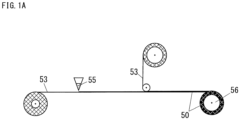
- FIG. 1A is an explanatory view illustrating a first step of a method for producing a prepreg 52 by a conventional hot melt method.
- the first step is a step of applying a matrix resin 55 onto a release paper sheet or release film 53 in the shape of a thin film, and then covering the matrix resin 55 with another release paper sheet or release film 53 to create a resin film 50.
- the resin film 50 has a configuration in which two release paper sheets or release films 53 hold the matrix resin 55 therebetween and is wound around a roll 56.
- the film thickness of the resin film 50 is adjusted according to the required amount of the matrix resin 55 in the prepreg 52.
- FIG. 1B is an explanatory view illustrating a second step of the method for producing the prepreg 52 by the conventional hot melt method.
- a fibrous base material 54 is impregnated with the matrix resin 55 from both surfaces thereof as illustrated in FIG. 1B .
- the second step of PTL 1 uses two rolls of the resin film 50 created in the first step.
- the release paper sheets or release films 53 on the side facing the fibrous base material 54 of the two rolls of the resin films 50 are first peeled off, and then the fibrous base material 54 is held and stuck between the resin films 50. Thereafter, the resultant substance is heated on a hot plate 61 to reduce the viscosity of the matrix resin 55. By subsequent heating and pressurization with rollers 62, the fibrous base material 54 is impregnated with the matrix resin 55 to complete the prepreg 52.
- PTL2 discloses a prepreg production device and a prepreg continuous production method. Specifically, PTL2 discloses to apply a pool of molten resin in a gap portion between a pair of heated rollers and passing a continuous reinforcement fiber through the pool of molten resin to impregnate the fiber with the resin. PTL2 further suggests to adjust the gap between the rollers to control the amount of resin applied to the fiber.
- the method for producing the prepreg 52 by the conventional hot melt method has required the two steps of the first step of producing the resin film 50 and the second step of impregnating the fibrous base material 54 with the matrix resin 55 of the resin film 50, and thus the productivity has not been good.
- the conventional hot melt method When a low viscosity resin is used for the conventional hot melt method, the resin cannot be left on only one release paper sheet or release film 53 in peeling off the resin from the release paper sheet or release films 53 in the second step, so that the film thickness is not fixed. Therefore, the conventional hot melt method has not been applicable to the impregnation of the fibrous base material 54 with the low viscosity resin.
- the present invention has been conceived in order to solve the above-described problems. More specifically, it is an object of the present invention to provide a prepreg continuous production device and a method therefor by a hot melt method not requiring a step of creating a resin film and usable even for a low viscosity resin.
- the present invention provides a prepreg continuous production device according to the subject-matter of the independent claim 1.
- the present invention also provides a prepreg continuous production method according to the subject-matter of the independent claim 6.
- the pair of release sheets and the cloth arranged therebetween pass through the gap portion of the pair of heating rollers and the matrix resin is supplied to be accumulated above the gap portion and between the pair of release sheets.
- the present invention can perform the step of making the matrix resin adhere to the cloth, the adjustment of the adhesion amount of the matrix resin, and the step of overlaying the release sheet on each surface of the cloth at a time in the gap portion of the heating rollers. Therefore, the present invention can omit a step of producing a resin film, which was required in the conventional hot melt method.
- the present invention can produce a prepreg in continuous one step, and therefore can improve the productivity and the production workability.
- the present invention makes the matrix resin adhere to the cloth by immersing the cloth in the matrix resin accumulated above the gap portion. Therefore, the present invention can use, for the production of the prepreg, even the matrix resin which has been incapable of producing a resin film due to its low viscosity at room temperature or a low temperature and unsuitable for the conventional hot melt method.
- FIG. 2 is an explanatory view of a prepreg continuous production device 1 of a first embodiment.
- This embodiment is an embodiment of making a matrix resin 5 adhere to one surface of cloth 4.
- the prepreg continuous production device 1 (hereinafter referred to as "continuous production device 1") is a device of producing a prepreg 10 in continuous one step of a hot melt method using a matrix resin 5.
- the continuous production device 1 includes a pair of heating rollers 2, a pair of release sheet reels 13, a cloth reel 14, and a resin supply device 8.
- the continuous production device 1 When using the continuous production device 1, two release sheets 3, the cloth 4, and the matrix resin 5 are charged into a gap portion 2b positioned in a clearance between the pair of heating rollers 2. Thus, the continuous production device 1 can produce one in which the matrix resin 5 adheres to the cloth 4 and each surface thereof is covered with the release sheet 3 at a time.
- the matrix resin 5 is a thermosetting resin or a thermoplastic resin or a mixture thereof and has a characteristic that the viscosity decreases when heated once.
- the matrix resin 5 of this embodiment is preferably a solvent-free resin, but may be a matrix resin containing a solvent, depending on the requirements of the prepreg 10.
- the matrix resin 5 is first charged into the gap portion 2b between the pair of heating rollers 2.
- the pair of heating rollers 2 are adjacent to each other and form one set and rotate around axes of rotation 2a extending horizontally and parallel to each other.
- a pair of release sheets 3 and the cloth 4 are placed over peripheral surfaces 2c of the heating rollers 2 from above to below through the gap portion 2b.
- the resin supply device 8 charges the matrix resin 5 between the release sheets 3 and the cloth 4.
- the resin supply device 8 supplies the matrix resin 5 to be accumulated above the gap portion 2b and between the pair of release sheets 3.
- the resin supply device 8 may be a resin tank 8a and a pump 8b as illustrated in this figure.
- the matrix resin 5 is transferred from the resin tank 8a by the pump 8b or the like to be charged into the gap portion 2b.
- the viscosity of the matrix resin 5 above the gap portion 2b is preferably 0.5 Pa ⁇ s or more and 100 Pa ⁇ s or less. This is because, when the viscosity of the matrix resin 5 above the gap portion 2b is less than 0.5 Pa ⁇ s, the matrix resin 5 tends to flow downward in the vertical direction from the gap portion 2b through the cloth 4, making it difficult to control the progress speed of the production line and adjust the adhesion amount of the matrix resin 5.
- the heating rollers 2 in the case of using the matrix resin 5 having a high viscosity at room temperature or a low temperature can heat the matrix resin 5 until the viscosity of the matrix resin 5 reaches 0.5 Pa ⁇ s or more and 100 Pa ⁇ s or less.
- the viscosity of the matrix resin 5 above the gap portion 2b is particularly preferably 0.5 Pa ⁇ s or more and 10 Pa ⁇ s or less.
- the viscosity of the matrix resin 5 above the gap portion 2b is particularly preferably 10 Pa ⁇ s or less, because, when the viscosity is larger than 10 Pa ⁇ s, it takes time to feed the matrix resin 5 downward by the heating rollers 2, decreasing the productivity of the prepreg 10.
- the heating rollers 2 are also preferably configured to be able to control the distance of a clearance of the gap portion 2b.
- the heating rollers 2 may have an actuator 15 moving one heating roller 2 horizontally toward the other heating roller 2 together with a motor 2d rotating the axis of rotation 2a of one heating roller 2.
- a control device 16 is connected to the actuator 15 and the control device 16 drives the actuator 15 to adjust the distance of the clearance of the gap portion 2b.
- the actuator 15 is not limited to the configuration illustrated in this figure and may also be provided in the heating roller 2 around which the cloth 4 is wound or may be provided in both the heating rollers 2.
- the heating roller 2 around which the cloth 4 is wound may be either the right or left heating roller 2 in this figure.
- the release sheet reels 13 are devices capable of rewinding the release sheets 3 toward the peripheral surfaces 2c of the pair of heating rollers 2.
- One release sheet reel 13 is provided for one heating roller 2, forming one pair in total. It is preferable that the release sheet reels 13 have a braking mechanism of stopping the rotation of the release sheets 3 in addition to the rewinding of the release sheets 3 by generating back tension in the release sheets 3.
- the release sheets 3 are film-like artifacts which are used to hold the cloth 4 and the matrix resin 5 from both surfaces.
- a pair of release sheets 3 (2 rolls) is used in the continuous production device 1. As illustrated in this figure, one release sheet 3 is arranged for one heating roller 2 and passes up to down through the gap portion 2b of the heating roller 2.
- the release sheets 3 may be, for example, release films or release paper sheets. It is preferable to properly use the release film or the release paper sheet depending on the temperature of the heating rollers 2 or hot plates 11 in producing the prepreg 10 or the releasability from a material.
- the cloth reel 14 is a device capable of rewinding the cloth 4 in between the pair of release sheets 3. It is preferable that the cloth reel 14 also has a braking mechanism of stopping the rotation of the cloth 4 in addition to the rewinding of the cloth 4 by generating back tension in the cloth 4.
- the cloth 4 of this embodiment may be a fibrous base material obtained by entangling fibers containing inorganic materials, such as carbon fibers or glass fibers, or organic fibers, such as aramid fibers, nylon fibers, or polyester fibers, with each other to form a sheet.
- the cloth 4 may be various woven fabrics, Non-Crimp Fabrics (NCF), knitted fabrics, or non-woven fabrics, such as compressed wool or felt cloth, and does not include those in which fibers are oriented and aligned in one direction.
- the continuous production device 1 of this embodiment is installed such that the cloth 4 is wound around a part of the peripheral surface 2c of one heating roller 2 with one release sheet 3 interposed therebetween. Thus, the continuous production device 1 can make the matrix resin 5 adhere only to one surface of the cloth 4.
- the cloth 4 having one surface to which the matrix resin 5 adheres and held between the pair of release sheets 3 from the outside is extruded from the lower side of the gap portion 2b of the heating rollers 2.
- a sheet extruded from the gap portion 2b is in a state where the pair of release sheets 3 and the cloth 4 having one surface to which the matrix resin 5 adheres are overlaid on each other.
- the continuous production device 1 accumulates the matrix resin 5 above the gap portion 2b covered with the pair of release sheets 3. By passing the cloth 4 up to down through the gap portion 2b while immersing the cloth 4 in the accumulated matrix resin 5, the matrix resin 5 is made to adhere to the cloth 4.
- the rotation of the heating rollers 2 can forcibly and positively promote the impregnation of the cloth 4 with the matrix resin 5, as compared with a case of simply passing the cloth 4 through the matrix resin 5 accumulated in a container.
- this configuration can supply the release sheets 3 to the gap portion 2b by rotating the heating rollers 2, (1) following the progress speed of the production line, (2) along the two heating rollers 2, and (3) under tension.
- the gap portion 2b does not need to be cleaned, and therefore the maintainability is more excellent than that in the case of simply passing the cloth 4 through the matrix resin 5 accumulated in a container.
- the continuous production device 1 of this embodiment can easily adjust the adhesion amount of the matrix resin 5 because the adhesion amount of the matrix resin 5 is adjusted by the width of the roller gap of the heating rollers 2 (interval 6 of the gap portion 2b (see FIG. 3A )).
- thickness gauges 7 are preferably provided on the downstream side of the pair of heating rollers 2.
- the thickness gauges 7 are preferably, for example, X-ray thickness gauges or ⁇ -ray thickness gauges.
- the thickness gauges 7 are arranged immediately behind the heating rollers 2 and hold the sheet extruded from the gap portion 2b therebetween between the top and bottom, and one thickness gauge 7 emits X-rays or ⁇ -rays and the other thickness gauge 7 receives the X-rays or the ⁇ -rays.
- the thickness gauge 7 may be one measuring the mass per unit area from the attenuation of the X-rays or the ⁇ -rays transmitting through a measurement target, and multiplying the mass by the density, thereby calculating the thickness of the measurement target, for example.
- the thickness gauges 7 measure the mass per unit area in a state where the two release sheets 3, the cloth 4, and the matrix resin 5 are overlaid on each other.
- the control device 16 acquires the adhesion amount of the matrix resin 5 by treating the mass obtained from the attenuation of the X-rays or the ⁇ -rays in the two release sheets 3 and the cloth 4 as a constant.
- the control device 16 feeds back the calculated adhesion amount of the matrix resin 5 to the interval 6 of the gap portion 2b of the heating rollers 2, so that continuous production device 1 controls the adhesion amount of the matrix resin 5.
- the adjustment of the interval 6 of the pair of heating rollers 2 based on a measured value of the thickness gauges 7 may be manually performed.
- the continuous production device 1 can adjust the interval 6 of the pair of heating rollers 2 based on the measured value of the thickness gauges 7 manually, or automatically with the control device 16.
- the continuous production device 1 is preferably provided with the hot plates 11, impregnation rollers 12, cooling plates 19, drive rollers 17, and a winding device 18 on the downstream side of the heating rollers 2.
- the hot plates 11 are plates for heating to reduce the viscosity of the matrix resin 5 adhering to the cloth 4 once. During the passage of the cloth 4 held between the release sheets 3 between the hot plates 11 provided up and down, the matrix resin 5 is heated, so that the viscosity is reduced. This is the preparation for the impregnation of the cloth 4 with the matrix resin 5 by the impregnation rollers 12.
- the impregnation rollers 12 contain a pair of pressurization rollers capable of performing either or both of pressurization and heating of the cloth 4 to which the matrix resin 5 adheres.
- the cloth 4 can be impregnated with the matrix resin 5 adhering to the surface of the cloth 4 to the inside thereof, forming a uniform prepreg 10.
- the prepreg 10 is an intermediate material to be used in producing plastic products, such as FRP, and therefore, in the case of a thermosetting resin, the matrix resin 5 of the prepreg 10 is preferably in a semi-cured state in terms of workability in lamination.
- the cooling plates 19 contain a pair of cooling plates arranged up and down and are used to cool the heated prepreg 10 by passing it between the upper and lower cooling plates 19. Thus, the heated matrix resin 5 can be cooled, so that the progress of a curing reaction can be suppressed.
- the drive rollers 17 contain a pair of rollers and hold the prepreg 10 therebetween and move it at a constant speed.
- the winding device 18 is a device of winding the completed prepreg 10 onto a paper tube.
- the winding device 18 is preferably provided with a function of aligning end portions with an EPC sensor or the like.
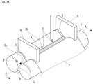
- FIG. 3A is a perspective view of the heating rollers 2 of the first embodiment.
- FIG. 3B is a cross-sectional view along the A-A line of FIG. 3A .
- the reference sign "4'" in FIG. 3B designates cloth 4' to which the matrix resin 5 adheres.
- the adhesion range of the matrix resin 5 can be limited to a range between both the guides 9.
- the pair of heating rollers 2 is provided such that the interval 6 therebetween is adjustable.
- the adhesion amount of the matrix resin 5 adhering to the cloth 4 can be controlled by varying the interval 6 of the pair of heating rollers 2.
- the continuous production device 1 of this embodiment can perform the step of making the matrix resin 5 adhere to the cloth 4, the adjustment of the adhesion amount of the matrix resin 5, and the step of overlaying the release sheet 3 on each surface of the cloth 4 at a time in the gap portion 2b of the heating rollers 2 by the above-described configuration. Therefore, the continuous production device 1 of this embodiment can omit the step of producing the resin film 50, which was required in the conventional hot melt method.
- the prepreg 10 can be produced by continuously performing the adhesion step and the impregnation step of the matrix resin 5, and therefore the productivity and the production workability can be improved.
- the continuous production device 1 accumulates the matrix resin 5 in a space enclosed by the release sheets 3 and the guides 9, and continuously hold the matrix resin 5 as it is between the release sheets 3, and therefore no resin adheres onto the production line, achieving excellent maintainability.
- the continuous production device 1 makes the matrix resin 5 adhere to the cloth 4 by immersing the cloth 4 in the matrix resin 5 accumulated above the gap portion 2b. Therefore, the continuous production device 1 of this embodiment can use, for the production of the prepreg 10, even the matrix resin 5 which has been incapable of producing the resin film 50 due to its low viscosity at room temperature (e.g., 15 to 25°C) or a low temperature (e.g., 0°C or more and less than 15°C) and unsuitable for the conventional hot melt method.
- room temperature e.g., 15 to 25°C
- a low temperature e.g., 0°C or more and less than 15°C
- the continuous production device 1 of this embodiment can reduce the viscosity by heating the matrix resin 5 with the two heating rollers 2. Therefore, the continuous production device 1 of this embodiment is also applicable to a resin having a high viscosity at room temperature or a low temperature.
- the continuous production device 1 is provided with the thickness gauges 7, and therefore can control the adhesion amount (resin content) of the matrix resin 5 by adjusting the interval 6 of the gap portion 2b according to a measured value of the thickness gauges 7.
- the prepreg 10 is always passed through the thickness gauges 7 over the entire length of the prepreg 10, and therefore the resin content over the entire roll of the prepreg 10 can be measured.
- the release sheet 3 is placed on each surface of the cloth 4, and the cloth 4 and the pair of release sheets 3 are passed through the gap portion 2b positioned in a clearance of the pair of heating rollers 2 to be overlaid on each other.
- the matrix resin 5 is supplied between the cloth 4 and the release sheet 3 in the gap portion 2b of the heating rollers 2.
- the cloth 4 is passed through the gap portion 2b in a state of being overlaid and wound on the release sheet 3 wound around the peripheral surface 2c of one heating roller 2, thereby making the matrix resin 5 adhere to one surface of the cloth 4.
- the adhesion amount of the matrix resin 5 is controlled by the interval 6 of the gap portion 2b.
- the thickness gauges 7 are installed and the interval 6 of the pair heating rollers 2 is adjusted based on a measured value of the thickness gauges 7.
- the measured value of the thickness gauges 7 can be fed back to the interval 6 of the gap portion 2b.
- the effects of the prepreg continuous production method of this embodiment are the same as the effects of the continuous production device 1 of this embodiment.
- FIG. 4 is an explanatory view of the continuous production device 1 of a second embodiment.
- the continuous production device 1 of this embodiment has an embodiment of making the matrix resin 5 adhere to the cloth 4 from both surfaces of the cloth 4. Therefore, the continuous production device 1 is different from that of the first embodiment in the angle when the cloth 4 enters the gap portion 2b.
- the continuous production device 1 of this embodiment is provided with a base material roller 14a of fixing a route in which the cloth 4 extends toward the gap portion 2b at an angle at which a clearance is generated between the cloth 4 and each release sheet 3 in the matrix resin 5 accumulated above the gap portion 2b.
- the continuous production device 1 of this embodiment is different from that of the first embodiment.
- the cloth 4 passes up to down through the gap portion 2b between the pair of release sheets 3 without being wound around one heating roller 2.
- the cloth 4 passing through the gap portion 2b preferably vertically extends. This creates a clearance between each release sheet 3 and the cloth 4, and the matrix resin 5 enters the clearance, and therefore the matrix resin 5 can be made to adhere to each surface of the cloth 4 at a time.
- one in which the release sheet 3 is stuck to the matrix resin 5 on each surface of the cloth 4 is extruded from the lower side of the gap portion 2b.
- the continuous production device 1 of this embodiment can make the matrix resin 5 adhere to each surface of the cloth 4 at a time.
- the continuous production device 1 of this embodiment can obtain a good prepreg 10 in which the cloth 4 is sufficiently impregnated with the matrix resin 5 to the inside thereof. This is considered to be because the impregnation with the matrix resin 5 from both surfaces of the cloth 4 halves the distance in the thickness direction of the cloth 4 in which the matrix resin 5 needs to move.
- FIG. 5 is a perspective view of the heating rollers 2 of the second embodiment.
- the resin supply device 8 of this embodiment preferably charges the matrix resin 5 into each of both the front surface side and the rear surface side of the cloth 4 as illustrated in this figure.
- the matrix resin 5 can be made to adhere to the cloth 4 from the front surface side and the rear surface side of the cloth 4, resulting in that the cloth 4 can be impregnated with the matrix resin 5 to the inside thereof with the impregnation rollers 12 positioned on the downstream side.
- the prepreg continuous production method in this embodiment includes passing the cloth 4 through the gap portion 2b such that a clearance is generated between the cloth 4 and each release sheet 3 in the matrix resin 5 accumulated above the gap portion 2b.
- the matrix resin 5 can be made to adhere to each surface of the cloth 4.
- the continuous production device 1 can make resin adhere to the cloth 4 from one surface or both surfaces by changing the route in which the cloth 4 to be passed through the heating rollers 2 extends, depending on the viscosity of the matrix resin 5.
- a non-crimp fabric was used as the cloth 4
- a release film was used as the release sheet 3
- a low viscosity epoxy resin was used as the matrix resin 5.
- a non-crimp fabric with fiber areal weight (FAW) of 900 g/m 2 in which the orientation angles of carbon fibers were +45°/90°/-45° and a stitch yarn was woven, an epoxy resin with a room temperature viscosity of 9 Pa ⁇ s, and an embossed release film containing a polyethylene material were used.
- the heating rollers 2, the hot plates 11, and the impregnation rollers 12 were set to 25°C, and the matrix resin 5 was made to adhere to the cloth 4 on the heating rollers 2 from one surface side as illustrated in FIG. 2 .
- the prepreg 10 As a result of producing the prepreg 10 by controlling the interval 6 of the gap portion 2b between the heating rollers 2 such that the resin content was 36 ⁇ 2 wt% with the thickness gauges 7, the prepreg 10 impregnated with the matrix resin 5 from the supply surface of the matrix resin 5 to the rear surface of the cloth 4 was obtained.
- a non-crimp fabric was used as the cloth 4
- a release film was used as the release sheet 3
- a low viscosity epoxy resin was used as the matrix resin 5.
- a non-crimp fabric with fiber areal weight (FAW) of 450 g/m 2 in which the orientation angles of carbon fibers were +45°/90°/-45° and a stitch yarn was woven, an epoxy resin with a room temperature viscosity of 9 Pa ⁇ s, and an embossed release film containing a polyethylene material were used.
- the heating rollers 2, the hot plates 11, and the impregnation rollers 12 were set to 25°C, and the matrix resin 5 was made to adhere to the cloth 4 on the heating rollers 2 from one surface side as illustrated in FIG. 2 .
- the prepreg 10 As a result of producing the prepreg 10 by controlling the interval 6 of the gap portion 2b between the heating rollers 2 such that the resin content was 36 ⁇ 2 wt% with the thickness gauges 7, the prepreg 10 impregnated with the matrix resin 5 from the supply surface of the matrix resin 5 to the rear surface of the cloth 4 was obtained.
- a non-crimp fabric was used as the cloth 4
- a release paper sheet was used as the release sheet 3
- a high viscosity epoxy resin composition was used as the matrix resin 5.
- FAW fiber areal weight
- the prepreg 10 As a result of producing the prepreg 10 by controlling the interval 6 of the gap portion 2b between the heating rollers 2 such that the resin content was 38 ⁇ 2 wt% with the thickness gauges 7, the prepreg 10 having the impregnation state similar to that in the case of producing the prepreg 10 by the conventional hot melt method was obtained.
- a carbon fiber woven fabric was used as the cloth 4
- a release paper sheet was used as the release sheet 3
- a high viscosity epoxy resin composition was used as the matrix resin 5.
- a carbon fiber plain-woven fabric with fiber areal weight (FAW) of 200 g/m 2 , an epoxy resin composition with a viscosity at room temperature of 100,000 Pa ⁇ s and a viscosity at 80°C of 5 Pa ⁇ s, and a release paper sheet were used.
- FAW fiber plain-woven fabric with fiber areal weight
- the prepreg 10 As a result of producing the prepreg 10 by controlling the interval 6 of the gap portion 2b between the heating rollers 2 such that the resin content was 38 ⁇ 2 wt% with the thickness gauges 7, the prepreg 10 having the impregnation state similar to that in the case of producing the prepreg 10 by the conventional hot melt method was obtained.
- an 8-harness satin woven glass cloth was used as the cloth 4
- a release paper sheet was used as the release sheet 3
- a high viscosity epoxy resin composition was used as the matrix resin 5.
- An 8-harness satin woven glass cloth with fiber areal weight (FAW) of 300 g/m 2 , an epoxy resin composition with a viscosity at room temperature of 100,000 Pa ⁇ s and a viscosity at 80°C of 5 Pa ⁇ s, and a release paper sheet were used.
- FAW 8-harness satin woven glass cloth with fiber areal weight
- the prepreg 10 As a result of producing the prepreg 10 by controlling the interval 6 of the gap portion 2b between the heating rollers 2 such that the resin content was 35 ⁇ 2 wt% with the thickness gauges 7, the prepreg 10 having the impregnation state similar to that in the case of producing the prepreg 10 by the conventional hot melt method was obtained.
- the present invention can perform the step of making the matrix resin 5 adhere to the cloth 4, the adjustment of the adhesion amount of the matrix resin 5, and the step of overlaying the release sheet 3 on each surface of the cloth 4 at a time in the gap portion 2b of the heating rollers 2. Therefore, the present invention can omit the step of producing the resin film 50, which was required in the conventional hot melt method.
- the present invention can produce the prepreg 10 in continuous one step, and therefore can improve the productivity and the production workability.
- the matrix resin 5 is accumulated in the space enclosed by the release sheets 3 and the guides 9 and the matrix resin 5 is continuously held as it is between the release sheets 3, and therefore no resin adheres onto the production line, achieving excellent maintainability.
- the matrix resin 5 is made to adhere to the cloth 4 by immersing the cloth 4 in the matrix resin 5 accumulated above the gap portion 2b.
- the present invention can use, for the production of the prepreg 10, even the matrix resin 5 which has been incapable of producing the resin film 50 due to its low viscosity at room temperature or a low temperature and unsuitable for the conventional hot melt method.
- the viscosity can be reduced by heating the matrix resin 5 with the two heating rollers 2, and therefore the continuous production device 1 of this embodiment is also efficiently applicable to a resin having a high viscosity at room temperature or a low temperature.
- the continuous production device 1 is provided with the thickness gauges 7, and therefore can automatically control the adhesion amount (resin content) of the matrix resin 5 by adjusting the interval 6 of the gap portion 2b according to a measured value of the thickness gauges 7.
- the prepreg 10 always passes through the thickness gauges 7, and therefore the resin content over the entire roll of the prepreg 10 can be measured.
- the cloth 4 is immersed in the matrix resin 5 accumulated above the gap portion 2b, making the matrix resin 5 adhere to the cloth 4. Therefore, the present invention can easily switch between a production line of making the matrix resin 5 adhere to one surface of the cloth 4 and a production line of making the matrix resin 5 adhere to each surface of the cloth 4 by simply changing the route in which the cloth 4 extends when passing the cloth 4 through the heating rollers 2, depending on the viscosity of the matrix resin 5.
Landscapes
- Engineering & Computer Science (AREA)
- Mechanical Engineering (AREA)
- Chemical & Material Sciences (AREA)
- Composite Materials (AREA)
- Reinforced Plastic Materials (AREA)
Description
- The present invention relates to a prepreg continuous production device and a method therefor by a hot melt method.
- The prepreg is a plastic molding material obtained by impregnating a fibrous reinforcement material, such as glass cloth or carbon fibers (hereinafter referred to as "fibrous base material"), with resin, and then heating or drying the resultant fibrous base material into a semi-cured state. For example, in producing an FRP containing fibers and resin, the prepreg is required as an intermediate material thereof. For the fibrous base material of the prepreg, cloth, such as a woven fabric, is used, for example.
- When the viscosity of the resin is high, the resin does not soak into the fibers, and therefore the prepreg production requires a step of reducing the viscosity of the resin. In general, examples of a method for producing the prepreg include a hot melt method and a solvent method.
- The hot melt method includes placing a sheet-like fibrous base material between release paper sheets, to which a matrix resin has been applied, and then heating them in an overlaid state to thereby reduce the viscosity of the matrix resin and impregnate the fibrous base material with the matrix resin.
- On the other hand, the solvent method includes adding a solvent to the matrix resin to reduce the viscosity of the resin, and then impregnating the fibrous base material with the resultant resin, and then evaporating the solvent using a dryer or the like.
- The method for producing the prepreg by the hot melt method is disclosed in
PTL 1, for example. In the method for producing the prepreg ofPTL 1, the matrix resin is applied to each surface of the fibrous base material. -
FIG. 1A is an explanatory view illustrating a first step of a method for producing aprepreg 52 by a conventional hot melt method. - The first step is a step of applying a matrix resin 55 onto a release paper sheet or release
film 53 in the shape of a thin film, and then covering the matrix resin 55 with another release paper sheet or releasefilm 53 to create aresin film 50. Theresin film 50 has a configuration in which two release paper sheets orrelease films 53 hold the matrix resin 55 therebetween and is wound around aroll 56. The film thickness of theresin film 50 is adjusted according to the required amount of the matrix resin 55 in theprepreg 52. -
FIG. 1B is an explanatory view illustrating a second step of the method for producing theprepreg 52 by the conventional hot melt method. - In the method for producing the
prepreg 52 disclosed inPTL 1, afibrous base material 54 is impregnated with the matrix resin 55 from both surfaces thereof as illustrated inFIG. 1B . - The second step of
PTL 1 uses two rolls of theresin film 50 created in the first step. - In the second step, the release paper sheets or release
films 53 on the side facing thefibrous base material 54 of the two rolls of theresin films 50 are first peeled off, and then thefibrous base material 54 is held and stuck between theresin films 50. Thereafter, the resultant substance is heated on ahot plate 61 to reduce the viscosity of the matrix resin 55. By subsequent heating and pressurization withrollers 62, thefibrous base material 54 is impregnated with the matrix resin 55 to complete theprepreg 52. - PTL2 discloses a prepreg production device and a prepreg continuous production method. Specifically, PTL2 discloses to apply a pool of molten resin in a gap portion between a pair of heated rollers and passing a continuous reinforcement fiber through the pool of molten resin to impregnate the fiber with the resin. PTL2 further suggests to adjust the gap between the rollers to control the amount of resin applied to the fiber.
- PTL 1: International Publication
WO 2010/150022 PTL 2:US2012/251823 A1 - As described above, the method for producing the
prepreg 52 by the conventional hot melt method has required the two steps of the first step of producing theresin film 50 and the second step of impregnating thefibrous base material 54 with the matrix resin 55 of theresin film 50, and thus the productivity has not been good. - When a low viscosity resin is used for the conventional hot melt method, the resin cannot be left on only one release paper sheet or release
film 53 in peeling off the resin from the release paper sheet or releasefilms 53 in the second step, so that the film thickness is not fixed. Therefore, the conventional hot melt method has not been applicable to the impregnation of thefibrous base material 54 with the low viscosity resin. - The present invention has been conceived in order to solve the above-described problems. More specifically, it is an object of the present invention to provide a prepreg continuous production device and a method therefor by a hot melt method not requiring a step of creating a resin film and usable even for a low viscosity resin.
- The present invention provides a prepreg continuous production device according to the subject-matter of the
independent claim 1. - The present invention also provides a prepreg continuous production method according to the subject-matter of the
independent claim 6. - According to the present invention described above, the pair of release sheets and the cloth arranged therebetween pass through the gap portion of the pair of heating rollers and the matrix resin is supplied to be accumulated above the gap portion and between the pair of release sheets. Thus, the present invention can perform the step of making the matrix resin adhere to the cloth, the adjustment of the adhesion amount of the matrix resin, and the step of overlaying the release sheet on each surface of the cloth at a time in the gap portion of the heating rollers. Therefore, the present invention can omit a step of producing a resin film, which was required in the conventional hot melt method.
- Further, the present invention can produce a prepreg in continuous one step, and therefore can improve the productivity and the production workability.
- Further, the present invention makes the matrix resin adhere to the cloth by immersing the cloth in the matrix resin accumulated above the gap portion. Therefore, the present invention can use, for the production of the prepreg, even the matrix resin which has been incapable of producing a resin film due to its low viscosity at room temperature or a low temperature and unsuitable for the conventional hot melt method.
-
-
FIG. 1A is an explanatory view illustrating a first step of a method for producing a prepreg by a conventional hot melt method. -
FIG. 1B is an explanatory view illustrating a second step of the method for producing a prepreg by the conventional hot melt method. -
FIG. 2 is an explanatory view of a prepreg continuous production device of a first embodiment. -
FIG. 3A is a perspective view of heating rollers of the first embodiment. -
FIG. 3B is a cross-sectional view along the A-A line ofFIG. 3A . -
FIG. 4 is an explanatory view of a prepreg continuous production device of a second embodiment. -
FIG. 5 is a perspective view of heating rollers of the second embodiment. - Hereinafter, embodiments of the present invention are described based on the drawings. The same signs are attached to common parts in the drawings and duplicate descriptions are omitted.
-
FIG. 2 is an explanatory view of a prepregcontinuous production device 1 of a first embodiment. This embodiment is an embodiment of making amatrix resin 5 adhere to one surface ofcloth 4. - The prepreg continuous production device 1 (hereinafter referred to as "
continuous production device 1") is a device of producing aprepreg 10 in continuous one step of a hot melt method using amatrix resin 5. Thecontinuous production device 1 includes a pair ofheating rollers 2, a pair ofrelease sheet reels 13, acloth reel 14, and aresin supply device 8. - When using the
continuous production device 1, tworelease sheets 3, thecloth 4, and thematrix resin 5 are charged into agap portion 2b positioned in a clearance between the pair ofheating rollers 2. Thus, thecontinuous production device 1 can produce one in which thematrix resin 5 adheres to thecloth 4 and each surface thereof is covered with therelease sheet 3 at a time. - The
matrix resin 5 is a thermosetting resin or a thermoplastic resin or a mixture thereof and has a characteristic that the viscosity decreases when heated once. Thematrix resin 5 of this embodiment is preferably a solvent-free resin, but may be a matrix resin containing a solvent, depending on the requirements of theprepreg 10. Thematrix resin 5 is first charged into thegap portion 2b between the pair ofheating rollers 2. - The pair of
heating rollers 2 are adjacent to each other and form one set and rotate around axes ofrotation 2a extending horizontally and parallel to each other. A pair ofrelease sheets 3 and thecloth 4 are placed overperipheral surfaces 2c of theheating rollers 2 from above to below through thegap portion 2b. Theresin supply device 8 charges thematrix resin 5 between therelease sheets 3 and thecloth 4. - At this time, the
resin supply device 8 supplies thematrix resin 5 to be accumulated above thegap portion 2b and between the pair ofrelease sheets 3. For example, theresin supply device 8 may be aresin tank 8a and apump 8b as illustrated in this figure. In this case, thematrix resin 5 is transferred from theresin tank 8a by thepump 8b or the like to be charged into thegap portion 2b. - When each of the
heating rollers 2 rotates such that theperipheral surface 2c of theheating roller 2 in thegap portion 2b moves from above to below, therelease sheets 3, thecloth 4, and thematrix resin 5 pass through thegap portion 2b from above to below and are extruded from the lower side while being overlaid on each other. At this time, the viscosity of thematrix resin 5 above thegap portion 2b is preferably 0.5 Pa·s or more and 100 Pa·s or less. This is because, when the viscosity of thematrix resin 5 above thegap portion 2b is less than 0.5 Pa·s, thematrix resin 5 tends to flow downward in the vertical direction from thegap portion 2b through thecloth 4, making it difficult to control the progress speed of the production line and adjust the adhesion amount of thematrix resin 5. - For example, it is preferable that the
heating rollers 2 in the case of using thematrix resin 5 having a high viscosity at room temperature or a low temperature can heat thematrix resin 5 until the viscosity of thematrix resin 5 reaches 0.5 Pa·s or more and 100 Pa·s or less. - At this time, the viscosity of the
matrix resin 5 above thegap portion 2b is particularly preferably 0.5 Pa·s or more and 10 Pa·s or less. The viscosity of thematrix resin 5 above thegap portion 2b is particularly preferably 10 Pa·s or less, because, when the viscosity is larger than 10 Pa·s, it takes time to feed thematrix resin 5 downward by theheating rollers 2, decreasing the productivity of theprepreg 10. - The
heating rollers 2 are also preferably configured to be able to control the distance of a clearance of thegap portion 2b. For example, theheating rollers 2 may have an actuator 15 moving oneheating roller 2 horizontally toward theother heating roller 2 together with amotor 2d rotating the axis ofrotation 2a of oneheating roller 2. It is preferable that acontrol device 16 is connected to theactuator 15 and thecontrol device 16 drives theactuator 15 to adjust the distance of the clearance of thegap portion 2b. Theactuator 15 is not limited to the configuration illustrated in this figure and may also be provided in theheating roller 2 around which thecloth 4 is wound or may be provided in both theheating rollers 2. Theheating roller 2 around which thecloth 4 is wound may be either the right orleft heating roller 2 in this figure. - The
release sheet reels 13 are devices capable of rewinding therelease sheets 3 toward theperipheral surfaces 2c of the pair ofheating rollers 2. Onerelease sheet reel 13 is provided for oneheating roller 2, forming one pair in total. It is preferable that therelease sheet reels 13 have a braking mechanism of stopping the rotation of therelease sheets 3 in addition to the rewinding of therelease sheets 3 by generating back tension in therelease sheets 3. - The
release sheets 3 are film-like artifacts which are used to hold thecloth 4 and thematrix resin 5 from both surfaces. In thecontinuous production device 1, a pair of release sheets 3 (2 rolls) is used. As illustrated in this figure, onerelease sheet 3 is arranged for oneheating roller 2 and passes up to down through thegap portion 2b of theheating roller 2. - The
release sheets 3 may be, for example, release films or release paper sheets. It is preferable to properly use the release film or the release paper sheet depending on the temperature of theheating rollers 2 orhot plates 11 in producing theprepreg 10 or the releasability from a material. - The
cloth reel 14 is a device capable of rewinding thecloth 4 in between the pair ofrelease sheets 3. It is preferable that thecloth reel 14 also has a braking mechanism of stopping the rotation of thecloth 4 in addition to the rewinding of thecloth 4 by generating back tension in thecloth 4. - The
cloth 4 of this embodiment may be a fibrous base material obtained by entangling fibers containing inorganic materials, such as carbon fibers or glass fibers, or organic fibers, such as aramid fibers, nylon fibers, or polyester fibers, with each other to form a sheet. Thecloth 4 may be various woven fabrics, Non-Crimp Fabrics (NCF), knitted fabrics, or non-woven fabrics, such as compressed wool or felt cloth, and does not include those in which fibers are oriented and aligned in one direction. Thecontinuous production device 1 of this embodiment is installed such that thecloth 4 is wound around a part of theperipheral surface 2c of oneheating roller 2 with onerelease sheet 3 interposed therebetween. Thus, thecontinuous production device 1 can make thematrix resin 5 adhere only to one surface of thecloth 4. - With this configuration, the
cloth 4 having one surface to which thematrix resin 5 adheres and held between the pair ofrelease sheets 3 from the outside is extruded from the lower side of thegap portion 2b of theheating rollers 2. At this time, a sheet extruded from thegap portion 2b is in a state where the pair ofrelease sheets 3 and thecloth 4 having one surface to which thematrix resin 5 adheres are overlaid on each other. - As described above, the
continuous production device 1 accumulates thematrix resin 5 above thegap portion 2b covered with the pair ofrelease sheets 3. By passing thecloth 4 up to down through thegap portion 2b while immersing thecloth 4 in the accumulatedmatrix resin 5, thematrix resin 5 is made to adhere to thecloth 4. - Due to the configuration of the
continuous production device 1 in which thematrix resin 5 is accumulated in thegap portion 2b between the twoheating rollers 2 and passing thecloth 4 through thematrix resin 5, the rotation of theheating rollers 2 can forcibly and positively promote the impregnation of thecloth 4 with thematrix resin 5, as compared with a case of simply passing thecloth 4 through thematrix resin 5 accumulated in a container. - Further, this configuration can supply the
release sheets 3 to thegap portion 2b by rotating theheating rollers 2, (1) following the progress speed of the production line, (2) along the twoheating rollers 2, and (3) under tension. As a result, thegap portion 2b does not need to be cleaned, and therefore the maintainability is more excellent than that in the case of simply passing thecloth 4 through thematrix resin 5 accumulated in a container. - In addition thereto, when the
cloth 4 is simply passed through thematrix resin 5 accumulated in a container, the adhesion amount of thematrix resin 5 cannot be adjusted, whereas thecontinuous production device 1 of this embodiment can easily adjust the adhesion amount of thematrix resin 5 because the adhesion amount of thematrix resin 5 is adjusted by the width of the roller gap of the heating rollers 2 (interval 6 of thegap portion 2b (seeFIG. 3A )). - On the downstream side of the pair of
heating rollers 2, thickness gauges 7 are preferably provided. The thickness gauges 7 are preferably, for example, X-ray thickness gauges or β-ray thickness gauges. - For example, it may be acceptable that the thickness gauges 7 are arranged immediately behind the
heating rollers 2 and hold the sheet extruded from thegap portion 2b therebetween between the top and bottom, and one thickness gauge 7 emits X-rays or β-rays and the other thickness gauge 7 receives the X-rays or the β-rays. In that case, the thickness gauge 7 may be one measuring the mass per unit area from the attenuation of the X-rays or the β-rays transmitting through a measurement target, and multiplying the mass by the density, thereby calculating the thickness of the measurement target, for example. Thus, the thickness gauges 7 measure the mass per unit area in a state where the tworelease sheets 3, thecloth 4, and thematrix resin 5 are overlaid on each other. - When the thickness gauges 7 transmit information on the acquired thickness of the measurement target to the
control device 16, thecontrol device 16 acquires the adhesion amount of thematrix resin 5 by treating the mass obtained from the attenuation of the X-rays or the β-rays in the tworelease sheets 3 and thecloth 4 as a constant. Thecontrol device 16 feeds back the calculated adhesion amount of thematrix resin 5 to theinterval 6 of thegap portion 2b of theheating rollers 2, so thatcontinuous production device 1 controls the adhesion amount of thematrix resin 5. - The adjustment of the
interval 6 of the pair ofheating rollers 2 based on a measured value of the thickness gauges 7 may be manually performed. - As described above, the
continuous production device 1 can adjust theinterval 6 of the pair ofheating rollers 2 based on the measured value of the thickness gauges 7 manually, or automatically with thecontrol device 16. - In order to sufficiently impregnate the
cloth 4 with thematrix resin 5, thecontinuous production device 1 is preferably provided with thehot plates 11,impregnation rollers 12, coolingplates 19,drive rollers 17, and a windingdevice 18 on the downstream side of theheating rollers 2. - The
hot plates 11 are plates for heating to reduce the viscosity of thematrix resin 5 adhering to thecloth 4 once. During the passage of thecloth 4 held between therelease sheets 3 between thehot plates 11 provided up and down, thematrix resin 5 is heated, so that the viscosity is reduced. This is the preparation for the impregnation of thecloth 4 with thematrix resin 5 by theimpregnation rollers 12. - The
impregnation rollers 12 contain a pair of pressurization rollers capable of performing either or both of pressurization and heating of thecloth 4 to which thematrix resin 5 adheres. Thus, thecloth 4 can be impregnated with thematrix resin 5 adhering to the surface of thecloth 4 to the inside thereof, forming auniform prepreg 10. - The
prepreg 10 is an intermediate material to be used in producing plastic products, such as FRP, and therefore, in the case of a thermosetting resin, thematrix resin 5 of theprepreg 10 is preferably in a semi-cured state in terms of workability in lamination. The coolingplates 19 contain a pair of cooling plates arranged up and down and are used to cool theheated prepreg 10 by passing it between the upper andlower cooling plates 19. Thus, theheated matrix resin 5 can be cooled, so that the progress of a curing reaction can be suppressed. - The
drive rollers 17 contain a pair of rollers and hold theprepreg 10 therebetween and move it at a constant speed. - The winding
device 18 is a device of winding the completedprepreg 10 onto a paper tube. The windingdevice 18 is preferably provided with a function of aligning end portions with an EPC sensor or the like. -
FIG. 3A is a perspective view of theheating rollers 2 of the first embodiment.FIG. 3B is a cross-sectional view along the A-A line ofFIG. 3A . The reference sign "4'" inFIG. 3B designates cloth 4' to which thematrix resin 5 adheres. - As illustrated in this figure, guides 9 provided following the shape of the
heating rollers 2 are provided in thegap portion 2b at both end portions of the adhesion range of thematrix resin 5 in the axial direction of theheating rollers 2. Thus, the adhesion range of thematrix resin 5 can be limited to a range between both theguides 9. - At this time, when L1 is set as the distance between the insides of the pair of
guides 9, L2 is set as the distance between the outsides of theguides 9, W1 is set as the widths of thecloths 4, 4', and W2 is set as the width of therelease sheet 3, the followingequations Equation 1, thecloth 4 can be surely prevented from being folded by theguides 9 and held between therelease sheets 3, and therefore thematrix resin 5 can be uniformly made to adhere to thecloth 4 in the width direction. Further, by satisfyingEquation 2, thematrix resin 5 is surely held between therelease sheets 3, and therefore the adhesion of thematrix resin 5 to theheating rollers 2 can be prevented.

- As described in
FIG. 2 , the pair ofheating rollers 2 is provided such that theinterval 6 therebetween is adjustable. Thus, the adhesion amount of thematrix resin 5 adhering to thecloth 4 can be controlled by varying theinterval 6 of the pair ofheating rollers 2. - The
continuous production device 1 of this embodiment can perform the step of making thematrix resin 5 adhere to thecloth 4, the adjustment of the adhesion amount of thematrix resin 5, and the step of overlaying therelease sheet 3 on each surface of thecloth 4 at a time in thegap portion 2b of theheating rollers 2 by the above-described configuration. Therefore, thecontinuous production device 1 of this embodiment can omit the step of producing theresin film 50, which was required in the conventional hot melt method. - Further, the
prepreg 10 can be produced by continuously performing the adhesion step and the impregnation step of thematrix resin 5, and therefore the productivity and the production workability can be improved. - Further, the
continuous production device 1 accumulates thematrix resin 5 in a space enclosed by therelease sheets 3 and theguides 9, and continuously hold thematrix resin 5 as it is between therelease sheets 3, and therefore no resin adheres onto the production line, achieving excellent maintainability. - Further, the
continuous production device 1 makes thematrix resin 5 adhere to thecloth 4 by immersing thecloth 4 in thematrix resin 5 accumulated above thegap portion 2b. Therefore, thecontinuous production device 1 of this embodiment can use, for the production of theprepreg 10, even thematrix resin 5 which has been incapable of producing theresin film 50 due to its low viscosity at room temperature (e.g., 15 to 25°C) or a low temperature (e.g., 0°C or more and less than 15°C) and unsuitable for the conventional hot melt method. - Further, in the case of the
matrix resin 5 having a high viscosity at room temperature or a low temperature, thecontinuous production device 1 of this embodiment can reduce the viscosity by heating thematrix resin 5 with the twoheating rollers 2. Therefore, thecontinuous production device 1 of this embodiment is also applicable to a resin having a high viscosity at room temperature or a low temperature. - Further, the
continuous production device 1 is provided with the thickness gauges 7, and therefore can control the adhesion amount (resin content) of thematrix resin 5 by adjusting theinterval 6 of thegap portion 2b according to a measured value of the thickness gauges 7. - Further, the
prepreg 10 is always passed through the thickness gauges 7 over the entire length of theprepreg 10, and therefore the resin content over the entire roll of theprepreg 10 can be measured. - Next, a prepreg continuous production method in this embodiment is described.
- As illustrated in
FIG. 2 , therelease sheet 3 is placed on each surface of thecloth 4, and thecloth 4 and the pair ofrelease sheets 3 are passed through thegap portion 2b positioned in a clearance of the pair ofheating rollers 2 to be overlaid on each other. In addition thereto, thematrix resin 5 is supplied between thecloth 4 and therelease sheet 3 in thegap portion 2b of theheating rollers 2. - In this embodiment, the
cloth 4 is passed through thegap portion 2b in a state of being overlaid and wound on therelease sheet 3 wound around theperipheral surface 2c of oneheating roller 2, thereby making thematrix resin 5 adhere to one surface of thecloth 4. The adhesion amount of thematrix resin 5 is controlled by theinterval 6 of thegap portion 2b. - On the downstream side of the
pair heating rollers 2, the thickness gauges 7 are installed and theinterval 6 of thepair heating rollers 2 is adjusted based on a measured value of the thickness gauges 7. - Thus, the measured value of the thickness gauges 7 can be fed back to the
interval 6 of thegap portion 2b. - The effects of the prepreg continuous production method of this embodiment are the same as the effects of the
continuous production device 1 of this embodiment. -
FIG. 4 is an explanatory view of thecontinuous production device 1 of a second embodiment. Thecontinuous production device 1 of this embodiment has an embodiment of making thematrix resin 5 adhere to thecloth 4 from both surfaces of thecloth 4. Therefore, thecontinuous production device 1 is different from that of the first embodiment in the angle when thecloth 4 enters thegap portion 2b. - Specifically, the
continuous production device 1 of this embodiment is provided with abase material roller 14a of fixing a route in which thecloth 4 extends toward thegap portion 2b at an angle at which a clearance is generated between thecloth 4 and eachrelease sheet 3 in thematrix resin 5 accumulated above thegap portion 2b. In this point, thecontinuous production device 1 of this embodiment is different from that of the first embodiment. Thus, thecloth 4 passes up to down through thegap portion 2b between the pair ofrelease sheets 3 without being wound around oneheating roller 2. Thecloth 4 passing through thegap portion 2b preferably vertically extends. This creates a clearance between eachrelease sheet 3 and thecloth 4, and thematrix resin 5 enters the clearance, and therefore thematrix resin 5 can be made to adhere to each surface of thecloth 4 at a time. Then, one in which therelease sheet 3 is stuck to thematrix resin 5 on each surface of thecloth 4 is extruded from the lower side of thegap portion 2b. - Thus, the
continuous production device 1 of this embodiment can make thematrix resin 5 adhere to each surface of thecloth 4 at a time. - In the case of the
matrix resin 5 of a high viscosity type, it is sometimes difficult to impregnate thecloth 4 with thematrix resin 5 to the rear surface side thereof even when thematrix resin 5 is supplied only to one surface. Even when thematrix resin 5 of such a high viscosity type is used, thecontinuous production device 1 of this embodiment can obtain agood prepreg 10 in which thecloth 4 is sufficiently impregnated with thematrix resin 5 to the inside thereof. This is considered to be because the impregnation with thematrix resin 5 from both surfaces of thecloth 4 halves the distance in the thickness direction of thecloth 4 in which thematrix resin 5 needs to move. -
FIG. 5 is a perspective view of theheating rollers 2 of the second embodiment. When thematrix resin 5 is charged between each of the pair ofrelease sheets 3 and thecloth 4, theresin supply device 8 of this embodiment preferably charges thematrix resin 5 into each of both the front surface side and the rear surface side of thecloth 4 as illustrated in this figure. Thus, even when the viscosity of thematrix resin 5 is high, thematrix resin 5 can be made to adhere to thecloth 4 from the front surface side and the rear surface side of thecloth 4, resulting in that thecloth 4 can be impregnated with thematrix resin 5 to the inside thereof with theimpregnation rollers 12 positioned on the downstream side. - The other configurations and effects of the
continuous production device 1 of this embodiment are the same as those in the first embodiment. - Further, the prepreg continuous production method in this embodiment includes passing the
cloth 4 through thegap portion 2b such that a clearance is generated between thecloth 4 and eachrelease sheet 3 in thematrix resin 5 accumulated above thegap portion 2b. Thus, thematrix resin 5 can be made to adhere to each surface of thecloth 4. - The other effects of the prepreg continuous production method of this embodiment are the same as those in the first embodiment.
- Thus, the
continuous production device 1 can make resin adhere to thecloth 4 from one surface or both surfaces by changing the route in which thecloth 4 to be passed through theheating rollers 2 extends, depending on the viscosity of thematrix resin 5. - Next, examples of the prepreg
continuous production device 1 are described. - In the
continuous production device 1 of this example, a non-crimp fabric was used as thecloth 4, a release film was used as therelease sheet 3, and a low viscosity epoxy resin was used as thematrix resin 5. - A non-crimp fabric with fiber areal weight (FAW) of 900 g/m2 in which the orientation angles of carbon fibers were +45°/90°/-45° and a stitch yarn was woven, an epoxy resin with a room temperature viscosity of 9 Pa·s, and an embossed release film containing a polyethylene material were used. The
heating rollers 2, thehot plates 11, and theimpregnation rollers 12 were set to 25°C, and thematrix resin 5 was made to adhere to thecloth 4 on theheating rollers 2 from one surface side as illustrated inFIG. 2 . - As a result of producing the
prepreg 10 by controlling theinterval 6 of thegap portion 2b between theheating rollers 2 such that the resin content was 36 ± 2 wt% with the thickness gauges 7, theprepreg 10 impregnated with thematrix resin 5 from the supply surface of thematrix resin 5 to the rear surface of thecloth 4 was obtained. - In the
continuous production device 1 of this example, a non-crimp fabric was used as thecloth 4, a release film was used as therelease sheet 3, and a low viscosity epoxy resin was used as thematrix resin 5. - A non-crimp fabric with fiber areal weight (FAW) of 450 g/m2 in which the orientation angles of carbon fibers were +45°/90°/-45° and a stitch yarn was woven, an epoxy resin with a room temperature viscosity of 9 Pa·s, and an embossed release film containing a polyethylene material were used. The
heating rollers 2, thehot plates 11, and theimpregnation rollers 12 were set to 25°C, and thematrix resin 5 was made to adhere to thecloth 4 on theheating rollers 2 from one surface side as illustrated inFIG. 2 . - As a result of producing the
prepreg 10 by controlling theinterval 6 of thegap portion 2b between theheating rollers 2 such that the resin content was 36 ± 2 wt% with the thickness gauges 7, theprepreg 10 impregnated with thematrix resin 5 from the supply surface of thematrix resin 5 to the rear surface of thecloth 4 was obtained. - In the
continuous production device 1 of this example, a non-crimp fabric was used as thecloth 4, a release paper sheet was used as therelease sheet 3, and a high viscosity epoxy resin composition was used as thematrix resin 5. - A non-crimp fabric with fiber areal weight (FAW) of 530 g/m2 in which the orientation angles of carbon fibers were +45°/-45° and a stitch yarn was woven, an epoxy resin composition with a viscosity at room temperature of 100,000 Pa·s and a viscosity at 80°C of 5 Pa·s, and a release paper sheet were used. By setting the
heating rollers 2, thehot plates 11, and theimpregnation rollers 12 to 80°C, the viscosity of thematrix resin 5 was reduced, and thematrix resin 5 was made to adhere to thecloth 4 on theheating rollers 2 from both surface sides as illustrated inFIG. 4 . - As a result of producing the
prepreg 10 by controlling theinterval 6 of thegap portion 2b between theheating rollers 2 such that the resin content was 38 ± 2 wt% with the thickness gauges 7, theprepreg 10 having the impregnation state similar to that in the case of producing theprepreg 10 by the conventional hot melt method was obtained. - In the
continuous production device 1 in this example, a carbon fiber woven fabric was used as thecloth 4, a release paper sheet was used as therelease sheet 3, and a high viscosity epoxy resin composition was used as thematrix resin 5. - A carbon fiber plain-woven fabric with fiber areal weight (FAW) of 200 g/m2, an epoxy resin composition with a viscosity at room temperature of 100,000 Pa·s and a viscosity at 80°C of 5 Pa·s, and a release paper sheet were used. By setting the
heating rollers 2, thehot plates 11, and theimpregnation rollers 12 to 80°C, the viscosity of thematrix resin 5 was reduced, and thematrix resin 5 was made to adhere to thecloth 4 on theheating rollers 2 from both surface sides as illustrated inFIG. 4 . - As a result of producing the
prepreg 10 by controlling theinterval 6 of thegap portion 2b between theheating rollers 2 such that the resin content was 38 ± 2 wt% with the thickness gauges 7, theprepreg 10 having the impregnation state similar to that in the case of producing theprepreg 10 by the conventional hot melt method was obtained. - In the
continuous production device 1 in this example, an 8-harness satin woven glass cloth was used as thecloth 4, a release paper sheet was used as therelease sheet 3, and a high viscosity epoxy resin composition was used as thematrix resin 5. - An 8-harness satin woven glass cloth with fiber areal weight (FAW) of 300 g/m2, an epoxy resin composition with a viscosity at room temperature of 100,000 Pa·s and a viscosity at 80°C of 5 Pa·s, and a release paper sheet were used. By setting the
heating rollers 2, thehot plates 11, and theimpregnation rollers 12 to 80°C, the viscosity of thematrix resin 5 was reduced, and thematrix resin 5 was made to adhere to thecloth 4 on theheating rollers 2 from both surface sides as illustrated inFIG. 4 . - As a result of producing the
prepreg 10 by controlling theinterval 6 of thegap portion 2b between theheating rollers 2 such that the resin content was 35 ± 2 wt% with the thickness gauges 7, theprepreg 10 having the impregnation state similar to that in the case of producing theprepreg 10 by the conventional hot melt method was obtained. - According to the above-described present invention, the pair of
release sheets 3 and thecloth 4 placed therebetween pass through thegap portion 2b of the pair ofheating rollers 2 and thematrix resin 5 is supplied to be accumulated above thegap portion 2b and between the pair ofrelease sheets 3. Thus, the present invention can perform the step of making thematrix resin 5 adhere to thecloth 4, the adjustment of the adhesion amount of thematrix resin 5, and the step of overlaying therelease sheet 3 on each surface of thecloth 4 at a time in thegap portion 2b of theheating rollers 2. Therefore, the present invention can omit the step of producing theresin film 50, which was required in the conventional hot melt method. - Further, the present invention can produce the
prepreg 10 in continuous one step, and therefore can improve the productivity and the production workability. - Further, according to the present invention, the
matrix resin 5 is accumulated in the space enclosed by therelease sheets 3 and theguides 9 and thematrix resin 5 is continuously held as it is between therelease sheets 3, and therefore no resin adheres onto the production line, achieving excellent maintainability. - Further, according to the present invention, the
matrix resin 5 is made to adhere to thecloth 4 by immersing thecloth 4 in thematrix resin 5 accumulated above thegap portion 2b. Thus, the present invention can use, for the production of theprepreg 10, even thematrix resin 5 which has been incapable of producing theresin film 50 due to its low viscosity at room temperature or a low temperature and unsuitable for the conventional hot melt method. - For the
matrix resin 5 having a high viscosity at room temperature or a low temperature, the viscosity can be reduced by heating thematrix resin 5 with the twoheating rollers 2, and therefore thecontinuous production device 1 of this embodiment is also efficiently applicable to a resin having a high viscosity at room temperature or a low temperature. - Further, the
continuous production device 1 is provided with the thickness gauges 7, and therefore can automatically control the adhesion amount (resin content) of thematrix resin 5 by adjusting theinterval 6 of thegap portion 2b according to a measured value of the thickness gauges 7. - Further, the
prepreg 10 always passes through the thickness gauges 7, and therefore the resin content over the entire roll of theprepreg 10 can be measured. - Further, according to the present invention, the
cloth 4 is immersed in thematrix resin 5 accumulated above thegap portion 2b, making thematrix resin 5 adhere to thecloth 4. Therefore, the present invention can easily switch between a production line of making thematrix resin 5 adhere to one surface of thecloth 4 and a production line of making thematrix resin 5 adhere to each surface of thecloth 4 by simply changing the route in which thecloth 4 extends when passing thecloth 4 through theheating rollers 2, depending on the viscosity of thematrix resin 5. -
- 1
- prepreg continuous production device (continuous production device)
- 2
- heating roller
- 2a
- axis of rotation
- 2b
- gap portion
- 2c
- peripheral surface
- 2d
- motor
- 3
- release sheet
- 4, 4'
- cloth
- 5
- matrix resin
- 6
- interval
- 7
- thickness gauge
- 8
- resin supply device
- 8a
- resin tank
- 8b
- pump
- 9
- guide
- 10
- prepreg
- 11
- hot plate
- 12
- impregnation roller
- 13
- release sheet reel
- 14
- cloth reel
- 14a
- base material roller
- 15
- actuator
- 16
- control device
- 17
- drive roller
- 18
- winding device
- 19
- cooling plate
- 50
- resin film
- 52
- prepreg
- 53
- release paper sheet or release film
- 54
- fibrous base material
- 55
- matrix resin
- 56
- roll
- 61
- hot plate
- 62
- roller
Claims (10)
- A prepreg continuous production device (1) comprising:a pair of heating rollers (2) adjacent to each other and rotating around axes of rotation (2a) extending horizontally and parallel to each other;a pair of release sheet reels (13) capable of unwinding release sheets (3) toward peripheral surfaces (2c) of the pair of heating rollers (2);a cloth reel (13) capable of unwinding cloth (4) in between the pair of release sheets (3);and a resin supply device (8) supplying a matrix resin (5) to be accumulated above a gap portion (2b) positioned in a clearance of the pair of heating rollers (2) and between the pair of release sheets (3), in whichthe heating rollers (2) each rotate such that the peripheral surfaces (2c) of the heating rollers (2) in the gap portion (2b) move from above to below and extrude, in a downward direction, the release sheets (3), the cloth (4), and the matrix resin (5) passing through the gap portion (2b) from above to below in an overlaid state, andan adhesion amount of the matrix resin (5) adhering to the cloth (4) is controlled by varying an interval (6) of the pair of heating rollers (2),characterized in thata pair of guides (9) following the shape of the heating rollers are provided in the gap portion (2b) at both end portions of the adhesion range of the matrix resin (5) in the axial direction of the heating rollers (2); andthe pair of guides (9) limits the adhesion range of the matrix resin (5) to a range between both the guides (9).
- The prepreg continuous production device (1) according to claim 1 comprising:a thickness gauge (7) on a downstream side of the pair of heating rollers (2), whereinthe interval (6) of the pair of heating rollers (2) is adjusted based on a measured value of the thickness gauge (7).
- The prepreg continuous production device (1) according to claim 1 or 2, wherein
the heating rollers (2) can heat the matrix resin (5) until a viscosity of the matrix resin (5) reaches 0.5 Pa·s or more and 100 Pa·s or less. - The prepreg continuous production device (1) according to any one of claims 1 to 3, comprising:
a base material roller (14a) fixing a route in which the cloth (4) extends toward the gap portion (2b) at an angle at which a clearance is generated between the cloth (4) and each of the release sheets (3) in the matrix resin (5) accumulated above the gap portion (2b). - The prepreg continuous production device (1) according to any one of claims 1 to 4, comprising:a pair of impregnation rollers (12) positioned on the downstream side of the pair of heating rollers (2) and performing either or both of pressurization and heating of the cloth (4) to which the matrix resin (5) adheres and impregnating the cloth (4) with the matrix resin (5) from a surface to an inside of the cloth (4);a pair of drive rollers (17) holding a prepreg (10) in which the cloth (4) is impregnated with the matrix resin (5) to an inside of the cloth (4) and moving the prepreg (10) at a constant speed; anda winding device (18) winding the completed prepreg (10).
- A prepreg continuous production method, the prepreg in which a matrix resin (5) adheres to cloth (4), comprising:arranging a release sheet (3) on each surface of the cloth (4) ;passing the cloth (4) and a pair of the release sheets (3) through a gap portion (2b) positioned in a clearance of a pair of heating rollers (2) to be overlaid on each other and supplying the matrix resin (5) to be accumulated above the gap portion (2b) of the heating rollers (2) and between the pair of release sheets (3); andadjusting an interval (6) of the pair of heating rollers (2) to thereby control an adhesion amount of the matrix resin (5) ;characterized in that the method further comprises providing a pair of guides (9) following the shape of the heating rollers in the gap portion (2b) at both end portions of the adhesion range of the matrix resin (5) in the axial direction of the heating rollers (2) to limit the adhesion range of the matrix resin (5) to a range between both the guides (9).
- The prepreg continuous production method according to claim 6 comprising:installing a thickness gauge (7) on a downstream side of the pair of heating rollers (2), andadjusting the interval (6) of the pair of heating rollers (2) based on a measured value of the thickness gauge (7).
- The prepreg continuous production method according to claim 6 or 7 comprising:
passing the cloth (4) through the gap portion (2b) such that a clearance is generated between the cloth (4) and each of the release sheets (3) in the matrix resin (5) accumulated above the gap portion (2b), and making the matrix resin (5) adhere to each surface of the cloth (4). - The prepreg continuous production method according to claim 6 or 7 comprising:
passing the cloth (4) through the gap portion (2b) in a state of being overlaid and wound on the release sheet (3) wound around a peripheral surface of one of the heating rollers (2), and making the matrix resin (5) adhere to one surface of the cloth (4). - The prepreg continuous production method according to any one of claims 6 to 9, wherein
a viscosity of the matrix resin (5) above the gap portion (2b) is 0.5 Pa·s or more and 100 Pa·s or less.
Applications Claiming Priority (2)
| Application Number | Priority Date | Filing Date | Title |
|---|---|---|---|
| JP2019089596A JP6883827B2 (en) | 2019-05-10 | 2019-05-10 | Prepreg continuous manufacturing equipment and its method |
| PCT/JP2020/014180 WO2020230464A1 (en) | 2019-05-10 | 2020-03-27 | Prepreg continuous production device and method therefor |
Publications (3)
| Publication Number | Publication Date |
|---|---|
| EP3967470A1 EP3967470A1 (en) | 2022-03-16 |
| EP3967470A4 EP3967470A4 (en) | 2022-06-29 |
| EP3967470B1 true EP3967470B1 (en) | 2024-02-28 |
Family
ID=73221345
Family Applications (1)
| Application Number | Title | Priority Date | Filing Date |
|---|---|---|---|
| EP20805329.8A Active EP3967470B1 (en) | 2019-05-10 | 2020-03-27 | Prepreg continuous production device and method therefor |
Country Status (4)
| Country | Link |
|---|---|
| US (1) | US12427732B2 (en) |
| EP (1) | EP3967470B1 (en) |
| JP (1) | JP6883827B2 (en) |
| WO (1) | WO2020230464A1 (en) |
Families Citing this family (3)
| Publication number | Priority date | Publication date | Assignee | Title |
|---|---|---|---|---|
| KR102177348B1 (en) * | 2019-07-18 | 2020-11-11 | 순천향대학교 산학협력단 | Manufacture method for long fiber composite |
| DE102021123510A1 (en) * | 2021-09-10 | 2023-03-16 | Schmidt & Heinzmann Gmbh & Co Kg | Production device, in particular SMC production device, for the production of duroplastic semi-finished products |
| KR102562403B1 (en) * | 2022-09-26 | 2023-08-01 | 차병근 | Blackout fabric manufacturing equipment for roll screen |
Family Cites Families (14)
| Publication number | Priority date | Publication date | Assignee | Title |
|---|---|---|---|---|
| US3616068A (en) * | 1968-09-09 | 1971-10-26 | John P Glass | Apparatus for making a building element |
| JPS5125074B2 (en) | 1972-02-10 | 1976-07-28 | ||
| JPS581726A (en) * | 1981-06-25 | 1983-01-07 | Hitachi Chem Co Ltd | Molding material |
| JPS585219A (en) * | 1981-07-02 | 1983-01-12 | Sekisui Chem Co Ltd | Manufacture of electrically conductive sheet type mold material |
| US4574194A (en) * | 1983-11-01 | 1986-03-04 | Fife Corporation | Method and apparatus for monitoring the manufacture of a two-component web |
| DE3834993A1 (en) * | 1988-10-14 | 1990-04-19 | Held Kurt | METHOD AND DEVICE FOR THE CONTINUOUS PRODUCTION OF LAMINATES |
| US5234757A (en) * | 1991-04-30 | 1993-08-10 | The Dexter Corporation | Expandable films and molded products therefrom |
| JP3118576B2 (en) * | 1996-09-02 | 2000-12-18 | 康夫 木村 | Uncured curable resin impregnation equipment |
| JP4296680B2 (en) * | 2000-03-27 | 2009-07-15 | 住友ベークライト株式会社 | Laminate production method |
| JP2007220791A (en) * | 2006-02-15 | 2007-08-30 | Nisshinbo Ind Inc | Conductive sheet and manufacturing method thereof |
| GB2471319A (en) | 2009-06-26 | 2010-12-29 | Hexcel Composites Ltd | Manufacturing composite materials containing conductive fibres |
| US20120251823A1 (en) * | 2011-04-04 | 2012-10-04 | Newport Adhesives and Composites, Inc. | Tow prepreg and system and method for forming the same |
| CN103897347A (en) * | 2012-12-25 | 2014-07-02 | 比亚迪股份有限公司 | Thermosetting resin composition, and prepreg and laminated board prepared from the resin composition |
| JP5822033B2 (en) * | 2013-10-22 | 2015-11-24 | 三菱レイヨン株式会社 | Manufacturing method of prepreg |
-
2019
- 2019-05-10 JP JP2019089596A patent/JP6883827B2/en active Active
-
2020
- 2020-03-27 US US17/431,729 patent/US12427732B2/en active Active
- 2020-03-27 EP EP20805329.8A patent/EP3967470B1/en active Active
- 2020-03-27 WO PCT/JP2020/014180 patent/WO2020230464A1/en not_active Ceased
Also Published As
| Publication number | Publication date |
|---|---|
| JP6883827B2 (en) | 2021-06-09 |
| WO2020230464A1 (en) | 2020-11-19 |
| US20220134688A1 (en) | 2022-05-05 |
| JP2020185673A (en) | 2020-11-19 |
| EP3967470A1 (en) | 2022-03-16 |
| US12427732B2 (en) | 2025-09-30 |
| EP3967470A4 (en) | 2022-06-29 |
Similar Documents
| Publication | Publication Date | Title |
|---|---|---|
| US20080169579A1 (en) | Method and Apparatus for Depositing Large Textile Fiber Webs | |
| US12427732B2 (en) | Prepreg continuous production device and method therefor | |
| CN107735433B (en) | Method for producing fiber-reinforced resin sheet | |
| EP2106338B1 (en) | Backing film removal system and method using a passive (non powered) take up roller for fiber placement machine | |
| US20120251823A1 (en) | Tow prepreg and system and method for forming the same | |
| US11639427B2 (en) | Method for manufacturing prepreg, coating device, and apparatus for manufacturing prepreg | |
| US20190118495A1 (en) | Flat fiber-reinforced plastic strand, flat fiber-reinforced plastic strand sheet, and method of manufacturing the same | |
| KR102300301B1 (en) | Coating solution-impregnated reinforced fiber fabric, sheet-like integral body, prepreg, prepreg tape, and manufacturing method of fiber-reinforced composite material | |
| EP3603917B1 (en) | Production method and coating device for coating-liquid-impregnated sheet-like reinforcing-fiber bundle and sheet-like integrated object | |
| JP2001113550A (en) | Method of manufacturing composite tape formed from reinforcing fiber and thermoplastic organic material fiber | |
| CN112566765B (en) | Prepreg manufacturing method and manufacturing device | |
| JP3336911B2 (en) | Prepreg manufacturing method and apparatus | |
| KR102871842B1 (en) | Method and device for forming composite sheets | |
| EP3842202B1 (en) | Production method for prepreg, prepreg tape, and fiber reinforced composite material, and prepreg production device | |
| WO2020040150A1 (en) | Production method for prepreg, prepreg tape, and fiber reinforced composite material, and coating device | |
| KR890003570B1 (en) | Manufacturing process of orientated fiber reinforced prepreg sheet resinforced by woven cloth | |
| JP2020028845A (en) | Method for producing reinforced fiber sheet impregnated with coating liquid and sheet-like integrated article, coating apparatus | |
| JPH07173305A (en) | Sheet-shaped prepreg manufacturing method and apparatus | |
| JPH08134235A (en) | Method and apparatus for continuously producing composite material | |
| TW434283B (en) | Process and apparatus for producing prepreg |
Legal Events
| Date | Code | Title | Description |
|---|---|---|---|
| STAA | Information on the status of an ep patent application or granted ep patent |
Free format text: STATUS: THE INTERNATIONAL PUBLICATION HAS BEEN MADE |
|
| PUAI | Public reference made under article 153(3) epc to a published international application that has entered the european phase |
Free format text: ORIGINAL CODE: 0009012 |
|
| STAA | Information on the status of an ep patent application or granted ep patent |
Free format text: STATUS: REQUEST FOR EXAMINATION WAS MADE |
|
| 17P | Request for examination filed |
Effective date: 20210830 |
|
| AK | Designated contracting states |
Kind code of ref document: A1 Designated state(s): AL AT BE BG CH CY CZ DE DK EE ES FI FR GB GR HR HU IE IS IT LI LT LU LV MC MK MT NL NO PL PT RO RS SE SI SK SM TR |
|
| REG | Reference to a national code |
Ref country code: DE Ref legal event code: R079 Free format text: PREVIOUS MAIN CLASS: B29B0011160000 Ipc: B29B0015120000 Ref document number: 602020026534 Country of ref document: DE |
|
| A4 | Supplementary search report drawn up and despatched |
Effective date: 20220527 |
|
| RIC1 | Information provided on ipc code assigned before grant |
Ipc: B29B 15/12 20060101AFI20220520BHEP |
|
| DAV | Request for validation of the european patent (deleted) | ||
| DAX | Request for extension of the european patent (deleted) | ||
| GRAP | Despatch of communication of intention to grant a patent |
Free format text: ORIGINAL CODE: EPIDOSNIGR1 |
|
| STAA | Information on the status of an ep patent application or granted ep patent |
Free format text: STATUS: GRANT OF PATENT IS INTENDED |
|
| INTG | Intention to grant announced |
Effective date: 20231013 |
|
| GRAS | Grant fee paid |
Free format text: ORIGINAL CODE: EPIDOSNIGR3 |
|
| GRAA | (expected) grant |
Free format text: ORIGINAL CODE: 0009210 |
|
| STAA | Information on the status of an ep patent application or granted ep patent |
Free format text: STATUS: THE PATENT HAS BEEN GRANTED |
|
| AK | Designated contracting states |
Kind code of ref document: B1 Designated state(s): AL AT BE BG CH CY CZ DE DK EE ES FI FR GB GR HR HU IE IS IT LI LT LU LV MC MK MT NL NO PL PT RO RS SE SI SK SM TR |
|
| REG | Reference to a national code |
Ref country code: GB Ref legal event code: FG4D |
|
| REG | Reference to a national code |
Ref country code: CH Ref legal event code: EP |
|
| REG | Reference to a national code |
Ref country code: DE Ref legal event code: R096 Ref document number: 602020026534 Country of ref document: DE |
|
| REG | Reference to a national code |
Ref country code: IE Ref legal event code: FG4D |
|
| REG | Reference to a national code |
Ref country code: LT Ref legal event code: MG9D |
|
| PG25 | Lapsed in a contracting state [announced via postgrant information from national office to epo] |
Ref country code: IS Free format text: LAPSE BECAUSE OF FAILURE TO SUBMIT A TRANSLATION OF THE DESCRIPTION OR TO PAY THE FEE WITHIN THE PRESCRIBED TIME-LIMIT Effective date: 20240628 |
|
| REG | Reference to a national code |
Ref country code: NL Ref legal event code: MP Effective date: 20240228 |
|
| PG25 | Lapsed in a contracting state [announced via postgrant information from national office to epo] |
Ref country code: LT Free format text: LAPSE BECAUSE OF FAILURE TO SUBMIT A TRANSLATION OF THE DESCRIPTION OR TO PAY THE FEE WITHIN THE PRESCRIBED TIME-LIMIT Effective date: 20240228 |
|
| PG25 | Lapsed in a contracting state [announced via postgrant information from national office to epo] |
Ref country code: GR Free format text: LAPSE BECAUSE OF FAILURE TO SUBMIT A TRANSLATION OF THE DESCRIPTION OR TO PAY THE FEE WITHIN THE PRESCRIBED TIME-LIMIT Effective date: 20240529 |
|
| PG25 | Lapsed in a contracting state [announced via postgrant information from national office to epo] |
Ref country code: HR Free format text: LAPSE BECAUSE OF FAILURE TO SUBMIT A TRANSLATION OF THE DESCRIPTION OR TO PAY THE FEE WITHIN THE PRESCRIBED TIME-LIMIT Effective date: 20240228 Ref country code: NL Free format text: LAPSE BECAUSE OF FAILURE TO SUBMIT A TRANSLATION OF THE DESCRIPTION OR TO PAY THE FEE WITHIN THE PRESCRIBED TIME-LIMIT Effective date: 20240228 Ref country code: RS Free format text: LAPSE BECAUSE OF FAILURE TO SUBMIT A TRANSLATION OF THE DESCRIPTION OR TO PAY THE FEE WITHIN THE PRESCRIBED TIME-LIMIT Effective date: 20240528 |
|
| PG25 | Lapsed in a contracting state [announced via postgrant information from national office to epo] |
Ref country code: ES Free format text: LAPSE BECAUSE OF FAILURE TO SUBMIT A TRANSLATION OF THE DESCRIPTION OR TO PAY THE FEE WITHIN THE PRESCRIBED TIME-LIMIT Effective date: 20240228 |
|
| PG25 | Lapsed in a contracting state [announced via postgrant information from national office to epo] |
Ref country code: RS Free format text: LAPSE BECAUSE OF FAILURE TO SUBMIT A TRANSLATION OF THE DESCRIPTION OR TO PAY THE FEE WITHIN THE PRESCRIBED TIME-LIMIT Effective date: 20240528 Ref country code: NO Free format text: LAPSE BECAUSE OF FAILURE TO SUBMIT A TRANSLATION OF THE DESCRIPTION OR TO PAY THE FEE WITHIN THE PRESCRIBED TIME-LIMIT Effective date: 20240528 Ref country code: NL Free format text: LAPSE BECAUSE OF FAILURE TO SUBMIT A TRANSLATION OF THE DESCRIPTION OR TO PAY THE FEE WITHIN THE PRESCRIBED TIME-LIMIT Effective date: 20240228 Ref country code: LT Free format text: LAPSE BECAUSE OF FAILURE TO SUBMIT A TRANSLATION OF THE DESCRIPTION OR TO PAY THE FEE WITHIN THE PRESCRIBED TIME-LIMIT Effective date: 20240228 Ref country code: IS Free format text: LAPSE BECAUSE OF FAILURE TO SUBMIT A TRANSLATION OF THE DESCRIPTION OR TO PAY THE FEE WITHIN THE PRESCRIBED TIME-LIMIT Effective date: 20240628 Ref country code: HR Free format text: LAPSE BECAUSE OF FAILURE TO SUBMIT A TRANSLATION OF THE DESCRIPTION OR TO PAY THE FEE WITHIN THE PRESCRIBED TIME-LIMIT Effective date: 20240228 Ref country code: GR Free format text: LAPSE BECAUSE OF FAILURE TO SUBMIT A TRANSLATION OF THE DESCRIPTION OR TO PAY THE FEE WITHIN THE PRESCRIBED TIME-LIMIT Effective date: 20240529 Ref country code: FI Free format text: LAPSE BECAUSE OF FAILURE TO SUBMIT A TRANSLATION OF THE DESCRIPTION OR TO PAY THE FEE WITHIN THE PRESCRIBED TIME-LIMIT Effective date: 20240228 Ref country code: ES Free format text: LAPSE BECAUSE OF FAILURE TO SUBMIT A TRANSLATION OF THE DESCRIPTION OR TO PAY THE FEE WITHIN THE PRESCRIBED TIME-LIMIT Effective date: 20240228 Ref country code: BG Free format text: LAPSE BECAUSE OF FAILURE TO SUBMIT A TRANSLATION OF THE DESCRIPTION OR TO PAY THE FEE WITHIN THE PRESCRIBED TIME-LIMIT Effective date: 20240228 |
|
| PG25 | Lapsed in a contracting state [announced via postgrant information from national office to epo] |
Ref country code: PL Free format text: LAPSE BECAUSE OF FAILURE TO SUBMIT A TRANSLATION OF THE DESCRIPTION OR TO PAY THE FEE WITHIN THE PRESCRIBED TIME-LIMIT Effective date: 20240228 Ref country code: PT Free format text: LAPSE BECAUSE OF FAILURE TO SUBMIT A TRANSLATION OF THE DESCRIPTION OR TO PAY THE FEE WITHIN THE PRESCRIBED TIME-LIMIT Effective date: 20240628 |
|
| REG | Reference to a national code |
Ref country code: AT Ref legal event code: MK05 Ref document number: 1660859 Country of ref document: AT Kind code of ref document: T Effective date: 20240228 |
|
| PG25 | Lapsed in a contracting state [announced via postgrant information from national office to epo] |
Ref country code: SE Free format text: LAPSE BECAUSE OF FAILURE TO SUBMIT A TRANSLATION OF THE DESCRIPTION OR TO PAY THE FEE WITHIN THE PRESCRIBED TIME-LIMIT Effective date: 20240228 Ref country code: PT Free format text: LAPSE BECAUSE OF FAILURE TO SUBMIT A TRANSLATION OF THE DESCRIPTION OR TO PAY THE FEE WITHIN THE PRESCRIBED TIME-LIMIT Effective date: 20240628 Ref country code: PL Free format text: LAPSE BECAUSE OF FAILURE TO SUBMIT A TRANSLATION OF THE DESCRIPTION OR TO PAY THE FEE WITHIN THE PRESCRIBED TIME-LIMIT Effective date: 20240228 Ref country code: LV Free format text: LAPSE BECAUSE OF FAILURE TO SUBMIT A TRANSLATION OF THE DESCRIPTION OR TO PAY THE FEE WITHIN THE PRESCRIBED TIME-LIMIT Effective date: 20240228 |
|
| PG25 | Lapsed in a contracting state [announced via postgrant information from national office to epo] |
Ref country code: DK Free format text: LAPSE BECAUSE OF FAILURE TO SUBMIT A TRANSLATION OF THE DESCRIPTION OR TO PAY THE FEE WITHIN THE PRESCRIBED TIME-LIMIT Effective date: 20240228 |
|
| PG25 | Lapsed in a contracting state [announced via postgrant information from national office to epo] |
Ref country code: SM Free format text: LAPSE BECAUSE OF FAILURE TO SUBMIT A TRANSLATION OF THE DESCRIPTION OR TO PAY THE FEE WITHIN THE PRESCRIBED TIME-LIMIT Effective date: 20240228 |
|
| PG25 | Lapsed in a contracting state [announced via postgrant information from national office to epo] |
Ref country code: EE Free format text: LAPSE BECAUSE OF FAILURE TO SUBMIT A TRANSLATION OF THE DESCRIPTION OR TO PAY THE FEE WITHIN THE PRESCRIBED TIME-LIMIT Effective date: 20240228 Ref country code: CZ Free format text: LAPSE BECAUSE OF FAILURE TO SUBMIT A TRANSLATION OF THE DESCRIPTION OR TO PAY THE FEE WITHIN THE PRESCRIBED TIME-LIMIT Effective date: 20240228 |
|
| PG25 | Lapsed in a contracting state [announced via postgrant information from national office to epo] |
Ref country code: AT Free format text: LAPSE BECAUSE OF FAILURE TO SUBMIT A TRANSLATION OF THE DESCRIPTION OR TO PAY THE FEE WITHIN THE PRESCRIBED TIME-LIMIT Effective date: 20240228 |
|
| PG25 | Lapsed in a contracting state [announced via postgrant information from national office to epo] |
Ref country code: SK Free format text: LAPSE BECAUSE OF FAILURE TO SUBMIT A TRANSLATION OF THE DESCRIPTION OR TO PAY THE FEE WITHIN THE PRESCRIBED TIME-LIMIT Effective date: 20240228 |
|
| PG25 | Lapsed in a contracting state [announced via postgrant information from national office to epo] |
Ref country code: SM Free format text: LAPSE BECAUSE OF FAILURE TO SUBMIT A TRANSLATION OF THE DESCRIPTION OR TO PAY THE FEE WITHIN THE PRESCRIBED TIME-LIMIT Effective date: 20240228 Ref country code: SK Free format text: LAPSE BECAUSE OF FAILURE TO SUBMIT A TRANSLATION OF THE DESCRIPTION OR TO PAY THE FEE WITHIN THE PRESCRIBED TIME-LIMIT Effective date: 20240228 Ref country code: RO Free format text: LAPSE BECAUSE OF FAILURE TO SUBMIT A TRANSLATION OF THE DESCRIPTION OR TO PAY THE FEE WITHIN THE PRESCRIBED TIME-LIMIT Effective date: 20240228 Ref country code: EE Free format text: LAPSE BECAUSE OF FAILURE TO SUBMIT A TRANSLATION OF THE DESCRIPTION OR TO PAY THE FEE WITHIN THE PRESCRIBED TIME-LIMIT Effective date: 20240228 Ref country code: DK Free format text: LAPSE BECAUSE OF FAILURE TO SUBMIT A TRANSLATION OF THE DESCRIPTION OR TO PAY THE FEE WITHIN THE PRESCRIBED TIME-LIMIT Effective date: 20240228 Ref country code: CZ Free format text: LAPSE BECAUSE OF FAILURE TO SUBMIT A TRANSLATION OF THE DESCRIPTION OR TO PAY THE FEE WITHIN THE PRESCRIBED TIME-LIMIT Effective date: 20240228 Ref country code: AT Free format text: LAPSE BECAUSE OF FAILURE TO SUBMIT A TRANSLATION OF THE DESCRIPTION OR TO PAY THE FEE WITHIN THE PRESCRIBED TIME-LIMIT Effective date: 20240228 |
|
| REG | Reference to a national code |
Ref country code: CH Ref legal event code: PL |
|
| PG25 | Lapsed in a contracting state [announced via postgrant information from national office to epo] |
Ref country code: LU Free format text: LAPSE BECAUSE OF NON-PAYMENT OF DUE FEES Effective date: 20240327 |
|
| PG25 | Lapsed in a contracting state [announced via postgrant information from national office to epo] |
Ref country code: MC Free format text: LAPSE BECAUSE OF FAILURE TO SUBMIT A TRANSLATION OF THE DESCRIPTION OR TO PAY THE FEE WITHIN THE PRESCRIBED TIME-LIMIT Effective date: 20240228 |
|
| PG25 | Lapsed in a contracting state [announced via postgrant information from national office to epo] |
Ref country code: MC Free format text: LAPSE BECAUSE OF FAILURE TO SUBMIT A TRANSLATION OF THE DESCRIPTION OR TO PAY THE FEE WITHIN THE PRESCRIBED TIME-LIMIT Effective date: 20240228 Ref country code: LU Free format text: LAPSE BECAUSE OF NON-PAYMENT OF DUE FEES Effective date: 20240327 |
|
| REG | Reference to a national code |
Ref country code: DE Ref legal event code: R097 Ref document number: 602020026534 Country of ref document: DE |
|
| PG25 | Lapsed in a contracting state [announced via postgrant information from national office to epo] |
Ref country code: IT Free format text: LAPSE BECAUSE OF FAILURE TO SUBMIT A TRANSLATION OF THE DESCRIPTION OR TO PAY THE FEE WITHIN THE PRESCRIBED TIME-LIMIT Effective date: 20240228 |
|
| REG | Reference to a national code |
Ref country code: BE Ref legal event code: MM Effective date: 20240331 |
|
| PG25 | Lapsed in a contracting state [announced via postgrant information from national office to epo] |
Ref country code: IT Free format text: LAPSE BECAUSE OF FAILURE TO SUBMIT A TRANSLATION OF THE DESCRIPTION OR TO PAY THE FEE WITHIN THE PRESCRIBED TIME-LIMIT Effective date: 20240228 |
|
| PLBE | No opposition filed within time limit |
Free format text: ORIGINAL CODE: 0009261 |
|
| STAA | Information on the status of an ep patent application or granted ep patent |
Free format text: STATUS: NO OPPOSITION FILED WITHIN TIME LIMIT |
|
| PG25 | Lapsed in a contracting state [announced via postgrant information from national office to epo] |
Ref country code: BE Free format text: LAPSE BECAUSE OF NON-PAYMENT OF DUE FEES Effective date: 20240331 |
|
| PG25 | Lapsed in a contracting state [announced via postgrant information from national office to epo] |
Ref country code: IE Free format text: LAPSE BECAUSE OF NON-PAYMENT OF DUE FEES Effective date: 20240327 |
|
| PG25 | Lapsed in a contracting state [announced via postgrant information from national office to epo] |
Ref country code: IE Free format text: LAPSE BECAUSE OF NON-PAYMENT OF DUE FEES Effective date: 20240327 Ref country code: BE Free format text: LAPSE BECAUSE OF NON-PAYMENT OF DUE FEES Effective date: 20240331 Ref country code: CH Free format text: LAPSE BECAUSE OF NON-PAYMENT OF DUE FEES Effective date: 20240331 |
|
| 26N | No opposition filed |
Effective date: 20241129 |
|
| PG25 | Lapsed in a contracting state [announced via postgrant information from national office to epo] |
Ref country code: SI Free format text: LAPSE BECAUSE OF FAILURE TO SUBMIT A TRANSLATION OF THE DESCRIPTION OR TO PAY THE FEE WITHIN THE PRESCRIBED TIME-LIMIT Effective date: 20240228 |
|
| PG25 | Lapsed in a contracting state [announced via postgrant information from national office to epo] |
Ref country code: CY Free format text: LAPSE BECAUSE OF FAILURE TO SUBMIT A TRANSLATION OF THE DESCRIPTION OR TO PAY THE FEE WITHIN THE PRESCRIBED TIME-LIMIT; INVALID AB INITIO Effective date: 20200327 |
|
| PG25 | Lapsed in a contracting state [announced via postgrant information from national office to epo] |
Ref country code: HU Free format text: LAPSE BECAUSE OF FAILURE TO SUBMIT A TRANSLATION OF THE DESCRIPTION OR TO PAY THE FEE WITHIN THE PRESCRIBED TIME-LIMIT; INVALID AB INITIO Effective date: 20200327 |
|
| PG25 | Lapsed in a contracting state [announced via postgrant information from national office to epo] |
Ref country code: TR Free format text: LAPSE BECAUSE OF FAILURE TO SUBMIT A TRANSLATION OF THE DESCRIPTION OR TO PAY THE FEE WITHIN THE PRESCRIBED TIME-LIMIT Effective date: 20240228 |
|
| PGFP | Annual fee paid to national office [announced via postgrant information from national office to epo] |
Ref country code: GB Payment date: 20260330 Year of fee payment: 7 |
|
| PGFP | Annual fee paid to national office [announced via postgrant information from national office to epo] |
Ref country code: DE Payment date: 20260326 Year of fee payment: 7 |
|
| PGFP | Annual fee paid to national office [announced via postgrant information from national office to epo] |
Ref country code: FR Payment date: 20260330 Year of fee payment: 7 |