EP3967403B1 - Multifunktionale spinnplattform - Google Patents
Multifunktionale spinnplattform Download PDFInfo
- Publication number
- EP3967403B1 EP3967403B1 EP21206026.3A EP21206026A EP3967403B1 EP 3967403 B1 EP3967403 B1 EP 3967403B1 EP 21206026 A EP21206026 A EP 21206026A EP 3967403 B1 EP3967403 B1 EP 3967403B1
- Authority
- EP
- European Patent Office
- Prior art keywords
- disc
- platform
- centrifugal microfluidic
- reservoir
- centrifugal
- Prior art date
- Legal status (The legal status is an assumption and is not a legal conclusion. Google has not performed a legal analysis and makes no representation as to the accuracy of the status listed.)
- Active
Links
Images


Classifications
-
- B—PERFORMING OPERATIONS; TRANSPORTING
- B01—PHYSICAL OR CHEMICAL PROCESSES OR APPARATUS IN GENERAL
- B01L—CHEMICAL OR PHYSICAL LABORATORY APPARATUS FOR GENERAL USE
- B01L3/00—Containers or dishes for laboratory use, e.g. laboratory glassware; Droppers
- B01L3/50—Containers for the purpose of retaining a material to be analysed, e.g. test tubes
- B01L3/502—Containers for the purpose of retaining a material to be analysed, e.g. test tubes with fluid transport, e.g. in multi-compartment structures
- B01L3/5027—Containers for the purpose of retaining a material to be analysed, e.g. test tubes with fluid transport, e.g. in multi-compartment structures by integrated microfluidic structures, i.e. dimensions of channels and chambers are such that surface tension forces are important, e.g. lab-on-a-chip
- B01L3/502715—Containers for the purpose of retaining a material to be analysed, e.g. test tubes with fluid transport, e.g. in multi-compartment structures by integrated microfluidic structures, i.e. dimensions of channels and chambers are such that surface tension forces are important, e.g. lab-on-a-chip characterised by interfacing components, e.g. fluidic, electrical, optical or mechanical interfaces
-
- B—PERFORMING OPERATIONS; TRANSPORTING
- B01—PHYSICAL OR CHEMICAL PROCESSES OR APPARATUS IN GENERAL
- B01L—CHEMICAL OR PHYSICAL LABORATORY APPARATUS FOR GENERAL USE
- B01L3/00—Containers or dishes for laboratory use, e.g. laboratory glassware; Droppers
- B01L3/50—Containers for the purpose of retaining a material to be analysed, e.g. test tubes
- B01L3/502—Containers for the purpose of retaining a material to be analysed, e.g. test tubes with fluid transport, e.g. in multi-compartment structures
- B01L3/5027—Containers for the purpose of retaining a material to be analysed, e.g. test tubes with fluid transport, e.g. in multi-compartment structures by integrated microfluidic structures, i.e. dimensions of channels and chambers are such that surface tension forces are important, e.g. lab-on-a-chip
- B01L3/502753—Containers for the purpose of retaining a material to be analysed, e.g. test tubes with fluid transport, e.g. in multi-compartment structures by integrated microfluidic structures, i.e. dimensions of channels and chambers are such that surface tension forces are important, e.g. lab-on-a-chip characterised by bulk separation arrangements on lab-on-a-chip devices, e.g. for filtration or centrifugation
-
- B—PERFORMING OPERATIONS; TRANSPORTING
- B01—PHYSICAL OR CHEMICAL PROCESSES OR APPARATUS IN GENERAL
- B01L—CHEMICAL OR PHYSICAL LABORATORY APPARATUS FOR GENERAL USE
- B01L3/00—Containers or dishes for laboratory use, e.g. laboratory glassware; Droppers
- B01L3/50—Containers for the purpose of retaining a material to be analysed, e.g. test tubes
- B01L3/502—Containers for the purpose of retaining a material to be analysed, e.g. test tubes with fluid transport, e.g. in multi-compartment structures
- B01L3/5027—Containers for the purpose of retaining a material to be analysed, e.g. test tubes with fluid transport, e.g. in multi-compartment structures by integrated microfluidic structures, i.e. dimensions of channels and chambers are such that surface tension forces are important, e.g. lab-on-a-chip
- B01L3/502761—Containers for the purpose of retaining a material to be analysed, e.g. test tubes with fluid transport, e.g. in multi-compartment structures by integrated microfluidic structures, i.e. dimensions of channels and chambers are such that surface tension forces are important, e.g. lab-on-a-chip specially adapted for handling suspended solids or molecules independently from the bulk fluid flow, e.g. for trapping or sorting beads or physically stretching molecules
-
- B—PERFORMING OPERATIONS; TRANSPORTING
- B04—CENTRIFUGAL APPARATUS OR MACHINES FOR CARRYING-OUT PHYSICAL OR CHEMICAL PROCESSES
- B04B—CENTRIFUGES
- B04B5/00—Other centrifuges
- B04B5/12—Centrifuges in which rotors other than bowls generate centrifugal effects in stationary containers
-
- G—PHYSICS
- G01—MEASURING; TESTING
- G01N—INVESTIGATING OR ANALYSING MATERIALS BY DETERMINING THEIR CHEMICAL OR PHYSICAL PROPERTIES
- G01N21/00—Investigating or analysing materials by the use of optical means, i.e. using sub-millimetre waves, infrared, visible or ultraviolet light
- G01N21/62—Systems in which the material investigated is excited whereby it emits light or causes a change in wavelength of the incident light
- G01N21/63—Systems in which the material investigated is excited whereby it emits light or causes a change in wavelength of the incident light optically excited
- G01N21/65—Raman scattering
-
- G—PHYSICS
- G01—MEASURING; TESTING
- G01N—INVESTIGATING OR ANALYSING MATERIALS BY DETERMINING THEIR CHEMICAL OR PHYSICAL PROPERTIES
- G01N27/00—Investigating or analysing materials by the use of electric, electrochemical, or magnetic means
- G01N27/26—Investigating or analysing materials by the use of electric, electrochemical, or magnetic means by investigating electrochemical variables; by using electrolysis or electrophoresis
- G01N27/27—Association of two or more measuring systems or cells, each measuring a different parameter, where the measurement results may be either used independently, the systems or cells being physically associated, or combined to produce a value for a further parameter
-
- G—PHYSICS
- G01—MEASURING; TESTING
- G01N—INVESTIGATING OR ANALYSING MATERIALS BY DETERMINING THEIR CHEMICAL OR PHYSICAL PROPERTIES
- G01N27/00—Investigating or analysing materials by the use of electric, electrochemical, or magnetic means
- G01N27/26—Investigating or analysing materials by the use of electric, electrochemical, or magnetic means by investigating electrochemical variables; by using electrolysis or electrophoresis
- G01N27/28—Electrolytic cell components
- G01N27/30—Electrodes, e.g. test electrodes; Half-cells
- G01N27/327—Biochemical electrodes, e.g. electrical or mechanical details for in vitro measurements
-
- G—PHYSICS
- G01—MEASURING; TESTING
- G01N—INVESTIGATING OR ANALYSING MATERIALS BY DETERMINING THEIR CHEMICAL OR PHYSICAL PROPERTIES
- G01N35/00—Automatic analysis not limited to methods or materials provided for in any single one of groups G01N1/00 - G01N33/00; Handling materials therefor
- G01N35/00029—Automatic analysis not limited to methods or materials provided for in any single one of groups G01N1/00 - G01N33/00; Handling materials therefor provided with flat sample substrates, e.g. slides
- G01N35/00069—Automatic analysis not limited to methods or materials provided for in any single one of groups G01N1/00 - G01N33/00; Handling materials therefor provided with flat sample substrates, e.g. slides whereby the sample substrate is of the bio-disk type, i.e. having the format of an optical disk
-
- G—PHYSICS
- G01—MEASURING; TESTING
- G01N—INVESTIGATING OR ANALYSING MATERIALS BY DETERMINING THEIR CHEMICAL OR PHYSICAL PROPERTIES
- G01N35/00—Automatic analysis not limited to methods or materials provided for in any single one of groups G01N1/00 - G01N33/00; Handling materials therefor
- G01N35/00584—Control arrangements for automatic analysers
- G01N35/00722—Communications; Identification
- G01N35/00871—Communications between instruments or with remote terminals
-
- B—PERFORMING OPERATIONS; TRANSPORTING
- B01—PHYSICAL OR CHEMICAL PROCESSES OR APPARATUS IN GENERAL
- B01L—CHEMICAL OR PHYSICAL LABORATORY APPARATUS FOR GENERAL USE
- B01L2200/00—Solutions for specific problems relating to chemical or physical laboratory apparatus
- B01L2200/02—Adapting objects or devices to another
- B01L2200/026—Fluid interfacing between devices or objects, e.g. connectors, inlet details
- B01L2200/027—Fluid interfacing between devices or objects, e.g. connectors, inlet details for microfluidic devices
-
- B—PERFORMING OPERATIONS; TRANSPORTING
- B01—PHYSICAL OR CHEMICAL PROCESSES OR APPARATUS IN GENERAL
- B01L—CHEMICAL OR PHYSICAL LABORATORY APPARATUS FOR GENERAL USE
- B01L2200/00—Solutions for specific problems relating to chemical or physical laboratory apparatus
- B01L2200/06—Fluid handling related problems
- B01L2200/0642—Filling fluids into wells by specific techniques
-
- B—PERFORMING OPERATIONS; TRANSPORTING
- B01—PHYSICAL OR CHEMICAL PROCESSES OR APPARATUS IN GENERAL
- B01L—CHEMICAL OR PHYSICAL LABORATORY APPARATUS FOR GENERAL USE
- B01L2200/00—Solutions for specific problems relating to chemical or physical laboratory apparatus
- B01L2200/10—Integrating sample preparation and analysis in single entity, e.g. lab-on-a-chip concept
-
- B—PERFORMING OPERATIONS; TRANSPORTING
- B01—PHYSICAL OR CHEMICAL PROCESSES OR APPARATUS IN GENERAL
- B01L—CHEMICAL OR PHYSICAL LABORATORY APPARATUS FOR GENERAL USE
- B01L2200/00—Solutions for specific problems relating to chemical or physical laboratory apparatus
- B01L2200/18—Transport of container or devices
-
- B—PERFORMING OPERATIONS; TRANSPORTING
- B01—PHYSICAL OR CHEMICAL PROCESSES OR APPARATUS IN GENERAL
- B01L—CHEMICAL OR PHYSICAL LABORATORY APPARATUS FOR GENERAL USE
- B01L2300/00—Additional constructional details
- B01L2300/02—Identification, exchange or storage of information
- B01L2300/023—Sending and receiving of information, e.g. using Bluetooth®
-
- B—PERFORMING OPERATIONS; TRANSPORTING
- B01—PHYSICAL OR CHEMICAL PROCESSES OR APPARATUS IN GENERAL
- B01L—CHEMICAL OR PHYSICAL LABORATORY APPARATUS FOR GENERAL USE
- B01L2300/00—Additional constructional details
- B01L2300/06—Auxiliary integrated devices, integrated components
- B01L2300/0627—Sensor or part of a sensor is integrated
- B01L2300/0645—Electrodes
-
- B—PERFORMING OPERATIONS; TRANSPORTING
- B01—PHYSICAL OR CHEMICAL PROCESSES OR APPARATUS IN GENERAL
- B01L—CHEMICAL OR PHYSICAL LABORATORY APPARATUS FOR GENERAL USE
- B01L2300/00—Additional constructional details
- B01L2300/06—Auxiliary integrated devices, integrated components
- B01L2300/0627—Sensor or part of a sensor is integrated
- B01L2300/0654—Lenses; Optical fibres
-
- B—PERFORMING OPERATIONS; TRANSPORTING
- B01—PHYSICAL OR CHEMICAL PROCESSES OR APPARATUS IN GENERAL
- B01L—CHEMICAL OR PHYSICAL LABORATORY APPARATUS FOR GENERAL USE
- B01L2300/00—Additional constructional details
- B01L2300/06—Auxiliary integrated devices, integrated components
- B01L2300/0627—Sensor or part of a sensor is integrated
- B01L2300/0663—Whole sensors
-
- B—PERFORMING OPERATIONS; TRANSPORTING
- B01—PHYSICAL OR CHEMICAL PROCESSES OR APPARATUS IN GENERAL
- B01L—CHEMICAL OR PHYSICAL LABORATORY APPARATUS FOR GENERAL USE
- B01L2300/00—Additional constructional details
- B01L2300/08—Geometry, shape and general structure
- B01L2300/0803—Disc shape
-
- B—PERFORMING OPERATIONS; TRANSPORTING
- B01—PHYSICAL OR CHEMICAL PROCESSES OR APPARATUS IN GENERAL
- B01L—CHEMICAL OR PHYSICAL LABORATORY APPARATUS FOR GENERAL USE
- B01L2300/00—Additional constructional details
- B01L2300/08—Geometry, shape and general structure
- B01L2300/0861—Configuration of multiple channels and/or chambers in a single devices
- B01L2300/0883—Serpentine channels
-
- B—PERFORMING OPERATIONS; TRANSPORTING
- B01—PHYSICAL OR CHEMICAL PROCESSES OR APPARATUS IN GENERAL
- B01L—CHEMICAL OR PHYSICAL LABORATORY APPARATUS FOR GENERAL USE
- B01L2300/00—Additional constructional details
- B01L2300/12—Specific details about materials
-
- B—PERFORMING OPERATIONS; TRANSPORTING
- B01—PHYSICAL OR CHEMICAL PROCESSES OR APPARATUS IN GENERAL
- B01L—CHEMICAL OR PHYSICAL LABORATORY APPARATUS FOR GENERAL USE
- B01L2400/00—Moving or stopping fluids
- B01L2400/04—Moving fluids with specific forces or mechanical means
- B01L2400/0403—Moving fluids with specific forces or mechanical means specific forces
- B01L2400/0409—Moving fluids with specific forces or mechanical means specific forces centrifugal forces
-
- B—PERFORMING OPERATIONS; TRANSPORTING
- B01—PHYSICAL OR CHEMICAL PROCESSES OR APPARATUS IN GENERAL
- B01L—CHEMICAL OR PHYSICAL LABORATORY APPARATUS FOR GENERAL USE
- B01L3/00—Containers or dishes for laboratory use, e.g. laboratory glassware; Droppers
- B01L3/50—Containers for the purpose of retaining a material to be analysed, e.g. test tubes
- B01L3/502—Containers for the purpose of retaining a material to be analysed, e.g. test tubes with fluid transport, e.g. in multi-compartment structures
- B01L3/5027—Containers for the purpose of retaining a material to be analysed, e.g. test tubes with fluid transport, e.g. in multi-compartment structures by integrated microfluidic structures, i.e. dimensions of channels and chambers are such that surface tension forces are important, e.g. lab-on-a-chip
- B01L3/50273—Containers for the purpose of retaining a material to be analysed, e.g. test tubes with fluid transport, e.g. in multi-compartment structures by integrated microfluidic structures, i.e. dimensions of channels and chambers are such that surface tension forces are important, e.g. lab-on-a-chip characterised by the means or forces applied to move the fluids
-
- B—PERFORMING OPERATIONS; TRANSPORTING
- B01—PHYSICAL OR CHEMICAL PROCESSES OR APPARATUS IN GENERAL
- B01L—CHEMICAL OR PHYSICAL LABORATORY APPARATUS FOR GENERAL USE
- B01L9/00—Supporting devices; Holding devices
- B01L9/52—Supports specially adapted for flat sample carriers, e.g. for plates, slides, chips
- B01L9/527—Supports specially adapted for flat sample carriers, e.g. for plates, slides, chips for microfluidic devices, e.g. used for lab-on-a-chip
-
- G—PHYSICS
- G01—MEASURING; TESTING
- G01N—INVESTIGATING OR ANALYSING MATERIALS BY DETERMINING THEIR CHEMICAL OR PHYSICAL PROPERTIES
- G01N35/00—Automatic analysis not limited to methods or materials provided for in any single one of groups G01N1/00 - G01N33/00; Handling materials therefor
- G01N2035/00178—Special arrangements of analysers
- G01N2035/00237—Handling microquantities of analyte, e.g. microvalves, capillary networks
-
- G—PHYSICS
- G01—MEASURING; TESTING
- G01N—INVESTIGATING OR ANALYSING MATERIALS BY DETERMINING THEIR CHEMICAL OR PHYSICAL PROPERTIES
- G01N35/00—Automatic analysis not limited to methods or materials provided for in any single one of groups G01N1/00 - G01N33/00; Handling materials therefor
- G01N2035/00346—Heating or cooling arrangements
- G01N2035/00356—Holding samples at elevated temperature (incubation)
-
- G—PHYSICS
- G01—MEASURING; TESTING
- G01N—INVESTIGATING OR ANALYSING MATERIALS BY DETERMINING THEIR CHEMICAL OR PHYSICAL PROPERTIES
- G01N35/00—Automatic analysis not limited to methods or materials provided for in any single one of groups G01N1/00 - G01N33/00; Handling materials therefor
- G01N35/00584—Control arrangements for automatic analysers
- G01N35/00722—Communications; Identification
- G01N35/00871—Communications between instruments or with remote terminals
- G01N2035/00881—Communications between instruments or with remote terminals network configurations
-
- G—PHYSICS
- G01—MEASURING; TESTING
- G01N—INVESTIGATING OR ANALYSING MATERIALS BY DETERMINING THEIR CHEMICAL OR PHYSICAL PROPERTIES
- G01N35/00—Automatic analysis not limited to methods or materials provided for in any single one of groups G01N1/00 - G01N33/00; Handling materials therefor
- G01N35/10—Devices for transferring samples or any liquids to, in, or from, the analysis apparatus, e.g. suction devices, injection devices
- G01N2035/1027—General features of the devices
- G01N2035/1034—Transferring microquantities of liquid
Definitions
- the present disclosure relates to rotatable platform for use in Lab-on-disc (LoD) applications, and LoD microfluidic device having the rotatable platform and which is suitable for analysis of a fluid sample.
- the present disclosure further relates to real-time monitoring of cells using a centrifugal microfluidic platform.
- the present disclosure relates to a mobile LoD device, which can be used in remote destinations and for point of care applications.
- LoD Lab on disc
- a conventional spinning LoD system is typically driven by an external spindle motor which are both bulky and difficult to control.
- the traditional strobe photography setup for imaging microfluidic channels in the disc, while the disc is spinning is bulky and requires a dedicated setup.
- Such a setup may comprise a charge-coupled device (CCD) or a complementary metal-oxide-semiconductor (CMOS) camera, a lens system and an illumination light source.
- CCD charge-coupled device
- CMOS complementary metal-oxide-semiconductor
- LoD One purpose of the LoD is to replace bulky experimental setups which also require extensive manual handling.
- One example is the optical analysis in traditional antibiotic resistance evaluation, for determination of the minimum inhibitory concentration (MIC) for antibiotics, using solid agar plates. This analysis requires days and trained personal to conduct and evaluate the results with an optical microscope.
- Another example is when performing cell (mammalian) toxicity assay in drug development and testing. These experiment are commonly performed in static, using multiwell plates and optical readout (optical microscope, spectrophotometer) and also need trained personal for carrying out the analysis.
- An additional purpose of the multifunctional LoD is to replace bulky electrochemical detection systems (e.g.potentiostat) commonly used in combination with LoD platforms.
- electrochemical detection systems e.g.potentiostat
- One practical application of this multifunctional platform with integrated potentiostat is the electrochemical monitoring of the effect of antibiotics on bacteria in real-time.
- Centrifugal microfluidic or lab-on-a-disc (LoD) systems provide a good alternative to conventional fluidic platforms, since they are compact, low cost, can be portable and they use small reagents volumes (from microliter to few milliliter).
- the liquid flow is controlled by centrifugal forces, enabled by a small spinning rotor for the fluidic actuation. By avoiding the usage of pumps, it is possible to decrease the introduction of bubbles in the system.
- there are various approaches to implement multiple operational units such as filtration, metering, mixing and valving, enabling to perform a complete biological assay.
- the LoD systems have been used for a wide range of applications including diagnostic, food analysis, sample pretreatment and cell handling.
- there are no a lab-on-a-disc system that can facilitate long-term cultivation of bacteria or mammalian cells.
- the present invention relates to a disc according to claim 1 and a device according to claim 14.
- the present disclosure relates to a mobile / portable centrifugal microfluidic device suitable for optical, electrochemical and other kinds of analysis of a fluid sample as well as for in vivo assays (e.g. long term culture of bacteria and mammalian cells) in perfusion.
- the device may comprise a supporting base for supporting the device on a surface and a rotational platform on top of the base configured to rotate with respect to an axis perpendicular to the base.
- the device further comprises at least one sample chamber for holding a fluid sample.
- Such a sample chamber may be located on the rotatable platform and configured to rotate with the rotatable platform such that the fluid sample is centrifuged during rotation of the rotatable platform.
- the sample chamber may be located in a separate lab-on-a-disc, which is placed on top of the rotatable platform.
- the device may comprise at least one wireless power transmitter for powering electronics on the rotatable platform.
- the element(s) that produces the mechanical energy necessary for rotating the platform is/are actually part of the rotatable platform in itself, e.g. integrated on the platform.
- This can be one or more machines suitable for transforming one kind of energy into mechanical energy, e.g. one of more electrical motors that can convert electrical energy into mechanical energy that can be used for rotating the platform.
- WP wireless power
- Any electronics on the platform, e.g. (wireless) transmitter, a speed sensor, an actuator, a microcontroller and a power regulator can be powered by the wirelessly transferred power or by the motor.
- the present disclosure further relates to a mobile microfluidic system comprising the portable centrifugal microfluidic device and a software application executable on a remote device and configured for wirelessly communicating with the mobile centrifugal microfluidic device.
- the present disclosure further relates to a centrifugal microfluidic platform suitable for in vitro studies of microorganisms or cells, wherein said studies resemble more realistic in vivo conditions.
- a centrifugal microfluidic disc, for in vitro perfusion culture is preferably a main part of the multi-functional modular platform.
- the presently disclosed centrifugal microfluidic disc may be seen as a platform in itself, and may be referred to as such herein, but the disc may also be seen as part a modular platform.
- the centrifugal microfluidic disc preferably comprises an inlet reservoir; at least one inlet channel; at least one sample chamber for in vitro studies of microorganisms; at least one effluent channel; and an outlet reservoir.
- the microfluidic disc is advantageously configured for engaging with a rotatable platform or a motor for spinning the microfluidic platform, e.g. the spinning platform disclosed herein.
- the real advantage comes when the centrifugal microfluidic disc is configured such that during rotation of the disc, the liquid in the inlet reservoir will be moved by centrifugal forces outwards, i.e. such that liquid can be transferred, preferably through control of the spinning speed from the inlet reservoir to the outlet reservoir via 1) the inlet channel, 2) the sample (culture) chamber and 3) the effluent channel.
- the inlet reservoir is fluidly connected to the inlet channel(s), which is fluidly connected to the sample chamber(s), which correspondingly is fluidly connected to the effluent channel(s), which again is fluidly connected to the outlet reservoir.
- a number of features are integrated in a microfluidic lab-on-a-disc system that may be rotated at a certain speed using e.g. a spinning motor or a rotatable platform.
- a sample containing microorganisms can be studied, e.g. the growth of a biofilm, or mammalian cell growth under the presence of flow across the culture chamber, thus mimicking a more realistic environment for the sample under study, e.g. bacteria / cells.
- the liquid (culture medium) present in the outlet reservoir, which peruses the sample/culture chamber contains nutrients to facilitate the growth and multiplication of cells.
- a number of parameters can be varied in order to control the experiment including the amount and composition of nutrients, the flow-rate of the nutrient flow, the oxygen level, among others.
- the disc may feature different surface materials to study the growth of e.g. cells and bacteria on various surfaces.
- a controlled flow of nutrients can be provided to the microorganisms at low rotation speed, such as a rotation frequency of around 1 Hz, for several hours. At such low rotations speeds, cells are able to thrive and the inventors have realized that even mammalian cells can thrive under such conditions.
- the microfluidic platform may be used in combination with a range of modules such as an optical microscope, an electrochemical analyser (miniaturized integrated potentiostat), a miniaturised Raman system, these modules providing additional advantages and possibilities when examining experiments conducted using the platform.
- the present disclosure further address how such modules may be integrated on the platform to provide a complete experimental setup.
- the presently disclosed multifunctional centrifugal microfluidic disc provides a modular platform for the study of growth of microorganisms, e.g. bacteria, cells, even mammalian cells, and the platform facilitates long-term (e.g. 5 days) cultivation of cells or other in vitro studies that mimics in vivo conditions.
- the present disclosure therefore further relates to a method for monitoring microorganisms, such as cells, bacteria, etc., in particular mammalian cells, preferably under the constant supply of nutrients, thereby mimicking in vivo conditions.
- a method for monitoring microorganisms such as cells, bacteria, etc., in particular mammalian cells, preferably under the constant supply of nutrients, thereby mimicking in vivo conditions.
- Such a method can be advantageously be executed using the presently disclosed centrifugal microfluidic disc and the presently disclosed mobile (i.e. portable) centrifugal microfluidic device.
- a suitable motor is a spindle motor, e.g. a brushless electrical spindle motor which enables a fast, low noise rotation of the platform resulting in a smooth centrifugation of the sample chambers on the rotatable platform.
- One or more motors may also be located on the platform, each motor equipped with a propeller that generates thrust during rotation. With a suitable arrangement and orientation of the motors this thrust can be utilized to rotate the platform.
- this thrust can be utilized to rotate the platform.
- This is exemplified in fig. 11 and 12 with two motors mounted on the circumference of the platform, both motors provided with propellers mounted directly on the rotation axes of the motors.
- the rotation axes of the motors are horizontal and oriented to be perpendicular to radiuses through the locations of the motors, i.e. parallel with tangent lines of the platform. Such an orientation of the propellers will provide an optimal conversion of propeller thrust to platform rotation.
- the mobile centrifugal microfluidic device comprises a speed sensor, such as a Hall effect sensor, configured to monitor and control the rotational speed of the platform. This allows the user to monitor and preferably select a specific rotational speed for a given experiment.
- a speed sensor such as a Hall effect sensor
- the device may be powered by a wireless power arrangement.
- the device may comprise an inductive wireless power receiver, such as a Qi power receiver, integrated on the platform and configured for receiving energy for powering the rotatable platform through wireless power transmission, typically from a power coil located in the supporting base.
- the term powering the rotatable platform refers to powering some or all energy-requiring components of the rotatable platform including for instance the motor and the integrated electronic components of the platform.
- the power coil may be powered by a battery or by an external power supply.
- the device may comprise a power regulator, preferably a low noise power regulator configured for powering the device electronics and the motor during operation.
- the power regulator can be an external power regulator, such as a mobile power regulator e.g. part of the supporting base below the rotatable platform.
- the power regulator is advantageously integrated on the platform, because the wireless power arrangement can be very noisy, and the power regulator may be very important for low noise measurement during rotation of the platform.
- the mobile centrifugal microfluidic device comprises an electrical generator located on the platform and configured for being powered by rotation of the rotatable platform.
- the generator may then be arranged for supplying power to the electronic components on the platform.
- the device may further be configured such that the platform is capable of being manually rotated, for instance by means of a pulley belt setup and an optional hand crank. In combination with the electrical generator this makes the device suitable for sample optical, electrochemical and other analysis also in remote places and without a stable access to electricity.
- the device comprises an energy storage device, such as a capacitor or a battery, which can also function as a solution if electricity is available but the supply not reliable, or if the device has to be frequently relocated as it eliminates the constant need for external power supply.
- the energy storage device may be charged by a power regulator, e.g. the same power regulator as the one powering the mobile centrifugal microfluidic device upon non-battery driven operation.
- the device comprises a wireless transmitter for wireless communication with an external communication device, which enables monitoring and/or control of the device from an external device, such as through a smartphone app interphase.
- an external communication device such as through a smartphone app interphase.
- the mobile centrifugal microfluidic device can be controlled by an external device such as a smartphone.
- the results from a given sample analysis may be readable via wireless communication to an external device. This makes the device user-friendly and the results of the analysis easy to read.
- the device functions as a stand-alone analyzing device.
- the results of the sample analysis among other parameters of interest such as rotational speed, battery level etc. can be read out for instance by a spinning display integrated in the device.
- the device comprise a spinning display it may be located on the rotatable platform and configured for displaying measurement parameters during rotation of the platform, measurement parameter such as progress of detection, input parameters, rotational speed and/or sensing results.
- Spinning displays has the advantage that it is possible to read the process and results of the analysis while the rotatable platform is still spinning. Hence one can avoid having to stop the experiment in order to read out the parameters.
- This spinning display may be configured to be visible from the top of the platform and/or from the side of the platform using either top display and/or a side display.
- the device may contain one or more sample chambers of which one or more may be a transparent microfluidic sample chamber, which is visible from the top of the platform.
- the sample chambers may be provided in a separate lab-on-a-disc configured for engaging with the rotatable platform.
- the sample chambers may be microfluidic sample chambers located in a centrifugal microfluidic disc as described herein.
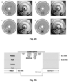
- One or more light sources, preferably LEDs may be provided under the sample chamber. This allows strobe photography of the microfluidic channels synchronized with the rotation of the platform by a camera placed above the rotating platform (see Fig. 17 ). This is important as the photos can be used in the analysis of the process and results of the sample under investigation.
- the device may be configured such that the rotation platform is capable of having a rotational speed of at least 5 RPM, more preferably at least 20 RPM, yet more preferably at least 100 RPM, even more preferably at least 1000 RPM, most preferably at least 3000 RPM, for example between 10 and 100 RPM.
- the mobile centrifugal microfluidic device may comprise at least one light source, such as an LED, on the platform for illuminating the sample. This makes imaging of the microfluidic channels much easier.
- the device may be configured such that the rotation platform is capable of having a stable rotational speed of less than 100 RPM, or less than 80 RPM, most preferably around or less than 60 RPM.
- the present disclosure further relates to a mobile microfluidic system possibly including a software solution.
- the system may comprise the presently disclosed mobile microfluidic device and a software solution executable on an external device for controlling and monitoring the device and sample analysis from the external device.
- the software application of the system may be configured to synchronize a camera on the remote device, such as a smartphone, and optionally a light source on the remote device and/or on mobile centrifugal microfluidic device with the rotation of the platform for strobe photography of the sample during rotation of the platform. This enables the system to integrate the information provided from the strobe photography in a single user interphase and use the information provided from the images to control the device.
- the software application may also be configured for receiving sensing results and/or for controlling and/or monitoring of the rotational speed of the platform.
- the analysis results and operational parameters of the mobile microfluidic device can be read out to an external device possible with a user friendly interface such as an app interface.
- the mobile centrifugal microfluidic device may use equipment from the external device such as the camera or LED light from a smartphone which may be desirable in the process of analysis.
- a test has shown that a typical state-of-the-art commercial smartphone's camera is suitable for strobe photography. High quality images of a rotating platform acquired with very short exposure time of 1/10000, 1/20000, 1/50000 seconds and only illuminated with smartphone's built-in light source, showed that such imaging can be applied even for high spinning speeds of the platform.
- the present disclosure further relates to a centrifugal microfluidic disc for in vitro studies of microorganisms, such as bacterial cells, or mammalian cells.
- the platform may be used for studying a wide range of microorganisms such as bacteria, archaea, protozoa, algae, fungi, viruses, or multicellular eukaryotes. As an example, it may be used for studying the growth of bacteria in the culture chamber.
- the bacteria typically forms a biofilm.
- the growth of this biofilm may be studied under the variation of a number of parameters e.g. the amount of nutrients available to the bacteria, and the flow-rate of the nutrient flow passing through the sample chamber. Different materials for the surface that the biofilm forms on might also be investigated.
- static cell culture models typically include culturing cells in a petri dish, whereas the latter studies the cells under the influence of flow.
- static models typically do not represent or mimic an environment that is similar to e.g. a human body, wherein the bacteria is under the influence of a flow.
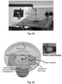
- Perfusion models provide a more realistic environment; however, they often require large experimental setups such as the one shown in Fig. 26 .
- centrifugal microfluidic platform provides a much smaller experimental platform (e.g. having the footprint of a compact disc) by integrating some of the components, e.g. the inlet and outlet reservoir and the microfluidic channels, whereas other components such as the external pump may be avoided and replaced by a simple spinning motor ( Figure 22 ).
- the centrifugal microfluidic disc is included in the bottom left of Fig. 26 for size comparison. The spinning of the disc and the resulting centrifugal force obviates the need for a pump. Furthermore, the applicant has found that by spinning the disc at a certain frequency, the flow rate in the channels can be controlled accordingly (cf. Fig. 44 ).
- a very constant and low flow-rate can be achieved for a constant rotational frequency, said low constant flow-rate being important in some applications such as long term growth of bacterial and mammalian cells.
- the controlled flow-rate is achieved by a combination of the features on the disc and the rotational frequency of the disc.
- the centrifugal microfluidic platform constitutes a lab-on-a-disc unit as shown in figure 19 .
- the lab-on-a-disc comprises multiple features including an inlet reservoir, an inlet channel, a culture chamber, an inoculation channel, an effluent channel, and an outlet reservoir. It may further comprise a lid placed on top of the culture chamber to seal the chamber.
- the lid allows bacteria to grow in the top of the chamber on the surface of the lid facing the inside of the chamber.
- the design of the chamber allows the perfusion of nutrients and oxygen via a flow through the chamber. In case of a bacterial biofilm formed on the lid, the flow reaches the bacterial cells from below.
- the lid is preferably transparent, such that the formation of a biofilm on the surface of the lid can be detected from the outside e.g. using a microscope. Since the biofilm forms at the top of the culture chamber, this detection and/or imaging is optimized.
- Another advantage of configuring the culture chamber for bacterial growth at the top of the chamber is that the bacteria then do not create occlusions close to the inlet and outlet of the chamber, provided said inlet/outlet are placed at the bottom of the chamber (see figure 29 ).
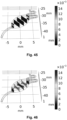
- Yet another advantage is that the bacteria is not affected by shear stress. The influence of the flow-rate and shear stress has been investigated through numerical simulations and found not to affect the growth of the bacteria negatively (cf. simulation results shown in Fig. 45-46 ).
- the disc may further comprise a plurality of openings for accessing said reservoirs or channels.
- the disc comprises three openings: One inlet opening, one inoculation inlet, and one opening to the outlet reservoir.
- the inlet and outlet reservoirs resemble the arc of a circle, wherein the center of the circle is located at the center of the disc.
- the inlet reservoir is placed near the center of the disc, while the outlet reservoir is placed near the edge of the disc.
- the microfluidic platform is preferably configured such that the two reservoirs, the inlet reservoir and the outlet reservoir, are separated by a constant radial distance (see e.g. Fig. 27 or Fig. 41 ).
- a uniform radial distance ensures that the pressure difference between the inlet reservoir and the outlet reservoir will be constant during rotation of the platform as well. This is important, since the centrifugal force and the resulting pressure difference is the driving force of the liquid moving from the inlet reservoir towards the outlet reservoir.
- the design of the microfluidic platform facilitates a constant flow rate for a given rotational frequency, which is important for experiments carried out in the cell chamber.
- the configuration allows for the placement of one or more culture chambers between the two reservoirs, wherein the culture chambers are fluidly connected to the two reservoirs. It further allows that a liquid may flow at a constant flow rate from the inlet reservoir to the outlet reservoir via the culture chamber, provided the disc is rotated such that the liquid is forced to flow towards the edge of the disc due to centrifugal forces.
- the inlet reservoir is preferably able to store a large volume of liquid compared to the volume of the culture chamber, such as at least 10, or at least 30 times, preferably at least 50 times as much as the culture chamber.
- the volume of the inlet reservoir is at least 1 mL.
- the inlet reservoir can hold approximately 3 mL of liquid and the culture chamber can hold approximately 55 ⁇ L.
- In the first end of the inlet reservoir there is preferably an opening to the outside such that liquid may be added to the inlet reservoir e.g. using a syringe. Subsequent to filling the reservoir with liquid, the opening may be closed again e.g. using a filter.
- each opening is provided with a Luer connector configured for engaging with either a syringe or a filter.
- the Luer connectors and filters are visible on Fig. 21 .
- the reservoir connects with an inlet channel of smaller dimensions.
- the inlet channel serves the purpose of providing a larger fluidic resistance and thereby slowing the speed of a liquid flowing during an experiment.
- the inlet channel is formed as a serpentine channel.
- An advantage of this particular shape of the inlet channel is that it allows a better mixing of nutrients.
- the culture chamber is designed to resemble an oval shape in order to avoid sharp edges and trapping of air bubbles. It is mainly the cross-sectional area of the inlet channel coupled with the rotational speed and the size of the disc that controls the flow of liquid into the culture chamber.
- the inlet and outlet channels are preferably placed near the bottom of the culture chamber to provide enough space for bacterial biofilm growth and to allow continuous perfusion of nutrients (see Fig. 29 ).
- the embodiment of the platform designed for bacterial growth preferably further features a cover glass to close the cell chamber in order to have an optimal surface for bacteria adhesion and good quality imaging e.g. using scatter confocal scanning laser microscopy.
- the cell culture chamber is suitable for cell culturing.
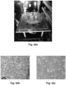
- the culture chamber is designed to facilitate growth of adherent cells on the bottom of the culture chamber (cf. Fig. 43 ).
- This design is optimized to facilitate the accommodation and growth of mammalian cells. This is achieved by placing the inlet and outlet of the culture chamber at the top of the chamber, such that the flow through the culture chamber does not stress the cells and thereby negatively affect the cell growth. This is crucial for mammalian cells, since they are more easily affected by flow.
- the liquid flow containing nutrients and oxygen reaches the cells from the top, while avoiding a large flow velocity across the surface of the cells. Using mathematical and physical simulations, it was found that the shear stress and the flow rate were of sufficiently low values such that they do not affect the growth of the bacteria negatively.
- Figures 45-48 show results from the simulation. Furthermore, in this application there is no need for a cover glass. Instead, a whole layer such as a PMMA layer may constitute a lid of the mammalian culture chamber. This lid is preferably transparent, such that optical observation may be performed through the lid.
- the inoculation channel serves the purpose of allowing the placement of an inoculum, such as a diluted bacteria culture or mammalian cells in suspension, in the culture chamber. In a preferred embodiment, this is achieved by dimensioning the inoculation channel such that a syringe needle may enter the culture chamber via the inoculation channel. Then, the inoculum may be delivered by the syringe (cf. figure 28 ).
- the inoculation channel preferably features an opening in the proximal end such that the channel may be accessed from the outside.
- Fig. 30 shows how an injection needle may be inserted through such an opening (the inoculation inlet). The needle can preferably fit inside the channel such that it can be pressed through the entirety of said channel and reach the sample chamber. Subsequent to inoculation, the opening may be closed using a combination of a Luer connector and a filter, as previously described.
- the effluent channel serves the purpose of connecting the culture chamber with the outlet reservoir. Thus, it facilitates the passage of waste and clusters.
- the effluent channel is an approximately straight channel or slightly curved channel. The effect of this geometry is that the channel ensures that no clogging occurs such that waste is efficiently transported to the waste/outlet reservoir.
- the disc is configured for engaging with a rotatable platform or a spinning motor such that the disc may be rotated (see Fig. 24 ).
- the means for engaging with a rotatable platform may be a central hole in the disc.
- the lab-on-a-disc is suitable for stacking with other similar lab-on-a-discs as shown on figure 23 .
- the disc is configured for the integration of one or more modules with the platform. Such modules may include an optical microscope, a camera, an electrochemical analyzer, a potentiostat, or a miniaturized Raman system (cf. figure 25 ).
- the following is an example of how to fabricate a centrifugal microfluidic disc according to the present disclosure.
- the embodiment described in the following is particularly well suited for culturing bacterial cells and for the study of biofilm formation.
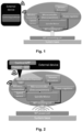
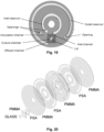
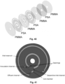
- the disc comprises eight layers, namely four layers of poly(methyl methacrylate) (PMMA), three layers of pressure sensitive double adhesive tape (PSA) and one layer of glass (see Fig. 20 ).
- the disc has a 100 mm outer diameter and a of 15.35 mm inner diameter.
- the biological disc was fabricated using two layers of 0.60 mm thick PMMA, one layer of 5 mm thick PMMA, and two layers of 0.15 mm thick PSA.
- a 20 x 20 mm 2 layer of 0.60 mm thick PMMA, together with a 20 x 20 mm 2 layer of 0.15 mm thick PSA and 18 x 18 mm 2 layer of 0.15 mm thick cover glass were designed to maximize the culture volume and the detection.
- the PMMA layers were fabricated using laser ablation technique except for the channels and the culture chamber, which were fabricated using micromilling.
- PMMA layers, previously cleaned with sonication and ethanol, and PSA layers were assembled using a bonding press with a force of 10 KN in order to maximize the adhesion and to remove possible bubbles between layers.
- the cover glass was separately glued using a silicone glue and dried overnight. Filters with a 3 mm diameter membrane and pore size of 0.20 ⁇ m were used to maintain the sterile environment in the disc while keeping the oxygen flow in the platform through the pores.
- Luer connectors were fabricated in cyclic olefin-copolymer (COC) polymer using injection molding. Luer connectors were fixed on venting and loading holes facilitating the introduction of filters.
- the assembled centrifugal microfluidic disc can be seen in figure 21 .
- the centrifugal microfluidic disc may be fabricated using other manufacturing methods for fabricating lab-on-a-discs.
- the microfluidic disc may be fabricated using injection moulding, which is suitable for industrial scale production of the disc.
- the fabrication of the disc may be carried out using only laser ablation and subsequently assembled using an adhesive layer, e.g. PSA.
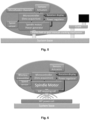
- the disc for culturing mammalian cells may comprise seven layers of alternating PMMA and PSA layers as shown on Fig. 40 . The layers are preferably bonded together to form a single unit, such that the layers are permanently fixed to each other. Notice that this embodiment does not need a lid or a cover glass on top of the culture chamber as shown in Fig. 19-20 . On the contrary, the mammalian culture chamber is enclosed entirely in the microfluidic disc once it is manufactured, such that the only access from the outside to the chamber is via the openings in the disc, preferably via the inoculation channel.
- the following is an example of how to set up an experiment using the centrifugal microfluidic disc according to the present disclosure.
- the entire system including the microfluidic channels is sterilized.
- the system was filled with a medium and left overnight at a low flow rate (pump set on 0.5 RPM, around 60 ⁇ L/min).
- the inoculation of the bacteria in the sterilized disc was achieved by addition of 40 ⁇ L overnight culture of 1:100 diluted P. aeruginosa though the inoculation channel situated in close proximity to the cell culture chamber (see figure 30 ).
- the loading opening was closed to create a backpressure avoiding bacteria occlusion in the serpentine channel.
- the adhesion of the bacteria in the culture chamber was carried out in stop flow for one hour, followed by rotation at the set frequency.
- the total volume of the cell chamber is around 55 ⁇ L and only 40 ⁇ L of PAO1 was inoculated in order to prevent the introduction of bacteria in the inlet channel.
- the inoculation in the flow system was achieved by stopping the pump and adding 250 ⁇ L overnight culture of 1:100 diluted P. aeruginosa in the selected channels in proximity of the flow chamber. It was important to clamp the silicone tubes which were feeding the channels in order to avoid a back flow.
- the tubes were sterilized with ethanol before inoculation and the inoculation hole sealed with silicone glue after it.
- the adhesion of the bacteria in the flow chip was carried out in stop flow for one hour and with the chip turned upside down. After one hour, clamps were removed and the flow started.
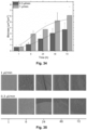
- the bacteria were cultured for 72 hours in order to form a mature biofilm before introducing the antibiotic in the culture medium.
- Propidium iodide was used as a DNA stain to evaluate biofilm viability, since it binds to the nucleus of dead cell making them fluoresced red. 2 ⁇ L of pure propidium iodide was introduced in the inlet reservoir. The percentage of alive bacteria in the biofilm was between 80 - 90% of the total biomass before treatment.
- Ciprofloxacin with a final concentration of 4 ⁇ g/mL was introduced and diluted with medium and propidium iodide in the inlet reservoir.
- Antibiotic and propidium iodide were introduced with the help of a pipette through the loading hole, avoiding to create pressure on biofilm.
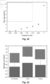
- the obtained calibration curve with culture medium is presented recorded using a sterilized lab-on-a-disc according to the present disclosure.
- the calibration curve was constructed from the images taken in the inlet reservoir at a defined time (depending on the frequency). Each data point was taken three times.
- the calculation of the flow rate, volume of the liquid, was calculated using a computer code. It can be seen that the flow rate can be accurately controlled in the linear range between 55 nL/min and 2 ⁇ L/min with a variation below 15 %. It was also found that the variation between different platforms was around 10 %, based on three number of tested devices. Additionally, the stability of the flow rate over time was investigated for up to 72 hours, wherein a variation of approximately 5 % was determined.
- 3D computational fluid dynamics (CFD) simulations were used to mimic the fluid flow through the culture chamber in three spatial dimensions and to calculate the resulting shear stress at the top of the sample chamber.
- the numerical simulations rely on the equation for continuity being considered along with Navier-Stokes equations.
- the model for the numerical simulations was build assuming a steady state flow, presence of incompressible Newtonian fluid, negligible Coriolis force and Stokes flow (negligible inertial term). From these considerations, the Navier-Stokes equations could be reduced to the Stokes equation.
- the boundary conditions used in the simulations include no-slip boundary conditions at the walls, experimentally measured flow velocity at the inlet, and 0 Pa gauge pressure at the outlet.
- a numerical model was used to evaluate the shear stress in the cell chamber. Relying on the experimentally measured flow rates as input, the shear stress was calculated as the product of the shear rate and dynamic viscosity of the fluid. Additionally, it was assumed that the shear stress effect on the biofilm is either equal to or lower than the wall shear stress, (shear stress at the edges of the cell chamber), in the top part of the cell chamber.
- the values of interest are the average and maximum wall shear stress. It was found that the maximum shear stress occurs in the cell chamber just after the inlet and just before the outlet.
- the calculated maximum shear stress is approximately an order of magnitude higher than the average shear stress in the cell culture chamber, while the highest calculated shear stress at 2 ⁇ L/ min (0,8 Hz) is 0.6 mPa. Based on our calculations, the bacteria growing in the cell culture chamber are exposed to a rather low shear stress. Thus, it can be concluded that the flow rate used to operate the platform will not negatively affect the cells on the biofilm formation.
- the biofilm and the surrounding media within the cell chamber are also exposed to centrifugal forces.
- the biofilm will either experience a force inwards or outwards from the center.
- the centrifugal buoyancy force was assessed that the centrifugal forces became lower as the buoyant density of the cells become more similar to the surrounding medium.
- the buoyant density of bacterial cells is approximately the same as the surrounding media M9, therefore at the low angular velocities (flow rates between 0.3 ⁇ L/min to 1 ⁇ L/min) used in this platform, the forces acting upon the cells and surrounding medium will be almost equivalent.
- the centrifugal force has a negligible effect on the formation of a biofilm in the chamber. It is worth mentioning that sufficiently high angular velocity, thousands of g-forces (gravitational acceleration), will cause the buoyant force to be large enough to have a significant effect.
- the microfluidic platform was rotated at 1 Hz (6.28 rad/s) to evaluate the centrifugal force. At a distance from the center of rotation of 32 mm (in the center of the cell chamber), the relative centrifugal force in the platform was only 0.128 g, meaning that the cells and surrounding media will experience an acceleration out from the disc equal to about 13% of earths gravitational acceleration.
- the contribution of convective mass transport can be quantified using the non-dimensional Péclet number, which corresponds to the Reynolds number multiplied by the Schmidt number.
- the Schmidt number is large (approximately 500), resulting in the Péclet number being orders of magnitude larger than the Reynolds number, meaning that the nutrients transport depend primarily on the flow rate.
- the Péclet number for the range of Reynolds numbers used in this study will be in the order of 10 to 100 in respect of the lowest and highest flow rate used to culture bacteria in the experiments.
- the lab-on-a-disc was sterilized using a similar procedure already described for the bacterial culture.
- the mammalian culture medium contains proteins, which could lead to foaming and bubble formation in the flow, no bubble formation was observed in the microfluidic system.
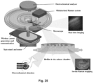
- the mammalian culture platform was placed in an incubator (see Fig. 42a ) to precisely control the temperature and gas composition as well as the humidity of the environment surrounding the microfluidic platform, is shown in Figure 40 or 41 .
- the photograph also shows the compactness of the system, and that the platform is compatible to be used for long-term cell culture in a standard incubator.
- the present disclosure further relates to a method for monitoring microorganisms, such as cells, bacteria, etc., in particular mammalian cells, preferably under the constant supply of nutrients, thereby mimicking in vivo conditions.
- a method for monitoring microorganisms such as cells, bacteria, etc., in particular mammalian cells, preferably under the constant supply of nutrients, thereby mimicking in vivo conditions.
- Such a method can be advantageously be executed using the presently disclosed centrifugal microfluidic disc and the presently disclosed mobile (i.e. portable) centrifugal microfluidic device.
- One embodiment relates to a method for monitoring cells, such as bacterial cells or mammalian cells, comprising the step of inoculating the cells in a culture chamber in a rotatable platform, such as the presently disclosed centrifugal microfluidic disc, the cells may be in a liquid solution comprising nutrients, rotating the platform such that liquid in a reservoir connected to or located on the platform, the liquid comprising nutrients for the cells, is constantly supplied to the culture chamber by means of shear / centrifugal force resulting from rotating the platform, the platform preferably rotating at a constant rotation rate.
- the effluent from the culture chamber can be transported to an outlet reservoir, e.g. by means of an effluent channel. These may also be located on the platform as herein described.
- the rotation rate is preferably less than 10 Hz, more preferably less than 5 Hz, even more preferably less than 2 Hz, most preferably around 1 Hz.
- the liquid flow rate through the culture chamber is preferably constant by means of constant rotation of the platform.
- the liquid flow rate may be between 5 nL/min and 10 ⁇ L/min, preferably less than 5 ⁇ L/min, more preferably less than 2 ⁇ L/min, even more preferably less than 1 ⁇ L/min, most preferably less than 0.5 ⁇ L/min.
- Such conditions of low rotation rate and constant supply of nutrients can ensure that the cells can be monitored under mimicked in-vivo conditions for at least 6 hours, more preferably at least 12 hours, even more preferably at least 24 hours, most preferably at least 48, and even more than 96 hours.
- microorganisms can be monitored simultaneously, for example by having several culture chambers on the same disc and/or by having multiple discs mounted on top of each and rotated by the same platform.
- the cells can be monitored by imaging, electrochemical, electrical, etc., e.g. by means of suitable devices mounted on the rotating platform. Rotation of the platform and/or monitoring of the cells by means of imaging, electrochemical, electrical, etc., can be provided by means of the presently disclosed portable LoD device.
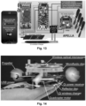
- FIG. 7 shows a schematic illustration of an example of the presently disclosed powered lab-on-a-disc (PLoD) device:
- a miniaturized wireless optical microscope of the PLoD platform which integrates a 2.4 GHz Wi-Fi transmitter, a complementary metal-oxide-semiconductor (CMOS, 1920 x 1080 pixels) sensor, with a high numerical aperture optics and a wireless inductive "Qi" energy transmission interface 4 .
- the motor is not show in fig. 7 .
- CMOS complementary metal-oxide-semiconductor
- Qi wireless inductive
- the wireless microscope imaging parameters such as resolution (1920x1080/1280x720), exposure time, modes switching (color/infrared) and photo/video capture time interval (from 15 minutes to 24 hours) can be controlled by a mobile application. Furthermore, four wireless microscopes can be monitored by the single mobile device or PC at the same time.
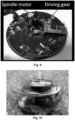
- Fig. 9 is a photo of one example of integration of a spindle motor on a rotatable platform.
- the spindle motor is mounted with the drive shaft parallel to the axis of rotation of the platform but slightly displaced therefrom.
- the platform is in the form of a disk.
- a driving gear engaged with the drive shaft of the spindle motor and the rotation axis of the platform provides for transferal of the mechanical energy of the motor to rotation of the disk. Gearing is provided to better utilize the torque of the spindle motor, which for small motors are often quite small.
- Electronic components are also visible in fig. 9 distributed all over the platform.
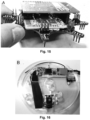
- Fig. 10 shows a photo of a truly mobile example of the presently disclosed centrifugal microfluidic device with a motor integrated on the rotating platform, the motor is not visible. It is shown rotating in a grass field and is powered by a wireless mobile charger.
Landscapes
- Chemical & Material Sciences (AREA)
- Health & Medical Sciences (AREA)
- Life Sciences & Earth Sciences (AREA)
- General Health & Medical Sciences (AREA)
- Analytical Chemistry (AREA)
- Physics & Mathematics (AREA)
- Biochemistry (AREA)
- Chemical Kinetics & Catalysis (AREA)
- General Physics & Mathematics (AREA)
- Immunology (AREA)
- Pathology (AREA)
- Molecular Biology (AREA)
- Dispersion Chemistry (AREA)
- Hematology (AREA)
- Clinical Laboratory Science (AREA)
- Electrochemistry (AREA)
- Nuclear Medicine, Radiotherapy & Molecular Imaging (AREA)
- Fluid Mechanics (AREA)
- Apparatus Associated With Microorganisms And Enzymes (AREA)
Claims (17)
- Zentrifugalmikrofluidik-Scheibe, umfassend:- ein Einlassreservoir;- mindestens einen Einlasskanal;- mindestens eine Probenkammer für In-vitro-Untersuchungen von Mikroorganismen;- mindestens einen Auslasskanal; und- ein Auslassreservoir;wobei die Mikrofluidik-Scheibe für den Eingriff mit einer rotierbaren Plattform oder einem Motor zum Drehen der Mikrofluidik-Scheibe konfiguriert ist, und wobei die Scheibe so konfiguriert ist, dass während der Rotation der Scheibe Flüssigkeit in dem Einlassreservoir durch Zentrifugalkraft nach außen gedrückt wird, so dass Flüssigkeit kontrolliert von dem Einlassreservoir zu dem Auslassreservoir über 1) den Einlasskanal, 2) die Probenkammer und 3) den Ausflusskanal übertragen werden kann, wobei die Geometrie des Einlassreservoirs einem Bogen eines ersten Kreises und die des Auslassreservoirs einem Bogen eines zweiten Kreises ähnelt, wobei der Mittelpunkt des ersten und zweiten Kreises in der Mitte der Scheibe liegt und wobei das Volumen des Einlassreservoirs mindestens 1 ml beträgt.
- Zentrifugalmikrofluidik-Scheibe nach Anspruch 1, wobei das Einlassreservoir und/oder das Auslassreservoir mit einer Öffnung zum Übertragen einer Flüssigkeit in oder aus dem Reservoir versehen ist.
- Zentrifugalmikrofluidik-Scheibe nach einem der vorhergehenden Ansprüche, wobei der Einlasskanal zwischen dem Einlassreservoir und der/den Probenkammer(n) mindestens eine Serpentine umfasst, um die Durchmischung von Nährstoffen, die sich in einer durch den Einlasskanal strömenden Flüssigkeit befinden, zu erhöhen.
- Zentrifugalmikrofluidik-Scheibe nach einem der vorhergehenden Ansprüche, wobei das Volumen des Einlassreservoirs mindestens 3 ml oder 5 ml beträgt.
- Zentrifugalmikrofluidik-Scheibe nach einem der vorhergehenden Ansprüche, wobei das Volumen der Probenkammer(n) zwischen 1 und 100 µl, bevorzugter zwischen 10 und 80 µl, am meisten bevorzugt zwischen 45 und 65 µl liegt.
- Zentrifugalmikrofluidik-Scheibe nach einem der vorhergehenden Ansprüche, die so konfiguriert ist, dass sie eine konstante Flüssigkeitsflussrate durch die Probenkammer von zwischen 10 nl/min und 5 µl/min aufweist, wenn die Mikrofluidik-Scheibe mit einer konstanten Frequenz von weniger als 10 Hz rotiert wird.
- Zentrifugalmikrofluidik-Scheibe nach einem der vorhergehenden Ansprüche, ferner umfassend einem Inokulationskanal zum Einbringen eines Inokulums in die Probenkammer.
- Zentrifugalmikrofluidik-Scheibe nach einem der vorhergehenden Ansprüche, wobei die Scheibe durch Stapeln von Schichten aus Polymer und Klebstoff hergestellt wird.
- Zentrifugalmikrofluidik-Scheibe nach einem der vorhergehenden Ansprüche, wobei das Einlassreservoir und/oder der Einlasskanal so konfiguriert sind, dass eine konstante Flussrate der vom Einlassreservoir in die Probenkammer fließenden Flüssigkeit ermöglicht wird, vorausgesetzt, die Mikrofluidik-Scheibe wird mit einer konstanten Rotationsgeschwindigkeit rotiert.
- Zentrifugalmikrofluidik-Scheibe nach einem der vorhergehenden Ansprüche, wobei eine Querschnittsfläche des Einlasskanals die Flussrate einer Flüssigkeit bestimmt, die aus dem Einlassreservoir in die Probenkammer bei einer vorgegebenen Rotationsgeschwindigkeit der Scheibe fließt.
- Zentrifugalmikrofluidik-Scheibe nach einem der vorhergehenden Ansprüche, wobei die Scheibe eine Vielzahl von Probenkammern umfasst, wie beispielsweise mindestens zwei oder mindestens drei.
- Zentrifugalmikrofluidik-Scheibe nach Anspruch 11, wobei die Scheibe ferner einen Inokulationskanal pro Probenkammer umfasst, so dass jede Probenkammer separat inokuliert werden kann.
- Zentrifugalmikrofluidik-Scheibe nach einem der Ansprüche 11-12, wobei ein einziger Einlasskanal die Vielzahl von Probenkammern mit dem Einlassreservoir verbindet.
- Tragbare Zentrifugalmikrofluidik-Vorrichtung, die für In-vitro-Untersuchungen von Mikroorganismen, wie z. B. Zellen, konfiguriert ist, wobei die Vorrichtung Folgendes umfasst- eine Stützbasis zum Stützen der Vorrichtung auf einer Oberfläche,- eine rotierbare Plattform auf der Oberseite der Basis, die so konfiguriert ist, dass sie in Bezug auf eine Achse senkrecht zur Basis rotiert,- mindestens einen Motor, der auf der rotierbaren Plattform integriert ist, um die Plattform zu rotieren, und- eine Zentrifugalmikrofluidik-Scheibe nach einem der vorhergehenden Ansprüche.
- Verwendung der Zentrifugalmikrofluidik-Scheibe nach einem der vorhergehenden Ansprüche 1-13 zum Züchten von Zellen, wie Bakterien und/oder Säugetierzellen, in der mindestens einen Probenkammer unter dem Einfluss eines Flüssigkeitsstroms von Nährstoffen, wobei der Flüssigkeitsstrom mittels Zentrifugalkräften erzeugt wird, die während der Rotation der Zentrifugalmikrofluidik-Scheibe entstehen, wobei die Rotation mit einer Rotationsrate von weniger als 10 Hz, bevorzugter weniger als 5 Hz, noch bevorzugter weniger als 2 Hz, am meisten bevorzugt um 1 Hz, erfolgt.
- Verwendung der Zentrifugalmikrofluidik-Scheibe nach einem der vorhergehenden Ansprüche 1-13 zur Überwachung von Mikroorganismen, beispielsweise während des Wachstums von Zellen, wobei die Mikroorganismen mittels bildgebender, elektrochemischer und/oder elektrischer Messungen während der Rotation der Zentrifugalmikrofluidik-Scheibe überwacht werden, wobei die Rotation mit einer Rotationsrate von weniger als 10 Hz, bevorzugter weniger als 5 Hz, noch bevorzugter weniger als 2 Hz, am meisten bevorzugt um 1 Hz, erfolgt.
- Verwendung der Zentrifugalmikrofluidik-Scheibe nach einem der vorhergehenden Ansprüche 1-13 zur Durchführung von In-situ-Raman-Mapping einer oder mehrerer Proben, die in der mindestens einen Probenkammer auf der Mikrofluidik-Scheibe enthalten sind, wobei die Scheibe ein miniaturisiertes Raman-System umfasst.
Applications Claiming Priority (3)
| Application Number | Priority Date | Filing Date | Title |
|---|---|---|---|
| EP18202261 | 2018-10-24 | ||
| PCT/EP2019/079115 WO2020084099A1 (en) | 2018-10-24 | 2019-10-24 | Multi function spinning platform |
| EP19795169.2A EP3870366A1 (de) | 2018-10-24 | 2019-10-24 | Multifunktionale spinnplattform |
Related Parent Applications (1)
| Application Number | Title | Priority Date | Filing Date |
|---|---|---|---|
| EP19795169.2A Division EP3870366A1 (de) | 2018-10-24 | 2019-10-24 | Multifunktionale spinnplattform |
Publications (3)
| Publication Number | Publication Date |
|---|---|
| EP3967403A1 EP3967403A1 (de) | 2022-03-16 |
| EP3967403C0 EP3967403C0 (de) | 2024-05-01 |
| EP3967403B1 true EP3967403B1 (de) | 2024-05-01 |
Family
ID=63965483
Family Applications (2)
| Application Number | Title | Priority Date | Filing Date |
|---|---|---|---|
| EP21206026.3A Active EP3967403B1 (de) | 2018-10-24 | 2019-10-24 | Multifunktionale spinnplattform |
| EP19795169.2A Pending EP3870366A1 (de) | 2018-10-24 | 2019-10-24 | Multifunktionale spinnplattform |
Family Applications After (1)
| Application Number | Title | Priority Date | Filing Date |
|---|---|---|---|
| EP19795169.2A Pending EP3870366A1 (de) | 2018-10-24 | 2019-10-24 | Multifunktionale spinnplattform |
Country Status (5)
| Country | Link |
|---|---|
| US (2) | US12168228B2 (de) |
| EP (2) | EP3967403B1 (de) |
| AU (2) | AU2019363719C1 (de) |
| CA (2) | CA3117090C (de) |
| WO (1) | WO2020084099A1 (de) |
Families Citing this family (4)
| Publication number | Priority date | Publication date | Assignee | Title |
|---|---|---|---|---|
| CN114088772A (zh) * | 2021-11-11 | 2022-02-25 | 同济大学 | 放置脑片的实验设备 |
| DE102022106693B3 (de) * | 2022-03-22 | 2023-03-16 | Dermagnostix GmbH | Centrifugal Microfluidic Biochip |
| CN114509575B (zh) * | 2022-04-19 | 2022-06-14 | 天津德祥生物技术有限公司 | 微流控检测装置 |
| WO2025251064A1 (en) * | 2024-05-30 | 2025-12-04 | Goltech Llc | Automated microfluidic device for real-time monitoring of material swelling characteristics |
Family Cites Families (11)
| Publication number | Priority date | Publication date | Assignee | Title |
|---|---|---|---|---|
| US6709869B2 (en) | 1995-12-18 | 2004-03-23 | Tecan Trading Ag | Devices and methods for using centripetal acceleration to drive fluid movement in a microfluidics system |
| GB9808836D0 (en) * | 1998-04-27 | 1998-06-24 | Amersham Pharm Biotech Uk Ltd | Microfabricated apparatus for cell based assays |
| WO2001087486A2 (en) * | 2000-05-15 | 2001-11-22 | Tecan Trading Ag | Microfluidics devices and methods for performing cell based assays |
| US20050287536A1 (en) * | 2004-06-24 | 2005-12-29 | Douglas Kozlay | Disposable, multi-use, DNA sample collection disk apparatus for field biohazard testing, DNA testing, and personal authentication |
| WO2006060822A2 (en) | 2004-12-03 | 2006-06-08 | Mattel, Inc. | Digital rights management compliance with portable digital media device |
| EP2046992B1 (de) * | 2006-08-02 | 2013-04-03 | Samsung Electronics Co., Ltd. | Chemisches dünnschichtanalysegerät mit berstmembran ventil |
| US7993583B2 (en) * | 2008-10-29 | 2011-08-09 | Lawrence Livermore National Security, Llc | Passive microfluidic array card and reader |
| KR20100101526A (ko) | 2009-03-09 | 2010-09-17 | 삼성전자주식회사 | 스트로보 박막 화학 분석 장치 및 이를 이용한 분석 방법 |
| CA2840126A1 (en) * | 2011-07-04 | 2013-01-10 | National Research Council Of Canada | Centrifugal microfluidic platform |
| WO2017070607A1 (en) | 2015-10-23 | 2017-04-27 | Landers James P | Systems, devices and methods for analyzing and identifying substances |
| US10065187B2 (en) | 2016-02-12 | 2018-09-04 | Schlumberger Technology Corporation | Centrifugal platform and device for rapid analysis of oilfield fluids |
-
2019
- 2019-10-24 EP EP21206026.3A patent/EP3967403B1/de active Active
- 2019-10-24 EP EP19795169.2A patent/EP3870366A1/de active Pending
- 2019-10-24 CA CA3117090A patent/CA3117090C/en active Active
- 2019-10-24 WO PCT/EP2019/079115 patent/WO2020084099A1/en not_active Ceased
- 2019-10-24 AU AU2019363719A patent/AU2019363719C1/en active Active
- 2019-10-24 US US17/288,152 patent/US12168228B2/en active Active
- 2019-10-24 CA CA3237941A patent/CA3237941A1/en active Pending
-
2021
- 2021-12-20 US US17/555,691 patent/US12220703B2/en active Active
- 2021-12-20 AU AU2021290218A patent/AU2021290218B2/en active Active
Also Published As
| Publication number | Publication date |
|---|---|
| AU2019363719C1 (en) | 2025-01-02 |
| EP3967403A1 (de) | 2022-03-16 |
| EP3967403C0 (de) | 2024-05-01 |
| US20220008923A1 (en) | 2022-01-13 |
| CA3117090A1 (en) | 2020-04-30 |
| US12168228B2 (en) | 2024-12-17 |
| AU2021290218B2 (en) | 2023-12-07 |
| AU2019363719B2 (en) | 2023-10-26 |
| EP3870366A1 (de) | 2021-09-01 |
| AU2021290218A1 (en) | 2022-01-20 |
| US20220111384A1 (en) | 2022-04-14 |
| AU2019363719A1 (en) | 2021-05-27 |
| US12220703B2 (en) | 2025-02-11 |
| CA3237941A1 (en) | 2020-04-30 |
| CA3117090C (en) | 2024-06-18 |
| WO2020084099A1 (en) | 2020-04-30 |
Similar Documents
| Publication | Publication Date | Title |
|---|---|---|
| US12220703B2 (en) | Multi function spinning platform | |
| Iakovlev et al. | Novel pumping methods for microfluidic devices: a comprehensive review | |
| US12110484B2 (en) | Disposable bioprocess system supporting biological activity | |
| Skafte-Pedersen et al. | A self-contained, programmable microfluidic cell culture system with real-time microscopy access | |
| US9528082B2 (en) | Modular platform for multi-tissue integrated cell culture | |
| Zhang et al. | Microbioreactors for bioprocess development | |
| CN101835886A (zh) | 用于灌注的中等尺寸生物反应器平台 | |
| EP2951282A1 (de) | Modulare plattform für eine in mehrere gewebe integrierte zellkultur | |
| US20190322972A1 (en) | Methods and apparatus for perfusion and environment control of microplate labware | |
| Sønstevold et al. | Application of polymethylpentene, an oxygen permeable thermoplastic, for long-term on-a-chip cell culture and organ-on-a-chip devices | |
| WO2010131715A1 (ja) | 培養装置 | |
| Schneider et al. | Organ-on-a-disc: A platform technology for the centrifugal generation and culture of microphysiological 3D cell constructs amenable for automation and parallelization | |
| US20250257300A1 (en) | Microtiter-plate-based high throughput perfusion bioreactor | |
| Sun et al. | Reusable standardized universal interface module (RSUIM) for generic organ-on-a-chip applications | |
| Sonntag et al. | Universal lab-on-a-chip platform for complex, perfused 3D cell cultures | |
| McLeod et al. | A standard 96-well based high throughput microfluidic perfusion biofilm reactor for in situ optical analysis | |
| Agarwal et al. | A Modular, Cost-Effective, and Pumpless Perfusion Assembly for the Long-Term Culture of Engineered Microvessels | |
| Amani Wan Salim et al. | Lab-on-a-chip approaches for space-biology research | |
| Srinivasan et al. | A Live Cell Imaging‐Compatible Bioreactor for the Interrogation of Cellular Responses to Modulated Flow Conditions | |
| WO2024191784A1 (en) | Multi-well plate flow culture system for improving the quality of 3d tissues | |
| Böhme et al. | Miniaturized flow-through bioreactor for processing and testing in pharmacology | |
| Tsai | Highly parallel microbioreactors for cell line development based on well plates with functional lids | |
| CN121674185A (zh) | 一种用于微生物可视化发酵的微芯片模型及其应用 | |
| Skafte-Pedersen et al. | A user-friendly, self-contained, programmable microfluidic cell culture system for high quality microscopy | |
| Parrotta | Microfluidic platforms for cell cultures and investigations |
Legal Events
| Date | Code | Title | Description |
|---|---|---|---|
| PUAI | Public reference made under article 153(3) epc to a published international application that has entered the european phase |
Free format text: ORIGINAL CODE: 0009012 |
|
| STAA | Information on the status of an ep patent application or granted ep patent |
Free format text: STATUS: THE APPLICATION HAS BEEN PUBLISHED |
|
| AC | Divisional application: reference to earlier application |
Ref document number: 3870366 Country of ref document: EP Kind code of ref document: P |
|
| AK | Designated contracting states |
Kind code of ref document: A1 Designated state(s): AL AT BE BG CH CY CZ DE DK EE ES FI FR GB GR HR HU IE IS IT LI LT LU LV MC MK MT NL NO PL PT RO RS SE SI SK SM TR |
|
| RAP3 | Party data changed (applicant data changed or rights of an application transferred) |
Owner name: DANMARKS TEKNISKE UNIVERSITET |
|
| STAA | Information on the status of an ep patent application or granted ep patent |
Free format text: STATUS: REQUEST FOR EXAMINATION WAS MADE |
|
| 17P | Request for examination filed |
Effective date: 20220916 |
|
| RBV | Designated contracting states (corrected) |
Designated state(s): AL AT BE BG CH CY CZ DE DK EE ES FI FR GB GR HR HU IE IS IT LI LT LU LV MC MK MT NL NO PL PT RO RS SE SI SK SM TR |
|
| STAA | Information on the status of an ep patent application or granted ep patent |
Free format text: STATUS: EXAMINATION IS IN PROGRESS |
|
| 17Q | First examination report despatched |
Effective date: 20230421 |
|
| GRAP | Despatch of communication of intention to grant a patent |
Free format text: ORIGINAL CODE: EPIDOSNIGR1 |
|
| STAA | Information on the status of an ep patent application or granted ep patent |
Free format text: STATUS: GRANT OF PATENT IS INTENDED |
|
| INTG | Intention to grant announced |
Effective date: 20231128 |
|
| RIN1 | Information on inventor provided before grant (corrected) |
Inventor name: SERIOLI, LAURA Inventor name: RANJENDRAN, SRIRAM THOPPE Inventor name: ZOR, KINGA IUDITH Inventor name: HWU, EN-TE Inventor name: BOISEN, ANJA |
|
| GRAS | Grant fee paid |
Free format text: ORIGINAL CODE: EPIDOSNIGR3 |
|
| GRAA | (expected) grant |
Free format text: ORIGINAL CODE: 0009210 |
|
| STAA | Information on the status of an ep patent application or granted ep patent |
Free format text: STATUS: THE PATENT HAS BEEN GRANTED |
|
| AC | Divisional application: reference to earlier application |
Ref document number: 3870366 Country of ref document: EP Kind code of ref document: P |
|
| AK | Designated contracting states |
Kind code of ref document: B1 Designated state(s): AL AT BE BG CH CY CZ DE DK EE ES FI FR GB GR HR HU IE IS IT LI LT LU LV MC MK MT NL NO PL PT RO RS SE SI SK SM TR |
|
| REG | Reference to a national code |
Ref country code: GB Ref legal event code: FG4D |
|
| REG | Reference to a national code |
Ref country code: CH Ref legal event code: EP |
|
| REG | Reference to a national code |
Ref country code: IE Ref legal event code: FG4D |
|
| REG | Reference to a national code |
Ref country code: DE Ref legal event code: R096 Ref document number: 602019051787 Country of ref document: DE |
|
| U01 | Request for unitary effect filed |
Effective date: 20240527 |
|
| U07 | Unitary effect registered |
Designated state(s): AT BE BG DE DK EE FI FR IT LT LU LV MT NL PT SE SI Effective date: 20240604 |
|
| PG25 | Lapsed in a contracting state [announced via postgrant information from national office to epo] |
Ref country code: IS Free format text: LAPSE BECAUSE OF FAILURE TO SUBMIT A TRANSLATION OF THE DESCRIPTION OR TO PAY THE FEE WITHIN THE PRESCRIBED TIME-LIMIT Effective date: 20240901 |
|
| PG25 | Lapsed in a contracting state [announced via postgrant information from national office to epo] |
Ref country code: HR Free format text: LAPSE BECAUSE OF FAILURE TO SUBMIT A TRANSLATION OF THE DESCRIPTION OR TO PAY THE FEE WITHIN THE PRESCRIBED TIME-LIMIT Effective date: 20240501 |
|
| PG25 | Lapsed in a contracting state [announced via postgrant information from national office to epo] |
Ref country code: GR Free format text: LAPSE BECAUSE OF FAILURE TO SUBMIT A TRANSLATION OF THE DESCRIPTION OR TO PAY THE FEE WITHIN THE PRESCRIBED TIME-LIMIT Effective date: 20240802 |
|
| U20 | Renewal fee for the european patent with unitary effect paid |
Year of fee payment: 6 Effective date: 20240906 |
|
| PG25 | Lapsed in a contracting state [announced via postgrant information from national office to epo] |
Ref country code: ES Free format text: LAPSE BECAUSE OF FAILURE TO SUBMIT A TRANSLATION OF THE DESCRIPTION OR TO PAY THE FEE WITHIN THE PRESCRIBED TIME-LIMIT Effective date: 20240501 |
|
| PG25 | Lapsed in a contracting state [announced via postgrant information from national office to epo] |
Ref country code: PL Free format text: LAPSE BECAUSE OF FAILURE TO SUBMIT A TRANSLATION OF THE DESCRIPTION OR TO PAY THE FEE WITHIN THE PRESCRIBED TIME-LIMIT Effective date: 20240501 |
|
| PG25 | Lapsed in a contracting state [announced via postgrant information from national office to epo] |
Ref country code: PL Free format text: LAPSE BECAUSE OF FAILURE TO SUBMIT A TRANSLATION OF THE DESCRIPTION OR TO PAY THE FEE WITHIN THE PRESCRIBED TIME-LIMIT Effective date: 20240501 Ref country code: NO Free format text: LAPSE BECAUSE OF FAILURE TO SUBMIT A TRANSLATION OF THE DESCRIPTION OR TO PAY THE FEE WITHIN THE PRESCRIBED TIME-LIMIT Effective date: 20240801 Ref country code: IS Free format text: LAPSE BECAUSE OF FAILURE TO SUBMIT A TRANSLATION OF THE DESCRIPTION OR TO PAY THE FEE WITHIN THE PRESCRIBED TIME-LIMIT Effective date: 20240901 Ref country code: HR Free format text: LAPSE BECAUSE OF FAILURE TO SUBMIT A TRANSLATION OF THE DESCRIPTION OR TO PAY THE FEE WITHIN THE PRESCRIBED TIME-LIMIT Effective date: 20240501 Ref country code: GR Free format text: LAPSE BECAUSE OF FAILURE TO SUBMIT A TRANSLATION OF THE DESCRIPTION OR TO PAY THE FEE WITHIN THE PRESCRIBED TIME-LIMIT Effective date: 20240802 Ref country code: ES Free format text: LAPSE BECAUSE OF FAILURE TO SUBMIT A TRANSLATION OF THE DESCRIPTION OR TO PAY THE FEE WITHIN THE PRESCRIBED TIME-LIMIT Effective date: 20240501 Ref country code: RS Free format text: LAPSE BECAUSE OF FAILURE TO SUBMIT A TRANSLATION OF THE DESCRIPTION OR TO PAY THE FEE WITHIN THE PRESCRIBED TIME-LIMIT Effective date: 20240801 |
|
| PG25 | Lapsed in a contracting state [announced via postgrant information from national office to epo] |
Ref country code: CZ Free format text: LAPSE BECAUSE OF FAILURE TO SUBMIT A TRANSLATION OF THE DESCRIPTION OR TO PAY THE FEE WITHIN THE PRESCRIBED TIME-LIMIT Effective date: 20240501 |
|
| PG25 | Lapsed in a contracting state [announced via postgrant information from national office to epo] |
Ref country code: RO Free format text: LAPSE BECAUSE OF FAILURE TO SUBMIT A TRANSLATION OF THE DESCRIPTION OR TO PAY THE FEE WITHIN THE PRESCRIBED TIME-LIMIT Effective date: 20240501 Ref country code: SK Free format text: LAPSE BECAUSE OF FAILURE TO SUBMIT A TRANSLATION OF THE DESCRIPTION OR TO PAY THE FEE WITHIN THE PRESCRIBED TIME-LIMIT Effective date: 20240501 |
|
| PG25 | Lapsed in a contracting state [announced via postgrant information from national office to epo] |
Ref country code: SM Free format text: LAPSE BECAUSE OF FAILURE TO SUBMIT A TRANSLATION OF THE DESCRIPTION OR TO PAY THE FEE WITHIN THE PRESCRIBED TIME-LIMIT Effective date: 20240501 |
|
| PG25 | Lapsed in a contracting state [announced via postgrant information from national office to epo] |
Ref country code: SM Free format text: LAPSE BECAUSE OF FAILURE TO SUBMIT A TRANSLATION OF THE DESCRIPTION OR TO PAY THE FEE WITHIN THE PRESCRIBED TIME-LIMIT Effective date: 20240501 Ref country code: SK Free format text: LAPSE BECAUSE OF FAILURE TO SUBMIT A TRANSLATION OF THE DESCRIPTION OR TO PAY THE FEE WITHIN THE PRESCRIBED TIME-LIMIT Effective date: 20240501 Ref country code: RO Free format text: LAPSE BECAUSE OF FAILURE TO SUBMIT A TRANSLATION OF THE DESCRIPTION OR TO PAY THE FEE WITHIN THE PRESCRIBED TIME-LIMIT Effective date: 20240501 Ref country code: CZ Free format text: LAPSE BECAUSE OF FAILURE TO SUBMIT A TRANSLATION OF THE DESCRIPTION OR TO PAY THE FEE WITHIN THE PRESCRIBED TIME-LIMIT Effective date: 20240501 |
|
| REG | Reference to a national code |
Ref country code: DE Ref legal event code: R097 Ref document number: 602019051787 Country of ref document: DE |
|
| PLBE | No opposition filed within time limit |
Free format text: ORIGINAL CODE: 0009261 |
|
| STAA | Information on the status of an ep patent application or granted ep patent |
Free format text: STATUS: NO OPPOSITION FILED WITHIN TIME LIMIT |
|
| 26N | No opposition filed |
Effective date: 20250204 |
|
| REG | Reference to a national code |
Ref country code: CH Ref legal event code: PL |
|
| PG25 | Lapsed in a contracting state [announced via postgrant information from national office to epo] |
Ref country code: MC Free format text: LAPSE BECAUSE OF FAILURE TO SUBMIT A TRANSLATION OF THE DESCRIPTION OR TO PAY THE FEE WITHIN THE PRESCRIBED TIME-LIMIT Effective date: 20240501 |
|
| PG25 | Lapsed in a contracting state [announced via postgrant information from national office to epo] |
Ref country code: CH Free format text: LAPSE BECAUSE OF NON-PAYMENT OF DUE FEES Effective date: 20241031 |
|
| U20 | Renewal fee for the european patent with unitary effect paid |
Year of fee payment: 7 Effective date: 20250909 |
|
| PGFP | Annual fee paid to national office [announced via postgrant information from national office to epo] |
Ref country code: GB Payment date: 20250904 Year of fee payment: 7 |
|
| PG25 | Lapsed in a contracting state [announced via postgrant information from national office to epo] |
Ref country code: IE Free format text: LAPSE BECAUSE OF NON-PAYMENT OF DUE FEES Effective date: 20241024 |
|
| PG25 | Lapsed in a contracting state [announced via postgrant information from national office to epo] |
Ref country code: CY Free format text: LAPSE BECAUSE OF FAILURE TO SUBMIT A TRANSLATION OF THE DESCRIPTION OR TO PAY THE FEE WITHIN THE PRESCRIBED TIME-LIMIT; INVALID AB INITIO Effective date: 20191024 |
|
| PG25 | Lapsed in a contracting state [announced via postgrant information from national office to epo] |
Ref country code: HU Free format text: LAPSE BECAUSE OF FAILURE TO SUBMIT A TRANSLATION OF THE DESCRIPTION OR TO PAY THE FEE WITHIN THE PRESCRIBED TIME-LIMIT; INVALID AB INITIO Effective date: 20191024 |