EP3967230A1 - Direct sampling electrode-tissue impedance system and associated signal processing method - Google Patents
Direct sampling electrode-tissue impedance system and associated signal processing method Download PDFInfo
- Publication number
- EP3967230A1 EP3967230A1 EP21189714.5A EP21189714A EP3967230A1 EP 3967230 A1 EP3967230 A1 EP 3967230A1 EP 21189714 A EP21189714 A EP 21189714A EP 3967230 A1 EP3967230 A1 EP 3967230A1
- Authority
- EP
- European Patent Office
- Prior art keywords
- signal
- generate
- digital
- eti
- input
- Prior art date
- Legal status (The legal status is an assumption and is not a legal conclusion. Google has not performed a legal analysis and makes no representation as to the accuracy of the status listed.)
- Granted
Links
Images


Classifications
-
- A—HUMAN NECESSITIES
- A61—MEDICAL OR VETERINARY SCIENCE; HYGIENE
- A61B—DIAGNOSIS; SURGERY; IDENTIFICATION
- A61B5/00—Measuring for diagnostic purposes; Identification of persons
- A61B5/24—Detecting, measuring or recording bioelectric or biomagnetic signals of the body or parts thereof
- A61B5/30—Input circuits therefor
- A61B5/307—Input circuits therefor specially adapted for particular uses
- A61B5/308—Input circuits therefor specially adapted for particular uses for electrocardiography [ECG]
-
- A—HUMAN NECESSITIES
- A61—MEDICAL OR VETERINARY SCIENCE; HYGIENE
- A61B—DIAGNOSIS; SURGERY; IDENTIFICATION
- A61B5/00—Measuring for diagnostic purposes; Identification of persons
- A61B5/24—Detecting, measuring or recording bioelectric or biomagnetic signals of the body or parts thereof
- A61B5/316—Modalities, i.e. specific diagnostic methods
- A61B5/318—Heart-related electrical modalities, e.g. electrocardiography [ECG]
- A61B5/333—Recording apparatus specially adapted therefor
-
- A—HUMAN NECESSITIES
- A61—MEDICAL OR VETERINARY SCIENCE; HYGIENE
- A61B—DIAGNOSIS; SURGERY; IDENTIFICATION
- A61B5/00—Measuring for diagnostic purposes; Identification of persons
- A61B5/05—Detecting, measuring or recording for diagnosis by means of electric currents or magnetic fields; Measuring using microwaves or radio waves
- A61B5/053—Measuring electrical impedance or conductance of a portion of the body
- A61B5/0531—Measuring skin impedance
-
- A—HUMAN NECESSITIES
- A61—MEDICAL OR VETERINARY SCIENCE; HYGIENE
- A61B—DIAGNOSIS; SURGERY; IDENTIFICATION
- A61B5/00—Measuring for diagnostic purposes; Identification of persons
- A61B5/24—Detecting, measuring or recording bioelectric or biomagnetic signals of the body or parts thereof
- A61B5/25—Bioelectric electrodes therefor
- A61B5/279—Bioelectric electrodes therefor specially adapted for particular uses
- A61B5/28—Bioelectric electrodes therefor specially adapted for particular uses for electrocardiography [ECG]
-
- A—HUMAN NECESSITIES
- A61—MEDICAL OR VETERINARY SCIENCE; HYGIENE
- A61B—DIAGNOSIS; SURGERY; IDENTIFICATION
- A61B5/00—Measuring for diagnostic purposes; Identification of persons
- A61B5/24—Detecting, measuring or recording bioelectric or biomagnetic signals of the body or parts thereof
- A61B5/30—Input circuits therefor
-
- A—HUMAN NECESSITIES
- A61—MEDICAL OR VETERINARY SCIENCE; HYGIENE
- A61B—DIAGNOSIS; SURGERY; IDENTIFICATION
- A61B5/00—Measuring for diagnostic purposes; Identification of persons
- A61B5/24—Detecting, measuring or recording bioelectric or biomagnetic signals of the body or parts thereof
- A61B5/316—Modalities, i.e. specific diagnostic methods
- A61B5/318—Heart-related electrical modalities, e.g. electrocardiography [ECG]
-
- A—HUMAN NECESSITIES
- A61—MEDICAL OR VETERINARY SCIENCE; HYGIENE
- A61B—DIAGNOSIS; SURGERY; IDENTIFICATION
- A61B5/00—Measuring for diagnostic purposes; Identification of persons
- A61B5/68—Arrangements of detecting, measuring or recording means, e.g. sensors, in relation to patient
- A61B5/6801—Arrangements of detecting, measuring or recording means, e.g. sensors, in relation to patient specially adapted to be attached to or worn on the body surface
- A61B5/6802—Sensor mounted on worn items
-
- A—HUMAN NECESSITIES
- A61—MEDICAL OR VETERINARY SCIENCE; HYGIENE
- A61B—DIAGNOSIS; SURGERY; IDENTIFICATION
- A61B5/00—Measuring for diagnostic purposes; Identification of persons
- A61B5/72—Signal processing specially adapted for physiological signals or for diagnostic purposes
- A61B5/7203—Signal processing specially adapted for physiological signals or for diagnostic purposes for noise prevention, reduction or removal
- A61B5/7207—Signal processing specially adapted for physiological signals or for diagnostic purposes for noise prevention, reduction or removal of noise induced by motion artifacts
-
- A—HUMAN NECESSITIES
- A61—MEDICAL OR VETERINARY SCIENCE; HYGIENE
- A61B—DIAGNOSIS; SURGERY; IDENTIFICATION
- A61B5/00—Measuring for diagnostic purposes; Identification of persons
- A61B5/72—Signal processing specially adapted for physiological signals or for diagnostic purposes
- A61B5/7203—Signal processing specially adapted for physiological signals or for diagnostic purposes for noise prevention, reduction or removal
- A61B5/7207—Signal processing specially adapted for physiological signals or for diagnostic purposes for noise prevention, reduction or removal of noise induced by motion artifacts
- A61B5/721—Signal processing specially adapted for physiological signals or for diagnostic purposes for noise prevention, reduction or removal of noise induced by motion artifacts using a separate sensor to detect motion or using motion information derived from signals other than the physiological signal to be measured
-
- A—HUMAN NECESSITIES
- A61—MEDICAL OR VETERINARY SCIENCE; HYGIENE
- A61B—DIAGNOSIS; SURGERY; IDENTIFICATION
- A61B5/00—Measuring for diagnostic purposes; Identification of persons
- A61B5/72—Signal processing specially adapted for physiological signals or for diagnostic purposes
- A61B5/7221—Determining signal validity, reliability or quality
-
- A—HUMAN NECESSITIES
- A61—MEDICAL OR VETERINARY SCIENCE; HYGIENE
- A61B—DIAGNOSIS; SURGERY; IDENTIFICATION
- A61B5/00—Measuring for diagnostic purposes; Identification of persons
- A61B5/72—Signal processing specially adapted for physiological signals or for diagnostic purposes
- A61B5/7228—Signal modulation applied to the input signal sent to patient or subject; Demodulation to recover the physiological signal
-
- A—HUMAN NECESSITIES
- A61—MEDICAL OR VETERINARY SCIENCE; HYGIENE
- A61B—DIAGNOSIS; SURGERY; IDENTIFICATION
- A61B2560/00—Constructional details of operational features of apparatus; Accessories for medical measuring apparatus
- A61B2560/02—Operational features
-
- G—PHYSICS
- G01—MEASURING; TESTING
- G01R—MEASURING ELECTRIC VARIABLES; MEASURING MAGNETIC VARIABLES
- G01R19/00—Arrangements for measuring currents or voltages or for indicating presence or sign thereof
- G01R19/0023—Measuring currents or voltages from sources with high internal resistance by means of measuring circuits with high input impedance, e.g. OP-amplifiers
-
- G—PHYSICS
- G01—MEASURING; TESTING
- G01R—MEASURING ELECTRIC VARIABLES; MEASURING MAGNETIC VARIABLES
- G01R19/00—Arrangements for measuring currents or voltages or for indicating presence or sign thereof
- G01R19/25—Arrangements for measuring currents or voltages or for indicating presence or sign thereof using digital measurement techniques
- G01R19/2506—Arrangements for conditioning or analysing measured signals, e.g. for indicating peak values ; Details concerning sampling, digitizing or waveform capturing
- G01R19/2509—Details concerning sampling, digitizing or waveform capturing
Definitions
- a conventional medical device generally uses large dry electrodes or wet electrodes to measure physiological signals to obtain physiological features such as bio-impedance or electrocardiography.
- personal biosensors such as portable/wearable medical devices become popular for providing physiological information at all time for the reference to the user.
- smaller dry electrodes are more appropriate.
- smaller dry electrode means worse electrode impedance, and the worse electrode impedance (i.e. large electrode impedance) may cause detection error of electrocardiography (ECG) signals.
- ECG electrocardiography
- ECG electrocardiography
- the ETI is also detected to reduce the motion artifact in the ECG signals.
- a current for the ETI measurement is injected into the electrodes, and an ETI receiver detects the voltages at the electrodes to determine the ETI.
- the ETI receiver may comprise a mixer, a low-pass filter and an analog-to-digital converter (ADC), and signals from the electrodes are processed by the mixer, the low-pass filter and the ADC in sequence to generate the ETI information.
- ADC analog-to-digital converter
- the ETI receiver is an analog circuit, the ETI receiver has large chip area, higher power consumption and poor mixer harmonics, and the ETI receiver is not friendly to process scaling.
- a circuitry of a biopotential acquisition system comprising an input node, an ETI transmitter and an ADC is disclosed.
- the input node is coupled to an electrode of the biopotential acquisition system, and the electrode is used to be in contact with a human body.
- the ETI transmitter is configured to generate a transmitter signal to the input node.
- the ADC is coupled to the input node, and is configured to process an input signal from the input node to generate a digital signal, wherein each of the input signal and the digital signal comprises components of an ECG signal and an ETI signal.
- a signal processing method of a biopotential acquisition system comprises the steps of: generating a transmitter signal to an input node for an ETI measurement, wherein the input node is coupled to an electrode of the biopotential acquisition system, and the electrode is used to be in contact with a human body; and using an analog front-end circuit to process an input signal from an input node to generate a digital signal, wherein each of the input signal and the digital signal comprises components of an ECG signal and an ETI signal.
- FIG. 1 is a diagram illustrating a biopotential acquisition system 100 according to one embodiment of the present invention.
- the biopotential acquisition system 100 is a two-electrode biopotential acquisition system having two electrodes 102 and 104, and the electrodes 102 and 104 are used to connect to a right body (e.g., right hand) and a left body (e.g., left hand), respectively, to obtain biopotential signals of a human body, and the biopotential acquisition system 100 can process and analyze the biopotential signals to determine physiological signals such as ECG signals, and the physiological features can be displayed on a screen of the biopotential acquisition system 100.
- the biopotential acquisition system 100 can be built in any portable electronic device or a wearable electronic device.
- the biopotential acquisition system 100 comprises input nodes N1 and N2, an ETI transmitter (in this embodiment, a digital-to-analog converter (DAC) 110 serves as the ETI transmitter), an analog front-end circuit 120, a digital mixer 130 and digital filters 140, 150 and 160, wherein the analog front-end circuit 120 comprises a low-noise amplifier 122, a low-pass filter 124 and an ADC 126; and the DAC 110 can be implemented by any suitable DAC such as a current DAC, a capacitor DAC or a resistor DAC.
- DAC digital-to-analog converter
- the ETI When the electrodes 102 and 104 are connected to the human body, the ETI is formed so that the biopotential acquisition system 100 may have large input impedance, and the input impedance may change greatly due to contact factors or motion artifact.
- the ETI with the impedance of the electrode 102/104 are modeled as a resistor R EL and a capacitor C EL connected in parallel.
- the DAC 110 receives a digital input signal Din to generate a transmitter signal to the electrodes 102 and 104.
- the analog front-end circuit 120 receives the input signals V IP and V IN (biopotential signals) from the input nodes N1 and N2 that are respectively coupled to the electrodes 102 and 104 to generate information comprising the ECG signal and ETI signal.
- the low-noise amplifier 122 starts to receive input signals V IP and V IN (biopotential signals) from the input nodes N1 and N2 to generate amplified signals, wherein the input signals V IP and V IN comprise information/components of the ECG signal and ETI signal.
- the low-pass filter 124 filters the amplified signals to generate filtered signals.
- a frequency of the transmitter signal generated by the DAC 110 is higher than the ECG signals, for example, the ECG signals may have frequency lower than several hundred hertz, but the transmitter signal generated by the DAC 110 may be several kilohertz, therefore, the low-pass filter 124 may filter out components above several kilohertz and retain the components of the ECG signal and ETI signal within the amplified signal. Then, the ADC 126 performs an analog-to-digital converting operation on the filtered signal to generate a digital signal.
- the digital mixer 130 has an in-phase path and a quadrature path, and a mixer within the in-phase path mixes an in-phase signal of the digital signal with mixer data whose phase is in-phase with the digital signal to generate an in-phase mixed signal, and a mixer within the quadrature path mixes a quadrature signal of the digital signal with mixer data whose phase is in quadrature with the digital signal to generate a quadrature mixed signal.
- a frequency of the mixer data is close to the frequency of the transmitter signal, so that the in-phase mixed signal and the quadrature mixed signal have lower frequency.
- the digital mixer 130 may be a multi-bit digital mixer having good harmonics.
- phase lead and lag of the signal communication and processing from the DAC 110 to an input of the digital mixer 130 can be compensated by internal phase shift compensation at the analog front-end circuit 120 and the digital mixer 130 to derive practical in-phase mixed signal and quadrature mixed signal.
- the digital filter 140 filters the in-phase mixed signal generated by the digital mixer 130 to output an in-phase ETI signal ETI_I, and the digital filter 1 50 filters the quadrature mixed signal generated by the digital mixer 130 to output a quadrature ETI signal ETI_Q.
- the digital filter 160 may directly receive the digital signal outputted by the ADC 126, that is the digital signal is not processed by any mixer, and the digital filter 160 filters out components above several hundred hertz to obtain the ECG signal.
- a following processing circuit within the biopotential acquisition system 100 can notify the user about the motion artifact issue or to adjust/compensate the ECG signal generated by the ECG receiver 120 by using the ETI signal.
- the biopotential acquisition system 100 may have smaller chip area and lower power consumption.
- the digital mixer 130 is used for the mixing operation of the digital signal, the mixer harmonics can be improved.
- using the digital filters 140, 150 and 160 in the biopotential acquisition system 100 can reduce the chip area and reduce data rate.
- the analog front-end circuit 120 comprises the low-noise amplifier 122, the low-pass filter 124 and the ADC 126, but this feature is not a limitation of the present invention.
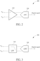
- FIG. 2 is a diagram illustrating an analog front-end circuit 200 according to one embodiment of the present invention, wherein the analog front-end circuit 200 can be used to replace the analog front-end circuit 120 shown in FIG. 1 . As shown in FIG.
- the analog front-end circuit 200 comprises a low-noise amplifier 210 and an ADC 220, wherein the low-noise amplifier 210 is configured to receive input signals V IP and V IN (biopotential signals) from the electrodes 102 and 104 to generate an amplified signal, wherein the input signals V IP and V IN comprises information of the ECG signal and ETI signal; and the ADC 220 performs an analog-to-digital converting operation on the amplified signal to generate a digital signal.
- FIG. 3 is a diagram illustrating an analog front-end circuit 300 according to another embodiment of the present invention, wherein the analog front-end circuit 300 can be used to replace the analog front-end circuit 120 shown in FIG. 1 . As shown in FIG.
- the analog front-end circuit 300 comprises a low-pass filter 310 and an ADC 320, wherein the low-pass filter 310 filters the input signals V IP and V IN (biopotential signals) from the electrodes 102 and 104 to generate a filtered signal, for example, the low-pass filter 310 may filter out components above several kilohertz and retain the components of the ECG signal and ETI signal within the input signals V IP and V IN ; and the ADC 320 performs an analog-to-digital converting operation on the filtered signal to generate a digital signal.
- V IP and V IN biopotential signals
- FIG. 4 is a flowchart of a signal processing method of the biopotential acquisition system 100 according to one embodiment of the present invention. Referring to FIG. 1 and FIG. 4 together, the flowchart of the signal processing method is described as follows.
- Step 400 the flow starts.
- Step 402 generate a transmitter signal for ETI measurement to an input node, wherein the input node is coupled to an electrode of the biopotential acquisition system, and the electrode is used to be in contact with a human body.
- Step 404 use an analog front-end circuit to process an input signal from an input node to generate a digital signal, wherein each of the input signal and the digital signal comprises components of an ECG signal and an ETI signal.
- Step 406 mix the digital signal with mixer data to generate an in-phase mixed signal and a quadrature mixed signal, wherein the mixer data corresponds to a frequency of the transmitter signal, and the in-phase mixed signal and the quadrature mixed signal comprise the components of the ETI signal.
- Step 408 filter the in-phase mixed signal to generate an in-phase ETI signal, filter the quadrature mixed signal to generate a quadrature ETI signal, and filter the digital signal to generate the ECG signal.
- the biopotential acquisition system of the present invention only one analog front-end circuit is used to process two input signals to generate a digital signal comprising the components of the ECG signal and ETI signal, and the mixing operation and the filtering operation for obtaining the ETI signal are performed in digital domain. Therefore, the biopotential acquisition system has smaller chip are and lower power consumption.
Landscapes
- Health & Medical Sciences (AREA)
- Life Sciences & Earth Sciences (AREA)
- Engineering & Computer Science (AREA)
- Animal Behavior & Ethology (AREA)
- Public Health (AREA)
- Pathology (AREA)
- Physics & Mathematics (AREA)
- Biomedical Technology (AREA)
- Heart & Thoracic Surgery (AREA)
- Medical Informatics (AREA)
- Molecular Biology (AREA)
- Surgery (AREA)
- Veterinary Medicine (AREA)
- General Health & Medical Sciences (AREA)
- Biophysics (AREA)
- Cardiology (AREA)
- Signal Processing (AREA)
- Artificial Intelligence (AREA)
- Computer Vision & Pattern Recognition (AREA)
- Physiology (AREA)
- Psychiatry (AREA)
- Dermatology (AREA)
- Nuclear Medicine, Radiotherapy & Molecular Imaging (AREA)
- Radiology & Medical Imaging (AREA)
- Measurement And Recording Of Electrical Phenomena And Electrical Characteristics Of The Living Body (AREA)
- Electrotherapy Devices (AREA)
- Power Engineering (AREA)
Abstract
Description
- This application claims the priority of
US Provisional Application No. 63/075,851 (filed on September 9th, 2020 US Provisional Application No. 63/145,553 (filed on February 4th, 2021 - A conventional medical device generally uses large dry electrodes or wet electrodes to measure physiological signals to obtain physiological features such as bio-impedance or electrocardiography. Recently, personal biosensors such as portable/wearable medical devices become popular for providing physiological information at all time for the reference to the user. Considering the use and design of these portable medical devices, smaller dry electrodes are more appropriate. However, smaller dry electrode means worse electrode impedance, and the worse electrode impedance (i.e. large electrode impedance) may cause detection error of electrocardiography (ECG) signals. In addition, because an electrode-tissue impedance (ETI) may change greatly due to contact factors or motion artifact, it increases the difficulty of measuring ECG signals.
- To solve the problem of the ECG signals in the dry electrode application, the ETI is also detected to reduce the motion artifact in the ECG signals. In the conventional art, a current for the ETI measurement is injected into the electrodes, and an ETI receiver detects the voltages at the electrodes to determine the ETI. In detail, the ETI receiver may comprise a mixer, a low-pass filter and an analog-to-digital converter (ADC), and signals from the electrodes are processed by the mixer, the low-pass filter and the ADC in sequence to generate the ETI information. However, because the ETI receiver is an analog circuit, the ETI receiver has large chip area, higher power consumption and poor mixer harmonics, and the ETI receiver is not friendly to process scaling.
- It is therefore an objective of the present invention to provide a direct sampling ETI system, which uses only one analog front-end circuit to sense the ECG signal and ETI signal simultaneously, to solve the above-mentioned problems.
- According to one embodiment of the present invention, a circuitry of a biopotential acquisition system comprising an input node, an ETI transmitter and an ADC is disclosed. The input node is coupled to an electrode of the biopotential acquisition system, and the electrode is used to be in contact with a human body. The ETI transmitter is configured to generate a transmitter signal to the input node. The ADC is coupled to the input node, and is configured to process an input signal from the input node to generate a digital signal, wherein each of the input signal and the digital signal comprises components of an ECG signal and an ETI signal.
- According to another embodiment of the present invention, a signal processing method of a biopotential acquisition system comprises the steps of: generating a transmitter signal to an input node for an ETI measurement, wherein the input node is coupled to an electrode of the biopotential acquisition system, and the electrode is used to be in contact with a human body; and using an analog front-end circuit to process an input signal from an input node to generate a digital signal, wherein each of the input signal and the digital signal comprises components of an ECG signal and an ETI signal.
- These and other objectives of the present invention will no doubt become obvious to those of ordinary skill in the art after reading the following detailed description of the preferred embodiment that is illustrated in the various figures and drawings.
-
-
FIG. 1 is a diagram illustrating a biopotential acquisition system according to one embodiment of the present invention. -
FIG. 2 is a diagram illustrating an analog front-end circuit according to one embodiment of the present invention. -
FIG. 3 is a diagram illustrating an analog front-end circuit according to another embodiment of the present invention. -
FIG. 4 is a flowchart of a signal processing method of the biopotential acquisition system according to one embodiment of the present invention. - Certain terms are used throughout the following description and claims to refer to particular system components. As one skilled in the art will appreciate, manufacturers may refer to a component by different names. This document does not intend to distinguish between components that differ in name but not function. In the following discussion and in the claims, the terms "including" and "comprising" are used in an open-ended fashion, and thus should be interpreted to mean "including, but not limited to ...". The terms "couple" and "couples" are intended to mean either an indirect or a direct electrical connection. Thus, if a first device couples to a second device, that connection may be through a direct electrical connection, or through an indirect electrical connection via other devices and connections.
-
FIG. 1 is a diagram illustrating abiopotential acquisition system 100 according to one embodiment of the present invention. As shown inFIG. 1 , thebiopotential acquisition system 100 is a two-electrode biopotential acquisition system having twoelectrodes electrodes biopotential acquisition system 100 can process and analyze the biopotential signals to determine physiological signals such as ECG signals, and the physiological features can be displayed on a screen of thebiopotential acquisition system 100. In this embodiment, thebiopotential acquisition system 100 can be built in any portable electronic device or a wearable electronic device. - The
biopotential acquisition system 100 comprises input nodes N1 and N2, an ETI transmitter (in this embodiment, a digital-to-analog converter (DAC) 110 serves as the ETI transmitter), an analog front-end circuit 120, adigital mixer 130 anddigital filters end circuit 120 comprises a low-noise amplifier 122, a low-pass filter 124 and anADC 126; and theDAC 110 can be implemented by any suitable DAC such as a current DAC, a capacitor DAC or a resistor DAC. When theelectrodes biopotential acquisition system 100 may have large input impedance, and the input impedance may change greatly due to contact factors or motion artifact. In the embodiment shown inFIG. 1 , the ETI with the impedance of theelectrode 102/104 are modeled as a resistor REL and a capacitor CEL connected in parallel. In the operation of thebiopotential acquisition system 100, when theelectrodes biopotential acquisition system 100 starts to measure the ECG signals, theDAC 110 receives a digital input signal Din to generate a transmitter signal to theelectrodes end circuit 120 receives the input signals VIP and VIN (biopotential signals) from the input nodes N1 and N2 that are respectively coupled to theelectrodes noise amplifier 122 starts to receive input signals VIP and VIN (biopotential signals) from the input nodes N1 and N2 to generate amplified signals, wherein the input signals VIP and VIN comprise information/components of the ECG signal and ETI signal. Then, the low-pass filter 124 filters the amplified signals to generate filtered signals. In one embodiment, a frequency of the transmitter signal generated by theDAC 110 is higher than the ECG signals, for example, the ECG signals may have frequency lower than several hundred hertz, but the transmitter signal generated by theDAC 110 may be several kilohertz, therefore, the low-pass filter 124 may filter out components above several kilohertz and retain the components of the ECG signal and ETI signal within the amplified signal. Then, the ADC 126 performs an analog-to-digital converting operation on the filtered signal to generate a digital signal. - The
digital mixer 130 has an in-phase path and a quadrature path, and a mixer within the in-phase path mixes an in-phase signal of the digital signal with mixer data whose phase is in-phase with the digital signal to generate an in-phase mixed signal, and a mixer within the quadrature path mixes a quadrature signal of the digital signal with mixer data whose phase is in quadrature with the digital signal to generate a quadrature mixed signal. In this embodiment, a frequency of the mixer data is close to the frequency of the transmitter signal, so that the in-phase mixed signal and the quadrature mixed signal have lower frequency. In addition, thedigital mixer 130 may be a multi-bit digital mixer having good harmonics. - In addition, the phase lead and lag of the signal communication and processing from the
DAC 110 to an input of thedigital mixer 130 can be compensated by internal phase shift compensation at the analog front-end circuit 120 and thedigital mixer 130 to derive practical in-phase mixed signal and quadrature mixed signal. - The
digital filter 140 filters the in-phase mixed signal generated by thedigital mixer 130 to output an in-phase ETI signal ETI_I, and the digital filter 1 50 filters the quadrature mixed signal generated by thedigital mixer 130 to output a quadrature ETI signal ETI_Q. - Meanwhile, because the ECG signals has lower frequency such as several hundred hertz, the
digital filter 160 may directly receive the digital signal outputted by theADC 126, that is the digital signal is not processed by any mixer, and thedigital filter 160 filters out components above several hundred hertz to obtain the ECG signal. - Finally, a following processing circuit (not shown) within the
biopotential acquisition system 100 can notify the user about the motion artifact issue or to adjust/compensate the ECG signal generated by theECG receiver 120 by using the ETI signal. - In the above embodiment, because the ECG signal and the ETI signal are processed by the same analog front-
end circuit 120 simultaneously, and the ECG signal and the ETI signal are converted to digital signal without first performing a mixing operation, thebiopotential acquisition system 100 may have smaller chip area and lower power consumption. In addition, because thedigital mixer 130 is used for the mixing operation of the digital signal, the mixer harmonics can be improved. Furthermore, using thedigital filters biopotential acquisition system 100 can reduce the chip area and reduce data rate. - In the embodiment shown in
FIG. 1 , the analog front-end circuit 120 comprises the low-noise amplifier 122, the low-pass filter 124 and the ADC 126, but this feature is not a limitation of the present invention.FIG. 2 is a diagram illustrating an analog front-end circuit 200 according to one embodiment of the present invention, wherein the analog front-end circuit 200 can be used to replace the analog front-end circuit 120 shown inFIG. 1 . As shown inFIG. 2 , the analog front-end circuit 200 comprises a low-noise amplifier 210 and anADC 220, wherein the low-noise amplifier 210 is configured to receive input signals VIP and VIN (biopotential signals) from theelectrodes ADC 220 performs an analog-to-digital converting operation on the amplified signal to generate a digital signal.FIG. 3 is a diagram illustrating an analog front-end circuit 300 according to another embodiment of the present invention, wherein the analog front-end circuit 300 can be used to replace the analog front-end circuit 120 shown inFIG. 1 . As shown inFIG. 3 , the analog front-end circuit 300 comprises a low-pass filter 310 and anADC 320, wherein the low-pass filter 310 filters the input signals VIP and VIN (biopotential signals) from theelectrodes pass filter 310 may filter out components above several kilohertz and retain the components of the ECG signal and ETI signal within the input signals VIP and VIN; and theADC 320 performs an analog-to-digital converting operation on the filtered signal to generate a digital signal. -
FIG. 4 is a flowchart of a signal processing method of thebiopotential acquisition system 100 according to one embodiment of the present invention. Referring toFIG. 1 andFIG. 4 together, the flowchart of the signal processing method is described as follows. - Step 400: the flow starts.
- Step 402: generate a transmitter signal for ETI measurement to an input node, wherein the input node is coupled to an electrode of the biopotential acquisition system, and the electrode is used to be in contact with a human body.
- Step 404: use an analog front-end circuit to process an input signal from an input node to generate a digital signal, wherein each of the input signal and the digital signal comprises components of an ECG signal and an ETI signal.
- Step 406: mix the digital signal with mixer data to generate an in-phase mixed signal and a quadrature mixed signal, wherein the mixer data corresponds to a frequency of the transmitter signal, and the in-phase mixed signal and the quadrature mixed signal comprise the components of the ETI signal.
- Step 408: filter the in-phase mixed signal to generate an in-phase ETI signal, filter the quadrature mixed signal to generate a quadrature ETI signal, and filter the digital signal to generate the ECG signal.
- Briefly summarized, in the biopotential acquisition system of the present invention, only one analog front-end circuit is used to process two input signals to generate a digital signal comprising the components of the ECG signal and ETI signal, and the mixing operation and the filtering operation for obtaining the ETI signal are performed in digital domain. Therefore, the biopotential acquisition system has smaller chip are and lower power consumption.
- Those skilled in the art will readily observe that numerous modifications and alterations of the device and method may be made while retaining the teachings of the invention. Accordingly, the above disclosure should be construed as limited only by the metes and bounds of the appended claims.
Claims (15)
- A circuitry of a biopotential acquisition system (100), comprising:an input node (N1, N2), wherein the input node (N1, N2) is coupled to an electrode of the biopotential acquisition system (100), and the electrode is use to be in contact with a human body;an electrode-tissue impedance, ETI, transmitter (110), configured to generate a transmitter signal to the input node (N1, N2); andan analog front-end circuit (120, 200, 300), coupled to the input node (N1, N2), configured to process an input signal from the input node (N1, N2) to generate a digital signal, wherein each of the input signal and the digital signal comprises components of an electrocardiography, ECG, signal and an ETI signal.
- The circuitry of claim 1, wherein the analog front-end circuit (120, 200, 300) comprise:an amplifier (122, 210), wherein the amplifier (122, 210) amplifies the input signal to generate an amplified signal;a low-pass filter (124, 310), coupled to the amplifier (122, 210), configured to filters the amplified signal to generate a filtered signal; andan analog-to-digital converter, ADC, coupled to the low-pass filter (124, 310), configured to perform an analog-to-digital converting operation on the filtered signal to generate the digital signal.
- The circuitry of claim 1, wherein the analog front-end circuit (120, 200, 300) comprise:an amplifier (122, 210), wherein the amplifier (122, 210) amplifies the input signal to generate an amplified signal; andan ADC, coupled to the amplifier (122, 210), configured to perform an analog-to-digital converting operation on the amplified signal to generate the digital signal.
- The circuitry of claim 1, wherein the analog front-end circuit (120, 200, 300) comprise:a low-pass filter (124, 310), configured to filter the input signal to generate a filtered signal; andan ADC, coupled to the low-pass filter (124, 310), configured to perform an analog-to-digital converting operation on the filtered signal to generate the digital signal.
- The circuitry of claim 1, further comprising:
a digital filter (140, 150, 160), configured to filter the digital signal to generate the ECG signal. - The circuitry of claim 1, further comprising:
a digital mixer (1 30), configured to mix the digital signal with mixer data to generate an in-phase mixed signal and a quadrature mixed signal, wherein the mixer data corresponds to a frequency of the transmitter signal, and the in-phase mixed signal and the quadrature mixed signal comprise the components of the ETI signal. - The circuitry of claim 6, further comprising:a first digital filter (140), coupled to the digital mixer (130), configured to filter the in-phase mixed signal to generate an in-phase ETI signal; anda second digital filter (1 50), coupled to the digital mixer (130), configured to filter the quadrature mixed signal to generate a quadrature ETI signal.
- The circuitry of claim 7, further comprising:
a third digital filter (160), configured to filter the digital signal to generate the ECG signal. - A signal processing method of a biopotential acquisition system, (100) comprising:generating a transmitter signal to an input node (N1, N2) for an electrode-tissue impedance, ETI, measurement, wherein the input node (N1, N2) is coupled to an electrode of the biopotential acquisition system (100), and the electrode is used to be in contact with a human body; andusing an analog front-end circuit (120, 200, 300)to process an input signal from an input node (N1, N2) to generate a digital signal, wherein each of the input signal and the digital signal comprises components of an electrocardiography, ECG, signal and an ETI signal.
- The signal processing method of claim 9, wherein the step of using the analog front-end circuit (120, 200, 300) to process the input signal from the input node (N1, N2) to generate the digital signal comprises:amplifying the input signal to generate an amplified signal;filtering the amplified signal to generate a filtered signal; andperforming an analog-to-digital converting operation on the filtered signal to generate the digital signal.
- The signal processing method of claim 9, wherein the step of using the analog front-end circuit (120, 200, 300) to process the input signal from the input node (N1, N2) to generate the digital signal comprises:amplifying the input signal to generate an amplified signal; andperforming an analog-to-digital converting operation on the amplified signal to generate the digital signal.
- The signal processing method of claim 9, wherein the step of using the analog front-end circuit (120, 200, 300) to process the input signal from the input node (N1, N2) to generate the digital signal comprises:filtering the input signal to generate a filtered signal; andperforming an analog-to-digital converting operation on the filtered signal to generate the digital signal.
- The signal processing method of claim 9, further comprising:
mixing the digital signal with mixer data to generate an in-phase mixed signal and a quadrature mixed signal, wherein the mixer data corresponds to a frequency of the transmitter signal, and the in-phase mixed signal and the quadrature mixed signal comprise the components of the ETI signal. - The signal processing method of claim 13, further comprising:filtering the in-phase mixed signal to generate an in-phase ETI signal; andfiltering the quadrature mixed signal to generate a quadrature ETI signal.
- The signal processing method of claim 14, further comprising:
filtering the digital signal to generate the ECG signal.
Applications Claiming Priority (3)
| Application Number | Priority Date | Filing Date | Title |
|---|---|---|---|
| US202063075851P | 2020-09-09 | 2020-09-09 | |
| US202163145553P | 2021-02-04 | 2021-02-04 | |
| US17/367,409 US11986306B2 (en) | 2020-09-09 | 2021-07-04 | Direct sampling electrode-tissue impedance system and associated signal processing method |
Publications (2)
| Publication Number | Publication Date |
|---|---|
| EP3967230A1 true EP3967230A1 (en) | 2022-03-16 |
| EP3967230B1 EP3967230B1 (en) | 2025-07-16 |
Family
ID=77226613
Family Applications (1)
| Application Number | Title | Priority Date | Filing Date |
|---|---|---|---|
| EP21189714.5A Active EP3967230B1 (en) | 2020-09-09 | 2021-08-04 | Direct sampling electrode-tissue impedance system and associated signal processing method |
Country Status (4)
| Country | Link |
|---|---|
| US (1) | US11986306B2 (en) |
| EP (1) | EP3967230B1 (en) |
| CN (1) | CN114224312B (en) |
| TW (1) | TWI777725B (en) |
Citations (2)
| Publication number | Priority date | Publication date | Assignee | Title |
|---|---|---|---|---|
| EP2298164A2 (en) * | 2009-09-14 | 2011-03-23 | Imec | Cardiac monitoring circuit with adaptive sampling |
| US20200077955A1 (en) * | 2018-09-11 | 2020-03-12 | Apple Inc. | Contact detection for physiological sensor |
Family Cites Families (9)
| Publication number | Priority date | Publication date | Assignee | Title |
|---|---|---|---|---|
| US7573398B2 (en) * | 2005-06-29 | 2009-08-11 | General Electric Company | System and method of communicating signals |
| EP2294979B1 (en) * | 2009-09-14 | 2013-12-18 | Imec | Method and electronic medical device for simultaneously measuring an impedance and a biopotential signal |
| ITMI20111177A1 (en) * | 2011-06-28 | 2012-12-29 | St Microelectronics Srl | METHOD AND DEVICE FOR MEASURING THE ELECTRICAL IMPEDANCE OF BIOLOGICAL FABRICS |
| US8914099B2 (en) * | 2011-11-08 | 2014-12-16 | Imec | Biomedical acquisition system with motion artifact reduction |
| EP2904963B1 (en) * | 2014-02-06 | 2017-01-25 | IMEC vzw | System and method for acquisition of biopotential signals with motion artifact reduction in real time operation |
| US10517488B2 (en) * | 2016-12-21 | 2019-12-31 | General Electric Company | Patient monitoring system and leadset having multiple capacitive patient connectors and a single galvanic patient connector |
| CN209499724U (en) * | 2018-08-20 | 2019-10-18 | 桂林电子科技大学 | A portable wireless ECG monitoring device |
| US11617531B2 (en) * | 2018-11-23 | 2023-04-04 | Mediatek Inc. | Circuit applied to biopotential acquisition system |
| US11406307B2 (en) * | 2018-12-21 | 2022-08-09 | Biosense Webster (Israel) Ltd. | Impedance measurements using burst pulses to prevent noise on ECG |
-
2021
- 2021-07-04 US US17/367,409 patent/US11986306B2/en active Active
- 2021-08-02 CN CN202110882142.5A patent/CN114224312B/en active Active
- 2021-08-04 EP EP21189714.5A patent/EP3967230B1/en active Active
- 2021-08-12 TW TW110129800A patent/TWI777725B/en active
Patent Citations (2)
| Publication number | Priority date | Publication date | Assignee | Title |
|---|---|---|---|---|
| EP2298164A2 (en) * | 2009-09-14 | 2011-03-23 | Imec | Cardiac monitoring circuit with adaptive sampling |
| US20200077955A1 (en) * | 2018-09-11 | 2020-03-12 | Apple Inc. | Contact detection for physiological sensor |
Non-Patent Citations (1)
| Title |
|---|
| NICK VAN HELLEPUTTE ET AL: "A 160 $\mu{\rm A}$ Biopotential Acquisition IC With Fully Integrated IA and Motion Artifact Suppression", IEEE TRANSACTIONS ON BIOMEDICAL CIRCUITS AND SYSTEMS, IEEE, US, vol. 6, no. 6, 1 December 2012 (2012-12-01), pages 552 - 561, XP011487605, ISSN: 1932-4545, DOI: 10.1109/TBCAS.2012.2224113 * |
Also Published As
| Publication number | Publication date |
|---|---|
| CN114224312B (en) | 2025-08-01 |
| EP3967230B1 (en) | 2025-07-16 |
| TWI777725B (en) | 2022-09-11 |
| TW202210034A (en) | 2022-03-16 |
| CN114224312A (en) | 2022-03-25 |
| US11986306B2 (en) | 2024-05-21 |
| US20220071543A1 (en) | 2022-03-10 |
Similar Documents
| Publication | Publication Date | Title |
|---|---|---|
| EP2294979B1 (en) | Method and electronic medical device for simultaneously measuring an impedance and a biopotential signal | |
| Yazicioglu et al. | A 30$\mu $ w analog signal processor ASIC for portable biopotential signal monitoring | |
| Xu et al. | A $160~\mu {\rm W} $8-Channel Active Electrode System for EEG Monitoring | |
| US8914099B2 (en) | Biomedical acquisition system with motion artifact reduction | |
| US8862210B2 (en) | Analogue signal processors | |
| US8755868B2 (en) | Adaptive sampling | |
| US11096629B2 (en) | Bio-impedance spectroscopy system and method for bio-impedance measurement | |
| US20080159365A1 (en) | Analog Conditioning of Bioelectric Signals | |
| US11617531B2 (en) | Circuit applied to biopotential acquisition system | |
| JPH11188015A (en) | Biological signal measurement device | |
| Mitra et al. | A 700µW 8-channel EEG/contact-impedance acquisition system for dry-electrodes | |
| US11986306B2 (en) | Direct sampling electrode-tissue impedance system and associated signal processing method | |
| US11497411B2 (en) | Circuit applied to bio-information acquisition system | |
| US11937947B2 (en) | Low-noise biopotential acquisition system for dry electrode application | |
| Tanaka et al. | Adaptive noise cancellation method for capacitively coupled ECG sensor using single insulated electrode | |
| TWI752867B (en) | Circuitry of a biopotential acquisition system | |
| US11451366B2 (en) | Lead-on detection circuitry of biopotential acquisition system | |
| CN114305437B (en) | Electrocardiogram feature detection device and method, and electrocardiograph feature detection system | |
| Choi et al. | Advancing electrical impedance spectroscopy (EIS): low-power, high-accuracy, wide-dynamic-range, and high-throughput impedance measurement circuits and architectures | |
| Serrano-Finetti et al. | Compact, Fully-Differential Analog Amplitude Demodulator by Power Supply Voltage Switching | |
| Jiahao et al. | High Precision Portable Bioimpedance Spectrometer for Enhanced Clinical Diagnostics | |
| Shen et al. | Architecture of a mixed-mode electrophysiological signal acquisition interface |
Legal Events
| Date | Code | Title | Description |
|---|---|---|---|
| PUAI | Public reference made under article 153(3) epc to a published international application that has entered the european phase |
Free format text: ORIGINAL CODE: 0009012 |
|
| STAA | Information on the status of an ep patent application or granted ep patent |
Free format text: STATUS: THE APPLICATION HAS BEEN PUBLISHED |
|
| AK | Designated contracting states |
Kind code of ref document: A1 Designated state(s): AL AT BE BG CH CY CZ DE DK EE ES FI FR GB GR HR HU IE IS IT LI LT LU LV MC MK MT NL NO PL PT RO RS SE SI SK SM TR |
|
| STAA | Information on the status of an ep patent application or granted ep patent |
Free format text: STATUS: REQUEST FOR EXAMINATION WAS MADE |
|
| 17P | Request for examination filed |
Effective date: 20220908 |
|
| RBV | Designated contracting states (corrected) |
Designated state(s): AL AT BE BG CH CY CZ DE DK EE ES FI FR GB GR HR HU IE IS IT LI LT LU LV MC MK MT NL NO PL PT RO RS SE SI SK SM TR |
|
| P01 | Opt-out of the competence of the unified patent court (upc) registered |
Effective date: 20230607 |
|
| GRAP | Despatch of communication of intention to grant a patent |
Free format text: ORIGINAL CODE: EPIDOSNIGR1 |
|
| STAA | Information on the status of an ep patent application or granted ep patent |
Free format text: STATUS: GRANT OF PATENT IS INTENDED |
|
| INTG | Intention to grant announced |
Effective date: 20250207 |
|
| GRAS | Grant fee paid |
Free format text: ORIGINAL CODE: EPIDOSNIGR3 |
|
| GRAA | (expected) grant |
Free format text: ORIGINAL CODE: 0009210 |
|
| STAA | Information on the status of an ep patent application or granted ep patent |
Free format text: STATUS: THE PATENT HAS BEEN GRANTED |
|
| AK | Designated contracting states |
Kind code of ref document: B1 Designated state(s): AL AT BE BG CH CY CZ DE DK EE ES FI FR GB GR HR HU IE IS IT LI LT LU LV MC MK MT NL NO PL PT RO RS SE SI SK SM TR |
|
| REG | Reference to a national code |
Ref country code: GB Ref legal event code: FG4D |
|
| REG | Reference to a national code |
Ref country code: CH Ref legal event code: EP |
|
| REG | Reference to a national code |
Ref country code: DE Ref legal event code: R096 Ref document number: 602021034081 Country of ref document: DE |
|
| REG | Reference to a national code |
Ref country code: IE Ref legal event code: FG4D |
|
| PGFP | Annual fee paid to national office [announced via postgrant information from national office to epo] |
Ref country code: DE Payment date: 20250714 Year of fee payment: 5 |
|
| PGFP | Annual fee paid to national office [announced via postgrant information from national office to epo] |
Ref country code: GB Payment date: 20250718 Year of fee payment: 5 |
|
| PGFP | Annual fee paid to national office [announced via postgrant information from national office to epo] |
Ref country code: FR Payment date: 20250730 Year of fee payment: 5 Ref country code: AT Payment date: 20251020 Year of fee payment: 5 |
|
| REG | Reference to a national code |
Ref country code: NL Ref legal event code: MP Effective date: 20250716 |
|
| PG25 | Lapsed in a contracting state [announced via postgrant information from national office to epo] |
Ref country code: PT Free format text: LAPSE BECAUSE OF FAILURE TO SUBMIT A TRANSLATION OF THE DESCRIPTION OR TO PAY THE FEE WITHIN THE PRESCRIBED TIME-LIMIT Effective date: 20251117 |
|
| PG25 | Lapsed in a contracting state [announced via postgrant information from national office to epo] |
Ref country code: NL Free format text: LAPSE BECAUSE OF FAILURE TO SUBMIT A TRANSLATION OF THE DESCRIPTION OR TO PAY THE FEE WITHIN THE PRESCRIBED TIME-LIMIT Effective date: 20250716 |
|
| REG | Reference to a national code |
Ref country code: AT Ref legal event code: MK05 Ref document number: 1813283 Country of ref document: AT Kind code of ref document: T Effective date: 20250716 |
|
| PG25 | Lapsed in a contracting state [announced via postgrant information from national office to epo] |
Ref country code: IS Free format text: LAPSE BECAUSE OF FAILURE TO SUBMIT A TRANSLATION OF THE DESCRIPTION OR TO PAY THE FEE WITHIN THE PRESCRIBED TIME-LIMIT Effective date: 20251116 |
|
| PG25 | Lapsed in a contracting state [announced via postgrant information from national office to epo] |
Ref country code: NO Free format text: LAPSE BECAUSE OF FAILURE TO SUBMIT A TRANSLATION OF THE DESCRIPTION OR TO PAY THE FEE WITHIN THE PRESCRIBED TIME-LIMIT Effective date: 20251016 |
|
| REG | Reference to a national code |
Ref country code: LT Ref legal event code: MG9D |
|
| PG25 | Lapsed in a contracting state [announced via postgrant information from national office to epo] |
Ref country code: AT Free format text: LAPSE BECAUSE OF FAILURE TO SUBMIT A TRANSLATION OF THE DESCRIPTION OR TO PAY THE FEE WITHIN THE PRESCRIBED TIME-LIMIT Effective date: 20250716 |
|
| PG25 | Lapsed in a contracting state [announced via postgrant information from national office to epo] |
Ref country code: FI Free format text: LAPSE BECAUSE OF FAILURE TO SUBMIT A TRANSLATION OF THE DESCRIPTION OR TO PAY THE FEE WITHIN THE PRESCRIBED TIME-LIMIT Effective date: 20250716 |
|
| PG25 | Lapsed in a contracting state [announced via postgrant information from national office to epo] |
Ref country code: HR Free format text: LAPSE BECAUSE OF FAILURE TO SUBMIT A TRANSLATION OF THE DESCRIPTION OR TO PAY THE FEE WITHIN THE PRESCRIBED TIME-LIMIT Effective date: 20250716 |
|
| PG25 | Lapsed in a contracting state [announced via postgrant information from national office to epo] |
Ref country code: GR Free format text: LAPSE BECAUSE OF FAILURE TO SUBMIT A TRANSLATION OF THE DESCRIPTION OR TO PAY THE FEE WITHIN THE PRESCRIBED TIME-LIMIT Effective date: 20251017 |
|
| PG25 | Lapsed in a contracting state [announced via postgrant information from national office to epo] |
Ref country code: SE Free format text: LAPSE BECAUSE OF FAILURE TO SUBMIT A TRANSLATION OF THE DESCRIPTION OR TO PAY THE FEE WITHIN THE PRESCRIBED TIME-LIMIT Effective date: 20250716 |
|
| PG25 | Lapsed in a contracting state [announced via postgrant information from national office to epo] |
Ref country code: LV Free format text: LAPSE BECAUSE OF FAILURE TO SUBMIT A TRANSLATION OF THE DESCRIPTION OR TO PAY THE FEE WITHIN THE PRESCRIBED TIME-LIMIT Effective date: 20250716 |
|
| PG25 | Lapsed in a contracting state [announced via postgrant information from national office to epo] |
Ref country code: BG Free format text: LAPSE BECAUSE OF FAILURE TO SUBMIT A TRANSLATION OF THE DESCRIPTION OR TO PAY THE FEE WITHIN THE PRESCRIBED TIME-LIMIT Effective date: 20250716 Ref country code: PL Free format text: LAPSE BECAUSE OF FAILURE TO SUBMIT A TRANSLATION OF THE DESCRIPTION OR TO PAY THE FEE WITHIN THE PRESCRIBED TIME-LIMIT Effective date: 20250716 |
|
| PG25 | Lapsed in a contracting state [announced via postgrant information from national office to epo] |
Ref country code: RS Free format text: LAPSE BECAUSE OF FAILURE TO SUBMIT A TRANSLATION OF THE DESCRIPTION OR TO PAY THE FEE WITHIN THE PRESCRIBED TIME-LIMIT Effective date: 20251016 |
|
| PG25 | Lapsed in a contracting state [announced via postgrant information from national office to epo] |
Ref country code: ES Free format text: LAPSE BECAUSE OF FAILURE TO SUBMIT A TRANSLATION OF THE DESCRIPTION OR TO PAY THE FEE WITHIN THE PRESCRIBED TIME-LIMIT Effective date: 20250716 |
|
| PG25 | Lapsed in a contracting state [announced via postgrant information from national office to epo] |
Ref country code: RO Free format text: LAPSE BECAUSE OF FAILURE TO SUBMIT A TRANSLATION OF THE DESCRIPTION OR TO PAY THE FEE WITHIN THE PRESCRIBED TIME-LIMIT Effective date: 20250716 |
|
| REG | Reference to a national code |
Ref country code: CH Ref legal event code: H13 Free format text: ST27 STATUS EVENT CODE: U-0-0-H10-H13 (AS PROVIDED BY THE NATIONAL OFFICE) Effective date: 20260324 |
|
| PG25 | Lapsed in a contracting state [announced via postgrant information from national office to epo] |
Ref country code: SM Free format text: LAPSE BECAUSE OF FAILURE TO SUBMIT A TRANSLATION OF THE DESCRIPTION OR TO PAY THE FEE WITHIN THE PRESCRIBED TIME-LIMIT Effective date: 20250716 |
|
| PG25 | Lapsed in a contracting state [announced via postgrant information from national office to epo] |
Ref country code: DK Free format text: LAPSE BECAUSE OF FAILURE TO SUBMIT A TRANSLATION OF THE DESCRIPTION OR TO PAY THE FEE WITHIN THE PRESCRIBED TIME-LIMIT Effective date: 20250716 |
|
| PG25 | Lapsed in a contracting state [announced via postgrant information from national office to epo] |
Ref country code: LU Free format text: LAPSE BECAUSE OF NON-PAYMENT OF DUE FEES Effective date: 20250804 Ref country code: IT Free format text: LAPSE BECAUSE OF FAILURE TO SUBMIT A TRANSLATION OF THE DESCRIPTION OR TO PAY THE FEE WITHIN THE PRESCRIBED TIME-LIMIT Effective date: 20250716 |
|
| PG25 | Lapsed in a contracting state [announced via postgrant information from national office to epo] |
Ref country code: CH Free format text: LAPSE BECAUSE OF NON-PAYMENT OF DUE FEES Effective date: 20250831 Ref country code: CZ Free format text: LAPSE BECAUSE OF FAILURE TO SUBMIT A TRANSLATION OF THE DESCRIPTION OR TO PAY THE FEE WITHIN THE PRESCRIBED TIME-LIMIT Effective date: 20250716 |
|
| PG25 | Lapsed in a contracting state [announced via postgrant information from national office to epo] |
Ref country code: SK Free format text: LAPSE BECAUSE OF FAILURE TO SUBMIT A TRANSLATION OF THE DESCRIPTION OR TO PAY THE FEE WITHIN THE PRESCRIBED TIME-LIMIT Effective date: 20250716 Ref country code: EE Free format text: LAPSE BECAUSE OF FAILURE TO SUBMIT A TRANSLATION OF THE DESCRIPTION OR TO PAY THE FEE WITHIN THE PRESCRIBED TIME-LIMIT Effective date: 20250716 |