EP3966596B1 - Phasendifferenzdetektionssystem und verfahren zum erkennen einer phasendifferenz - Google Patents
Phasendifferenzdetektionssystem und verfahren zum erkennen einer phasendifferenz Download PDFInfo
- Publication number
- EP3966596B1 EP3966596B1 EP20721653.2A EP20721653A EP3966596B1 EP 3966596 B1 EP3966596 B1 EP 3966596B1 EP 20721653 A EP20721653 A EP 20721653A EP 3966596 B1 EP3966596 B1 EP 3966596B1
- Authority
- EP
- European Patent Office
- Prior art keywords
- phase difference
- detection system
- grating
- target location
- grating coupler
- Prior art date
- Legal status (The legal status is an assumption and is not a legal conclusion. Google has not performed a legal analysis and makes no representation as to the accuracy of the status listed.)
- Active
Links
Images



Classifications
-
- G—PHYSICS
- G01—MEASURING; TESTING
- G01S—RADIO DIRECTION-FINDING; RADIO NAVIGATION; DETERMINING DISTANCE OR VELOCITY BY USE OF RADIO WAVES; LOCATING OR PRESENCE-DETECTING BY USE OF THE REFLECTION OR RERADIATION OF RADIO WAVES; ANALOGOUS ARRANGEMENTS USING OTHER WAVES
- G01S17/00—Systems using the reflection or reradiation of electromagnetic waves other than radio waves, e.g. lidar systems
- G01S17/02—Systems using the reflection of electromagnetic waves other than radio waves
-
- G—PHYSICS
- G01—MEASURING; TESTING
- G01S—RADIO DIRECTION-FINDING; RADIO NAVIGATION; DETERMINING DISTANCE OR VELOCITY BY USE OF RADIO WAVES; LOCATING OR PRESENCE-DETECTING BY USE OF THE REFLECTION OR RERADIATION OF RADIO WAVES; ANALOGOUS ARRANGEMENTS USING OTHER WAVES
- G01S17/00—Systems using the reflection or reradiation of electromagnetic waves other than radio waves, e.g. lidar systems
- G01S17/02—Systems using the reflection of electromagnetic waves other than radio waves
- G01S17/50—Systems of measurement based on relative movement of target
- G01S17/58—Velocity or trajectory determination systems; Sense-of-movement determination systems
-
- G—PHYSICS
- G01—MEASURING; TESTING
- G01S—RADIO DIRECTION-FINDING; RADIO NAVIGATION; DETERMINING DISTANCE OR VELOCITY BY USE OF RADIO WAVES; LOCATING OR PRESENCE-DETECTING BY USE OF THE REFLECTION OR RERADIATION OF RADIO WAVES; ANALOGOUS ARRANGEMENTS USING OTHER WAVES
- G01S7/00—Details of systems according to groups G01S13/00, G01S15/00, G01S17/00
- G01S7/48—Details of systems according to groups G01S13/00, G01S15/00, G01S17/00 of systems according to group G01S17/00
- G01S7/481—Constructional features, e.g. arrangements of optical elements
-
- G—PHYSICS
- G01—MEASURING; TESTING
- G01S—RADIO DIRECTION-FINDING; RADIO NAVIGATION; DETERMINING DISTANCE OR VELOCITY BY USE OF RADIO WAVES; LOCATING OR PRESENCE-DETECTING BY USE OF THE REFLECTION OR RERADIATION OF RADIO WAVES; ANALOGOUS ARRANGEMENTS USING OTHER WAVES
- G01S7/00—Details of systems according to groups G01S13/00, G01S15/00, G01S17/00
- G01S7/48—Details of systems according to groups G01S13/00, G01S15/00, G01S17/00 of systems according to group G01S17/00
- G01S7/481—Constructional features, e.g. arrangements of optical elements
- G01S7/4811—Constructional features, e.g. arrangements of optical elements common to transmitter and receiver
- G01S7/4812—Constructional features, e.g. arrangements of optical elements common to transmitter and receiver transmitted and received beams following a coaxial path
-
- G—PHYSICS
- G01—MEASURING; TESTING
- G01S—RADIO DIRECTION-FINDING; RADIO NAVIGATION; DETERMINING DISTANCE OR VELOCITY BY USE OF RADIO WAVES; LOCATING OR PRESENCE-DETECTING BY USE OF THE REFLECTION OR RERADIATION OF RADIO WAVES; ANALOGOUS ARRANGEMENTS USING OTHER WAVES
- G01S7/00—Details of systems according to groups G01S13/00, G01S15/00, G01S17/00
- G01S7/48—Details of systems according to groups G01S13/00, G01S15/00, G01S17/00 of systems according to group G01S17/00
- G01S7/481—Constructional features, e.g. arrangements of optical elements
- G01S7/4818—Constructional features, e.g. arrangements of optical elements using optical fibres
-
- G—PHYSICS
- G01—MEASURING; TESTING
- G01S—RADIO DIRECTION-FINDING; RADIO NAVIGATION; DETERMINING DISTANCE OR VELOCITY BY USE OF RADIO WAVES; LOCATING OR PRESENCE-DETECTING BY USE OF THE REFLECTION OR RERADIATION OF RADIO WAVES; ANALOGOUS ARRANGEMENTS USING OTHER WAVES
- G01S7/00—Details of systems according to groups G01S13/00, G01S15/00, G01S17/00
- G01S7/48—Details of systems according to groups G01S13/00, G01S15/00, G01S17/00 of systems according to group G01S17/00
- G01S7/491—Details of non-pulse systems
- G01S7/4912—Receivers
- G01S7/4915—Time delay measurement, e.g. operational details for pixel components; Phase measurement
-
- G—PHYSICS
- G01—MEASURING; TESTING
- G01B—MEASURING LENGTH, THICKNESS OR SIMILAR LINEAR DIMENSIONS; MEASURING ANGLES; MEASURING AREAS; MEASURING IRREGULARITIES OF SURFACES OR CONTOURS
- G01B5/00—Measuring arrangements characterised by the use of mechanical techniques
- G01B5/02—Measuring arrangements characterised by the use of mechanical techniques for measuring length, width or thickness
Definitions
- the present disclosure relates to a phase difference detection system for a single target location.
- the present disclosure further relates to a method for detecting a phase difference between two laser beams due to reflection at a target location.
- Phase difference detectors are used in different areas of technology, including laser Doppler vibrometry and determining refractive index changes at different locations of a medium.
- a laser Doppler vibrometer (LDV) 1 is an instrument used to measure the temporal velocity or displacement of a vibrating surface 2 as illustrated in Figure 1 .
- the LDV 1 sends out a laser beam 3 which is reflected by surface 2 located a distance d 0 away.
- the incoming reflected laser beam 4 is received by the LDV 1.
- the instantaneous frequency shift of the reflection signal f Doppler ( t ) is proportional to the temporal velocity v(t) of the target surface.
- ⁇ Doppler t 2 ⁇ ⁇ 0 ⁇ 2 ⁇ d t .
- ⁇ d ( t ) is the displacement of the target surface in the direction of the laser beam.
- a factor of 2 is placed before ⁇ d ( t ) because the optical path change of the beam corresponds to a roundtrip of the displacement.
- Laser Doppler vibrometry shows great vibration measurement accuracy with sub-nanometer resolution and has been applied in various fields, e.g. in bio-medical engineering and mechanics.
- Scanning LDV systems are used more often thanks to their flexibility and simplicity compared to the multi-beam LDV systems.
- the performance of the scanning LDV is limited by its scanning frequency, which usually cannot reach the MHz range due to mechanics-based scanning devices. Therefore, scanning LDV systems cannot typically detect a transient movement event, such as an impact.
- a multi-beam LDV system has no such limitations and it can measure transient and non-periodic events.
- a multi-beam LDV system is usually more bulky and complex.
- Another two splitters are used to split the reference beam and the measurement beam into six individual reference beams and measurement beams.
- Each of the six phase difference detectors has the same, common, design.
- the individual measurement beams are sent towards the target by a transmit antenna and the reflection is received.
- the received reflected signal is sent to a mixer, e.g. a 90° optical hybrid, that mixes the received reflected signal and the reference signal.
- a mixer e.g. a 90° optical hybrid
- the mixer has four optical output signals that are converted, by photo-diodes, into photo-current signals.
- Using a demodulator allows determining the desired movement information from the photo-current signals.
- While such a PIC may accommodate six LDVs, it is not easy to integrate a larger number of LDVs, e.g. more than twenty, on a single chip with a limited footprint, e.g. 1 mm 2 . Especially the bonding pads and waveguide routes limit the number of LDVs realized on a single chip.
- WO 2018/015517 A1 discloses a lens free imaging device for creating holographic images.
- the lens free imaging device comprises a waveguide with a first diffracting element to split a part of the waveguide light into a first light wave oriented to a target and a second light wave oriented towards an image sensor.
- the first light wave is scattered by the target and the resulting scattered light wave is also received at the image sensor.
- the scattered light wave and the second light wave are combined to form an image.
- phase difference detection system for a single target location
- the phase difference detection system comprising: a laser source to generate a laser beam; a phase difference detector coupled to the laser source and having a multi-layer structure comprising: a planar waveguide for guiding the laser beam, the planar waveguide having a normal direction and forming a first layer of the multi-layer structure; a grating coupler to split the laser beam into a reference beam and a measurement beam, wherein the measurement beam is directed towards the target location and the reference beam is directed away from the target location, the reference beam and the measurement beam each being inclined with respect to said normal direction; and a planar imager array forming a second layer of the multi-layer structure, the imager array being configured to detect a fringe pattern generated by said reference beam and an incoming beam, the incoming beam being the result of the measurement beam having been reflected at the target location and having passed through the grating coupler; and an external optical system configured to focus the measurement beam output from the phase difference detector on the
- the grating coupler couples the coherent light from the waveguide to both upward and downward directions of the grating coupler, i.e. it splits the coherent light from the waveguide into the reference beam and the measurement beam.
- the wavelength of the laser beam, the refractive index of the grating coupler and the period of the grating coupler are so chosen such as to ensure that the reference beam and the measurement beam each are inclined with respect to the normal direction of the waveguide. This is possible as these quantities are linked as discussed below.
- the measurement laser beam is focused to the target location with the help of an optical system. Due to reflection at the target location, a reflected beam is sent back towards the phase difference detector, i.e. towards the grating coupler.
- the reflected beam can be considered to be parallel to the measurement beam but travelling in the opposite direction.
- the incoming beam that is the result of the measurement beam having been reflected at the target location and the reference beam are angled with respect to one another so they create an interference pattern, also known as a fringe pattern.
- the imager array detects this fringe pattern from which the phase difference between the reference beam and the incoming beam may be determined.
- the grating coupler affects light passing through it, the phase behaviour of the incoming beam which passes through the grating coupler remains unaffected. As such, the fringe pattern is not affected by the incoming beam passing through the grating coupler.
- the optical system comprises a small aperture, in particular a pin-hole, provided above the grating coupler.
- the small aperture corrects this and ensures that the reflected beam, after having passed the small aperture, is parallel to the outgoing beam.
- the first layer and the second layer are separated by a distance of 1 ⁇ m to 20 ⁇ m.
- the reference beam and the measurement beam each are inclined with respect to said normal direction with an angle that is between 1° and 10°, which angle is preferably 2°.
- said grating coupler is one of: a slanted grating, a curved grating, a compact grating, a patterned grating, an apodized grating, a 2D grating and a 2D apodized grating.
- the grating coupler is formed by one of: grooves in the waveguide, which grooves may optionally be filled with a material different from the waveguide material, or protrusions from the waveguide, which protrusions may optionally be formed from a material different from the waveguide material.
- the grating coupler comprises at least one additional layer separated from the waveguide.
- said imager array comprises a plurality of CCD, CMOS or NMOS imagers.
- the various possible designs of the imager array allow flexibility in designing the phase difference detector.
- the phase difference detector further comprises a processing unit configured to determine a phase shift between the reference beam and the incoming beam based on the fringe pattern.
- the phase difference detector is used to perform laser Doppler vibrometry of the target location.
- the object according to the present disclosure is also obtained by a method for detecting a phase difference between two laser beams due to reflection at a target location using the phase difference detector described above, the method comprising the steps of: guiding a laser beam within the planar waveguide having a normal direction; splitting the laser beam by means of the grating coupler into a reference beam and a measurement beam, wherein the measurement beam is directed towards the target location and the reference beam is directed away from the target location, the reference beam and the measurement beam each being inclined with respect to said normal direction; detecting a fringe pattern generated by said reference beam and an incoming beam, the incoming beam being the result of the measurement beam having been reflected at the target location and having passed through the grating coupler; and deriving a phase difference between the reference beam and the incoming beam based on the fringe pattern.
- phase difference detector according to the present disclosure will be explained by reference to its use in laser Doppler vibrometry.
- the phase difference detector according to the present disclosure may also be used with a static reflector which induces no phase changes in the reflected light.
- a static reflector which induces no phase changes in the reflected light.
- the distribution of pressure or temperature may be derived, which, in turn, may be used to map changes in sound speed.
- Another possible application is the movement (e.g. tilt or rotation) of an entire surface which may be derived from the phase change at each location.
- the phase shifts at various locations across the surface will be related to one another due to the rotational movement, which relation allows to detect the movement.
- a phase difference detector 10 according to the present disclosure is shown in Figure 2 .
- the phase difference detector 10 comprises an incoming waveguide 12 attached to a grating coupler 14.
- the incoming waveguide 12 is connected to an external laser source (not shown) either in a direct connection or through the intermediary of one or more other waveguides and/or splitters.
- the laser beam guided in the incoming waveguide 12 passes the grating coupler 14 as indicated by arrow 22, which causes the laser beam to be split into at least two components, namely an upwards travelling measurement beam 16 and a downwards travelling reference beam 18.
- a part of the laser beam may also continue onwards past the grating coupler 14 to remain in an outgoing waveguide 20 that may be coupled to a subsequent phase difference detector as described in greater detail with respect to Figure 6 .
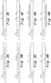
- Figures 3A and 3B illustrate a waveguide-grating coupler pair 12, 14 that is formed by removing part of the material of the waveguide 12 to form a crenelated surface which acts as the grating coupler 14.
- the crenelated surface may be either the top surface ( Figure 3A ) or the bottom surface ( Figure 3B ) of the waveguide 12.
- Figures 3C and 3D A similar design is shown in Figures 3C and 3D where, instead of removing material, material has been added to form the crenelated surface.
- the waveguide-grating coupler pair 12, 14 of Figures 3E and 3F has the same shape as those of Figures 3C and 3D , but the material that was added on top of or below the waveguide 12 to act as the grating coupler 14 is different to the material of the waveguide 12.
- the waveguide may be silicon nitride, while the material surrounding silicon nitride can be silicon oxide, air or other materials with a low refractive index.
- the grating coupler 14 may also not be in direct contact with the waveguide 12 as shown in Figure 3G and 3H .
- the grating coupler 14 may be formed by various layers as illustrated in Figures 3I and 3J .
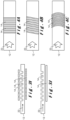
- crenelated surface that acts as the grating coupler 14 may also have different planar configurations as shown in the top views of Figures 4A to 4I .
- Figures 4A to 4C illustrate a perpendicular, slanted and curved waveguide-grating coupler pair 12, 14 respectively.
- a compact grating coupler 14 as illustrated in Figures 4D and 4E .
- a patterned grating coupler 14 is illustrated in Figure 4F
- an apodized grating coupler 14 is shown in Figure 4G .
- Two-dimensional grating couplers 14 are also possible as shown in Figures 4H and 4I .
- the grating coupler 14 should split the light upward and downward with a proper splitting ratio. Typically, more light should be sent to the measurement target, so that the interference pattern has a good signal quality. Another important factor is that the grating coupler 14 should be long enough to cover more than 2 fringes, but not too long to avoid distributing the optical power to a too large region. A third important factor is that most light is preferably coupled to upward or downward directions rather than being reflected or transmitted through the grating.
- the upwards travelling measurement beam 16 is focussed on a single target location 24 by use of an external optical focussing system 26, e.g. one or more lenses. Due to reflection at the target location, a reflected beam is sent back towards the phase difference detector 10, again via the external optical focussing system 26.
- the optical system 26 preferably includes a small aperture, such as a pin-hole, which ensures that the reflected laser beam is parallel to the measurement beam 16 but travelling in the opposite direction when arriving back at the phase detector 10, in particular the grating coupler 14 thereof.
- the incoming beam 28 that is the result of the measurement beam 16 having been reflected at the target location 24 and the reference beam 18 are angled with respect to one another. This angle is illustrated by means of lines 30, 32 that illustrate the wave front of the reference beam 18 and the incoming beam 28 respectively.
- an interference pattern 34 also known as a fringe pattern.
- the phase difference detector 10 is provided with an imager array 36 that detects this fringe pattern from which the phase difference between the reference beam 18 and the incoming beam 28 may be determined.
- the phase difference of the incoming beam 28 can be determined by viewing the phase shift of the fringe pattern.
- various techniques may be used on the data obtained from the imager array 36. Examples of such techniques are a fast-Fourier transform, cross-correlation, and other methods.
- imager arrays 36 may be used.
- a plurality of CCD, CMOS or NMOS imagers may be used.
- the preference for one type of imager of the other depends on the sensitivity (the higher the better), the pixel size (the smaller the better), the frame rate (the higher the better) and the cost.
- the distance d between the waveguide-grating coupler layer 12, 14 and the imager array 36 is dependent on the application.
- the maximal distance d determines the size of the interference pattern.
- the angle ⁇ determines the period of fringe, which is ⁇ 2 sin ⁇ .
- the pitch of the imager array 36 is smaller than 1 ⁇ 4 of the fringes to ensure a good resolution.
- the pixel pitch is smaller than 1 4 ⁇ 2 sin ⁇ .
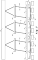
- Figures 5 to 7 show various phase detector designs for simultaneous phase change detection at different locations. It should be noted that reference number 26 is used to denote any kind of appropriate external optical focussing system, which may include one or more convex or concave lenses.
- Figure 5 illustrates a chip 100 having two phase difference detectors that share a common imager array 36.
- the waveguides 12 are split from one another and may be connected to a same external laser source (not shown), e.g. via splitter, or to different external laser sources. Due to the presence of two grating couplers 14, a simultaneous measurement at two different locations is possible.
- Figure 6 shows a slight variation of the design of Figure 5 where the waveguides 12 are connected to one another.
- Figure 7 Another possible design is shown in Figure 7 where multiple external focussing systems 26 are provided to focus the output of an elongated grating coupler 14 to various locations on the target 24.
- phase difference detectors may also be set-up in a two-dimensional array structure.
Landscapes
- Engineering & Computer Science (AREA)
- Physics & Mathematics (AREA)
- Computer Networks & Wireless Communication (AREA)
- General Physics & Mathematics (AREA)
- Radar, Positioning & Navigation (AREA)
- Remote Sensing (AREA)
- Electromagnetism (AREA)
- Length Measuring Devices By Optical Means (AREA)
Claims (11)
- Ein Phasendifferenzdetektionssystem für einen Einzelzielstandort (24), wobei das Phasendifferenzdetektionssystem Folgendes umfasst:- eine Laserquelle, um einen Laserstrahl zu erzeugen;- einen Phasendifferenzdetektor (10), gekoppelt an die Laserquelle und versehen mit einer mehrschichtigen Struktur, welche Folgendes umfasst:- einen planaren Wellenleiter (12) zum Führen des Laserstrahls, wobei der planare Wellenleiter eine Normalrichtung (N) hat und eine erste Schicht der mehrschichtigen Struktur bildet;- einen Gitterkoppler (14), um den Laserstrahl in einen Referenzstrahl (18) und einen Messstrahl (16) aufzuteilen, wobei der Messstrahl auf den Zielstandort gerichtet ist und der Referenzstrahl vom Zielstandort weg gerichtet ist, wobei der Referenzstrahl und der Messstrahl jeweils in Bezug auf die erwähnte Normalrichtung geneigt sind; und- eine planare Imager-Anordnung (36), welche eine zweite Schicht der mehrschichtigen Struktur bildet, wobei die planare Imager-Anordnung unter dem Gitterkoppler angeordnet ist, was die erforderliche Fläche auf dem Chip reduziert, wobei die planare Imager-Anordnung konfiguriert ist, um ein Streifenmuster zu erkennen, das durch den erwähnten Referenzstrahl und einen eingehenden Strahl erzeugt wird, wobei der eingehende Strahl das Ergebnis dessen ist, dass der Messstrahl am Zielstandort reflektiert wurde und den Gitterkoppler durchquert hat, undein externes optisches System (26), konfiguriert, um den Messstrahl-Output vom Phasendifferenzdetektor auf den Einzelzielstandort zu fokussieren und um am Zielstandort reflektierte Signale auf den Phasendifferenzdetektor zu fokussieren.
- Phasendifferenzdetektionssystem nach Anspruch 1, wobei das optische System eine kleine Öffnung, insbesondere ein Nadelloch, umfasst, bereitgestellt über dem Gitterkoppler.
- Phasendifferenzdetektionssystem nach Anspruch 1 oder 2, wobei die erste Schicht und die zweite Schicht durch einen Abstand von 1 µm bis 20 µm getrennt sind.
- Phasendifferenzdetektionssystem nach irgendeinem der vorigen Ansprüche, wobei der Referenzstrahl und der Messstrahl jeweils in Bezug auf die erwähnte Normalrichtung um einen Winkel geneigt sind, der zwischen 1° und 10° beträgt, wobei der Winkel bevorzugt 2° beträgt.
- Phasendifferenzdetektionssystem nach irgendeinem der vorigen Ansprüche, wobei der erwähnte Gitterkoppler eines der folgenden Elemente ist: ein schräges Gitter, ein gebogenes Gitter, ein kompaktes Gitter, ein strukturiertes Gitter, ein apodisiertes Gitter, ein 2D-Gitter und ein apodisiertes 2D-Gitter.
- Phasendifferenzdetektionssystem nach irgendeinem der vorigen Ansprüche, wobei der Gitterkoppler durch eines der folgenden Elemente gebildet ist: Nuten im Wellenleiter, wobei diese Nuten optional mit einem anderen Material als dem Wellenleitermaterial gefüllt sein können, oder Vorsprünge vom Wellenleiter, wobei diese Vorsprünge optional aus einem anderen Material als dem Wellenleitermaterial gebildet sein können.
- Phasendifferenzdetektionssystem nach irgendeinem der vorigen Ansprüche, wobei der Gitterkoppler mindestens eine zusätzliche Schicht getrennt vom Wellenleiter umfasst.
- Phasendifferenzdetektionssystem nach irgendeinem der vorigen Ansprüche, wobei die erwähnte Imager-Anordnung eine Vielzahl von CCD-, CMOS- oder NMOS-Imagern umfasst.
- Phasendifferenzdetektionssystem nach irgendeinem der vorigen Ansprüche, wobei der Phasendifferenzdetektor ferner eine Verarbeitungseinheit umfasst, konfiguriert, um eine Phasenverschiebung zwischen dem Referenzstrahl und dem eingehenden Strahl basierend auf dem Streifenmuster zu bestimmen.
- Verwendung des Phasendifferenzdetektionssystem nach irgendeinem der vorigen Ansprüche, um Laser-Doppler-Vibrometrie des Zielstandorts durchzuführen.
- Verfahren zur Erkennung eines Phasenunterschieds zwischen zwei Laserstrahlen aufgrund von Reflexion an einem Zielstandort (24) unter Verwendung des Phasendifferenzdetektionssystems nach irgendeinem der Ansprüche 1 bis 9, wobei das Verfahren die folgenden Schritte umfasst:- Führen eines Laserstrahls innerhalb des planaren Wellenleiters (12), der eine Normalrichtung hat;- Aufteilen des Laserstrahls mittels des Gitterkopplers in einen Referenzstrahl (18) und einen Messstrahl (16), wobei der Messstrahl auf den Zielstandort gerichtet ist und der Referenzstrahl vom Zielstandort weg gerichtet ist, wobei der Referenzstrahl und der Messstrahl jeweils in Bezug auf die erwähnte Normalrichtung geneigt sind;- Erkennen eines Streifenmusters durch die planare Imager-Anordnung, welches durch den erwähnten Referenzstrahl und einen eingehenden Strahl erzeugt ist, wobei der eingehende Strahl das Ergebnis dessen ist, dass der Messstrahl am Zielstandort reflektiert wurde und den Gitterkoppler durchquert hat; und- Ableiten eines Phasenunterschieds zwischen dem Referenzstrahl und dem eingehenden Strahl basierend auf dem Streifenmuster.
Applications Claiming Priority (2)
| Application Number | Priority Date | Filing Date | Title |
|---|---|---|---|
| EP19173535.6A EP3736606A1 (de) | 2019-05-09 | 2019-05-09 | Phasendifferenzdetektor, chip damit, phasendifferenzdetektionssystem und verfahren zum erkennen einer phasendifferenz |
| PCT/EP2020/062265 WO2020225187A1 (en) | 2019-05-09 | 2020-05-04 | A phase difference detection system and a method for detecting a phase difference |
Publications (2)
| Publication Number | Publication Date |
|---|---|
| EP3966596A1 EP3966596A1 (de) | 2022-03-16 |
| EP3966596B1 true EP3966596B1 (de) | 2025-06-25 |
Family
ID=66476503
Family Applications (2)
| Application Number | Title | Priority Date | Filing Date |
|---|---|---|---|
| EP19173535.6A Withdrawn EP3736606A1 (de) | 2019-05-09 | 2019-05-09 | Phasendifferenzdetektor, chip damit, phasendifferenzdetektionssystem und verfahren zum erkennen einer phasendifferenz |
| EP20721653.2A Active EP3966596B1 (de) | 2019-05-09 | 2020-05-04 | Phasendifferenzdetektionssystem und verfahren zum erkennen einer phasendifferenz |
Family Applications Before (1)
| Application Number | Title | Priority Date | Filing Date |
|---|---|---|---|
| EP19173535.6A Withdrawn EP3736606A1 (de) | 2019-05-09 | 2019-05-09 | Phasendifferenzdetektor, chip damit, phasendifferenzdetektionssystem und verfahren zum erkennen einer phasendifferenz |
Country Status (4)
| Country | Link |
|---|---|
| US (1) | US12468034B2 (de) |
| EP (2) | EP3736606A1 (de) |
| CN (1) | CN113631954A (de) |
| WO (1) | WO2020225187A1 (de) |
Families Citing this family (3)
| Publication number | Priority date | Publication date | Assignee | Title |
|---|---|---|---|---|
| JP7781901B2 (ja) * | 2021-09-30 | 2025-12-08 | ソニーセミコンダクタソリューションズ株式会社 | 測距装置、及び測距システム |
| CN115962729B (zh) * | 2023-02-06 | 2025-11-21 | 中国科学技术大学 | 一种非隔振条件下的高精度离面变形测量系统及方法 |
| CN117148318B (zh) * | 2023-10-27 | 2024-01-12 | 吉林大学 | 一种相干探测器及激光雷达芯片 |
Family Cites Families (11)
| Publication number | Priority date | Publication date | Assignee | Title |
|---|---|---|---|---|
| EP0625690B1 (de) * | 1993-05-21 | 1996-04-03 | Dr. Johannes Heidenhain GmbH | Lichtelektrische Positionsmesseinrichtung |
| JPH07272310A (ja) * | 1994-03-26 | 1995-10-20 | Victor Co Of Japan Ltd | 光集積回路及び光ピックアップ |
| GB2289814B (en) * | 1994-05-06 | 1998-06-17 | Europ Gas Turbines Ltd | Laser doppler velocimeter |
| JPH08247714A (ja) * | 1995-03-09 | 1996-09-27 | Nikon Corp | 変位計測装置 |
| JP2009205729A (ja) | 2008-02-27 | 2009-09-10 | Sanyo Electric Co Ltd | 光学装置 |
| JP2010091863A (ja) * | 2008-10-09 | 2010-04-22 | Oki Electric Ind Co Ltd | 送受信モジュール |
| EP3488221B1 (de) * | 2016-07-20 | 2023-10-25 | IMEC vzw | Integrierte linsenfreie abbildungsvorrichtung |
| KR101877388B1 (ko) * | 2016-07-21 | 2018-07-11 | 엘지전자 주식회사 | 차량용 라이다 장치 |
| DE102017209294A1 (de) | 2017-06-01 | 2018-12-06 | Robert Bosch Gmbh | Lidarsensor |
| CN207460192U (zh) | 2017-11-20 | 2018-06-05 | 江苏亨通光网科技有限公司 | 一种硅光子芯片高度集成多通道光收发模块和有源光缆 |
| EP3734328B1 (de) * | 2019-04-30 | 2024-01-10 | IMEC vzw | Photonische integrierte schaltung und dreidimensionales laser-doppler-vibrometer damit |
-
2019
- 2019-05-09 EP EP19173535.6A patent/EP3736606A1/de not_active Withdrawn
-
2020
- 2020-05-04 WO PCT/EP2020/062265 patent/WO2020225187A1/en not_active Ceased
- 2020-05-04 EP EP20721653.2A patent/EP3966596B1/de active Active
- 2020-05-04 CN CN202080024636.3A patent/CN113631954A/zh active Pending
- 2020-05-04 US US17/604,950 patent/US12468034B2/en active Active
Also Published As
| Publication number | Publication date |
|---|---|
| CN113631954A (zh) | 2021-11-09 |
| US12468034B2 (en) | 2025-11-11 |
| WO2020225187A1 (en) | 2020-11-12 |
| US20220214456A1 (en) | 2022-07-07 |
| EP3736606A1 (de) | 2020-11-11 |
| EP3966596A1 (de) | 2022-03-16 |
Similar Documents
| Publication | Publication Date | Title |
|---|---|---|
| JP7425000B2 (ja) | Lidar出力信号の方向を調整するための光学スイッチング | |
| CN114730008B (zh) | 具有固态光谱扫描的光检测和测距系统 | |
| US11480679B2 (en) | Distance measurement sensor | |
| CN112673274B (zh) | Lidar输出信号的导引中的相位控制 | |
| JP6424801B2 (ja) | レーザレーダ装置およびレーザレーダ装置の光受信方法 | |
| JP7315154B2 (ja) | 距離及び速度測定装置 | |
| US7196780B2 (en) | Velocimeter, displacement meter, vibrometer and electronic device | |
| US11054524B2 (en) | Optimizing a lidar system using sub-sweep sampling | |
| CN113366335A (zh) | 扫描光检测和测距中的descan补偿 | |
| KR20210141749A (ko) | 다중-모드 도파관 광검출기를 갖는 lidar 시스템 | |
| EP0916938A2 (de) | Optische Messvorrichtung | |
| US7676125B2 (en) | Method and apparatus to provide multi-channel bulk fiber optical power detection | |
| US12468034B2 (en) | Phase difference detection system and a method for detecting a phase difference | |
| EP3534149B1 (de) | Verbesserungen an oder im zusammenhang mit speckleminderung | |
| EP0620418B1 (de) | Optisches Instrument und Verfahren zur Verschiebungsmessung einer Skala | |
| US11789154B2 (en) | Walk-off compensation in remote imaging systems | |
| CN119522379A (zh) | 具有增强的扫描速率的成像系统 | |
| US7242481B2 (en) | Laser vibrometry with coherent detection | |
| US20110235048A1 (en) | Apparatus for low coherence optical imaging | |
| CN113348381B (zh) | 光子集成电路及包括它的三维激光多普勒测振仪 | |
| JP2005175919A (ja) | 超音波受信センサ及び超音波受信装置 | |
| EP4375702A1 (de) | Vorrichtung zur abtastung einer fmcw-lidar-entfernungsmessung | |
| WO2023119859A1 (ja) | 光検出装置、および測距装置 | |
| WO2023063920A1 (en) | Walk-off compensation in remote imaging systems | |
| JPH0267986A (ja) | 光ヘテロダイン検出装置 |
Legal Events
| Date | Code | Title | Description |
|---|---|---|---|
| STAA | Information on the status of an ep patent application or granted ep patent |
Free format text: STATUS: UNKNOWN |
|
| STAA | Information on the status of an ep patent application or granted ep patent |
Free format text: STATUS: THE INTERNATIONAL PUBLICATION HAS BEEN MADE |
|
| PUAI | Public reference made under article 153(3) epc to a published international application that has entered the european phase |
Free format text: ORIGINAL CODE: 0009012 |
|
| STAA | Information on the status of an ep patent application or granted ep patent |
Free format text: STATUS: REQUEST FOR EXAMINATION WAS MADE |
|
| 17P | Request for examination filed |
Effective date: 20211019 |
|
| AK | Designated contracting states |
Kind code of ref document: A1 Designated state(s): AL AT BE BG CH CY CZ DE DK EE ES FI FR GB GR HR HU IE IS IT LI LT LU LV MC MK MT NL NO PL PT RO RS SE SI SK SM TR |
|
| DAV | Request for validation of the european patent (deleted) | ||
| DAX | Request for extension of the european patent (deleted) | ||
| GRAP | Despatch of communication of intention to grant a patent |
Free format text: ORIGINAL CODE: EPIDOSNIGR1 |
|
| STAA | Information on the status of an ep patent application or granted ep patent |
Free format text: STATUS: GRANT OF PATENT IS INTENDED |
|
| INTG | Intention to grant announced |
Effective date: 20250129 |
|
| P01 | Opt-out of the competence of the unified patent court (upc) registered |
Free format text: CASE NUMBER: APP_14885/2025 Effective date: 20250327 |
|
| GRAS | Grant fee paid |
Free format text: ORIGINAL CODE: EPIDOSNIGR3 |
|
| GRAA | (expected) grant |
Free format text: ORIGINAL CODE: 0009210 |
|
| STAA | Information on the status of an ep patent application or granted ep patent |
Free format text: STATUS: THE PATENT HAS BEEN GRANTED |
|
| AK | Designated contracting states |
Kind code of ref document: B1 Designated state(s): AL AT BE BG CH CY CZ DE DK EE ES FI FR GB GR HR HU IE IS IT LI LT LU LV MC MK MT NL NO PL PT RO RS SE SI SK SM TR |
|
| REG | Reference to a national code |
Ref country code: GB Ref legal event code: FG4D |
|
| REG | Reference to a national code |
Ref country code: CH Ref legal event code: EP |
|
| REG | Reference to a national code |
Ref country code: CH Ref legal event code: EP |
|
| REG | Reference to a national code |
Ref country code: IE Ref legal event code: FG4D |
|
| REG | Reference to a national code |
Ref country code: DE Ref legal event code: R096 Ref document number: 602020053283 Country of ref document: DE |
|
| PG25 | Lapsed in a contracting state [announced via postgrant information from national office to epo] |
Ref country code: FI Free format text: LAPSE BECAUSE OF FAILURE TO SUBMIT A TRANSLATION OF THE DESCRIPTION OR TO PAY THE FEE WITHIN THE PRESCRIBED TIME-LIMIT Effective date: 20250625 |
|
| REG | Reference to a national code |
Ref country code: LT Ref legal event code: MG9D |
|
| PG25 | Lapsed in a contracting state [announced via postgrant information from national office to epo] |
Ref country code: GR Free format text: LAPSE BECAUSE OF FAILURE TO SUBMIT A TRANSLATION OF THE DESCRIPTION OR TO PAY THE FEE WITHIN THE PRESCRIBED TIME-LIMIT Effective date: 20250926 Ref country code: NO Free format text: LAPSE BECAUSE OF FAILURE TO SUBMIT A TRANSLATION OF THE DESCRIPTION OR TO PAY THE FEE WITHIN THE PRESCRIBED TIME-LIMIT Effective date: 20250925 |
|
| PG25 | Lapsed in a contracting state [announced via postgrant information from national office to epo] |
Ref country code: BG Free format text: LAPSE BECAUSE OF FAILURE TO SUBMIT A TRANSLATION OF THE DESCRIPTION OR TO PAY THE FEE WITHIN THE PRESCRIBED TIME-LIMIT Effective date: 20250625 |
|
| PG25 | Lapsed in a contracting state [announced via postgrant information from national office to epo] |
Ref country code: HR Free format text: LAPSE BECAUSE OF FAILURE TO SUBMIT A TRANSLATION OF THE DESCRIPTION OR TO PAY THE FEE WITHIN THE PRESCRIBED TIME-LIMIT Effective date: 20250625 |
|
| PG25 | Lapsed in a contracting state [announced via postgrant information from national office to epo] |
Ref country code: RS Free format text: LAPSE BECAUSE OF FAILURE TO SUBMIT A TRANSLATION OF THE DESCRIPTION OR TO PAY THE FEE WITHIN THE PRESCRIBED TIME-LIMIT Effective date: 20250925 |
|
| PG25 | Lapsed in a contracting state [announced via postgrant information from national office to epo] |
Ref country code: LV Free format text: LAPSE BECAUSE OF FAILURE TO SUBMIT A TRANSLATION OF THE DESCRIPTION OR TO PAY THE FEE WITHIN THE PRESCRIBED TIME-LIMIT Effective date: 20250625 |
|
| REG | Reference to a national code |
Ref country code: NL Ref legal event code: MP Effective date: 20250625 |
|
| PG25 | Lapsed in a contracting state [announced via postgrant information from national office to epo] |
Ref country code: NL Free format text: LAPSE BECAUSE OF FAILURE TO SUBMIT A TRANSLATION OF THE DESCRIPTION OR TO PAY THE FEE WITHIN THE PRESCRIBED TIME-LIMIT Effective date: 20250625 |
|
| PG25 | Lapsed in a contracting state [announced via postgrant information from national office to epo] |
Ref country code: PT Free format text: LAPSE BECAUSE OF FAILURE TO SUBMIT A TRANSLATION OF THE DESCRIPTION OR TO PAY THE FEE WITHIN THE PRESCRIBED TIME-LIMIT Effective date: 20251027 |
|
| REG | Reference to a national code |
Ref country code: AT Ref legal event code: MK05 Ref document number: 1807015 Country of ref document: AT Kind code of ref document: T Effective date: 20250625 |
|
| PG25 | Lapsed in a contracting state [announced via postgrant information from national office to epo] |
Ref country code: IS Free format text: LAPSE BECAUSE OF FAILURE TO SUBMIT A TRANSLATION OF THE DESCRIPTION OR TO PAY THE FEE WITHIN THE PRESCRIBED TIME-LIMIT Effective date: 20251025 |
|
| PG25 | Lapsed in a contracting state [announced via postgrant information from national office to epo] |
Ref country code: AT Free format text: LAPSE BECAUSE OF FAILURE TO SUBMIT A TRANSLATION OF THE DESCRIPTION OR TO PAY THE FEE WITHIN THE PRESCRIBED TIME-LIMIT Effective date: 20250625 Ref country code: SM Free format text: LAPSE BECAUSE OF FAILURE TO SUBMIT A TRANSLATION OF THE DESCRIPTION OR TO PAY THE FEE WITHIN THE PRESCRIBED TIME-LIMIT Effective date: 20250625 |
|
| PG25 | Lapsed in a contracting state [announced via postgrant information from national office to epo] |
Ref country code: CZ Free format text: LAPSE BECAUSE OF FAILURE TO SUBMIT A TRANSLATION OF THE DESCRIPTION OR TO PAY THE FEE WITHIN THE PRESCRIBED TIME-LIMIT Effective date: 20250625 |
|
| PG25 | Lapsed in a contracting state [announced via postgrant information from national office to epo] |
Ref country code: PL Free format text: LAPSE BECAUSE OF FAILURE TO SUBMIT A TRANSLATION OF THE DESCRIPTION OR TO PAY THE FEE WITHIN THE PRESCRIBED TIME-LIMIT Effective date: 20250625 |
|
| PG25 | Lapsed in a contracting state [announced via postgrant information from national office to epo] |
Ref country code: EE Free format text: LAPSE BECAUSE OF FAILURE TO SUBMIT A TRANSLATION OF THE DESCRIPTION OR TO PAY THE FEE WITHIN THE PRESCRIBED TIME-LIMIT Effective date: 20250625 |
|
| PG25 | Lapsed in a contracting state [announced via postgrant information from national office to epo] |
Ref country code: SK Free format text: LAPSE BECAUSE OF FAILURE TO SUBMIT A TRANSLATION OF THE DESCRIPTION OR TO PAY THE FEE WITHIN THE PRESCRIBED TIME-LIMIT Effective date: 20250625 |
|
| PG25 | Lapsed in a contracting state [announced via postgrant information from national office to epo] |
Ref country code: ES Free format text: LAPSE BECAUSE OF FAILURE TO SUBMIT A TRANSLATION OF THE DESCRIPTION OR TO PAY THE FEE WITHIN THE PRESCRIBED TIME-LIMIT Effective date: 20250625 |
|
| PG25 | Lapsed in a contracting state [announced via postgrant information from national office to epo] |
Ref country code: DK Free format text: LAPSE BECAUSE OF FAILURE TO SUBMIT A TRANSLATION OF THE DESCRIPTION OR TO PAY THE FEE WITHIN THE PRESCRIBED TIME-LIMIT Effective date: 20250625 |
|
| PG25 | Lapsed in a contracting state [announced via postgrant information from national office to epo] |
Ref country code: IT Free format text: LAPSE BECAUSE OF FAILURE TO SUBMIT A TRANSLATION OF THE DESCRIPTION OR TO PAY THE FEE WITHIN THE PRESCRIBED TIME-LIMIT Effective date: 20250625 |
|
| PLBE | No opposition filed within time limit |
Free format text: ORIGINAL CODE: 0009261 |
|
| STAA | Information on the status of an ep patent application or granted ep patent |
Free format text: STATUS: NO OPPOSITION FILED WITHIN TIME LIMIT |
|
| REG | Reference to a national code |
Ref country code: CH Ref legal event code: L10 Free format text: ST27 STATUS EVENT CODE: U-0-0-L10-L00 (AS PROVIDED BY THE NATIONAL OFFICE) Effective date: 20260507 |