EP3966516B1 - Beam director for high-energy laser (hel) weapon - Google Patents
Beam director for high-energy laser (hel) weapon Download PDFInfo
- Publication number
- EP3966516B1 EP3966516B1 EP20750379.8A EP20750379A EP3966516B1 EP 3966516 B1 EP3966516 B1 EP 3966516B1 EP 20750379 A EP20750379 A EP 20750379A EP 3966516 B1 EP3966516 B1 EP 3966516B1
- Authority
- EP
- European Patent Office
- Prior art keywords
- hel
- sensors
- correction
- correction elements
- downstream
- Prior art date
- Legal status (The legal status is an assumption and is not a legal conclusion. Google has not performed a legal analysis and makes no representation as to the accuracy of the status listed.)
- Active
Links
- 238000012937 correction Methods 0.000 claims description 107
- 230000003287 optical effect Effects 0.000 claims description 37
- 238000011144 upstream manufacturing Methods 0.000 claims description 15
- 238000000034 method Methods 0.000 claims description 13
- 230000008878 coupling Effects 0.000 claims description 4
- 238000010168 coupling process Methods 0.000 claims description 4
- 238000005859 coupling reaction Methods 0.000 claims description 4
- 230000000694 effects Effects 0.000 claims description 2
- 230000008901 benefit Effects 0.000 description 7
- 230000004075 alteration Effects 0.000 description 6
- 230000007246 mechanism Effects 0.000 description 6
- 230000003044 adaptive effect Effects 0.000 description 5
- 238000010586 diagram Methods 0.000 description 4
- 238000003384 imaging method Methods 0.000 description 4
- 238000009434 installation Methods 0.000 description 3
- 238000005286 illumination Methods 0.000 description 2
- 238000005259 measurement Methods 0.000 description 2
- 238000004806 packaging method and process Methods 0.000 description 2
- 230000008569 process Effects 0.000 description 2
- 230000006641 stabilisation Effects 0.000 description 2
- 238000011105 stabilization Methods 0.000 description 2
- 230000000712 assembly Effects 0.000 description 1
- 238000000429 assembly Methods 0.000 description 1
- 230000001427 coherent effect Effects 0.000 description 1
- 230000021615 conjugation Effects 0.000 description 1
- 230000007812 deficiency Effects 0.000 description 1
- 230000001627 detrimental effect Effects 0.000 description 1
- 238000010304 firing Methods 0.000 description 1
- 230000006872 improvement Effects 0.000 description 1
- 238000010348 incorporation Methods 0.000 description 1
- 238000004093 laser heating Methods 0.000 description 1
- 231100000225 lethality Toxicity 0.000 description 1
- 239000004973 liquid crystal related substance Substances 0.000 description 1
- 238000012423 maintenance Methods 0.000 description 1
- 239000000203 mixture Substances 0.000 description 1
- 230000004048 modification Effects 0.000 description 1
- 238000012986 modification Methods 0.000 description 1
- 238000012544 monitoring process Methods 0.000 description 1
- 230000005855 radiation Effects 0.000 description 1
- 230000004044 response Effects 0.000 description 1
- 230000000717 retained effect Effects 0.000 description 1
- 230000002441 reversible effect Effects 0.000 description 1
- 230000035939 shock Effects 0.000 description 1
- XLYOFNOQVPJJNP-UHFFFAOYSA-N water Substances O XLYOFNOQVPJJNP-UHFFFAOYSA-N 0.000 description 1
Images


Classifications
-
- H—ELECTRICITY
- H01—ELECTRIC ELEMENTS
- H01S—DEVICES USING THE PROCESS OF LIGHT AMPLIFICATION BY STIMULATED EMISSION OF RADIATION [LASER] TO AMPLIFY OR GENERATE LIGHT; DEVICES USING STIMULATED EMISSION OF ELECTROMAGNETIC RADIATION IN WAVE RANGES OTHER THAN OPTICAL
- H01S3/00—Lasers, i.e. devices using stimulated emission of electromagnetic radiation in the infrared, visible or ultraviolet wave range
- H01S3/005—Optical devices external to the laser cavity, specially adapted for lasers, e.g. for homogenisation of the beam or for manipulating laser pulses, e.g. pulse shaping
- H01S3/0071—Beam steering, e.g. whereby a mirror outside the cavity is present to change the beam direction
-
- F—MECHANICAL ENGINEERING; LIGHTING; HEATING; WEAPONS; BLASTING
- F41—WEAPONS
- F41H—ARMOUR; ARMOURED TURRETS; ARMOURED OR ARMED VEHICLES; MEANS OF ATTACK OR DEFENCE, e.g. CAMOUFLAGE, IN GENERAL
- F41H13/00—Means of attack or defence not otherwise provided for
- F41H13/0043—Directed energy weapons, i.e. devices that direct a beam of high energy content toward a target for incapacitating or destroying the target
- F41H13/005—Directed energy weapons, i.e. devices that direct a beam of high energy content toward a target for incapacitating or destroying the target the high-energy beam being a laser beam
- F41H13/0062—Directed energy weapons, i.e. devices that direct a beam of high energy content toward a target for incapacitating or destroying the target the high-energy beam being a laser beam causing structural damage to the target
-
- F—MECHANICAL ENGINEERING; LIGHTING; HEATING; WEAPONS; BLASTING
- F41—WEAPONS
- F41G—WEAPON SIGHTS; AIMING
- F41G3/00—Aiming or laying means
- F41G3/005—Aiming or laying means with means for correcting the parallax between the sighting means and the muzzle axis
-
- F—MECHANICAL ENGINEERING; LIGHTING; HEATING; WEAPONS; BLASTING
- F41—WEAPONS
- F41G—WEAPON SIGHTS; AIMING
- F41G3/00—Aiming or laying means
- F41G3/14—Indirect aiming means
- F41G3/145—Indirect aiming means using a target illuminator
-
- F—MECHANICAL ENGINEERING; LIGHTING; HEATING; WEAPONS; BLASTING
- F41—WEAPONS
- F41H—ARMOUR; ARMOURED TURRETS; ARMOURED OR ARMED VEHICLES; MEANS OF ATTACK OR DEFENCE, e.g. CAMOUFLAGE, IN GENERAL
- F41H13/00—Means of attack or defence not otherwise provided for
- F41H13/0043—Directed energy weapons, i.e. devices that direct a beam of high energy content toward a target for incapacitating or destroying the target
- F41H13/005—Directed energy weapons, i.e. devices that direct a beam of high energy content toward a target for incapacitating or destroying the target the high-energy beam being a laser beam
- F41H13/0056—Directed energy weapons, i.e. devices that direct a beam of high energy content toward a target for incapacitating or destroying the target the high-energy beam being a laser beam for blinding or dazzling, i.e. by overstimulating the opponent's eyes or the enemy's sensor equipment
-
- G—PHYSICS
- G01—MEASURING; TESTING
- G01J—MEASUREMENT OF INTENSITY, VELOCITY, SPECTRAL CONTENT, POLARISATION, PHASE OR PULSE CHARACTERISTICS OF INFRARED, VISIBLE OR ULTRAVIOLET LIGHT; COLORIMETRY; RADIATION PYROMETRY
- G01J9/00—Measuring optical phase difference; Determining degree of coherence; Measuring optical wavelength
-
- G—PHYSICS
- G01—MEASURING; TESTING
- G01S—RADIO DIRECTION-FINDING; RADIO NAVIGATION; DETERMINING DISTANCE OR VELOCITY BY USE OF RADIO WAVES; LOCATING OR PRESENCE-DETECTING BY USE OF THE REFLECTION OR RERADIATION OF RADIO WAVES; ANALOGOUS ARRANGEMENTS USING OTHER WAVES
- G01S17/00—Systems using the reflection or reradiation of electromagnetic waves other than radio waves, e.g. lidar systems
- G01S17/66—Tracking systems using electromagnetic waves other than radio waves
-
- G—PHYSICS
- G01—MEASURING; TESTING
- G01S—RADIO DIRECTION-FINDING; RADIO NAVIGATION; DETERMINING DISTANCE OR VELOCITY BY USE OF RADIO WAVES; LOCATING OR PRESENCE-DETECTING BY USE OF THE REFLECTION OR RERADIATION OF RADIO WAVES; ANALOGOUS ARRANGEMENTS USING OTHER WAVES
- G01S7/00—Details of systems according to groups G01S13/00, G01S15/00, G01S17/00
- G01S7/48—Details of systems according to groups G01S13/00, G01S15/00, G01S17/00 of systems according to group G01S17/00
- G01S7/497—Means for monitoring or calibrating
- G01S7/4972—Alignment of sensor
Definitions
- the invention is in the field of high-energy laser weapons.
- ISR intelligence, surveillance, and reconnaissance
- FOVs fields of view
- systems may require complicated optical measurement to provide high speed safety for high-energy laser (HEL) optics.
- HEL high-energy laser
- US 2003/062468 A1 discloses a beam control system and method which utilizes the wavefront reversal property of nonlinear optical phase conjugation to permit incorporation of a liquid crystal OPA within the low power legs of the beam control system, thereby affording the advantages of the OPA without the power limitations thereof.
- the invention is adapted for use with a beacon for illuminating a target with a first beam of electromagnetic energy.
- the system includes a telescope for receiving a target return comprising a reflection of the first beam from the target.
- An optical phased array is included for correcting for aberrations in the wavefront of the target return.
- a mechanism is included for ascertaining the correction applied by the optical phased array to the target return. The mechanism applies the correction to a third beam which ultimately is the output beam.
- the first beam of electromagnetic energy is optical energy and the mechanism includes a first phase conjugate mirror adapted to conjugate electromagnetic energy output by the third mechanism and a second phase conjugate mirror adapted to conjugate the output of the first phase conjugate mirror.
- the fourth mechanism further includes an amplifier for boosting the signal output by the second phase conjugate mirror to provide the output beam.
- US 2012/018614 A1 discloses a high-energy beam that is precompensated by a process including receiving a high-energy beam from a source and energy from a target.
- the target energy includes wavefront aberrations related to atmospheric and other external disturbances encountered along a distance separating the target.
- a correction signal is determined responsive to the high-energy beam and the target energy.
- the correction signal is also configured to pre-compensate for wavefront aberrations related to the atmospheric and other external disturbances and to cancel aberrations introduced by the adaptive optics techniques.
- a wavefront of the outcoupled high-energy beam is adjusted responsive to the determined correction signal.
- a beam control system includes three adaptive optics servo loops and an aperture-sharing element. The arrangement is adapted to self-cancel internal optical-path-difference errors in the outcoupled beam and to pre-compensate the outcoupled beam according to a conjugate of the wavefront aberrations related to atmospheric and other external disturbances.
- US 8 218 589 B1 discloses a high-energy laser weapon system in which the high-energy laser beam itself is used to correct for atmospheric fluctuations thereby replacing a separate beacon illuminator system.
- the high-energy laser is turned off (negative pulse) periodically for a very short period giving a wavefront sensor an opportunity to measure the return of the high-energy laser beam from the target.
- a wavefront sensor drives a deformable mirror based on this return signal avoiding wavelength anisoplanatism.
- the high-energy laser weapon can be snapped ahead of the path of the target during the negative pulse to avoid tilt anisoplanitism.
- DE 32 02 432 A1 discloses a high-energy laser fine tracker, the HEL laser of which is associated with a directional laser and a HEL beam divider, the beam of which, having the wavelength lambda 2, is coupled in with the HEL beam having the wavelength lambda 1, and both beams are directed onto the target point via telescope optics and the reflected light, having the wavelength lambda 2, is focused onto a quadrant detector, the output signals of which are input to the detector of electronics for controlling the tilting mirror for this centre focusing, and thus the advantages of hot-spot tracking and of glint-tracking are retained but their disadvantages are avoided.
- US 4 102 572 A discloses dual-wavelength coherent optical adaptive systems which comprises means for adaptively forming a first beam of a first wavelength, on a target and for deriving therefrom information defining characteristics of phase perturbations in the propagation path to the target; and means responsive to said information for compensating for propagation path distortions for a second beam of a second wavelength which is simultaneously transmitted along a substantially identical path to that of said first beam.
- US 2011/103410 A1 discloses a laser beam control system including an output aperture through which a laser beam is directed toward a target. A laser beam return is also received through the output aperture, with the laser beam return including scatter from the laser beam. A deformable mirror is adapted to control the outgoing laser beam, and a sensor is adapted to detect the wavefront of the laser beam return. An optics controller is operationally coupled to the deformable mirror and is adapted to adjust the deformable mirror in response to the wavefront of the laser beam return.
- a high-energy laser weapon system has optical tracking throughout a full optical path of the system.
- a high-energy laser weapon system has optical tracking that covers all optical element of an optical path through the system.
- the optical path may handle multiple beams over at least parts of its path, including a high-energy laser beam, as well as one or more additional beams, such a target-tracking beam.
- a high-energy laser weapon system has retro-reflection through part of its optical path, enabling beam aimpoint analysis in a high-speed track sensor.
- a high-energy laser weapon system provides for stabilized co-aligned beams traveling along a common optical path.
- the present disclosure provides a beam director system for a high energy laser, HEL, weapon according to claim 1, the system comprising: an HEL beam source for an HEL beam; output optics downstream of the HEL beam source; first beam correction elements downstream of the HEL beam source; second beam correction elements downstream of the HEL beam source, and upstream of the output optics; and one or more beam correction sensors and one or more tracking sensors; and a source for a target illuminator beam, range-finding beam, and/or dazzler, for providing an additional beam for tracking the target; and a pickoff that is configured to divert the target illuminator beam, range-finding beam, and/or dazzler from an optical path followed by the HEL beam; wherein the one or more beam correction sensors and the one or more tracking sensors are downstream of the first beam correction elements and are upstream of the second beam correction elements; and wherein the target illuminator beam, range-finding beam, and/or dazzler is configured to pass through the first
- the one or more beam correction sensors are downstream of the one or more tracking sensors.
- the one or more beam correction sensors may include: a sensor of angular beam error; and a sensor of spatial beam error.
- the one or more tracking sensors are operatively coupled to beam correction elements controlling the HEL beam.
- the one or more tracking sensors are operatively coupled to the second beam correction elements to effect target tracking of a target.
- the second beam correction elements include a fast steering mirror.
- the second beam correction elements include a fast steering element.
- the second beam correction elements include a slow steering mirror.
- the second beam correction elements include an adaptive optic.
- the first beam correction elements include at least two steering mirrors.
- the first beam correction elements include at least two steering elements.
- the first beam correction elements include one or more adaptive optics.
- the first beam correction elements include correction with at least four degrees of freedom.
- the at least four degrees of freedom include at least two angular degrees of freedom, and at least two spatial degrees of freedom.
- the one or more beam correction sensors are operatively coupled to the first beam correction elements, to correct for errors in positioning of the HEL beam.
- the HEL beam source also emits an auto-alignment beam that is co-aligned with the HEL beam.
- the system further includes an upstream beam splitter and a downstream beam splitter; wherein the upstream beam splitter is upstream of the downstream beam splitter; and wherein the downstream beam splitter directs part of the auto-alignment beam to the one or more beam correction sensors.
- the system further includes a retroreflector.
- the retroreflector directs part of the auto-alignment back to the one or more track sensors.
- the system further includes a laser source for providing an additional laser beam for tracking the target.
- the additional laser beam passes through the first beam correction elements.
- the pickoff is downstream of the first beam correction elements and is upstream of the second beam correction elements.
- the present disclosure provides a method of operating a high-energy laser, HEL, weapon according to claim 12, the method comprising: sending an HEL beam of the HEL weapon through optics that are optically downstream of an HEL beam source of the HEL weapon; and correcting the path of the HEL beam that has passed through the optics, using first beam correction elements and second beam correction elements of the HEL weapon, wherein the first beam correction elements and the second beam correction elements are optically downstream of the HEL beam source; wherein the correcting of the optics is based at least in part on output from one or more beam correction sensors and/or one or more tracking sensors of the HEL weapon, wherein the one or more beam correction sensors and/or the one or more tracking sensors are downstream of the first beam correction elements and are upstream of the second beam correction elements and further comprising: using a source for a target illuminator beam, range-finding beam, and/or dazzler; sending a target illuminator beam, range-finding beam, and/or dazzle
- the method further includes operatively coupling the one or more beam correction sensors and the one or more tracking sensors together.
- the operatively coupling includes reflecting an alignment beam from between the one or more beam correction sensors and the one or more tracking sensors.
- the method further includes overlapping beams received by the one or more beam correction sensors and the one or more tracking sensors.
- the correcting the optics includes changing position of one or more fast steering elements of the one or more first beam correction elements, and changing position of one or more fast steering elements of the one or more second beam correction elements.
- a beam director system for a high-energy laser (HEL) weapon includes correction sensors that are able detect misalignments in optical elements throughout the entire optical path traversed by the high-energy laser.
- the system includes beam correction sensors that sense misalignments in a first part of the optical path, and high-speed track sensors that sense misalignments in a second part of the optical path, with the first part and the second part overlapping. This allows all optics to be sensed by the beam correction sensors and/or the high-speed track sensors. Any critical optical failure is thus promptly detected.
- the system can accommodate a wide variety of lasers for the HEL, preferably including a co-boresighted and aligned alignment laser.
- the system may include provisions that simplify a tracking algorithm, for example by driving a steering mirror or other optical correction device directly from the high-speed track sensor.
- a tracking algorithm for example by driving a steering mirror or other optical correction device directly from the high-speed track sensor.
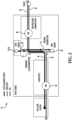
- Fig. 1 shows a block diagram of a beam director system 10 for a high-energy laser (HEL) weapon 12.
- the system 10 includes several beams that have different characteristics and are used for different purposes, as explained further below.
- the beams are passed through optical elements, represented schematically by blocks 20, 22, 24, 26, 28, and 30.
- Each of the blocks 20, 22, 24, 26, 28, and 30 represents any individual or combination of possible optical elements, including reflective elements such as mirrors, transmissive elements such as lenses or filters, beam splitters, expanders, and/or other optical elements.
- a series of light beams (or light from light sources) 32, 34, 36, and 38 pass through all or some of the blocks 20, 22, 24, 26, 28, and 30.
- the direction of movement through the blocks 20, 22, 24, 26, 28, and 30, in that order, is described herein as a downstream direction. This is the direction in which beams or other light are processed after being produced within the system 10, and then emitted from the system 10.
- This downstream direction is the direction that light travels from at least some light sources within the system 10.
- the opposite direction, in which light entering the system 10 from outside is referred to as the upstream direction.
- the light beams include an HEL beam 32, an auto-alignment beam 34, a target or boresight illuminator beam 36, and imaging light 38 from an imaging source.
- the high-energy laser beam 32, the auto-alignment beam 34, and the target or boresight illuminator beam 36 all may be sent from various laser or other light sources 42, for example including an HEL beam source for the HEL beam 32.
- Some or all of the beams 32, 34, and 36 may be initially misaligned, for example being misaligned angularly and/or spatially.
- the beams 32, 34, and 36 first pass through the beam correction block 20 which can be used to correct the misalignment of some or all of the beams 32, 34, and 36.
- the beam correction block 20 may include fast steering mirrors (FSMs) that can be controlled to correct at least some of the misalignment of the beams 32, 34, and 36.
- the block 20 may include two FSMs that are able to generate four degrees of freedom, two spatial (translational) and two angular, that are usable in correcting at least some of the misalignment of the beams 32, 34, and 36.
- FSMs fast steering mirrors
- the block 20 may include two FSMs that are able to generate four degrees of freedom, two spatial (translational) and two angular, that are usable in correcting at least some of the misalignment of the beams 32, 34, and 36.
- Other devices and/or mechanisms for correcting beam misalignment are possible.
- the block 22 represents a location where the target or boresight illuminator beam (or other beam used to meet mission parameters) 36 may be picked off (diverted). This is an optional feature, and in an alternative embodiment the pickoff block 22 may be omitted.
- the target or boresight illuminator beam 36 may be used to illuminate the target during firing of the HEL beam 32, to maintain target acquisition during the laser heating process.
- the beam 36 may be a lower-power high-divergence target illuminating laser, and target tracking during its use (described below) may be pared down the tracking to only that the wavelength that the beam 36 uses.
- the block 24 represents a location where an incoming light beam 38 is directed to a high-speed tracking sensor 50.
- the light from an external light source 38 travels in the opposite direction from the beams 32, 34, and 36, right to left in Fig. 1 .
- the light 38 reached the tracking sensor pickoff block 24 after passing through (in order) the output optics in block 30, the high-speed tracking correction in block 28, and the beam correction pickoff block 26.
- the light 38 is return light, a reflection off of the target from illumination by one or more other beams emitted by the system 10, such as a reflection from the target illuminator beam 36, for the purpose of tracking of the target.
- the light 38 may be passively tracked light from a target or other object, without illumination from the system 10.
- the target illuminator beam 36 may be a low-power laser beam following at least part of the same path and directed through at least some of the same optics as the high-energy laser beam 32.
- the target illuminator beam 36 may exit the system 10 without passing through all of the same optics as the high-energy laser beam 32.
- the target illuminator beam 36 may be 50-watt illuminator that exits the system 10 without passing through an expansion portion of the optics.
- the target illuminator beam 36 may have other characteristics and/or functions, for example being a target illuminator beam, range-finding beam, and/or dazzler.
- the tracking sensor 50 may be any of a variety of cameras or other sensors for target acquisition and tracking.
- the tracking sensor 50 may be a 30 Hz camera, for example capable of detecting short-wavelength infrared (SWIR) and/or near infrared (NIR) radiation.
- Output from the tracking sensor 50 may be used to provide imaging feedback and/or to position the HEL beam 32 on the target.
- SWIR short-wavelength infrared
- NIR near infrared
- the block 26 represents a location where the auto-alignment beam 34 is directed to the beam correction sensors 54 and 56.
- the sensors 54 and 56 provide measurements of angular and spatial beam error.
- the beam 34 may represent part of the HEL laser beam that is sent to the sensors 54 and 56 for determining appropriate correction.
- the auto-correction beam 34 is intended to be interpreted broadly to include a part of the main HEL beam 32.
- the block 28 is for high-speed tracking correction block, where correction devices, such as fast steering mirrors, are used to correct any deficiencies in the beam error, such as errors introduced by misaligned optical elements.
- correction block 28 uses as an input data from the sensors 54 and 56 to guide the fast steering mirrors.
- Fig. 2 shows some more detail about innovative aspects of the optical system 10, showing retroreflection between beam splitters 72 and 74.
- the beam splitters 72 and 74 are used to direct beams to the tracking sensor 50, and the beam correction sensors 54 and 56.
- the beam splitter 72 may be an HEL/SWIR beam splitter, which reflects the HEL beam 32 while splitting the short-wavelength infrared (SWIR) return light 38.
- the beam splitter 74 reflects the HEL beam 32 and the return light 38, while letting through the auto alignment beam 34, which may be an SWIR or a mid-wavelength infrared (MWIR) beam.
- SWIR short-wavelength infrared
- the auto-alignment beam 34 is retro-reflected in a constant or selective way at a retro-reflector 78, which for example may be a switchable retro-cube, to tie together the output of both of the sensor systems (the tracking sensor 50, and the beam correction sensors 54 and 56). This tying together facilitates thermal correction in the sensor portions of the system 10.
- a retro-reflector 78 which for example may be a switchable retro-cube, to tie together the output of both of the sensor systems (the tracking sensor 50, and the beam correction sensors 54 and 56). This tying together facilitates thermal correction in the sensor portions of the system 10.
- the tracking sensor 50 may be an SWIR sensor, or other sensor configured to detect an appropriate wavelength or range of wavelengths.
- the sensor 50 is operatively coupled to FSM 90 to control the FSM 90.
- the beam correction sensors 54 and 56 may be part of a laser beam optical positioning system, operatively coupled to FSM 94 for controlling the FSM 94.
- Fig. 3 shows further details of the system 10, shown in a schematic arrangement.
- the schematic arrangement shown in Fig. 3 is an example purely for purposes of illustration, and it will be appreciated that the number, type, and arrangement of elements may vary for other embodiments of the system 10.
- the light source 42 is the source for input beams 32, 34, and 36 into the system 10.
- the beams 32-36 pass through a first beam correction at 118, then through a coudé path 120 before encountering a second beam correction 122.
- An aperture sharing element 123 is used to pickoff the beam 36, which is then sent through pickoff optics 124.
- the beams 34 and 36 proceed through an internal optical path 125 and to aperture sharing elements 128 and 130.
- the aperture sharing elements 128 and 130 sends incoming imaging light 38 to a pair of cameras 132 and 134.
- the aperture sharing element 130 also directs the auto-alignment beam 34 to beam sensing cameras 140.
- the HEL beam 32 passes through the aperture sharing elements 128 and 130 to the beam correction 28, and then through output optics 30. From there the HEL beam 32 passes out of the system 10.
- the various parts of the system 10 may include various types of optical elements.
- optical elements may include combinations of mirrors, beam splitters, lenses, beam expanders, focusing elements, beam directors, optical scrapers, and switches, to give a non-exhaustive list of possible elements.
- the system 10 has the advantage that it can be used with any of a variety of high-energy lasers.
- any HEL that includes a co-boresighted and aligned alignment laser would be suitable for use in the system 10.
- Another advantage is in the modularity and simplification of the tracking algorithm that is used.
- the field of view (FOV) of the system 10 may be improved.
- another advantage may be in the retro-reflection provided by the retro-reflector 78, which may allow for beam aimpoint analysis in the sensor 50.
- the system 10 can actively link the beam correction sensor pointing solution from the beam correction sensors 54 and 56 to the pointing solution of tracking sensor 50 over time, temperature, shock, or other conditions detrimental to maintain key boresight requirements.
- the high speed track correction can be solely accomplished by the FSM 90 rather than having to couple in beam correction into the FSM 94, which would convolute the results from the tracking sensor 50, and the beam correction sensors 54 and 56.
- Fig. 4 shows an example packaging of the weapon 12, within a spherical casing 110, with a mount 112.
- Figs. 5-7 show three possible installations of the packaging shown in Fig. 4.
- Fig. 5 shows the casing 110 mounted on a helicopter 120.
- Fig. 6 shows the casing 110 mounted on a stationary installation 120.
- Fig. 7 shows the casing 110 mounted in a land vehicle 130.
- Many other installations/mountings are possible, for example on buildings or other stationary structures, on land vehicles of various types, on water vehicles of different types, and on aerospace vehicles (air or space) of many sorts.
Description
- The invention is in the field of high-energy laser weapons.
- Directed energy weapons pose special problems with regard to beam direction, for example having poor performance for intelligence, surveillance, and reconnaissance (ISR) systems, limited fields of view (FOVs) for tracking sensors, and/or poor boresight performance. Non-monostatic designs generally do not have good boresight maintenance due to parallax and consistently have issues with holding a beam on-target for sufficient periods to match lethality modeling. In addition systems may require complicated optical measurement to provide high speed safety for high-energy laser (HEL) optics. There may also be problems in holding an energy weapon on target for a sufficient time to disable or destroy a target.
- Accordingly there is room for improvement in the field of directed-energy weapons such as those involving high-energy lasers.
-
US 2003/062468 A1 discloses a beam control system and method which utilizes the wavefront reversal property of nonlinear optical phase conjugation to permit incorporation of a liquid crystal OPA within the low power legs of the beam control system, thereby affording the advantages of the OPA without the power limitations thereof. The invention is adapted for use with a beacon for illuminating a target with a first beam of electromagnetic energy. The system includes a telescope for receiving a target return comprising a reflection of the first beam from the target. An optical phased array is included for correcting for aberrations in the wavefront of the target return. A mechanism is included for ascertaining the correction applied by the optical phased array to the target return. The mechanism applies the correction to a third beam which ultimately is the output beam. In an embodiment, the first beam of electromagnetic energy is optical energy and the mechanism includes a first phase conjugate mirror adapted to conjugate electromagnetic energy output by the third mechanism and a second phase conjugate mirror adapted to conjugate the output of the first phase conjugate mirror. The fourth mechanism further includes an amplifier for boosting the signal output by the second phase conjugate mirror to provide the output beam. -
US 2012/018614 A1 discloses a high-energy beam that is precompensated by a process including receiving a high-energy beam from a source and energy from a target. The target energy includes wavefront aberrations related to atmospheric and other external disturbances encountered along a distance separating the target. A correction signal is determined responsive to the high-energy beam and the target energy. The correction signal is also configured to pre-compensate for wavefront aberrations related to the atmospheric and other external disturbances and to cancel aberrations introduced by the adaptive optics techniques. A wavefront of the outcoupled high-energy beam is adjusted responsive to the determined correction signal. A beam control system includes three adaptive optics servo loops and an aperture-sharing element. The arrangement is adapted to self-cancel internal optical-path-difference errors in the outcoupled beam and to pre-compensate the outcoupled beam according to a conjugate of the wavefront aberrations related to atmospheric and other external disturbances. -
US 8 218 589 B1 discloses a high-energy laser weapon system in which the high-energy laser beam itself is used to correct for atmospheric fluctuations thereby replacing a separate beacon illuminator system. The high-energy laser is turned off (negative pulse) periodically for a very short period giving a wavefront sensor an opportunity to measure the return of the high-energy laser beam from the target. A wavefront sensor drives a deformable mirror based on this return signal avoiding wavelength anisoplanatism. In addition, the high-energy laser weapon can be snapped ahead of the path of the target during the negative pulse to avoid tilt anisoplanitism. -
DE 32 02 432 A1 discloses a high-energy laser fine tracker, the HEL laser of which is associated with a directional laser and a HEL beam divider, the beam of which, having thewavelength lambda 2, is coupled in with the HEL beam having thewavelength lambda 1, and both beams are directed onto the target point via telescope optics and the reflected light, having thewavelength lambda 2, is focused onto a quadrant detector, the output signals of which are input to the detector of electronics for controlling the tilting mirror for this centre focusing, and thus the advantages of hot-spot tracking and of glint-tracking are retained but their disadvantages are avoided. -
US 4 102 572 A discloses dual-wavelength coherent optical adaptive systems which comprises means for adaptively forming a first beam of a first wavelength, on a target and for deriving therefrom information defining characteristics of phase perturbations in the propagation path to the target; and means responsive to said information for compensating for propagation path distortions for a second beam of a second wavelength which is simultaneously transmitted along a substantially identical path to that of said first beam. -
US 2011/103410 A1 discloses a laser beam control system including an output aperture through which a laser beam is directed toward a target. A laser beam return is also received through the output aperture, with the laser beam return including scatter from the laser beam. A deformable mirror is adapted to control the outgoing laser beam, and a sensor is adapted to detect the wavefront of the laser beam return. An optics controller is operationally coupled to the deformable mirror and is adapted to adjust the deformable mirror in response to the wavefront of the laser beam return. - A high-energy laser weapon system has optical tracking throughout a full optical path of the system.
- A high-energy laser weapon system has optical tracking that covers all optical element of an optical path through the system. The optical path may handle multiple beams over at least parts of its path, including a high-energy laser beam, as well as one or more additional beams, such a target-tracking beam.
- A high-energy laser weapon system has retro-reflection through part of its optical path, enabling beam aimpoint analysis in a high-speed track sensor.
- A high-energy laser weapon system provides for stabilized co-aligned beams traveling along a common optical path.
- According to a first aspect of the invention, the present disclosure provides a beam director system for a high energy laser, HEL, weapon according to
claim 1, the system comprising: an HEL beam source for an HEL beam; output optics downstream of the HEL beam source; first beam correction elements downstream of the HEL beam source; second beam correction elements downstream of the HEL beam source, and upstream of the output optics; and one or more beam correction sensors and one or more tracking sensors; and a source for a target illuminator beam, range-finding beam, and/or dazzler, for providing an additional beam for tracking the target; and a pickoff that is configured to divert the target illuminator beam, range-finding beam, and/or dazzler from an optical path followed by the HEL beam; wherein the one or more beam correction sensors and the one or more tracking sensors are downstream of the first beam correction elements and are upstream of the second beam correction elements; and wherein the target illuminator beam, range-finding beam, and/or dazzler is configured to pass through the first beam correction elements. - According to an embodiment of any paragraph(s) of this summary, the one or more beam correction sensors are downstream of the one or more tracking sensors.
- According to an embodiment of any paragraph(s) of this summary, the one or more beam correction sensors may include: a sensor of angular beam error; and a sensor of spatial beam error.
- According to an embodiment of any paragraph(s) of this summary, the one or more tracking sensors are operatively coupled to beam correction elements controlling the HEL beam.
- According to an embodiment of any paragraph(s) of this summary, the one or more tracking sensors are operatively coupled to the second beam correction elements to effect target tracking of a target.
- According to an embodiment of any paragraph(s) of this summary, the second beam correction elements include a fast steering mirror.
- According to an embodiment of any paragraph(s) of this summary, the second beam correction elements include a fast steering element.
- According to an embodiment of any paragraph(s) of this summary, the second beam correction elements include a slow steering mirror.
- According to an embodiment of any paragraph(s) of this summary, the second beam correction elements include an adaptive optic.
- According to an embodiment of any paragraph(s) of this summary, the first beam correction elements include at least two steering mirrors.
- According to an embodiment of any paragraph(s) of this summary, the first beam correction elements include at least two steering elements.
- According to an embodiment of any paragraph(s) of this summary, the first beam correction elements include one or more adaptive optics.
- According to an embodiment of any paragraph(s) of this summary, the first beam correction elements include correction with at least four degrees of freedom.
- According to an embodiment of any paragraph(s) of this summary, the at least four degrees of freedom include at least two angular degrees of freedom, and at least two spatial degrees of freedom.
- According to an embodiment of any paragraph(s) of this summary, the one or more beam correction sensors are operatively coupled to the first beam correction elements, to correct for errors in positioning of the HEL beam.
- According to an embodiment of any paragraph(s) of this summary, the HEL beam source also emits an auto-alignment beam that is co-aligned with the HEL beam.
- According to an embodiment of any paragraph(s) of this summary, the system further includes an upstream beam splitter and a downstream beam splitter; wherein the upstream beam splitter is upstream of the downstream beam splitter; and wherein the downstream beam splitter directs part of the auto-alignment beam to the one or more beam correction sensors.
- According to an embodiment of any paragraph(s) of this summary, the system further includes a retroreflector.
- According to an embodiment of any paragraph(s) of this summary, the retroreflector directs part of the auto-alignment back to the one or more track sensors.
- According to an embodiment of any paragraph(s) of this summary, the system further includes a laser source for providing an additional laser beam for tracking the target.
- According to an embodiment of any paragraph(s) of this summary, the additional laser beam passes through the first beam correction elements.
- According to an embodiment of any paragraph(s) of this summary, the pickoff is downstream of the first beam correction elements and is upstream of the second beam correction elements.
- According to another aspect of the invention, the present disclosure provides a method of operating a high-energy laser, HEL, weapon according to
claim 12, the method comprising: sending an HEL beam of the HEL weapon through optics that are optically downstream of an HEL beam source of the HEL weapon; and correcting the path of the HEL beam that has passed through the optics, using first beam correction elements and second beam correction elements of the HEL weapon, wherein the first beam correction elements and the second beam correction elements are optically downstream of the HEL beam source; wherein the correcting of the optics is based at least in part on output from one or more beam correction sensors and/or one or more tracking sensors of the HEL weapon, wherein the one or more beam correction sensors and/or the one or more tracking sensors are downstream of the first beam correction elements and are upstream of the second beam correction elements and further comprising: using a source for a target illuminator beam, range-finding beam, and/or dazzler; sending a target illuminator beam, range-finding beam, and/or dazzler for providing an additional beam for tracking the target, through the first beam correction elements; and diverting the target illuminator beam, range-finding beam, and/or dazzler from an optical path followed by the HEL beam using a pickoff. - According to an embodiment of any paragraph(s) of this summary, the method further includes operatively coupling the one or more beam correction sensors and the one or more tracking sensors together.
- According to an embodiment of any paragraph(s) of this summary, the operatively coupling includes reflecting an alignment beam from between the one or more beam correction sensors and the one or more tracking sensors.
- According to an embodiment of any paragraph(s) of this summary, the method further includes overlapping beams received by the one or more beam correction sensors and the one or more tracking sensors.
- According to an embodiment of any paragraph(s) of this summary, the correcting the optics includes changing position of one or more fast steering elements of the one or more first beam correction elements, and changing position of one or more fast steering elements of the one or more second beam correction elements.
- To the accomplishment of the foregoing and related ends, the invention comprises the features hereinafter fully described and particularly pointed out in the claims. The following description and the annexed drawings set forth in detail certain illustrative embodiments of the invention. These embodiments are indicative, however, of but a few of the various ways in which the principles of the invention may be employed. Other objects, advantages and novel features of the invention will become apparent from the following detailed description of the invention when considered in conjunction with the drawings.
- The annexed drawings, which are not necessarily to scale, show various aspects of the invention.
-
Fig. 1 is a block diagram of a beam director system according to an embodiment of the invention. -
Fig. 2 is a schematic diagram of part of the beam director system ofFig. 1 . -
Fig. 3 is a schematic diagram of a high-energy laser (HEL) weapon that includes a beam director system, according to an embodiment of the invention. -
Fig. 4 is an oblique view of a housing that encloses (and is part of) an HEL weapon, according to an embodiment of the invention. -
Fig. 5 shows an HEL weapon, an embodiment of the invention, mounted on a helicopter. -
Fig. 6 shows an HEL weapon, an embodiment of the invention, mounted on a stationary structure. -
Fig. 7 shows an HEL weapon, an embodiment of the invention, mounted on a land vehicle. - A beam director system for a high-energy laser (HEL) weapon includes correction sensors that are able detect misalignments in optical elements throughout the entire optical path traversed by the high-energy laser. The system includes beam correction sensors that sense misalignments in a first part of the optical path, and high-speed track sensors that sense misalignments in a second part of the optical path, with the first part and the second part overlapping. This allows all optics to be sensed by the beam correction sensors and/or the high-speed track sensors. Any critical optical failure is thus promptly detected. The system can accommodate a wide variety of lasers for the HEL, preferably including a co-boresighted and aligned alignment laser. In addition the system may include provisions that simplify a tracking algorithm, for example by driving a steering mirror or other optical correction device directly from the high-speed track sensor. By having the track sensors further downstream on the optical path than in prior devices, the acquisition and trace sensor fields of view of the system may be improved.
-
Fig. 1 shows a block diagram of abeam director system 10 for a high-energy laser (HEL)weapon 12. Thesystem 10 includes several beams that have different characteristics and are used for different purposes, as explained further below. The beams are passed through optical elements, represented schematically byblocks blocks - A series of light beams (or light from light sources) 32, 34, 36, and 38 pass through all or some of the
blocks blocks system 10, and then emitted from thesystem 10. This downstream direction is the direction that light travels from at least some light sources within thesystem 10. The opposite direction, in which light entering thesystem 10 from outside (such as light reflected off of a target) is referred to as the upstream direction. - The light beams include an
HEL beam 32, an auto-alignment beam 34, a target orboresight illuminator beam 36, and imaging light 38 from an imaging source. In the illustrated embodiment the high-energy laser beam 32, the auto-alignment beam 34, and the target orboresight illuminator beam 36 all may be sent from various laser or otherlight sources 42, for example including an HEL beam source for theHEL beam 32. Some or all of thebeams beams beam correction block 20 which can be used to correct the misalignment of some or all of thebeams beam correction block 20 may include fast steering mirrors (FSMs) that can be controlled to correct at least some of the misalignment of thebeams block 20 may include two FSMs that are able to generate four degrees of freedom, two spatial (translational) and two angular, that are usable in correcting at least some of the misalignment of thebeams - The
block 22 represents a location where the target or boresight illuminator beam (or other beam used to meet mission parameters) 36 may be picked off (diverted). This is an optional feature, and in an alternative embodiment thepickoff block 22 may be omitted. In a non-limiting example the target orboresight illuminator beam 36 may be used to illuminate the target during firing of theHEL beam 32, to maintain target acquisition during the laser heating process. Thebeam 36 may be a lower-power high-divergence target illuminating laser, and target tracking during its use (described below) may be pared down the tracking to only that the wavelength that thebeam 36 uses. - The block 24 represents a location where an
incoming light beam 38 is directed to a high-speed tracking sensor 50. The light from an external light source 38 (from a target) travels in the opposite direction from thebeams Fig. 1 . The light 38 reached the tracking sensor pickoff block 24 after passing through (in order) the output optics inblock 30, the high-speed tracking correction inblock 28, and the beamcorrection pickoff block 26. The light 38 is return light, a reflection off of the target from illumination by one or more other beams emitted by thesystem 10, such as a reflection from thetarget illuminator beam 36, for the purpose of tracking of the target. Alternatively the light 38 may be passively tracked light from a target or other object, without illumination from thesystem 10. Thetarget illuminator beam 36 may be a low-power laser beam following at least part of the same path and directed through at least some of the same optics as the high-energy laser beam 32. Thetarget illuminator beam 36 may exit thesystem 10 without passing through all of the same optics as the high-energy laser beam 32. For example thetarget illuminator beam 36 may be 50-watt illuminator that exits thesystem 10 without passing through an expansion portion of the optics. Alternatively or in addition thetarget illuminator beam 36 may have other characteristics and/or functions, for example being a target illuminator beam, range-finding beam, and/or dazzler. - The tracking
sensor 50 may be any of a variety of cameras or other sensors for target acquisition and tracking. In one embodiment the trackingsensor 50 may be a 30 Hz camera, for example capable of detecting short-wavelength infrared (SWIR) and/or near infrared (NIR) radiation. Output from the trackingsensor 50 may be used to provide imaging feedback and/or to position theHEL beam 32 on the target. - The
block 26 represents a location where the auto-alignment beam 34 is directed to thebeam correction sensors 54 and 56. Thesensors 54 and 56 provide measurements of angular and spatial beam error. Alternatively thebeam 34 may represent part of the HEL laser beam that is sent to thesensors 54 and 56 for determining appropriate correction. The auto-correction beam 34 is intended to be interpreted broadly to include a part of themain HEL beam 32. - The
block 28 is for high-speed tracking correction block, where correction devices, such as fast steering mirrors, are used to correct any deficiencies in the beam error, such as errors introduced by misaligned optical elements. Thecorrection block 28 uses as an input data from thesensors 54 and 56 to guide the fast steering mirrors. - It is an important advantage of the system that all of the optics in the blocks 20-30 are subject to monitoring by the sensors and correction by the correction portions. All of the optical elements are sensed by at least the
sensor 50, or thesensors 54 and 56. -
Fig. 2 shows some more detail about innovative aspects of theoptical system 10, showing retroreflection betweenbeam splitters beam splitters sensor 50, and thebeam correction sensors 54 and 56. Thebeam splitter 72 may be an HEL/SWIR beam splitter, which reflects theHEL beam 32 while splitting the short-wavelength infrared (SWIR) returnlight 38. Thebeam splitter 74 reflects theHEL beam 32 and thereturn light 38, while letting through theauto alignment beam 34, which may be an SWIR or a mid-wavelength infrared (MWIR) beam. The auto-alignment beam 34 is retro-reflected in a constant or selective way at a retro-reflector 78, which for example may be a switchable retro-cube, to tie together the output of both of the sensor systems (the trackingsensor 50, and the beam correction sensors 54 and 56). This tying together facilitates thermal correction in the sensor portions of thesystem 10. - As shown in
Fig. 2 , the trackingsensor 50 may be an SWIR sensor, or other sensor configured to detect an appropriate wavelength or range of wavelengths. Thesensor 50 is operatively coupled toFSM 90 to control theFSM 90. Thebeam correction sensors 54 and 56 may be part of a laser beam optical positioning system, operatively coupled toFSM 94 for controlling theFSM 94. -
Fig. 3 shows further details of thesystem 10, shown in a schematic arrangement. The schematic arrangement shown inFig. 3 is an example purely for purposes of illustration, and it will be appreciated that the number, type, and arrangement of elements may vary for other embodiments of thesystem 10. - The
light source 42 is the source for input beams 32, 34, and 36 into thesystem 10. The beams 32-36 pass through a first beam correction at 118, then through acoudé path 120 before encountering asecond beam correction 122. - An
aperture sharing element 123 is used to pickoff thebeam 36, which is then sent throughpickoff optics 124. Thebeams optical path 125 and toaperture sharing elements aperture sharing elements incoming imaging light 38 to a pair ofcameras 132 and 134. Theaperture sharing element 130 also directs the auto-alignment beam 34 tobeam sensing cameras 140. - The
HEL beam 32 passes through theaperture sharing elements beam correction 28, and then throughoutput optics 30. From there theHEL beam 32 passes out of thesystem 10. - The various parts of the
system 10 may include various types of optical elements. Such optical elements may include combinations of mirrors, beam splitters, lenses, beam expanders, focusing elements, beam directors, optical scrapers, and switches, to give a non-exhaustive list of possible elements. - The
system 10 has the advantage that it can be used with any of a variety of high-energy lasers. In general, any HEL that includes a co-boresighted and aligned alignment laser would be suitable for use in thesystem 10. - Another advantage is in the modularity and simplification of the tracking algorithm that is used. There may be a simplified stabilization paradigm used to drive the fast-steering mirror(s) 90 of
block 28 directly from thesensor 50. - By moving the tracking
sensor 50 further downstream than in some prior systems, the field of view (FOV) of thesystem 10 may be improved. In addition, another advantage may be in the retro-reflection provided by the retro-reflector 78, which may allow for beam aimpoint analysis in thesensor 50. By utilization of the retro-reflection from the retro-reflector 78, thesystem 10 can actively link the beam correction sensor pointing solution from thebeam correction sensors 54 and 56 to the pointing solution of trackingsensor 50 over time, temperature, shock, or other conditions detrimental to maintain key boresight requirements. - Finally, using a common input beam stabilization for all the input beams (from the
FSM 94, for example) offloads the high-speed tracking error for auxiliary beams. As the beams have already been corrected onto the beam director optical bench by theFSM 94 by thebeam correction sensors 54 and 56, the high speed track correction can be solely accomplished by theFSM 90 rather than having to couple in beam correction into theFSM 94, which would convolute the results from the trackingsensor 50, and thebeam correction sensors 54 and 56. -
Fig. 4 shows an example packaging of theweapon 12, within aspherical casing 110, with amount 112.Figs. 5-7 show three possible installations of the packaging shown inFig. 4. Fig. 5 shows thecasing 110 mounted on ahelicopter 120.Fig. 6 shows thecasing 110 mounted on astationary installation 120.Fig. 7 shows thecasing 110 mounted in aland vehicle 130. Many other installations/mountings are possible, for example on buildings or other stationary structures, on land vehicles of various types, on water vehicles of different types, and on aerospace vehicles (air or space) of many sorts. - Although the invention has been shown and described with respect to a certain preferred embodiment or embodiments, it is obvious that equivalent alterations and modifications within the scope of the appended claims will occur to others skilled in the art upon the reading and understanding of this specification and the annexed drawings. In particular regard to the various functions performed by the above described elements (components, assemblies, devices, compositions, etc.), the terms (including a reference to a "means") used to describe such elements are intended to correspond, unless otherwise indicated, to any element which performs the specified function of the described element (i.e., that is functionally equivalent), even though not structurally equivalent to the disclosed structure which performs the function in the herein illustrated exemplary embodiment or embodiments of the invention. In addition, while a particular feature of the invention may have been described above with respect to only one or more of several illustrated embodiments, such feature may be combined within the scope of the appended claims with one or more other features of the other embodiments, as may be desired and advantageous for any given or particular application.
Claims (15)
- A beam director system (10) for a high energy laser, HEL, weapon, the system comprising:an HEL beam source for an HEL beam (32);output optics (30) downstream of the HEL beam source;first beam correction elements (20, 118) downstream of the HEL beam source;second beam correction elements (28, 122) downstream of the HEL beam source, and upstream of the output optics;one or more beam correction sensors (54, 56) and one or more tracking sensors (50); anda source (42) for a target illuminator beam, range-finding beam, and/or dazzler, for providing an additional beam for tracking the target; anda pickoff (22, 123) that is configured to divert the target illuminator beam, range-finding beam, and/or dazzler from an optical path followed by the HEL beam;wherein the one or more beam correction sensors and the one or more tracking sensors are downstream of the first beam correction elements and are upstream of the second beam correction elements; andwherein the target illuminator beam (36), range-finding beam, and/or dazzler is configured to pass through the first beam correction elements.
- The system of claim 1, wherein the one or more beam correction sensors are downstream of the one or more tracking sensors.
- The system of claim 1, or of claim 1 or claim 2,
wherein the one or more beam correction sensors include:a sensor of angular beam error; and/ora sensor of spatial beam error. - The system of claim 1, or of any of claims 1 to 3, wherein the one or more tracking sensors are operatively coupled to the second beam correction elements to effect target tracking of a target.
- The system of claim 1, or of any of claims 1 to 4, wherein the second beam correction elements include a fast steering mirror.
- The system of claim 1, or of any of claims 1 to 5, wherein the first beam correction elements include at least two steering elements.
- The system of claim 1, or of any of claims 1 to 6, wherein the first beam correction elements include correction with at least four degrees of freedom; and
preferably, wherein the at least four degrees of freedom include at least two angular degrees of freedom, and at least two spatial degrees of freedom. - The system of claim 1, or of any of claims 1 to 7, wherein the one or more beam correction sensors are operatively coupled to the first beam correction elements, to correct for errors in positioning of the HEL beam.
- The system of claim 1, or of any of claims 1 to 8, wherein the HEL beam source also emits an auto-alignment beam (34) that is co-aligned with the HEL beam; andpreferably, further comprising an upstream beam splitter (72) and a downstream beam splitter (74);wherein the upstream beam splitter is upstream of the downstream beam splitter; andwherein the downstream beam splitter directs part of the auto-alignment beam to the one or more beam correction sensors.
- The system of claim 9, further comprising a retroreflector;
wherein the retroreflector directs part of the auto-alignment back to the one or more track sensors. - The system of claim 1, wherein the pickoff is downstream of the first beam correction elements and is upstream of the second beam correction elements.
- A method of operating a high-energy laser, HEL, weapon, the method comprising:sending an HEL beam (32) of the HEL weapon through optics (30) that are optically downstream of an HEL beam source of the HEL weapon; andcorrecting the path of the HEL beam that has passed through the optics, using first beam correction elements (20, 118) and second beam correction elements (28, 122) of the HEL weapon, wherein the first beam correction elements and the second beam correction elements are optically downstream of the HEL beam source;wherein the correcting of the optics is based at least in part on output from one or more beam correction sensors (54, 56) and/or one or more tracking sensors (50) of the HEL weapon, wherein the one or more beam correction sensors and/or the one or more tracking sensors are downstream of the first beam correction elements and are upstream of the second beam correction elements; andfurther comprising:using a source for a target illuminator beam, range-finding beam, and/or dazzler; sending the target illuminator beam, range-finding beam, and/or dazzler, for providing an additional beam for tracking the target, through the first beam correction elements; anddiverting the target illuminator beam, range-finding beam, and/or dazzler from an optical path followed by the HEL beam using a pickoff (22, 123).
- The method of claim 12,further comprising operatively coupling the one or more beam correction sensors and the one or more tracking sensors together;wherein the operatively coupling includes reflecting an alignment beam from between the one or more beam correction sensors and the one or more tracking sensors.
- The method of claim 12, or of claim 12 or claim 13, further comprising overlapping beams (34, 36) received by the one or more beam correction sensors and the one or more tracking sensors.
- The method of claim 12, or of any of claims 12 to 14, wherein correcting the optics includes changing position of one or more fast steering mirrors of the one or more first beam correction elements, and changing position of one or more fast steering mirrors of the one or more second beam correction elements.
Applications Claiming Priority (2)
| Application Number | Priority Date | Filing Date | Title |
|---|---|---|---|
| US16/406,414 US11342721B1 (en) | 2019-05-08 | 2019-05-08 | Beam director for high-energy laser (HEL) weapon |
| PCT/US2020/019242 WO2020226721A1 (en) | 2019-05-08 | 2020-02-21 | Beam director for high-energy laser (hel) weapon |
Publications (2)
| Publication Number | Publication Date |
|---|---|
| EP3966516A1 EP3966516A1 (en) | 2022-03-16 |
| EP3966516B1 true EP3966516B1 (en) | 2023-08-09 |
Family
ID=71899806
Family Applications (1)
| Application Number | Title | Priority Date | Filing Date |
|---|---|---|---|
| EP20750379.8A Active EP3966516B1 (en) | 2019-05-08 | 2020-02-21 | Beam director for high-energy laser (hel) weapon |
Country Status (8)
| Country | Link |
|---|---|
| US (1) | US11342721B1 (en) |
| EP (1) | EP3966516B1 (en) |
| JP (1) | JP7241206B2 (en) |
| KR (1) | KR102627589B1 (en) |
| FI (1) | FI3966516T3 (en) |
| IL (1) | IL287722B (en) |
| PL (1) | PL3966516T3 (en) |
| WO (1) | WO2020226721A1 (en) |
Families Citing this family (5)
| Publication number | Priority date | Publication date | Assignee | Title |
|---|---|---|---|---|
| US11342721B1 (en) | 2019-05-08 | 2022-05-24 | Raytheon Company | Beam director for high-energy laser (HEL) weapon |
| US11788822B2 (en) | 2020-07-23 | 2023-10-17 | Raytheon Company | Ultra-compact, modular laser sensor for tactical environments |
| KR102433017B1 (en) * | 2022-01-26 | 2022-08-18 | 한화시스템(주) | system for aiming target in laser weapon and method of aiming using the same |
| KR102653391B1 (en) * | 2022-07-08 | 2024-04-01 | 엘아이지넥스원 주식회사 | Dual mode seeking apparatus and guided weapon with the same |
| KR102654938B1 (en) * | 2023-08-11 | 2024-04-03 | 국방과학연구소 | Aircraft comprising retro-reflector and method for neutralizing laser weapon using the same |
Family Cites Families (16)
| Publication number | Priority date | Publication date | Assignee | Title |
|---|---|---|---|---|
| US4102572A (en) | 1977-08-11 | 1978-07-25 | Hughes Aircraft Company | Dual-wavelength coherent optical adaptive systems |
| DE3202432A1 (en) | 1982-01-26 | 1983-08-04 | Messerschmitt-Bölkow-Blohm GmbH, 8000 München | High-energy laser fine tracker |
| US6424412B1 (en) | 2000-08-30 | 2002-07-23 | Sony Corporation | Efficient system and method for detecting and correcting laser misalignment of plural laser beams |
| US6809307B2 (en) | 2001-09-28 | 2004-10-26 | Raytheon Company | System and method for effecting high-power beam control with adaptive optics in low power beam path |
| US6765663B2 (en) | 2002-03-14 | 2004-07-20 | Raytheon Company | Efficient multiple emitter boresight reference source |
| US7230689B2 (en) | 2002-08-26 | 2007-06-12 | Lau Kam C | Multi-dimensional measuring system |
| US7236299B1 (en) | 2006-04-11 | 2007-06-26 | Bae Systems Information And Electronic Systems Integration Inc. | Compact periscopic beam director |
| US7626152B2 (en) | 2006-08-16 | 2009-12-01 | Raytheon Company | Beam director and control system for a high energy laser within a conformal window |
| US8218589B1 (en) | 2008-07-28 | 2012-07-10 | The United States Of America As Represented By The Secretary Of The Air Force | High-energy laser atmospheric compensation and aimpoint maintenance |
| US8415600B2 (en) | 2009-03-27 | 2013-04-09 | Optical Physics Company | Laser beam control system and method |
| US8203109B2 (en) | 2009-05-08 | 2012-06-19 | Raytheon Company | High energy laser beam director system and method |
| US8362410B2 (en) | 2010-07-26 | 2013-01-29 | Raytheon Company | Source-independent beam director and control system for a high-energy electromagnetic radiation source |
| IL234036B (en) | 2014-08-10 | 2018-11-29 | Rafael Advanced Defense Systems Ltd | Directed energy weapon |
| JP2016042550A (en) | 2014-08-19 | 2016-03-31 | 株式会社東芝 | Laser irradiation apparatus and laser irradiation method |
| US11073420B2 (en) | 2018-11-06 | 2021-07-27 | Raytheon Company | Active partial-beam alignment systems for sensor-to-laser boresight maintenance |
| US11342721B1 (en) | 2019-05-08 | 2022-05-24 | Raytheon Company | Beam director for high-energy laser (HEL) weapon |
-
2019
- 2019-05-08 US US16/406,414 patent/US11342721B1/en active Active
-
2020
- 2020-02-21 JP JP2021564779A patent/JP7241206B2/en active Active
- 2020-02-21 PL PL20750379.8T patent/PL3966516T3/en unknown
- 2020-02-21 EP EP20750379.8A patent/EP3966516B1/en active Active
- 2020-02-21 KR KR1020217035445A patent/KR102627589B1/en active IP Right Grant
- 2020-02-21 WO PCT/US2020/019242 patent/WO2020226721A1/en unknown
- 2020-02-21 FI FIEP20750379.8T patent/FI3966516T3/en active
-
2021
- 2021-10-31 IL IL287722A patent/IL287722B/en unknown
Also Published As
| Publication number | Publication date |
|---|---|
| PL3966516T3 (en) | 2024-02-05 |
| US11342721B1 (en) | 2022-05-24 |
| KR20210144872A (en) | 2021-11-30 |
| EP3966516A1 (en) | 2022-03-16 |
| JP7241206B2 (en) | 2023-03-16 |
| JP2022531322A (en) | 2022-07-06 |
| KR102627589B1 (en) | 2024-01-23 |
| IL287722A (en) | 2021-12-01 |
| US20220163296A1 (en) | 2022-05-26 |
| WO2020226721A1 (en) | 2020-11-12 |
| IL287722B (en) | 2022-04-01 |
| FI3966516T3 (en) | 2023-11-09 |
Similar Documents
| Publication | Publication Date | Title |
|---|---|---|
| EP3966516B1 (en) | Beam director for high-energy laser (hel) weapon | |
| US8421003B2 (en) | Optical transceiver built-in test (BIT) | |
| KR101057303B1 (en) | Tracking and aiming apparatus for laser weapon | |
| US10502951B2 (en) | High-performance beam director for high-power laser systems or other systems | |
| US6145784A (en) | Shared aperture dichroic active tracker with background subtraction | |
| US6021975A (en) | Dichroic active tracker | |
| JPH0236926B2 (en) | ||
| US20230161172A1 (en) | System and method for correcting for atmospheric jitter and high energy laser broadband interference using fast steering mirrors | |
| US10859348B1 (en) | System for active telescope alignment, focus and beam control | |
| US20220121035A1 (en) | OPTICAL SENSOR WITH Tx/Rx APERTURE SHARING ELEMENT (ASE) FOR PROCESSING PASSIVE AND ACTIVE SIGNALS | |
| US20220107490A1 (en) | OPTICAL SENSOR WITH Tx/Rx APERTURE SHARING ELEMENT (ASE) TO BLOCK DETECTION OF THE RECEIVED ACTIVE SIGNAL | |
| US11686820B2 (en) | Optical sensor with ring-shaped Tx/Rx aperture sharing element (ASE) | |
| US5410398A (en) | Automatic boresight compensation device | |
| US8531657B2 (en) | Micro-radian class line of sight and centration stabilization system | |
| US11788822B2 (en) | Ultra-compact, modular laser sensor for tactical environments | |
| RU2396573C2 (en) | Electro-optical sighting system | |
| US20230022548A1 (en) | OPTICAL SCANNING SYSTEM USING MICRO-ELECTRO-MECHANICAL SYSTEM (MEMS) MICRO-MIRROR ARRAYS (MMAs) | |
| JPH0996767A (en) | Spacial optical communicating device |
Legal Events
| Date | Code | Title | Description |
|---|---|---|---|
| STAA | Information on the status of an ep patent application or granted ep patent |
Free format text: STATUS: UNKNOWN |
|
| STAA | Information on the status of an ep patent application or granted ep patent |
Free format text: STATUS: THE INTERNATIONAL PUBLICATION HAS BEEN MADE |
|
| PUAI | Public reference made under article 153(3) epc to a published international application that has entered the european phase |
Free format text: ORIGINAL CODE: 0009012 |
|
| STAA | Information on the status of an ep patent application or granted ep patent |
Free format text: STATUS: REQUEST FOR EXAMINATION WAS MADE |
|
| 17P | Request for examination filed |
Effective date: 20211203 |
|
| AK | Designated contracting states |
Kind code of ref document: A1 Designated state(s): AL AT BE BG CH CY CZ DE DK EE ES FI FR GB GR HR HU IE IS IT LI LT LU LV MC MK MT NL NO PL PT RO RS SE SI SK SM TR |
|
| STAA | Information on the status of an ep patent application or granted ep patent |
Free format text: STATUS: EXAMINATION IS IN PROGRESS |
|
| DAV | Request for validation of the european patent (deleted) | ||
| DAX | Request for extension of the european patent (deleted) | ||
| 17Q | First examination report despatched |
Effective date: 20220720 |
|
| GRAJ | Information related to disapproval of communication of intention to grant by the applicant or resumption of examination proceedings by the epo deleted |
Free format text: ORIGINAL CODE: EPIDOSDIGR1 |
|
| GRAP | Despatch of communication of intention to grant a patent |
Free format text: ORIGINAL CODE: EPIDOSNIGR1 |
|
| GRAP | Despatch of communication of intention to grant a patent |
Free format text: ORIGINAL CODE: EPIDOSNIGR1 |
|
| STAA | Information on the status of an ep patent application or granted ep patent |
Free format text: STATUS: GRANT OF PATENT IS INTENDED |
|
| INTG | Intention to grant announced |
Effective date: 20230306 |
|
| GRAS | Grant fee paid |
Free format text: ORIGINAL CODE: EPIDOSNIGR3 |
|
| GRAA | (expected) grant |
Free format text: ORIGINAL CODE: 0009210 |
|
| STAA | Information on the status of an ep patent application or granted ep patent |
Free format text: STATUS: THE PATENT HAS BEEN GRANTED |
|
| AK | Designated contracting states |
Kind code of ref document: B1 Designated state(s): AL AT BE BG CH CY CZ DE DK EE ES FI FR GB GR HR HU IE IS IT LI LT LU LV MC MK MT NL NO PL PT RO RS SE SI SK SM TR |
|
| REG | Reference to a national code |
Ref country code: GB Ref legal event code: FG4D |
|
| REG | Reference to a national code |
Ref country code: CH Ref legal event code: EP |
|
| REG | Reference to a national code |
Ref country code: DE Ref legal event code: R096 Ref document number: 602020015517 Country of ref document: DE |
|
| REG | Reference to a national code |
Ref country code: IE Ref legal event code: FG4D |
|
| REG | Reference to a national code |
Ref country code: RO Ref legal event code: EPE |
|
| REG | Reference to a national code |
Ref country code: LT Ref legal event code: MG9D |
|
| REG | Reference to a national code |
Ref country code: NL Ref legal event code: MP Effective date: 20230809 |
|
| REG | Reference to a national code |
Ref country code: AT Ref legal event code: MK05 Ref document number: 1597985 Country of ref document: AT Kind code of ref document: T Effective date: 20230809 |
|
| PG25 | Lapsed in a contracting state [announced via postgrant information from national office to epo] |
Ref country code: GR Free format text: LAPSE BECAUSE OF FAILURE TO SUBMIT A TRANSLATION OF THE DESCRIPTION OR TO PAY THE FEE WITHIN THE PRESCRIBED TIME-LIMIT Effective date: 20231110 |
|
| PG25 | Lapsed in a contracting state [announced via postgrant information from national office to epo] |
Ref country code: IS Free format text: LAPSE BECAUSE OF FAILURE TO SUBMIT A TRANSLATION OF THE DESCRIPTION OR TO PAY THE FEE WITHIN THE PRESCRIBED TIME-LIMIT Effective date: 20231209 |
|
| PG25 | Lapsed in a contracting state [announced via postgrant information from national office to epo] |
Ref country code: SE Free format text: LAPSE BECAUSE OF FAILURE TO SUBMIT A TRANSLATION OF THE DESCRIPTION OR TO PAY THE FEE WITHIN THE PRESCRIBED TIME-LIMIT Effective date: 20230809 Ref country code: RS Free format text: LAPSE BECAUSE OF FAILURE TO SUBMIT A TRANSLATION OF THE DESCRIPTION OR TO PAY THE FEE WITHIN THE PRESCRIBED TIME-LIMIT Effective date: 20230809 Ref country code: PT Free format text: LAPSE BECAUSE OF FAILURE TO SUBMIT A TRANSLATION OF THE DESCRIPTION OR TO PAY THE FEE WITHIN THE PRESCRIBED TIME-LIMIT Effective date: 20231211 Ref country code: NO Free format text: LAPSE BECAUSE OF FAILURE TO SUBMIT A TRANSLATION OF THE DESCRIPTION OR TO PAY THE FEE WITHIN THE PRESCRIBED TIME-LIMIT Effective date: 20231109 Ref country code: NL Free format text: LAPSE BECAUSE OF FAILURE TO SUBMIT A TRANSLATION OF THE DESCRIPTION OR TO PAY THE FEE WITHIN THE PRESCRIBED TIME-LIMIT Effective date: 20230809 Ref country code: LV Free format text: LAPSE BECAUSE OF FAILURE TO SUBMIT A TRANSLATION OF THE DESCRIPTION OR TO PAY THE FEE WITHIN THE PRESCRIBED TIME-LIMIT Effective date: 20230809 Ref country code: LT Free format text: LAPSE BECAUSE OF FAILURE TO SUBMIT A TRANSLATION OF THE DESCRIPTION OR TO PAY THE FEE WITHIN THE PRESCRIBED TIME-LIMIT Effective date: 20230809 Ref country code: IS Free format text: LAPSE BECAUSE OF FAILURE TO SUBMIT A TRANSLATION OF THE DESCRIPTION OR TO PAY THE FEE WITHIN THE PRESCRIBED TIME-LIMIT Effective date: 20231209 Ref country code: HR Free format text: LAPSE BECAUSE OF FAILURE TO SUBMIT A TRANSLATION OF THE DESCRIPTION OR TO PAY THE FEE WITHIN THE PRESCRIBED TIME-LIMIT Effective date: 20230809 Ref country code: GR Free format text: LAPSE BECAUSE OF FAILURE TO SUBMIT A TRANSLATION OF THE DESCRIPTION OR TO PAY THE FEE WITHIN THE PRESCRIBED TIME-LIMIT Effective date: 20231110 Ref country code: AT Free format text: LAPSE BECAUSE OF FAILURE TO SUBMIT A TRANSLATION OF THE DESCRIPTION OR TO PAY THE FEE WITHIN THE PRESCRIBED TIME-LIMIT Effective date: 20230809 |