EP3966088B1 - Deflector for vehicle - Google Patents
Deflector for vehicle Download PDFInfo
- Publication number
- EP3966088B1 EP3966088B1 EP19928174.2A EP19928174A EP3966088B1 EP 3966088 B1 EP3966088 B1 EP 3966088B1 EP 19928174 A EP19928174 A EP 19928174A EP 3966088 B1 EP3966088 B1 EP 3966088B1
- Authority
- EP
- European Patent Office
- Prior art keywords
- deflector
- sidewall
- base
- adhesive layer
- top wall
- Prior art date
- Legal status (The legal status is an assumption and is not a legal conclusion. Google has not performed a legal analysis and makes no representation as to the accuracy of the status listed.)
- Active
Links
Images




Classifications
-
- B—PERFORMING OPERATIONS; TRANSPORTING
- B61—RAILWAYS
- B61D—BODY DETAILS OR KINDS OF RAILWAY VEHICLES
- B61D17/00—Construction details of vehicle bodies
- B61D17/02—Construction details of vehicle bodies reducing air resistance by modifying contour ; Constructional features for fast vehicles sustaining sudden variations of atmospheric pressure, e.g. when crossing in tunnels
-
- Y—GENERAL TAGGING OF NEW TECHNOLOGICAL DEVELOPMENTS; GENERAL TAGGING OF CROSS-SECTIONAL TECHNOLOGIES SPANNING OVER SEVERAL SECTIONS OF THE IPC; TECHNICAL SUBJECTS COVERED BY FORMER USPC CROSS-REFERENCE ART COLLECTIONS [XRACs] AND DIGESTS
- Y02—TECHNOLOGIES OR APPLICATIONS FOR MITIGATION OR ADAPTATION AGAINST CLIMATE CHANGE
- Y02T—CLIMATE CHANGE MITIGATION TECHNOLOGIES RELATED TO TRANSPORTATION
- Y02T30/00—Transportation of goods or passengers via railways, e.g. energy recovery or reducing air resistance
Definitions
- the present disclosure relates to a deflector for use with railcars and containers. More particularly, it concerns a deflector that can be used to retrofit railcars to reduce aerodynamic drag.
- Intermodal shipping containers are ubiquitous in industry. Their large capacity and ability to stack on top of each other make them ideal for transporting large quantities of products.
- the rectangular shape of the container although useful for maximizing capacity and stacking capability, is not aerodynamically efficient. When transported by train, the gap in between the train cars causes much of this aerodynamic resistance. This inefficiency requires consumption of more fuel to move the container, leading to increased transport costs, increased pollution, reductions in train velocity, and other issues.
- Reducing the amount of drag produced by the shipping containers is no simple task. Redesigning the whole container would be costly and may require new infrastructure to accommodate the new container design; moreover, it may affect the container's capacity or stacking capabilities. Modifying an existing container presents similar challenges: piercing or welding the container may reduce the container's capacity or expose its contents to the environment. Installing a device or changing the shape of the top of the container may reduce, or altogether remove, the container's ability to stack. Furthermore, an installed device must be able to withstand the environmental conditions to which shipping containers are subjected, particularly wind, rain, and UV exposure. Installing a flexible device to cover the intercar gap on trains is generally impractical, as the gap allows for a wider turn radius and easier coupler access. Further, such a device would be cumbersome because cars are often switched between trains.
- Devices for drag reduction on trains are known for example from DE 649 970 C and EP 2 236 381 A2 .
- What is needed is a device that provides an effective way to reduce drag without sacrificing the container's ability to stack, reducing the container's capacity, or modifying the container's original design.
- a deflector for use with railcars and intermodal containers according to the present disclosure is generally designated by the reference numeral 1 and is shown in FIG. 1A in an exemplary installation on one type of deflector 1.
- the deflector 1 is depicted in an expanded configuration.
- the deflector disclosed herein provides benefit of deflecting air as railcars move.
- the deflector also provides the benefit of being collapsible, allowing for less expensive shipping.
- FIGS. 1-8 depict an embodiment of the deflector 1.
- the deflector has a base 10 that supports the deflector 1.
- the deflector 1 also has a sidewall 30 connected to the base 10.
- the deflector 1 also has a top wall 30 connected to the base 10 and the sidewall.
- the base 10, sidewall 20, and top wall 30 are connected to one another to form a triangular prism that defines an internal volume 80.
- the internal volume 80 may be bisected by a divider 50 A-C to form a first sub-internal volume 81A and a second sub-internal volume 81B.
- the deflector 1 may have a first end 2 opposite a second end 3.
- the base 10 of the deflector 1 has a top surface 12 and a bottom surface 14 opposite the top surface 12.
- the top surface 12 of the base 10 faces the internal volume 80.
- the base 10 may have a rectangular shape.
- the base 10 may have a first edge 11 opposite a second edge 13.
- the first edge 11 is configured to be attached to the top wall 30.
- the second edge 13 is configured to be attached to the sidewall 20.
- the base 10 has a width and a length.
- the width of the base 10 may be one inch.
- the base 10 may have a width less or more than one inch.
- the base 10 may be rectangle.
- the base 10 may be other shapes such as square.
- the base 10 may be one inch thick. In another example, the base 10 may be less than one inch thick. In another example, the base 10 may be more than one inch thick.
- the sidewall 20 of the deflector 1 has an inner surface 22 and an outer surface 24 opposite the inner surface 22.
- the inner surface 22 of the sidewall 20 faces the internal volume 80.
- the sidewall 20 may have a rectangular shape.
- the sidewall 20 may have a first edge 21 opposite a second edge 23.
- the first edge 21 is configured to be attached to the base 10.
- the second edge 23 is configured to be attached to the top wall 30.
- the sidewall 20 has a width and a length.
- the width of the sidewall 20 may be one inch.
- the sidewall 20 may have a width less or more than one inch.
- the sidewall 20 may be rectangle.
- the sidewall 20 may be other shapes such as square.
- the sidewall 20 may be curved.
- the sidewall 20 may be convex.
- the sidewall 20 may be concave.
- the sidewall 20 may be one inch thick. In another example, the sidewall 20 may be less than one inch thick. In another example, the sidewall 20 may be more than one inch thick.
- the deflector 1 may be collapsible. In this regard, the sidewall 20 may be configured to collapse when a sufficient amount of weight is placed on the deflector 1.
- the deflector 1 when an intermodal container 70 is placed on top of the deflector 1, the deflector 1 may collapse. Because the sidewall 20 is collapsible, the sidewall 20 may have pleats similar to an accordion.
- the sidewall 20 may have a notch 29 or area that is less thick than the rest of the sidewall 20, providing a location where the sidewall 20 may fold inward or fold outward with respect to the sub-volume 81A.
- the top wall 30 may have a notch or area that is less thick than the rest of the top wall 30, providing a location where the top wall 30 may fold inward with respect to the internal sub-volumes 81 A-C.
- any of the base 10, sidewall 20, top wall 30, or the dividers 50 A-C may have a notch or area that is less thick than the rest of the base 10, sidewall 20, top wall 30, or the dividers 50 A-C, providing a location where the base 10, sidewall 20, top wall 30, or the dividers 50 A-C may fold inward or outward with respect to the internal sub-volumes 81 A-C.
- the deflector 1 may be used with railcars or intermodal containers that are not stacked. In such examples, the deflector 1 may not be collapsible. In non-collapsible examples, the deflector 1, may be formed from a hard plastic.
- the top wall 30 of the deflector 1 has an inner surface 32 and an outer surface 34 opposite the inner surface 32.
- the inner surface 32 of the top wall 30 faces the internal volume 80.
- the top wall 30 may have a rectangular shape.
- the top wall 30 may have a first edge 31 opposite a second edge 33.
- the first edge 31 is configured to be attached to the sidewall 20.
- the second edge 33 is configured to be attached to the base 10.
- the top wall 30 has a width and a length.
- the width of the top wall 30 may be one inch.
- the top wall 30 may have a width less or more than one inch.
- the top wall 30 may be rectangle.
- the top wall 30 may be other shapes such as square.
- the top wall 30 may be curved.
- the top wall 30 may be convex.
- the top wall 30 may be concave.
- the top wall 30 may be one inch thick. In another example, the top wall 30 may be less than one inch thick. In another example, the top wall 30 may be more than one inch thick.
- the base 10, side wall, and top wall 30 are connected to one another.
- the second edge 13 of the base 10 is connected to the first edge 21 of the sidewall 20.
- the second edge 23 of the sidewall 20 is connected to the first edge 31 of the top wall 30.
- the second edge 33 of the top wall 30 is connected to the first edge 11 of the base 10.
- the base 10, sidewall 20, and top wall 30 are connected to one another to form a triangular prism.
- the edges that are connected to one another may be permanently attached to one another. In another example, the edges may also be removably attached to one another.
- the deflector 1 may have more than three walls to form other shapes such as cube, rectangular prism, or any other shape known in the art.
- the divider 50A bisecting the internal volume 80 has a first side surface 52 opposite a second side 54.
- the divider has as top edge 51 and a bottom edge 53 opposite the top edge 51.
- the top edge 51 is attached to the inner surface of the top wall 30.
- the bottom edge 53 of the divider is connected to the top surface 12 of the base 10.
- the divider 50 A divides the internal volume 80 into a first sub volume 81A and a second sub volume 81B.
- the deflector 1 may have more than one divider 50 A-C. It should also be appreciated that, as shown in FIG.
- the deflector 1 may have more than one sub-volume 81 A-C.
- Each of the sub-volumes 81 A-C may be hollow.
- one or all of the sub-volumes may be filled with a suitable material.
- the suitable material used for filing the sub-volumes 81 A-C may be the same material as the base 10, sidewall 20, and top wall 30.
- the sub-volumes 81 AB may also be filled with a material that is different from the material used to form the base 10, sidewall 20, and top wall 30.
- each sub-volume 81 A-C is filled with the same material.
- each sub-volume 81 A-C is filled with a different material from the other sub-volumes 81 A-C.
- each sub-volume 81 A-C is filled. In other examples, at least one sub-volume 81 A-C is filled and the other sub-volumes 81 A-C are not filled.
- the divider 50 A is perpendicular to the base 10. In another example, as shown in FIGS. 1B-1C , the divider 50 A-C may be slanted or non-perpendicular in relation to the base 10.
- one or both of the first end 2 or the second end 3 may be sealed or closed. This may assist in reducing pressure drag on the intermodal container 70. As shown in FIG. 1 , the one or both of the first end 2 or the second end 3 of the deflector 1 may be open. In some examples, one or both of the first end 2 or the second end 3 may be tapered.
- the deflector 1 may include a bonding complex 60.
- the bonding complex 60 may have a first adhesive layer 61 and a second adhesive layer 65.
- the bonding complex 60 may also include a foam layer 62.
- the foam layer 62 may have a top foam surface 63 and a bottom foam surface 64 opposite the top foam surface.
- the first adhesive may be applied to the top foam surface 64.
- the foam layer 62 may provide added durability to the deflector 1 when the deflector 1 is attached to an intermodal container.
- the second adhesive may be applied to the bottom foam surface 65.
- the bonding complex 60 may be used to attach the deflector 1 to a surface of an intermodal container 70.
- the bonding complex 60 may be used to attach the deflector 1 to the top surface 72 of an intermodal container 70.
- the deflector 1 may be attached to the top surface 72 of an intermodal container 70 near the fist end 71 or the second end 73 of the intermodal container 70.
- the deflector 1 may be attached to one or more side surface 74AB of the intermodal container 70.
- more than one deflector 1 may be attached to the intermodal container 70.
- the deflector 1 may be used to reduce pressure drag on any type of railway vehicle known in the art, including, but not limited to passenger railcars, freight containers, ancillary vehicles, military railway vehicles, and maintenance vehicles. It should also be appreciated that the deflector 1 may be used on any type of freight container, including, but not limited, to container railway vehicles, bulk freight railway vehicles, specialist use railway vehicles, and multi-modal railway vehicles.
- the multi-modal vehicles may include, but are not limited to, roadrailer, modalohr road trailer carriers, well car, and intermodal cars such as bulk freezing containers, flat rack containers, insulated containers, refrigerated containers, open top containers, custom containers, and any other container known in the art. It should also be appreciated that the deflector 1 may be used for decreasing pressure drag on containers transported by other means such as by road or by sea.
- the deflector 1 may be used to retrofit an intermodal container 70, the deflector 1 may have a length appropriate to extend almost the entire width of the intermodal container 70. As an example, the deflector 1 may have a length up to 9 feet.
- An advantage of the deflector 1 is the ability to collapse or deform under a sufficient weight and return to the original shape once the weight is removed. As shown in FIG. 2 , the deflector 1 may be used with stackable intermodal containers. When stackable intermodal containers 70 are stacked there may be a gap between the intermodal containers. The deflector 1 is configured to collapse to a height small enough to fit between stacked intermodal containers 70 without damaging the deflector 1 or the intermodal container 70.
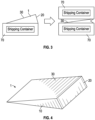
- the deflector 1 may have a one inch height when in an expanded configuration and have a collapsed height that is 0.5 inches or less, as shown in FIG. 3 .
- the deflector 1 may have a collapsed height of 0.4 inches or less.
- the deflector 1 may have a collapsed height that is more than 0.5 inches. It should be appreciated that the deflector 1 may have a height in an expanded configuration that is more than one inch. Because the deflector 1 may be attached to a flat surface or a non-flat surface, the base 10, side wall 20, top wall 30, and bonding complex 60 may be flexible to conform to a non-flat surface.
- the deflector 1 is installed on an intermodal container 70 by attaching the first adhesive 61 of the bonding complex 60 to the bottom surface 14 of the base 10.
- the top surface 63 of foam layer 62 may be attached to the first adhesive 61.
- the bottom surface 64 of foam layer 62 may be attached to the second adhesive 65.
- the second adhesive 65 may be attached to a top surface 72 of the intermodal container 70.
- the second adhesive 65 may be attached to a side surface 74AB of the intermodal container 70.
- the deflector 1 may reduce pressure drag on an intermodal container behind the deflector 1 by forcing airflow over a gap between.
- intermodal containers 70 transported without deflectors 1 may be impacted by pressure drag.
- the deflector 1 does not significantly increase downforce.
Landscapes
- Engineering & Computer Science (AREA)
- Mechanical Engineering (AREA)
- Standing Axle, Rod, Or Tube Structures Coupled By Welding, Adhesion, Or Deposition (AREA)
- Fittings On The Vehicle Exterior For Carrying Loads, And Devices For Holding Or Mounting Articles (AREA)
- Body Structure For Vehicles (AREA)
- Rigid Containers With Two Or More Constituent Elements (AREA)
- Details Of Rigid Or Semi-Rigid Containers (AREA)
- Aiming, Guidance, Guns With A Light Source, Armor, Camouflage, And Targets (AREA)
- Micro-Organisms Or Cultivation Processes Thereof (AREA)
- Vehicle Step Arrangements And Article Storage (AREA)
Description
- This application claims priority from
U.S. Application Number 62/845,271 filed on May 8, 2019 - The present disclosure relates to a deflector for use with railcars and containers. More particularly, it concerns a deflector that can be used to retrofit railcars to reduce aerodynamic drag.
- Intermodal shipping containers are ubiquitous in industry. Their large capacity and ability to stack on top of each other make them ideal for transporting large quantities of products. Unfortunately, the rectangular shape of the container, although useful for maximizing capacity and stacking capability, is not aerodynamically efficient. When transported by train, the gap in between the train cars causes much of this aerodynamic resistance. This inefficiency requires consumption of more fuel to move the container, leading to increased transport costs, increased pollution, reductions in train velocity, and other issues.
- Reducing the amount of drag produced by the shipping containers is no simple task. Redesigning the whole container would be costly and may require new infrastructure to accommodate the new container design; moreover, it may affect the container's capacity or stacking capabilities. Modifying an existing container presents similar challenges: piercing or welding the container may reduce the container's capacity or expose its contents to the environment. Installing a device or changing the shape of the top of the container may reduce, or altogether remove, the container's ability to stack. Furthermore, an installed device must be able to withstand the environmental conditions to which shipping containers are subjected, particularly wind, rain, and UV exposure. Installing a flexible device to cover the intercar gap on trains is generally impractical, as the gap allows for a wider turn radius and easier coupler access. Further, such a device would be cumbersome because cars are often switched between trains.
- Devices for drag reduction on trains are known for example from
DE 649 970 C andEP 2 236 381 A2 . - What is needed is a device that provides an effective way to reduce drag without sacrificing the container's ability to stack, reducing the container's capacity, or modifying the container's original design.
- This problem is solved by the features of
claim 1. Further embodiments are described in the dependent claims. - Various objects, features and advantages of this disclosure will become apparent from the following detailed description, which, taken in conjunction with the accompanying drawings, which depict, by way of illustration and example, certain embodiments of this deflector for intermodal containers and railcars.
- In order to describe the manner in which the advantages and features of the present inventive concept can be obtained, reference is made to embodiments thereof which are illustrated in the appended drawings. Understanding that these drawings depict only exemplary embodiments of the present inventive concept and are not, therefore, to be considered to be limiting of its scope, the principles herein are described and explained with additional specificity and detail through the use of the accompanying drawings in which:
-
FIGS. 1 A-C are perspective views of a deflector in accordance with the disclosure. -
FIG. 2 is a perspective view of the deflector shown in association with an intermodal container. -
FIG. 3 is a side view of the deflector shown in association with an intermodal container. -
FIG. 4 is a perspective view of the deflector. -
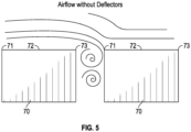
FIG. 5 is a side view of an intermodal container without a deflector. -
FIG. 6 is a side view of the deflector shown in association with an intermodal container. -
FIG. 7 is a perspective view of the deflector shown in association with an intermodal container. -
FIG. 8 is a perspective view of the deflector and the bonding complex shown in association with an intermodal container. - A deflector for use with railcars and intermodal containers according to the present disclosure is generally designated by the
reference numeral 1 and is shown inFIG. 1A in an exemplary installation on one type ofdeflector 1. Thedeflector 1 is depicted in an expanded configuration. The deflector disclosed herein provides benefit of deflecting air as railcars move. The deflector also provides the benefit of being collapsible, allowing for less expensive shipping. -
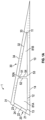
FIGS. 1-8 depict an embodiment of thedeflector 1. As shown inFIGS. 1A-C , the deflector has abase 10 that supports thedeflector 1. Thedeflector 1 also has asidewall 30 connected to thebase 10. Thedeflector 1 also has atop wall 30 connected to thebase 10 and the sidewall. In this regard, thebase 10,sidewall 20, andtop wall 30 are connected to one another to form a triangular prism that defines an internal volume 80. As shown inFIG. 1A , the internal volume 80 may be bisected by a divider 50 A-C to form afirst sub-internal volume 81A and asecond sub-internal volume 81B. Thedeflector 1 may have a first end 2 opposite a second end 3. - As shown in
FIGS. 1A-C , thebase 10 of thedeflector 1 has atop surface 12 and abottom surface 14 opposite thetop surface 12. Thetop surface 12 of thebase 10 faces the internal volume 80. Thebase 10 may have a rectangular shape. In this regard, thebase 10 may have afirst edge 11 opposite asecond edge 13. Thefirst edge 11 is configured to be attached to thetop wall 30. Thesecond edge 13 is configured to be attached to thesidewall 20. - The
base 10 has a width and a length. The width of thebase 10 may be one inch. As a non-limiting example, thebase 10 may have a width less or more than one inch. Thebase 10 may be rectangle. Thebase 10 may be other shapes such as square. Thebase 10 may be one inch thick. In another example, thebase 10 may be less than one inch thick. In another example, thebase 10 may be more than one inch thick. - As shown in
FIGS. 1A-C , thesidewall 20 of thedeflector 1 has aninner surface 22 and anouter surface 24 opposite theinner surface 22. Theinner surface 22 of thesidewall 20 faces the internal volume 80. Thesidewall 20 may have a rectangular shape. In this regard, thesidewall 20 may have afirst edge 21 opposite asecond edge 23. Thefirst edge 21 is configured to be attached to thebase 10. Thesecond edge 23 is configured to be attached to thetop wall 30. - The
sidewall 20 has a width and a length. The width of thesidewall 20 may be one inch. As a non-limiting example, thesidewall 20 may have a width less or more than one inch. Thesidewall 20 may be rectangle. Thesidewall 20 may be other shapes such as square. Thesidewall 20 may be curved. As an example, thesidewall 20 may be convex. As another example, thesidewall 20 may be concave. Thesidewall 20 may be one inch thick. In another example, thesidewall 20 may be less than one inch thick. In another example, thesidewall 20 may be more than one inch thick. Thedeflector 1 may be collapsible. In this regard, thesidewall 20 may be configured to collapse when a sufficient amount of weight is placed on thedeflector 1. As an example, as shown inFIG. 3 , when anintermodal container 70 is placed on top of thedeflector 1, thedeflector 1 may collapse. Because thesidewall 20 is collapsible, thesidewall 20 may have pleats similar to an accordion. In another example, thesidewall 20 may have a notch 29 or area that is less thick than the rest of thesidewall 20, providing a location where thesidewall 20 may fold inward or fold outward with respect to the sub-volume 81A. Similarly, thetop wall 30 may have a notch or area that is less thick than the rest of thetop wall 30, providing a location where thetop wall 30 may fold inward with respect to the internal sub-volumes 81 A-C. It should be appreciated that any of thebase 10,sidewall 20,top wall 30, or the dividers 50 A-C may have a notch or area that is less thick than the rest of thebase 10,sidewall 20,top wall 30, or the dividers 50 A-C, providing a location where thebase 10,sidewall 20,top wall 30, or the dividers 50 A-C may fold inward or outward with respect to the internal sub-volumes 81 A-C. In some examples, thedeflector 1 may be used with railcars or intermodal containers that are not stacked. In such examples, thedeflector 1 may not be collapsible. In non-collapsible examples, thedeflector 1, may be formed from a hard plastic. - As shown in
FIGS. 1A-C , thetop wall 30 of thedeflector 1 has aninner surface 32 and anouter surface 34 opposite theinner surface 32. Theinner surface 32 of thetop wall 30 faces the internal volume 80. Thetop wall 30 may have a rectangular shape. In this regard, thetop wall 30 may have afirst edge 31 opposite asecond edge 33. Thefirst edge 31 is configured to be attached to thesidewall 20. Thesecond edge 33 is configured to be attached to thebase 10. - The
top wall 30 has a width and a length. The width of thetop wall 30 may be one inch. As a non-limiting example, thetop wall 30 may have a width less or more than one inch. As shown, inFIG. 3 , thetop wall 30 may be rectangle. Thetop wall 30 may be other shapes such as square. Thetop wall 30 may be curved. As an example, thetop wall 30 may be convex. As another example, thetop wall 30 may be concave. Thetop wall 30 may be one inch thick. In another example, thetop wall 30 may be less than one inch thick. In another example, thetop wall 30 may be more than one inch thick. - The
base 10, side wall, andtop wall 30 are connected to one another. Thesecond edge 13 of thebase 10 is connected to thefirst edge 21 of thesidewall 20. Thesecond edge 23 of thesidewall 20 is connected to thefirst edge 31 of thetop wall 30. Thesecond edge 33 of thetop wall 30 is connected to thefirst edge 11 of thebase 10. In this regard, thebase 10,sidewall 20, andtop wall 30 are connected to one another to form a triangular prism. The edges that are connected to one another may be permanently attached to one another. In another example, the edges may also be removably attached to one another. One of skill in the art will appreciate that thedeflector 1 may have more than three walls to form other shapes such as cube, rectangular prism, or any other shape known in the art. - As shown in
FIG. 1A , thedivider 50A bisecting the internal volume 80 has afirst side surface 52 opposite asecond side 54. The divider has astop edge 51 and abottom edge 53 opposite thetop edge 51. Thetop edge 51 is attached to the inner surface of thetop wall 30. Thebottom edge 53 of the divider is connected to thetop surface 12 of thebase 10. In this regard, thedivider 50 A divides the internal volume 80 into afirst sub volume 81A and asecond sub volume 81B. It should be appreciated that, as shown inFIGS. 1 B-C , thedeflector 1 may have more than one divider 50 A-C. It should also be appreciated that, as shown inFIG. 1B , thedeflector 1 may have more than one sub-volume 81 A-C. Each of the sub-volumes 81 A-C may be hollow. In some examples, one or all of the sub-volumes may be filled with a suitable material. The suitable material used for filing the sub-volumes 81 A-C may be the same material as thebase 10,sidewall 20, andtop wall 30. The sub-volumes 81 AB may also be filled with a material that is different from the material used to form thebase 10,sidewall 20, andtop wall 30. In some examples, each sub-volume 81 A-C is filled with the same material. In other examples, each sub-volume 81 A-C is filled with a different material from the other sub-volumes 81 A-C. In some examples, each sub-volume 81 A-C is filled. In other examples, at least one sub-volume 81 A-C is filled and the other sub-volumes 81 A-C are not filled. As shown inFIG. 1A , thedivider 50 A is perpendicular to thebase 10. In another example, as shown inFIGS. 1B-1C , the divider 50 A-C may be slanted or non-perpendicular in relation to thebase 10. - As shown in
FIGS. 7 and8 , one or both of the first end 2 or the second end 3 may be sealed or closed. This may assist in reducing pressure drag on theintermodal container 70. As shown inFIG. 1 , the one or both of the first end 2 or the second end 3 of thedeflector 1 may be open. In some examples, one or both of the first end 2 or the second end 3 may be tapered. - As shown in
FIG. 8 , thedeflector 1 may include abonding complex 60. Thebonding complex 60 may have a firstadhesive layer 61 and a secondadhesive layer 65. Thebonding complex 60 may also include afoam layer 62. Thefoam layer 62 may have atop foam surface 63 and abottom foam surface 64 opposite the top foam surface. The first adhesive may be applied to thetop foam surface 64. Thefoam layer 62 may provide added durability to thedeflector 1 when thedeflector 1 is attached to an intermodal container. The second adhesive may be applied to thebottom foam surface 65. Thebonding complex 60 may be used to attach thedeflector 1 to a surface of anintermodal container 70. - As shown in
FIGS. 2 ,3 ,6 , and7 , thebonding complex 60 may be used to attach thedeflector 1 to thetop surface 72 of anintermodal container 70. As shown, thedeflector 1 may be attached to thetop surface 72 of anintermodal container 70 near thefist end 71 or thesecond end 73 of theintermodal container 70. In some examples, thedeflector 1 may be attached to one or more side surface 74AB of theintermodal container 70. In another example, more than onedeflector 1 may be attached to theintermodal container 70. It should be appreciated that thedeflector 1 may be used to reduce pressure drag on any type of railway vehicle known in the art, including, but not limited to passenger railcars, freight containers, ancillary vehicles, military railway vehicles, and maintenance vehicles. It should also be appreciated that thedeflector 1 may be used on any type of freight container, including, but not limited, to container railway vehicles, bulk freight railway vehicles, specialist use railway vehicles, and multi-modal railway vehicles. The multi-modal vehicles may include, but are not limited to, roadrailer, modalohr road trailer carriers, well car, and intermodal cars such as bulk freezing containers, flat rack containers, insulated containers, refrigerated containers, open top containers, custom containers, and any other container known in the art. It should also be appreciated that thedeflector 1 may be used for decreasing pressure drag on containers transported by other means such as by road or by sea. - Because the
deflector 1 may be used to retrofit anintermodal container 70, thedeflector 1 may have a length appropriate to extend almost the entire width of theintermodal container 70. As an example, thedeflector 1 may have a length up to 9 feet. An advantage of thedeflector 1 is the ability to collapse or deform under a sufficient weight and return to the original shape once the weight is removed. As shown inFIG. 2 , thedeflector 1 may be used with stackable intermodal containers. When stackableintermodal containers 70 are stacked there may be a gap between the intermodal containers. Thedeflector 1 is configured to collapse to a height small enough to fit between stackedintermodal containers 70 without damaging thedeflector 1 or theintermodal container 70. In this regard, thedeflector 1 may have a one inch height when in an expanded configuration and have a collapsed height that is 0.5 inches or less, as shown inFIG. 3 . In some examples, thedeflector 1 may have a collapsed height of 0.4 inches or less. In other examples, thedeflector 1 may have a collapsed height that is more than 0.5 inches. It should be appreciated that thedeflector 1 may have a height in an expanded configuration that is more than one inch. Because thedeflector 1 may be attached to a flat surface or a non-flat surface, thebase 10,side wall 20,top wall 30, and bonding complex 60 may be flexible to conform to a non-flat surface. - In use, the
deflector 1 is installed on anintermodal container 70 by attaching thefirst adhesive 61 of thebonding complex 60 to thebottom surface 14 of thebase 10. Thetop surface 63 offoam layer 62 may be attached to thefirst adhesive 61. Thebottom surface 64 offoam layer 62 may be attached to thesecond adhesive 65. The second adhesive 65 may be attached to atop surface 72 of theintermodal container 70. In another example, the second adhesive 65 may be attached to a side surface 74AB of theintermodal container 70. As shown inFIG. 6 , once thedeflector 1 is attached to theintermodal container 70, thedeflector 1 may reduce pressure drag on an intermodal container behind thedeflector 1 by forcing airflow over a gap between. As shown inFIG. 5 ,intermodal containers 70 transported withoutdeflectors 1 may be impacted by pressure drag. Thedeflector 1 does not significantly increase downforce. - While the present disclosure has been described with reference to various embodiments, it will be understood that these embodiments are illustrative and that the scope of the disclosure is not limited to them. Those skilled in the art will appreciate that variations from the specific embodiments disclosed above are contemplated by the invention. Many variations, modifications, additions, and improvements are possible. More generally, embodiments in accordance with the present disclosure have been described in the context of particular implementations. Functionality may be separated or combined in blocks differently in various embodiments of the disclosure or described with different terminology. These and other variations, modifications, additions, and improvements may fall within the scope of the disclosure as defined in the claims that follow.
Claims (18)
- A deflector (1) comprising:a first end;a second end;a top wall (30);a base (10) comprising: a top surface (12) and a bottom surface (14), the bottom surface configured to be attached to a surface (72) of a railway vehicle (70);a sidewall (20) comprising: an inner surface (22) and an outer surface (24) opposite the inner surface,characterized in that the sidewall is collapsible and the top wall (30) is connected to the base (10) and the sidewall (20) to form a triangular prism shape.
- The deflector of claim 1, wherein the base (10) is connected to the sidewall (20) to form an internal volume (80).
- The deflector of claim 2, further comprising a divider (50 A-C), wherein the divider bisects the internal volume (80).
- The deflector of claim 1, wherein at least one of the base (10), the top wall (30), and the sidewall (20) is formed from a continuous material.
- The deflector of claim 1, further comprising a bonding complex (60), the bonding complex comprising an adhesive layer (61).
- The deflector of claim 5, wherein the bonding complex (60) further comprises a foam layer (62).
- The deflector of claim 1, wherein at least one of the top wall (30) and the sidewall (20) is curved.
- The deflector of claim 1, wherein the deflector (1) is formed from a shape memory material comprising ethylene propylene diene rubber.
- The deflector of claim 3, wherein the top wall (30), the base (10), the sidewall (20), and the divider (50) are removably attached to one another.
- The deflector of claim 5, wherein the adhesive complex (60) is permanent, wherein the deflector (1) is configured to be permanently attached to the surface of the railway vehicle.
- The deflector of claim 5, wherein the adhesive complex (60) is temporary, wherein the deflector is configured to be temporarily attached to the surface of the railway vehicle.
- The deflector of claim 1, wherein at least a portion of the first end and the second end are unsealed.
- The deflector of claim 1, wherein the first end and the second end are sealed.
- The deflector of claim 1, the deflector further comprising:a divider (50), wherein the divider has a top edge (51) and a bottom edge (53), wherein the top edge is attached to an inner surface (32) of the top wall (30) and the bottom edge is attached to the top surface (12) of the base (10);wherein at least a portion of the first end is unsealed;wherein at least a portion of the second end is unsealed; anda bonding complex (60) configured to permanently bond the deflector to the top surface of the railway vehicle, the bonding complex comprising a first adhesive layer (61), a second adhesive layer (65), a top foam surface (63), and a bottom foam surface (64) opposite the top foam surface, the first adhesive layer applied to the top foam surface and the second adhesive layer applied to the bottom foam surface;wherein the inner surface of the top wall (30), the inner surface of the sidewall (20), and the top surface of the base (10) define an internal volume (80),wherein the divider (50) bisects the internal volume,wherein the deflector (1) is formed from a shape memory material comprising ethylene propylene diene rubber,wherein the deflector is collapsible when a sufficient weight is placed on the deflector, andwherein the deflector returns to an expanded configuration when the sufficient weight is removed from the deflector.
- A method of reducing pressure drag, the method comprising:providing a deflector (1), the deflector comprising:a base (10) comprising: a top surface (12) and a bottom surface (14), the bottom surface configured to be attached to a surface of a railway vehicle; a sidewall (20) comprising: an inner surface (22) and an outer surface (24) opposite the inner surface, wherein the sidewall is collapsible;a top wall (30) comprising an inner surface (32) and an outer surface (34);a divider (50);a first end, wherein at least a portion of the first end is unsealed;a second end, wherein at least a portion of the second end is unsealed; anda bonding complex (60) configured to permanently bond the deflector to the surface of the railway vehicle, the bonding complex comprising a first adhesive layer (61), a second adhesive layer (65), a top foam surface (63), and a bottom foam surface (64) opposite the top foam surface, the first adhesive layer applied to the top foam surface and the second adhesive layer applied to the bottom foam surface;attaching the deflector to the surface (72) of the railway vehicle (70) by attaching the bonding complex (60) to the surface of the railway vehicle.wherein the top wall (30), the base (10), and the sidewall (20) are connected to form a triangular prism shape,wherein the inner surface of the top wall, the inner surface of the sidewall, and the top surface of the base define an internal volume (80), wherein the divider (50) bisects the internal volume, andwherein the deflector (1) is formed from a shape memory material comprising ethylene propylene diene rubber, and
- The method of claim 15, wherein the deflector is attached to a top surface (72) of the railway vehicle.
- The deflector of claim 1, further comprising a bonding complex (60) configured to permanently bond the deflector to the surface of the railway vehicle (72), the bonding complex comprising a first adhesive layer (61), a second adhesive layer (65), a top foam surface (63), and a bottom foam surface (64) opposite the top foam surface, the first adhesive layer applied to the top foam surface and the second adhesive layer applied to the bottom foam surface.
- An intermodal container (70) on a railway vehicle, a top surface (72) of the vehicle having a deflector (1) according to any one of claims 1 to 14 and 17 permanently bonded thereto.
Applications Claiming Priority (2)
| Application Number | Priority Date | Filing Date | Title |
|---|---|---|---|
| US201962845271P | 2019-05-08 | 2019-05-08 | |
| PCT/US2019/067601 WO2020226698A1 (en) | 2019-05-08 | 2019-12-19 | Deflector for vehicle |
Publications (4)
| Publication Number | Publication Date |
|---|---|
| EP3966088A1 EP3966088A1 (en) | 2022-03-16 |
| EP3966088A4 EP3966088A4 (en) | 2023-02-01 |
| EP3966088C0 EP3966088C0 (en) | 2024-03-06 |
| EP3966088B1 true EP3966088B1 (en) | 2024-03-06 |
Family
ID=73047806
Family Applications (1)
| Application Number | Title | Priority Date | Filing Date |
|---|---|---|---|
| EP19928174.2A Active EP3966088B1 (en) | 2019-05-08 | 2019-12-19 | Deflector for vehicle |
Country Status (11)
| Country | Link |
|---|---|
| US (2) | US11459000B2 (en) |
| EP (1) | EP3966088B1 (en) |
| JP (1) | JP7402895B2 (en) |
| CN (1) | CN113840772B (en) |
| AR (1) | AR118860A1 (en) |
| AU (1) | AU2019444491B2 (en) |
| CA (1) | CA3139306C (en) |
| MX (1) | MX2021013559A (en) |
| UA (1) | UA128901C2 (en) |
| WO (1) | WO2020226698A1 (en) |
| ZA (1) | ZA202107585B (en) |
Families Citing this family (2)
| Publication number | Priority date | Publication date | Assignee | Title |
|---|---|---|---|---|
| CA3139306C (en) * | 2019-05-08 | 2024-05-28 | Deflect LLC | Deflector for vehicle |
| EP4545373A1 (en) * | 2023-10-23 | 2025-04-30 | SpeedInnov | Railway vehicle comprising an air deflection system at a longitudinal extremity of a car roof facing another car |
Family Cites Families (52)
| Publication number | Priority date | Publication date | Assignee | Title |
|---|---|---|---|---|
| US2243906A (en) | 1933-12-19 | 1941-06-03 | Huet Andre | Apparatus for shielding a body from fluid currents |
| DE640970C (en) * | 1935-01-19 | 1937-01-16 | Deutsche Reichsbahn | Streamlined design of the front surfaces of couplable railway vehicles |
| US3768854A (en) * | 1971-10-26 | 1973-10-30 | D Johnson | Wind deflector for a towed trailer |
| US3904236A (en) | 1974-08-19 | 1975-09-09 | Camper Flow Mfg Co | Wind deflector for a towed trailer |
| US3934922A (en) * | 1974-09-05 | 1976-01-27 | Aerovironment Inc. | Aerodynamic drag reduction devices for surface vehicles |
| US4082340A (en) * | 1976-08-03 | 1978-04-04 | Alexander Taylor | Air current deflecting device |
| US4084846A (en) * | 1976-08-20 | 1978-04-18 | Rudkin-Wiley Corporation | Universal support assembly for drag reducing equipment |
| US4141580A (en) * | 1977-07-07 | 1979-02-27 | Ivan Joseph R | Collapsible wind deflector |
| US4153288A (en) * | 1977-09-26 | 1979-05-08 | Donna M. Mueller | Folding air deflector |
| US4153129A (en) * | 1977-11-11 | 1979-05-08 | Deflecta-Shield Corp. | Air current deflector shield for vehicles |
| JPS5774816U (en) * | 1980-10-28 | 1982-05-08 | ||
| US4509786A (en) * | 1982-11-08 | 1985-04-09 | General Motors Corporation | Support for collapsible drag reducer |
| US4462628A (en) * | 1982-11-08 | 1984-07-31 | General Motors Corporation | Guide for collapsible drag reducer |
| US4738203A (en) | 1984-02-27 | 1988-04-19 | Pullman Standard, Inc. | Aerodynamically structured railway car with corner, air flow guides |
| US4569289A (en) | 1984-02-27 | 1986-02-11 | Pullman Standard Inc. | Air flow guide structure for open top railway car |
| US4756256A (en) | 1986-07-30 | 1988-07-12 | Gunderson, Inc. | Aerodynamic drag reduction for railcars |
| US4863213A (en) * | 1987-11-17 | 1989-09-05 | Deaver Dann T | Aerodynamic spoiler for a pickup truck and a method for providing a generally common construction for a variety of pickup trucks |
| US4858988A (en) * | 1988-04-19 | 1989-08-22 | Donnelly Corporation | Vehicular window assembly |
| AU3605189A (en) | 1988-06-08 | 1989-12-14 | Technisearch Limited | Device for reducing aerodynamic drag on surface vehicles |
| US5039156A (en) | 1989-06-13 | 1991-08-13 | Covercraft Industries, Inc. | Automobile hood shield with deflector |
| US5280990A (en) | 1991-10-08 | 1994-01-25 | Rinard Gordon L | Vehicle drag reduction system |
| US5403059A (en) * | 1993-02-23 | 1995-04-04 | G.T. Styling, Inc. | Vehicle hood shield and method of mounting thereof |
| FR2717760B1 (en) | 1994-03-24 | 1996-04-26 | Gec Alsthom Transport Sa | Device for reducing the aerodynamic drag of a cavity in a flow and vehicle, in particular rail, comprising such a device. |
| US5513894A (en) | 1995-01-24 | 1996-05-07 | Ragsdale; Grady S. | Rigid air-deflecting tank contoured to tow-vehicle roof |
| US6224141B1 (en) * | 1999-07-01 | 2001-05-01 | Steve A. Brodlo | Trailer side wind deflecting system |
| US6669270B1 (en) * | 2002-09-05 | 2003-12-30 | Loyd Ray Card | Truck wind deflector |
| DE102006012644B4 (en) * | 2005-12-30 | 2007-11-29 | Webasto Ag | Wind deflector in the automotive sector |
| US20100194144A1 (en) | 2007-08-01 | 2010-08-05 | Sinha Sumon K | Deturbulator fuel economy enhancement for trucks |
| NL1034363C2 (en) * | 2007-08-13 | 2009-02-16 | Gandert Marcel Rita Van Raemdonck | Flow conductor for use in aerodynamic device for vehicle e.g. lorry, has thickened portions formed in front edge, and streamlined outer contours in cross section that is transverse to front edge |
| US8382194B2 (en) | 2008-03-21 | 2013-02-26 | Richard M. Wood | Outboard wake stabilization device and method for reducing the aerodynamic drag of ground vehicles |
| US20110115254A1 (en) | 2009-03-05 | 2011-05-19 | Joseph Skopic | Apparatus for reducing drag on vehicles with planar rear surfaces |
| JP2010228559A (en) * | 2009-03-26 | 2010-10-14 | Railway Technical Res Inst | Airflow separation control structure for moving objects |
| DE202009004545U1 (en) * | 2009-04-01 | 2009-07-23 | Hübner GmbH | Wind deflector for mounting substantially flush with the outer skin in the region of the transition between two articulated vehicles |
| JP3153585U (en) * | 2009-06-30 | 2009-09-10 | 秋夫 其田 | Air resistance reduction device for truck bed |
| US9937963B2 (en) | 2009-08-04 | 2018-04-10 | Eric Sandgren | Automated drag reduction in moving objects |
| CN101659262A (en) | 2009-09-24 | 2010-03-03 | 唐山轨道客车有限责任公司 | Device for reducing drag between high-speed multiple unit trains |
| JP5016660B2 (en) * | 2009-11-26 | 2012-09-05 | 株式会社ホンダアクセス | Vehicle spoiler mounting structure |
| US8651554B1 (en) * | 2010-02-26 | 2014-02-18 | Lund, Inc. | Vehicle shield |
| JP2012148687A (en) * | 2011-01-19 | 2012-08-09 | Railway Technical Research Institute | Air flow separation suppression structure of moving body |
| KR20120006077U (en) * | 2011-02-22 | 2012-08-30 | 박종표 | Rear Spoiler |
| CN102951166B (en) * | 2011-08-23 | 2016-01-20 | 北京航空航天大学 | Based on the chassis of vehicle body of high speed railway with the aerodynamic force aerotrain of imitative wing |
| EP2626281B1 (en) * | 2012-02-09 | 2016-06-08 | Scania CV AB (publ) | An air guiding device and a method of reducing the air resistance of a ground vehicle |
| WO2013172914A2 (en) | 2012-02-27 | 2013-11-21 | Sinhatech | Self adjusting deturbulator enhanced flap and wind deflector |
| US8506004B1 (en) | 2012-07-30 | 2013-08-13 | Praxair Technology, Inc. | Gap fairing and drag reduction method |
| US9550535B2 (en) | 2015-04-17 | 2017-01-24 | General Electric Company | Aerodynamic control system and method |
| CN205524530U (en) * | 2016-05-05 | 2016-08-31 | 栾晓亮 | A kuppe that is used for outer top surface of trailer driver's cabin |
| CN106976486A (en) * | 2017-04-11 | 2017-07-25 | 安徽科瑞特模塑有限公司 | A kind of adjustable truck kuppe |
| US10065482B1 (en) * | 2017-04-19 | 2018-09-04 | Ford Global Technologies, Llc | Vehicle flow influencing assembly and method |
| DE102017113761A1 (en) * | 2017-06-21 | 2018-12-27 | HÜBNER GmbH & Co. KG | Wind deflector for arrangement between two vehicle parts of a rail vehicle |
| CN107792109A (en) * | 2017-09-26 | 2018-03-13 | 中车工业研究院有限公司 | Chassis of rail vehicle and rail vehicle |
| CN109677432A (en) * | 2019-02-15 | 2019-04-26 | 闫志立 | A kind of safety high speed train |
| CA3139306C (en) * | 2019-05-08 | 2024-05-28 | Deflect LLC | Deflector for vehicle |
-
2019
- 2019-12-19 CA CA3139306A patent/CA3139306C/en active Active
- 2019-12-19 EP EP19928174.2A patent/EP3966088B1/en active Active
- 2019-12-19 MX MX2021013559A patent/MX2021013559A/en unknown
- 2019-12-19 JP JP2021565831A patent/JP7402895B2/en active Active
- 2019-12-19 AU AU2019444491A patent/AU2019444491B2/en active Active
- 2019-12-19 UA UAA202106899A patent/UA128901C2/en unknown
- 2019-12-19 US US16/721,009 patent/US11459000B2/en active Active
- 2019-12-19 WO PCT/US2019/067601 patent/WO2020226698A1/en not_active Ceased
- 2019-12-19 CN CN201980096155.0A patent/CN113840772B/en active Active
-
2020
- 2020-05-05 AR ARP200101270A patent/AR118860A1/en active IP Right Grant
-
2021
- 2021-05-12 US US17/318,283 patent/US11613280B2/en active Active
- 2021-10-08 ZA ZA2021/07585A patent/ZA202107585B/en unknown
Also Published As
| Publication number | Publication date |
|---|---|
| EP3966088C0 (en) | 2024-03-06 |
| US20200353957A1 (en) | 2020-11-12 |
| JP7402895B2 (en) | 2023-12-21 |
| EP3966088A1 (en) | 2022-03-16 |
| US11459000B2 (en) | 2022-10-04 |
| MX2021013559A (en) | 2021-12-10 |
| AR118860A1 (en) | 2021-11-03 |
| UA128901C2 (en) | 2024-11-20 |
| ZA202107585B (en) | 2024-11-27 |
| JP2022531870A (en) | 2022-07-12 |
| CN113840772A (en) | 2021-12-24 |
| CA3139306A1 (en) | 2020-11-12 |
| AU2019444491A1 (en) | 2021-11-04 |
| AU2019444491B2 (en) | 2023-05-11 |
| CN113840772B (en) | 2024-04-12 |
| AU2019444491A8 (en) | 2021-11-18 |
| EP3966088A4 (en) | 2023-02-01 |
| WO2020226698A1 (en) | 2020-11-12 |
| US11613280B2 (en) | 2023-03-28 |
| CA3139306C (en) | 2024-05-28 |
| US20210261173A1 (en) | 2021-08-26 |
Similar Documents
| Publication | Publication Date | Title |
|---|---|---|
| US11613280B2 (en) | Deflector for vehicle | |
| US9283996B2 (en) | Airflow baffle for commerical truck fuel efficiency improvements | |
| US4057280A (en) | Aerodynamic drag reduction devices for surface vehicles | |
| US10059385B1 (en) | Aerodynamic fairings for cargo enclosures | |
| EP3759010B1 (en) | Trailer fairing and system for improved aerodynamic performance | |
| US10273070B2 (en) | Collapsible container | |
| CN1215007A (en) | Corner bumper for use on movable and fixed objects | |
| CA3026579C (en) | Container for transport of bulk liquids using dry trailers | |
| EP1712492B1 (en) | Foldable shipping container bulkhead | |
| US8534203B2 (en) | Support system for a railcar and method for assembling the same | |
| US6945404B2 (en) | Single piece organizer | |
| US6517140B2 (en) | Pickup truck tailgate wind deflector | |
| CN104284825B (en) | Transport container, vehicle, towing group, method for loading a transport container, and method for transporting bulk materials | |
| CA2078711A1 (en) | Interlocking carton and lid | |
| JP2010506776A (en) | Ships and related assembly and control laws | |
| CA2827931A1 (en) | Method and system for aerodynamic enhancement of intermodal transportation | |
| CN220997620U (en) | A cushioning packaging box structure | |
| CN100572202C (en) | Single-piece packing plate capable of being folded into box bodies with various sizes | |
| EP3967580B1 (en) | Vortex drag disruption apparatus | |
| JP2006183365A (en) | Vehicular shock absorber | |
| WO2012097387A1 (en) | Flat bed truck |
Legal Events
| Date | Code | Title | Description |
|---|---|---|---|
| STAA | Information on the status of an ep patent application or granted ep patent |
Free format text: STATUS: THE INTERNATIONAL PUBLICATION HAS BEEN MADE |
|
| PUAI | Public reference made under article 153(3) epc to a published international application that has entered the european phase |
Free format text: ORIGINAL CODE: 0009012 |
|
| STAA | Information on the status of an ep patent application or granted ep patent |
Free format text: STATUS: REQUEST FOR EXAMINATION WAS MADE |
|
| 17P | Request for examination filed |
Effective date: 20211006 |
|
| AK | Designated contracting states |
Kind code of ref document: A1 Designated state(s): AL AT BE BG CH CY CZ DE DK EE ES FI FR GB GR HR HU IE IS IT LI LT LU LV MC MK MT NL NO PL PT RO RS SE SI SK SM TR |
|
| DAV | Request for validation of the european patent (deleted) | ||
| DAX | Request for extension of the european patent (deleted) | ||
| REG | Reference to a national code |
Ref country code: DE Ref legal event code: R079 Free format text: PREVIOUS MAIN CLASS: B62D0035000000 Ipc: B61D0017020000 Ref country code: DE Ref legal event code: R079 Ref document number: 602019048037 Country of ref document: DE Free format text: PREVIOUS MAIN CLASS: B62D0035000000 Ipc: B61D0017020000 |
|
| A4 | Supplementary search report drawn up and despatched |
Effective date: 20230105 |
|
| RIC1 | Information provided on ipc code assigned before grant |
Ipc: B60P 3/36 20060101ALI20221223BHEP Ipc: B60J 1/20 20060101ALI20221223BHEP Ipc: B62D 35/00 20060101ALI20221223BHEP Ipc: B61D 17/02 20060101AFI20221223BHEP |
|
| STAA | Information on the status of an ep patent application or granted ep patent |
Free format text: STATUS: EXAMINATION IS IN PROGRESS |
|
| 17Q | First examination report despatched |
Effective date: 20230621 |
|
| GRAP | Despatch of communication of intention to grant a patent |
Free format text: ORIGINAL CODE: EPIDOSNIGR1 |
|
| STAA | Information on the status of an ep patent application or granted ep patent |
Free format text: STATUS: GRANT OF PATENT IS INTENDED |
|
| INTG | Intention to grant announced |
Effective date: 20231005 |
|
| GRAJ | Information related to disapproval of communication of intention to grant by the applicant or resumption of examination proceedings by the epo deleted |
Free format text: ORIGINAL CODE: EPIDOSDIGR1 |
|
| STAA | Information on the status of an ep patent application or granted ep patent |
Free format text: STATUS: EXAMINATION IS IN PROGRESS |
|
| GRAP | Despatch of communication of intention to grant a patent |
Free format text: ORIGINAL CODE: EPIDOSNIGR1 |
|
| STAA | Information on the status of an ep patent application or granted ep patent |
Free format text: STATUS: GRANT OF PATENT IS INTENDED |
|
| INTC | Intention to grant announced (deleted) | ||
| GRAS | Grant fee paid |
Free format text: ORIGINAL CODE: EPIDOSNIGR3 |
|
| INTG | Intention to grant announced |
Effective date: 20240104 |
|
| GRAA | (expected) grant |
Free format text: ORIGINAL CODE: 0009210 |
|
| STAA | Information on the status of an ep patent application or granted ep patent |
Free format text: STATUS: THE PATENT HAS BEEN GRANTED |
|
| AK | Designated contracting states |
Kind code of ref document: B1 Designated state(s): AL AT BE BG CH CY CZ DE DK EE ES FI FR GB GR HR HU IE IS IT LI LT LU LV MC MK MT NL NO PL PT RO RS SE SI SK SM TR |
|
| REG | Reference to a national code |
Ref country code: CH Ref legal event code: EP |
|
| REG | Reference to a national code |
Ref country code: IE Ref legal event code: FG4D |
|
| REG | Reference to a national code |
Ref country code: DE Ref legal event code: R096 Ref document number: 602019048037 Country of ref document: DE |
|
| U01 | Request for unitary effect filed |
Effective date: 20240321 |
|
| U07 | Unitary effect registered |
Designated state(s): AT BE BG DE DK EE FI FR IT LT LU LV MT NL PT SE SI Effective date: 20240402 |
|
| PG25 | Lapsed in a contracting state [announced via postgrant information from national office to epo] |
Ref country code: GR Free format text: LAPSE BECAUSE OF FAILURE TO SUBMIT A TRANSLATION OF THE DESCRIPTION OR TO PAY THE FEE WITHIN THE PRESCRIBED TIME-LIMIT Effective date: 20240607 |
|
| PG25 | Lapsed in a contracting state [announced via postgrant information from national office to epo] |
Ref country code: HR Free format text: LAPSE BECAUSE OF FAILURE TO SUBMIT A TRANSLATION OF THE DESCRIPTION OR TO PAY THE FEE WITHIN THE PRESCRIBED TIME-LIMIT Effective date: 20240306 Ref country code: RS Free format text: LAPSE BECAUSE OF FAILURE TO SUBMIT A TRANSLATION OF THE DESCRIPTION OR TO PAY THE FEE WITHIN THE PRESCRIBED TIME-LIMIT Effective date: 20240606 |
|
| PG25 | Lapsed in a contracting state [announced via postgrant information from national office to epo] |
Ref country code: ES Free format text: LAPSE BECAUSE OF FAILURE TO SUBMIT A TRANSLATION OF THE DESCRIPTION OR TO PAY THE FEE WITHIN THE PRESCRIBED TIME-LIMIT Effective date: 20240306 |
|
| PG25 | Lapsed in a contracting state [announced via postgrant information from national office to epo] |
Ref country code: RS Free format text: LAPSE BECAUSE OF FAILURE TO SUBMIT A TRANSLATION OF THE DESCRIPTION OR TO PAY THE FEE WITHIN THE PRESCRIBED TIME-LIMIT Effective date: 20240606 Ref country code: NO Free format text: LAPSE BECAUSE OF FAILURE TO SUBMIT A TRANSLATION OF THE DESCRIPTION OR TO PAY THE FEE WITHIN THE PRESCRIBED TIME-LIMIT Effective date: 20240606 Ref country code: HR Free format text: LAPSE BECAUSE OF FAILURE TO SUBMIT A TRANSLATION OF THE DESCRIPTION OR TO PAY THE FEE WITHIN THE PRESCRIBED TIME-LIMIT Effective date: 20240306 Ref country code: GR Free format text: LAPSE BECAUSE OF FAILURE TO SUBMIT A TRANSLATION OF THE DESCRIPTION OR TO PAY THE FEE WITHIN THE PRESCRIBED TIME-LIMIT Effective date: 20240607 Ref country code: ES Free format text: LAPSE BECAUSE OF FAILURE TO SUBMIT A TRANSLATION OF THE DESCRIPTION OR TO PAY THE FEE WITHIN THE PRESCRIBED TIME-LIMIT Effective date: 20240306 |
|
| PG25 | Lapsed in a contracting state [announced via postgrant information from national office to epo] |
Ref country code: IS Free format text: LAPSE BECAUSE OF FAILURE TO SUBMIT A TRANSLATION OF THE DESCRIPTION OR TO PAY THE FEE WITHIN THE PRESCRIBED TIME-LIMIT Effective date: 20240706 |
|
| PG25 | Lapsed in a contracting state [announced via postgrant information from national office to epo] |
Ref country code: SM Free format text: LAPSE BECAUSE OF FAILURE TO SUBMIT A TRANSLATION OF THE DESCRIPTION OR TO PAY THE FEE WITHIN THE PRESCRIBED TIME-LIMIT Effective date: 20240306 |
|
| PG25 | Lapsed in a contracting state [announced via postgrant information from national office to epo] |
Ref country code: CZ Free format text: LAPSE BECAUSE OF FAILURE TO SUBMIT A TRANSLATION OF THE DESCRIPTION OR TO PAY THE FEE WITHIN THE PRESCRIBED TIME-LIMIT Effective date: 20240306 |
|
| PG25 | Lapsed in a contracting state [announced via postgrant information from national office to epo] |
Ref country code: PL Free format text: LAPSE BECAUSE OF FAILURE TO SUBMIT A TRANSLATION OF THE DESCRIPTION OR TO PAY THE FEE WITHIN THE PRESCRIBED TIME-LIMIT Effective date: 20240306 |
|
| PG25 | Lapsed in a contracting state [announced via postgrant information from national office to epo] |
Ref country code: SK Free format text: LAPSE BECAUSE OF FAILURE TO SUBMIT A TRANSLATION OF THE DESCRIPTION OR TO PAY THE FEE WITHIN THE PRESCRIBED TIME-LIMIT Effective date: 20240306 |
|
| PG25 | Lapsed in a contracting state [announced via postgrant information from national office to epo] |
Ref country code: SM Free format text: LAPSE BECAUSE OF FAILURE TO SUBMIT A TRANSLATION OF THE DESCRIPTION OR TO PAY THE FEE WITHIN THE PRESCRIBED TIME-LIMIT Effective date: 20240306 Ref country code: SK Free format text: LAPSE BECAUSE OF FAILURE TO SUBMIT A TRANSLATION OF THE DESCRIPTION OR TO PAY THE FEE WITHIN THE PRESCRIBED TIME-LIMIT Effective date: 20240306 Ref country code: RO Free format text: LAPSE BECAUSE OF FAILURE TO SUBMIT A TRANSLATION OF THE DESCRIPTION OR TO PAY THE FEE WITHIN THE PRESCRIBED TIME-LIMIT Effective date: 20240306 Ref country code: PL Free format text: LAPSE BECAUSE OF FAILURE TO SUBMIT A TRANSLATION OF THE DESCRIPTION OR TO PAY THE FEE WITHIN THE PRESCRIBED TIME-LIMIT Effective date: 20240306 Ref country code: IS Free format text: LAPSE BECAUSE OF FAILURE TO SUBMIT A TRANSLATION OF THE DESCRIPTION OR TO PAY THE FEE WITHIN THE PRESCRIBED TIME-LIMIT Effective date: 20240706 Ref country code: CZ Free format text: LAPSE BECAUSE OF FAILURE TO SUBMIT A TRANSLATION OF THE DESCRIPTION OR TO PAY THE FEE WITHIN THE PRESCRIBED TIME-LIMIT Effective date: 20240306 |
|
| REG | Reference to a national code |
Ref country code: DE Ref legal event code: R097 Ref document number: 602019048037 Country of ref document: DE |
|
| U20 | Renewal fee for the european patent with unitary effect paid |
Year of fee payment: 6 Effective date: 20241204 |
|
| PLBE | No opposition filed within time limit |
Free format text: ORIGINAL CODE: 0009261 |
|
| STAA | Information on the status of an ep patent application or granted ep patent |
Free format text: STATUS: NO OPPOSITION FILED WITHIN TIME LIMIT |
|
| 26N | No opposition filed |
Effective date: 20241209 |
|
| PG25 | Lapsed in a contracting state [announced via postgrant information from national office to epo] |
Ref country code: MC Free format text: LAPSE BECAUSE OF FAILURE TO SUBMIT A TRANSLATION OF THE DESCRIPTION OR TO PAY THE FEE WITHIN THE PRESCRIBED TIME-LIMIT Effective date: 20240306 |
|
| REG | Reference to a national code |
Ref country code: CH Ref legal event code: PL |
|
| PG25 | Lapsed in a contracting state [announced via postgrant information from national office to epo] |
Ref country code: CH Free format text: LAPSE BECAUSE OF NON-PAYMENT OF DUE FEES Effective date: 20241231 |
|
| PG25 | Lapsed in a contracting state [announced via postgrant information from national office to epo] |
Ref country code: IE Free format text: LAPSE BECAUSE OF NON-PAYMENT OF DUE FEES Effective date: 20241219 |
|
| U20 | Renewal fee for the european patent with unitary effect paid |
Year of fee payment: 7 Effective date: 20251121 |
|
| PGFP | Annual fee paid to national office [announced via postgrant information from national office to epo] |
Ref country code: GB Payment date: 20251121 Year of fee payment: 7 |
|
| PG25 | Lapsed in a contracting state [announced via postgrant information from national office to epo] |
Ref country code: CY Free format text: LAPSE BECAUSE OF FAILURE TO SUBMIT A TRANSLATION OF THE DESCRIPTION OR TO PAY THE FEE WITHIN THE PRESCRIBED TIME-LIMIT Effective date: 20240306 |