EP3965637B1 - Dentales mundstück - Google Patents
Dentales mundstück Download PDFInfo
- Publication number
- EP3965637B1 EP3965637B1 EP20804801.7A EP20804801A EP3965637B1 EP 3965637 B1 EP3965637 B1 EP 3965637B1 EP 20804801 A EP20804801 A EP 20804801A EP 3965637 B1 EP3965637 B1 EP 3965637B1
- Authority
- EP
- European Patent Office
- Prior art keywords
- wall
- mouthpiece
- main body
- suction
- intervening
- Prior art date
- Legal status (The legal status is an assumption and is not a legal conclusion. Google has not performed a legal analysis and makes no representation as to the accuracy of the status listed.)
- Active
Links
Images


Classifications
-
- A—HUMAN NECESSITIES
- A61—MEDICAL OR VETERINARY SCIENCE; HYGIENE
- A61C—DENTISTRY; APPARATUS OR METHODS FOR ORAL OR DENTAL HYGIENE
- A61C17/00—Devices for cleaning, polishing, rinsing or drying teeth, teeth cavities or prostheses; Saliva removers; Dental appliances for receiving spittle
- A61C17/06—Saliva removers; Accessories therefor
-
- A—HUMAN NECESSITIES
- A61—MEDICAL OR VETERINARY SCIENCE; HYGIENE
- A61B—DIAGNOSIS; SURGERY; IDENTIFICATION
- A61B1/00—Instruments for performing medical examinations of the interior of cavities or tubes of the body by visual or photographical inspection, e.g. endoscopes; Illuminating arrangements therefor
- A61B1/24—Instruments for performing medical examinations of the interior of cavities or tubes of the body by visual or photographical inspection, e.g. endoscopes; Illuminating arrangements therefor for the mouth, i.e. stomatoscopes, e.g. with tongue depressors; Instruments for opening or keeping open the mouth
-
- A—HUMAN NECESSITIES
- A61—MEDICAL OR VETERINARY SCIENCE; HYGIENE
- A61C—DENTISTRY; APPARATUS OR METHODS FOR ORAL OR DENTAL HYGIENE
- A61C17/00—Devices for cleaning, polishing, rinsing or drying teeth, teeth cavities or prostheses; Saliva removers; Dental appliances for receiving spittle
- A61C17/06—Saliva removers; Accessories therefor
- A61C17/08—Aspiration nozzles
-
- A—HUMAN NECESSITIES
- A61—MEDICAL OR VETERINARY SCIENCE; HYGIENE
- A61C—DENTISTRY; APPARATUS OR METHODS FOR ORAL OR DENTAL HYGIENE
- A61C17/00—Devices for cleaning, polishing, rinsing or drying teeth, teeth cavities or prostheses; Saliva removers; Dental appliances for receiving spittle
- A61C17/06—Saliva removers; Accessories therefor
- A61C17/092—Saliva removers; Accessories therefor with tips having features to prevent suction of soft tissues
-
- A—HUMAN NECESSITIES
- A61—MEDICAL OR VETERINARY SCIENCE; HYGIENE
- A61C—DENTISTRY; APPARATUS OR METHODS FOR ORAL OR DENTAL HYGIENE
- A61C5/00—Filling or capping teeth
- A61C5/90—Oral protectors for use during treatment, e.g. lip or mouth protectors
-
- A—HUMAN NECESSITIES
- A61—MEDICAL OR VETERINARY SCIENCE; HYGIENE
- A61C—DENTISTRY; APPARATUS OR METHODS FOR ORAL OR DENTAL HYGIENE
- A61C7/00—Orthodontics, i.e. obtaining or maintaining the desired position of teeth, e.g. by straightening, evening, regulating, separating, or by correcting malocclusions
- A61C7/08—Mouthpiece-type retainers or positioners, e.g. for both the lower and upper arch
-
- B—PERFORMING OPERATIONS; TRANSPORTING
- B29—WORKING OF PLASTICS; WORKING OF SUBSTANCES IN A PLASTIC STATE IN GENERAL
- B29C—SHAPING OR JOINING OF PLASTICS; SHAPING OF MATERIAL IN A PLASTIC STATE, NOT OTHERWISE PROVIDED FOR; AFTER-TREATMENT OF THE SHAPED PRODUCTS, e.g. REPAIRING
- B29C45/00—Injection moulding, i.e. forcing the required volume of moulding material through a nozzle into a closed mould; Apparatus therefor
- B29C45/0001—Injection moulding, i.e. forcing the required volume of moulding material through a nozzle into a closed mould; Apparatus therefor characterised by the choice of material
-
- A—HUMAN NECESSITIES
- A61—MEDICAL OR VETERINARY SCIENCE; HYGIENE
- A61C—DENTISTRY; APPARATUS OR METHODS FOR ORAL OR DENTAL HYGIENE
- A61C2201/00—Material properties
-
- B—PERFORMING OPERATIONS; TRANSPORTING
- B29—WORKING OF PLASTICS; WORKING OF SUBSTANCES IN A PLASTIC STATE IN GENERAL
- B29K—INDEXING SCHEME ASSOCIATED WITH SUBCLASSES B29B, B29C OR B29D, RELATING TO MOULDING MATERIALS OR TO MATERIALS FOR MOULDS, REINFORCEMENTS, FILLERS OR PREFORMED PARTS, e.g. INSERTS
- B29K2021/00—Use of unspecified rubbers as moulding material
- B29K2021/003—Thermoplastic elastomers
-
- B—PERFORMING OPERATIONS; TRANSPORTING
- B29—WORKING OF PLASTICS; WORKING OF SUBSTANCES IN A PLASTIC STATE IN GENERAL
- B29K—INDEXING SCHEME ASSOCIATED WITH SUBCLASSES B29B, B29C OR B29D, RELATING TO MOULDING MATERIALS OR TO MATERIALS FOR MOULDS, REINFORCEMENTS, FILLERS OR PREFORMED PARTS, e.g. INSERTS
- B29K2083/00—Use of polymers having silicon, with or without sulfur, nitrogen, oxygen, or carbon only, in the main chain, as moulding material
Definitions
- the present invention generally relates to the field of dental mouthpieces. More specifically, the present invention relates to intraoral dental suction and isolation mouthpieces.
- Various mouthpieces are currently used by dental health professionals, dental hygienists, and dental assistants in the field of dentistry.
- a dental patient has been treated by a traditional two-person team that comprises a dental professional and a dental assistant.
- dental treatment may be provided by the team using many different types of dental equipment and materials.
- Such dental equipment and materials may include such items as an intraoral mirror, a bite block, a slow speed suction ejector, a high speed suction ejector, gauzes, cotton rolls, and dry angles.
- Each item of dental equipment may be used for different purposes, though some may be used in combination for some types of dental services.
- a dental professional seeking to provide such dental services may need to use multiple items of such dental equipment.
- An important role of the dental assistant is therefore to assist the dental professional in coordinating the use of these multiple items of different equipment and materials.
- U.S. Patent Application Publication No. US 2017/0156832 A1 discloses a salvia ejector that utilizes a single planar double leaf shaped plate design that is embossed on their inner faces with a series of arced ribs and folded about its midpoint. A tab and slot arrangement about the center of the plates joins the two plates. Placement of the ejector within the mouth lies along the interior of the patient's cheek.
- U.S. Patent Application Publication No. US 2014/0212838 A1 teaches a dental mouthpiece that may be attached to a high-suction dental adapter.
- the mouthpiece may comprise a main body portion, a cheek retractor portion, and a suction connector portion.
- U.S. Patent Application Publication No. US 2015/0335409 A1 discloses an intraoral device.
- the device includes a flexible body having an upper front flap including evacuations holes and a upper edge; an upper rear flap forming an upper pocket with the upper front flap and including internal channels and a upper edge separated from the upper edge of the upper front flap to form an upper pocket opening, a lower front flap including evacuation holes and a lower edge, a lower rear flap forming a lower pocket with the lower front flap and including internal channels and a lower edge separated from the lower edge of the lower front flap to form a lower pocket opening.
- a dental mouthpiece formed in a curve is disclosed.
- a mouthpiece may comprise of a main body portion at a central part of the curve having a first end and a second end, a suction connector portion connected to the main body portion at the first end, and a cheek retractor portion connected to the main body portion at the second end.
- the main body portion, the suction connector portion, and the cheek retractor portion may be molded in one piece, preferably by injection molding.
- the mouthpiece may be made of a material that is flexible, translucent, conductive to injection molding, high heat-resistant, and autoclavable. Such a material may include silicone. Because the mouthpiece may be made of a high heat-resistant and autoclavable material, such a mouthpiece may be reusable.
- the main body portion comprises of an anterior wall inside the curve and a posterior wall outside the curve.
- the anterior wall and the posterior wall may define an interior space, within which at least one connector connects the anterior wall to the posterior wall.
- At least one anterior intervening wall extends from the anterior wall partially towards the posterior wall, and at least one posterior intervening wall extends from the posterior wall partially towards the anterior wall.
- the anterior intervening walls and the posterior intervening walls each has alternating crests and troughs.
- Embodiments of the present invention may include a mouthpiece that may be attached to a high-suction dental adapter for the purpose of assisting the dental staff during dental procedures through chair-side, hands-free suction, and isolation.
- a mouthpiece may comprise a main body portion, a cheek retractor portion, a suction connector portion, a stability bar, and a bite block.
- any combination of the main body portion, cheek retractor portion, suction connector portion, a stability bar and bite block (and sub-portions thereof) may be molded in one piece, preferably by injection molding.
- the mouthpiece may be made of a material that is flexible, resilient, at least translucent, and conducive to injection molding. Such a material may include thermoplastic elastomers known in the art.
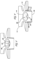
- FIG. 1 is a top view of the dental mouthpiece.
- a dental mouthpiece 100 includes a main body portion 102 having a first end 104 and a second end 106 opposite the first end 104.
- a longitudinal axis 103 may extend from the first end 104 to the second end 106.
- a suction connector portion 108 may be coupled to the first end 104 and a cheek retractor portion 110 may be coupled to the second end 106, though in other examples the mouthpiece 100 may not have a suction connector portion 108 and/or a cheek retractor portion 110.
- a bite block 101 may also be integrated to the suction connector portion 108 near the first end 104 of the main body portion 102, though the bite block 101 may be positioned anywhere on the suction connector portion 108.
- the main body portion 101 may include a neck 120 extending from the second end 106 to the cheek retractor portion 110.
- the neck 120 may have a width 122 that is less than a width of the main body portion 102, a width of the cheek retractor portion 110, and/or a width of the suction connector portion 108, though the width 122 may be greater than the width of the main body portion 102, the cheek retractor portion 110, and/or the suction connector portion 108 in other examples.
- the suction connector portion 108, the cheek retractor portion 110, the bite block 101, and the main body portion 102 are constructed as one piece, though in other examples each of the suction connector portion 108, the cheek retractor portion 110, the bite block 101, and/or the main body 102 may be separate pieces.
- the main body portion 102, the cheek retractor portion 110, and the suction connector portion 108 (and sub-portions thereof) may be molded as one-piece, preferably by injection molding and the bite block 101 may be a separate piece attachable to the suction connector portion 108.
- the mouthpiece 100 may be made of a material that is flexible, resilient, translucent, and conducive to injection molding. Such a material may include thermoplastic elastomer.
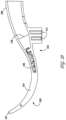
- FIG. 2 is an isometric view of a dental mouthpiece shown in FIG. 1 .
- the main body portion 102 may be shaped in a curve.
- the mouthpiece 100 is made of a flexible and resilient material (e.g., thermoplastic elastomer)
- the mouthpiece 100 may be bent when placed in a patient's mouth to conform to the shape of the mouth.
- the suction connector portion 108 may protrude from one side of the patient's mouth, while the main body portion 102 lies against the back of the patient's mouth, and the cheek retractor portion 110 presses against the patient's cheek on the opposite side of the patient's mouth.
- the cheek retractor portion 110 may be configured to press against and retract a patient's cheek away from the patient's teeth on an opposite side of the patient's mouth than the side from which the connection portion 108 extends.
- the flexibility of the material used to form the mouthpiece 100 allows for some bending when placed in the patient's mouth, but the resilience of the material further allows the mouthpiece 100 to apply pressure against a part of the patient's mouth when the mouthpiece 100 is released from bending.
- the material is resilient enough, for example, to allow the cheek retractor portion 110 to press against the inside of the patient's cheek with such pressure being sufficient to move the cheek away from the patient's teeth.
- the cheek retractor portion 110 is illustrated as a hammerhead distal region, which may be attached to the main body portion 102.
- the cheek retractor portion 110 may be solid in some examples, though may be hollow in other examples.
- the main body portion 102 may comprise an anterior wall 112 on an inner part of the curve and a posterior wall 114 (also seen in FIG. 4 ) on an outer part of the curve.
- the anterior wall 112 may face a front of the patient's mouth and the posterior wall 114 may face a back of the patient's mouth.
- the anterior wall 112 and the posterior wall 114 of the main body portion 102 may be configured in parallel to each other.
- the anterior wall 112 has a defined shape that may correspond to the defined shape of the posterior wall 114, though the anterior wall 112 may be a different shape than the posterior wall 114 in other examples.
- the defined shape may be wider at the first end 104 and narrower at the second end 106.
- the shape corresponds to a shield shape though the shape may be, for example, a square, a straight line arrow, a rectangle, a star, an oval, a circle, or a shape that generally conforms to the intraoral shape of the patient's mouth.
- Differently-sized mouthpieces may be provided for differently-sized mouths of adults and children.
- Part of the shape at the first end 104 may be formed with thicker walls than the rest of the main body portion 102. Such thickening may provide additional stability at the first end 104.
- the anterior wall 112 and the posterior wall 114 are capable of blocking an airway of the patient, while the bite block 101 is positioned between the patient's teeth, the suction connector portion 108 extends from one side of the patient's mouth, and the cheek retractor portion 110 presses against the cheek on the opposite side of the patient's mouth.
- the main body portion 102 may also include openings 140 located on the anterior wall 112 and/or the posterior wall 114.
- Such openings 140 e.g., perforations, slit, aperture, etc.
- the openings 140 may be positioned on a perimeter of the shape of the anterior wall 112 and/or the posterior wall 114.
- the openings 140 may be positioned on either side of the neck 120 on the anterior wall 112 and/or the posterior wall 114.
- the openings 140 are apertures.
- the apertures are each the same size, though in other examples some or all of the apertures may be different sizes.
- FIG. 3 is a rear view of the dental mouthpiece shown in FIG 1 .
- the suction connector portion 108 may be oval-shaped and also attached to the main body portion 102.
- the suction connector portion 108 may be formed with thicker walls than the main body portion 102 and configured to attach to a high-suction vacuum adapter and to assist in transferring water, saliva, and debris from the interior space 126 to the external adapter for removal.
- the suction connector portion 108 may also include an internal stop to assist in sliding the mouthpiece onto the adapter to a desired depth.
- the superior wall 116 in FIG. 3 may be used herein to refer to the side that rests against a roof of a patient's mouth when placed therein, and the inferior wall 118 may be used to refer to the side that rests against the floor of the patient's mouth.
- the superior wall 116 and inferior wall 118 may be formed identically, which may allow for the mouthpiece to change orientation such that the superior wall 116 may appear as the inferior wall 118 and vice versa, in the new orientation.
- the superior wall 116 and the inferior wall 118 of the main body portion 101 may serve to protect and separate the top of the mouth and the bottom of the mouth/tongue.
- the main body portion 101 may also serve to protect the back of the mouth (e.g., throat and airway) from falling debris.
- FIG. 4 is a bottom view of the dental mouthpiece shown in FIG 1 .
- the anterior wall 112 and the posterior wall 114 may be connected to each other at by at least one connector 124.
- the suction connector portion 108 may have a cutout 142 (e.g., which may be shaped as a logo, a rectangular notch, a square notch, or a circular notch, or any shaped notch) providing extra interlocking with a corresponding protrusion (e.g., which may also be shaped as a logo, a rectangular protrusion, a square protrusion, or a circular protrusion, or any shaped protrusion) on an external high-suction vacuum adapter.
- a cutout 142 e.g., which may be shaped as a logo, a rectangular notch, a square notch, or a circular notch, or any shaped protrusion
- the bite block 101 may be reinforced by bite block openings 141 to create cavities in the bite block to result in a more stable bite block.
- the bite block openings 141 may be two parallel rectangular openings that open at the bottom of the bite block.
- the bite block openings 141 may extend up to the suction connector portion 108 but not extending past the thickness of the suction connector portion 108.
- FIG. 5 is a coronal top cross section view of the dental mouthpiece shown in FIG. 1 .
- the main body portion 102 may include the bridge structure 136 that protrudes from the interior surface 135 of the posterior wall 114, as shown in FIG. 5 and also visible in FIGS. 7 and 8 .
- the bridge structure 136 may follow the shape of a logo (e.g., an arrowhead or shield).
- the bridge structure may have a gap at the tip of the arrowhead shape, creating an open arc instead of a point of an arrow.
- the bridge structure 136 may be centrally-located in the main body portion 110 of the mouthpiece 100.
- such bridge structure 136 may protrude from the interior surface 135 in a wave shape with bridge crests 137 and bridge troughs 138. In other embodiments, the bridge structure 136 may protrude in the shape of battlements or trapezoids.
- the bridge crests 137 provide a plurality of contact points that are generally separate from the anterior wall 112.
- the bridge crests 137 near the opening 146 of the suction connector portion 108 may have a greater height than the bridge crests 137 further from the opening 146, as visible in FIGS. 7 and 8 .
- the bridge crests 137 near the opening 146 of the suction connection portion 108 may also be longer than the bridge crests 137 further away from the suction connection portion 108 as shown later in FIG.
- the bridge troughs 138 may be substantially flush or extend above the interior surface 135.
- the bridge crests 137 contact the anterior wall 112 during suction to keep the anterior wall 112 spaced away from the posterior wall 114 during suction, thereby preventing collapse of the anterior wall 112 or the posterior wall 114 into the interior space 126 so that debris and/or water can be evacuated through the interior space 126.
- the bridge troughs 138 provide gaps that allow for suction of air, fluids, and small debris through the bridge structure 136.
- the bridge structure 136 may be smooth, may include sharp crests and sharp troughs, circular crests and circular troughs, square crests and square troughs, or shape or combination of shapes of crests and troughs.
- the main body portion 102 may further include a stability bar 143, shown in FIG. 5 and also visible in FIG. 7 , that extends from approximately the center of the main body portion 102 toward the cheek retractor portion 110.
- a stability bar 143 may protrude from the interior surface 135 of the posterior wall 114 along the longitudinal axis 103.
- the stability bar 143 begins from the open arc of the bridge structure 136 and continue along the longitudinal axis 103 towards the second end 106 past the neck 120 and ends before reaching the cheek retractor portion 110.
- the stability bar 143 may protrude from the interior surface 135 of the posterior wall 114 towards the interior surface 113 of the anterior wall 112.
- the stability bar 143 may be of any height ranging from the height of the interior space 126 or any height less than the interior space 126.
- the stability bar 143 may have attached connectors 124 at specific locations that may attach the anterior wall 112 to the posterior wall 114.
- the connectors 124 on the stability bar 143 may assist with retraction, stability, support and curvature of the mouthpiece 100 during suction.
- FIG. 6 is a side view of the dental mouthpiece shown in FIG. 1 .
- FIG. 6 illustrates the view of the inferior side that rests against the floor of the patient's mouth.
- the anterior wall 112 and the posterior wall 114 are spaced from each other and define the interior space 126.
- the interior space 126 is generally open and unobstructed, thereby allowing for suction to flow throughout the interior space 126.
- the interior space 126 between the anterior wall 112 and the posterior wall 114 generally follows the same defined shape of the anterior wall 112 and the posterior wall 114.
- the interior space 126 extends through the neck 120, though in other examples the interior space 126 may not extend through the neck 120.
- the interior space 126 extends through the neck 120 and into the cheek retractor portion 120.
- the anterior intervening wall 127 includes an alternating crest 130 and trough 132.
- the crests 130 are a flat surface and the troughs 132 are a cylindrical cutout surface, though the crests 130 and the troughs 132 may be any shape.
- the crests 130 and the troughs 132 extend the entire depth of the anterior intervening wall 127, though in other examples the crests 130 and/or the troughs 132 may extend partially along the anterior intervening wall 127.
- the crests 130 and the troughs 132 may provide further retraction, stability, support and curvature to the mouthpiece 100.
- the posterior wall 114 may have a corresponding at least one posterior intervening wall 134 that extends from at least one edge 133 of the posterior wall 114 and partially extends towards the anterior wall 112.
- the posterior intervening wall 134 may likewise exhibit ridges that are the same, a mirror image, or different from the anterior intervening wall 127.
- the ridges of the anterior intervening wall 127 may be aligned with the ridges of the posterior intervening wall 134, as shown in FIG. 6 .
- the anterior intervening wall 127 and the posterior intervening wall 134 and their respective aligned ridges may form an open mesh between the anterior wall 112 and the posterior wall 114.
- Such open mesh may follow the edges 128,133 of each of the anterior wall 112 and the posterior wall 114 from the first end 104 to the second end 106.
- the open mesh between the anterior intervening wall 127 and the posterior intervening wall 134 allows for suction of air, fluids, and small debris from patient's mouth, through the mesh into the interior space 126 and into the suction connector portion 108 towards a suction source.
- the anterior intervening wall 127 may join with the posterior intervening wall 134 at the superior wall 116 and the inferior wall 118 at near the suction connector portion 108 of the main body at the first end 104.
- the anterior intervening wall 127 may also join with the posterior intervening wall 134 at the superior wall 116 and the inferior wall 118 near the cheek retractor portion 110 at the second end 106.
- the anterior intervening wall 127 may join with the posterior intervening wall 134 at the cheek retractor portion 110.
- FIG. 7 is a side of the dental mouthpiece shown in FIG. 1 with an anterior wall of the mouthpiece pulled away from a posterior wall of the mouthpiece.
- the at least one connector 124 may span the distance between the anterior wall 112 and the posterior wall 114 within the interior space 126. In other words, the connector 124 may be attached to an interior surface 135 of the posterior wall 114 and to an interior surface 113 of the anterior wall 112.
- the at least one connector 124 may provide structural rigidity to the mouthpiece 100 and may be a pillar, column, wall, or the like. In the illustrated example, the at least one connector 124 includes three connectors, each in the shape of a pillar and linearly spaced from each other.
- FIG. 8 is a transverse cross section view of the dental mouthpiece shown in FIG. 1 .
- the bridge crests 137 near the opening 146 of the suction connector portion 108 may have a greater height than the bridge crests 137 further from the opening 146.
- the bridge crests 137 near the opening 146 of the suction connection portion 108 may also be longer than the bridge crests 137 further away from the suction connection portion 108.
- FIG. 9 is a transverse cross section view of the dental mouthpiece in FIG. 1 .
- FIG 9 illustrates where the suction connector attaches to the main body.
- the suction connector portion 108 may be oval-shaped and also attached to the main body portion 102 in a seamless transition until the main body reaches the bridge structure 136, where the bridge crests 137 and the bridge troughs 138 may partially block the opening of the main body portion 102 near the suction connector portion 108.
- the bite block 101 is attached on the outside of the suction connector portion 108 such a manner that the bite block does not interrupt the opening of the suction connector potion 108.
- the suction connector portion 108 may include an opening 146 (also shown in FIG. 5 ), that opens into an interior space 126 of the main body portion 102 to allow for fluid communication between the interior space 126 and the suction connector portion 108.
- At least one suction connector portion wall 144 may extend from the anterior wall 112 to the posterior wall 114 near the opening 146 of the suction connector portion 108 to prevent collapse of the anterior wall 112 and the posterior wall 114 during suctioning.
- the at least one suction connector portion wall 144 includes a pair of walls positioned on either side of the opening 146 of the suction connector portion 108.
- FIG. 10 is a cross section view of an embodiment of the dental mouthpiece shown in FIG. 1 with a wall connector.
- the connector 124 connects the anterior wall 112 with the posterior wall 114 at the longitudinal axis 103 as a solid wall.
- the connector 124 extends from the neck 120 at the second end 106 some distance away from the cheek retractor portion 110 towards the first end 104 along the longitudinal axis 103 and stops near the opening of the bridge structure 136 around the mid-point of the main body portion 102.
- the connector 124 may extend along the longitudinal axis 103 and stop anywhere within the interior space 126 of the main body portion.
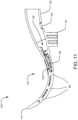
- FIG. 11 is a longitudinal cross section view of an embodiment of the dental mouthpiece shown in FIG. 1 with column connectors.
- the connector 124 connects the anterior wall 112 with the posterior wall 114 at the longitudinal axis 103 as three evenly spaced cylindrical pillars in line with the stability bar 143.
- a first connector is positioned in the main body portion 102, a second connector is positioned near the neck 120, and a third connector is spaced near the cheek retractor portion 110.
- the linear spacing of the three connectors may provide additional rigidity to the neck 120, while maintaining a narrow width 122 of the neck 120.
- such connectors 124 may be located in the area where a positioned mouthpiece 100 begins to wrap from one side of the mouth, to the back of the mouth, then to the other side of the mouth, thereby assisting in shaping the mouthpiece 100 to the general intraoral shape of a patient's mouth.
- the at least one connector 124 may include one connector, two connectors, or more than two connectors and each connector may be positioned anywhere on the mouthpiece 100.
- the at least one connector 124 is a rib that extends from the main body portion 102, through the neck 120, and to the cheek retractor portion 110.
- the mouthpiece as described herein may be used with a one-piece, autoclavable, high-suction vacuum adapter.
- a high-suction vacuum body adapter may be made of a single homogenous material. Having a single lever design, such a vacuum adapter may function in the same manner as all the current high-suction vacuum evacuators and saliva ejectors in controlling the removal of water, saliva, and debris from the oral cavity to the outside vacuum source.
- the single lever may be designed to control the removal of water, saliva, and debris from the at least partially enclosed so main body through a single, large evacuation conduit within the suction connector portion.
Landscapes
- Health & Medical Sciences (AREA)
- Life Sciences & Earth Sciences (AREA)
- Animal Behavior & Ethology (AREA)
- Veterinary Medicine (AREA)
- Public Health (AREA)
- General Health & Medical Sciences (AREA)
- Dentistry (AREA)
- Epidemiology (AREA)
- Oral & Maxillofacial Surgery (AREA)
- Engineering & Computer Science (AREA)
- Surgery (AREA)
- Biomedical Technology (AREA)
- Nuclear Medicine, Radiotherapy & Molecular Imaging (AREA)
- Physics & Mathematics (AREA)
- Biophysics (AREA)
- Optics & Photonics (AREA)
- Pathology (AREA)
- Radiology & Medical Imaging (AREA)
- Heart & Thoracic Surgery (AREA)
- Medical Informatics (AREA)
- Molecular Biology (AREA)
- Manufacturing & Machinery (AREA)
- Mechanical Engineering (AREA)
- Dental Tools And Instruments Or Auxiliary Dental Instruments (AREA)
Claims (15)
- Zahnärztliches Mundstück (100), das in einem Bogen geformt ist, wobei das zahnärztliche Mundstück (100) umfasst:einen Hauptkörperabschnitt (102) an einem zentralen Teil des Bogens mit einem ersten Ende (104) und einem zweiten Ende (106), wobei der Hauptkörperabschnitt (102) eine vordere Wand (112) innerhalb des Bogens und eine hintere Wand (114) außerhalb des Bogens und beabstandet von der vorderen Wand (112) hat, wobei die vordere Wand (112) und die hintere Wand (114) einen Innenraum (126) definieren, wobei mindestens ein Verbinder (124) die vordere Wand (112) mit der hinteren Wand (114) verbindet;einen Sauganschlussabschnitt (108), der mit dem ersten Ende (104) verbunden ist, wobei der Sauganschlussabschnitt (108) den Innenraum (126) mit einer Vakuumsaugquelle verbindet; undein mit dem zweiten Ende (106) verbundener Wangenspreizabschnitt (110);dadurch gekennzeichnet, dass:
das zahnärztliche Mundstück (100) mindestens eine Zwischenwand (127, 134) umfasst, die sich von einer Kante (128) der vorderen Wand (112) teilweise in Richtung der hinteren Wand (114) erstreckt oder sich von einer Kante (133) der hinteren Wand (114) teilweise in Richtung der vorderen Wand (112) erstreckt, wobei die mindestens eine Zwischenwand (127, 134) eine Vielzahl von abwechselnden Erhebungen (130) und Vertiefungen (132) hat. - Mundstück nach Anspruch 1, wobei der mindestens eine Verbinder (124) eine zylindrisch geformte Stütze ist, oder wobei der mindestens eine Verbinder (124) eine Wand ist, die sich im Hauptkörperabschnitt (102) im Innenraum (126) in Längsrichtung erstreckt.
- Mundstück nach Anspruch 1 oder 2, ferner umfassend eine Brückenstruktur (136) im Innenraum (126), die von der hinteren Wand (114) vorsteht, wobei die Vorsprünge zinnenförmig sind, mit beabstandeten Erhebungen (130, 137), wobei vorzugsweise die Vorsprünge in der Nähe des Sauganschlusses (108) in größerer Höhe und Länge sind, oder die Räume zwischen den Erhebungen (130, 137) Vertiefungen (132, 138) der Zinnenform sind.
- Mundstück nach Anspruch 1, 2 oder 3, wobei die abwechselnden Erhebungen (130, 137) und Vertiefungen (132, 138) an der mindestens einen Zwischenwand (127, 134) halbkreisförmig sind.
- Mundstück nach einem der vorhergehenden Ansprüche, wobei die mindestens eine Zwischenwand (127, 134) unterschiedliche Höhen aufweist, um die Stabilität des Hauptkörperteils (102) zu erhalten.
- Mundstück nach einem der vorhergehenden Ansprüche, wobei die Vertiefungen (132, 138) der mindestens einen Zwischenwand (127, 134) in ihrer Größe abnehmen, wenn sich die Vertiefungen (132, 138) dem Wangenspreizabschnitt (110) nähern.
- Mundstück nach einem der vorhergehenden Ansprüche, wobei die mindestens eine Zwischenwand (127) und eine weitere Zwischenwand (134) an einem Punkt zusammentreffen, an dem der Sauganschluss (108) auf den Hauptkörper (102) trifft.
- Mundstück nach einem der vorhergehenden Ansprüche, wobei die mindestens eine Zwischenwand (127) und die andere Zwischenwand (134) an einem Punkt zusammentreffen, an dem der Hauptkörper (102) auf den Wangenspreizabschnitt (110) trifft.
- Mundstück nach einem der vorhergehenden Ansprüche, das ferner einen Bissblock (101) umfasst, der in den Sauganschlussabschnitt (108) integriert ist, wobei der Bissblock (101) zusätzlichen Druckwiderstand und verringerte Komprimierbarkeit während des Beißens durch einen Patienten bietet.
- Mundstück nach einem der vorhergehenden Ansprüche, bei dem der Hauptkörperabschnitt (102), der Sauganschlussabschnitt (108) und der Wangenspreizabschnitt (110) durch Spritzgießen als ein Stück geformt sind.
- Mundstück nach einem der vorhergehenden Ansprüche, wobei das Material, aus dem der Hauptkörper (102), der Sauganschlussabschnitt (108) und der Wangenspreizabschnitt (110) bestehen, ein flexibles, lichtdurchlässiges, hochwärmebeständiges, autoklavierbares Material auf Silikonbasis ist.
- Mundstück nach einem der vorhergehenden Ansprüche, wobei die hintere Wand (114) ferner eine Stabilitätsstrebe (143) aufweist, die von einer Innenfläche der hinteren Wand (114) und entlang einer Längsachse des Hauptkörpers (102) vorsteht, und wobei vorzugsweise der mindestens eine Verbinder (124) gleichmäßig beabstandet entlang der Stabilitätsstrebe (143) liegt.
- Mundstück nach einem der vorhergehenden Ansprüche, wobei der Sauganschlussabschnitt (108) eine Aussparung aufweist, die einem Vorsprung an einem Vakuumadapter-Verriegelungssitz entspricht.
- Mundstück nach einem der vorhergehenden Ansprüche, wobei der Sauganschlussabschnitt (108) mit einer Vakuumquelle verbunden ist, wobei Aktivierung der Vakuumquelle ein Ansaugen von Fluiden aus dem Innenraum (126) des Hauptkörpers (102) bewirkt, und wobei vorzugsweise die Aktivierung der Vakuumquelle Fluide von einer Außenseite des Hauptkörpers (102) durch die Erhebungen (130, 137) und Vertiefungen (132, 138) der mindestens einen Zwischenwand (127, 134) in den Innenraum (126) des Hauptkörpers (102) zieht.
- Mundstück nach einem der vorhergehenden Ansprüche, wobei der Wangenspreizabschnitt (110) eine Oberfläche aufweist, die Druck basierend auf der Nachgiebigkeit des Wangenspreizabschnitts (110) ausübt.
Applications Claiming Priority (2)
| Application Number | Priority Date | Filing Date | Title |
|---|---|---|---|
| US201962846353P | 2019-05-10 | 2019-05-10 | |
| PCT/US2020/032228 WO2020231864A1 (en) | 2019-05-10 | 2020-05-08 | Dental mouthpiece |
Publications (4)
| Publication Number | Publication Date |
|---|---|
| EP3965637A1 EP3965637A1 (de) | 2022-03-16 |
| EP3965637A4 EP3965637A4 (de) | 2023-05-24 |
| EP3965637B1 true EP3965637B1 (de) | 2024-12-18 |
| EP3965637C0 EP3965637C0 (de) | 2024-12-18 |
Family
ID=73045920
Family Applications (1)
| Application Number | Title | Priority Date | Filing Date |
|---|---|---|---|
| EP20804801.7A Active EP3965637B1 (de) | 2019-05-10 | 2020-05-08 | Dentales mundstück |
Country Status (14)
| Country | Link |
|---|---|
| US (7) | US11826217B2 (de) |
| EP (1) | EP3965637B1 (de) |
| JP (1) | JP7617081B2 (de) |
| KR (1) | KR20220103035A (de) |
| AU (1) | AU2020274979B2 (de) |
| BR (1) | BR112021022474A2 (de) |
| CA (1) | CA3139689A1 (de) |
| CO (1) | CO2021016591A2 (de) |
| ES (1) | ES3000104T3 (de) |
| MX (1) | MX2021013694A (de) |
| PH (1) | PH12021552855A1 (de) |
| SG (1) | SG11202112319YA (de) |
| TW (1) | TW202108088A (de) |
| WO (1) | WO2020231864A1 (de) |
Cited By (2)
| Publication number | Priority date | Publication date | Assignee | Title |
|---|---|---|---|---|
| US12290418B2 (en) | 2012-12-07 | 2025-05-06 | Solmetex, Llc | Intraoral device |
| USD1091807S1 (en) | 2019-05-10 | 2025-09-02 | Solmetex, Llc | Mouthpiece |
Families Citing this family (9)
| Publication number | Priority date | Publication date | Assignee | Title |
|---|---|---|---|---|
| US11589969B2 (en) | 2012-12-07 | 2023-02-28 | Solmetex, Llc | Intraoral device with mesh |
| US11737739B2 (en) | 2015-04-21 | 2023-08-29 | Ascentcare Dental Products, Inc. | Dental instrument assemblies and components for use within dental instrument assemblies |
| CN108430380B (zh) * | 2015-06-10 | 2022-06-07 | 必备外科股份有限公司 | 应用在口腔外科手术中的防护装置 |
| US12226273B2 (en) * | 2020-05-04 | 2025-02-18 | Stoma Ventures, LLC | Disposable dental aerosol device |
| USD1027185S1 (en) * | 2021-03-12 | 2024-05-14 | Aliva AS | Mouthpiece |
| US11793617B2 (en) * | 2021-05-31 | 2023-10-24 | Cao Group, Inc. | Oral suction device |
| EP4285952A1 (de) * | 2022-06-01 | 2023-12-06 | Ivoclar Vivadent AG | Speichelsauger |
| US20250288400A1 (en) * | 2024-03-12 | 2025-09-18 | Ascentcare Dental Products, Inc. | Intraoral Device for Isolation and Fluid Evacuation |
| USD1097158S1 (en) * | 2024-05-17 | 2025-10-07 | Austin R. Ritter | Dental mouthpiece |
Family Cites Families (131)
| Publication number | Priority date | Publication date | Assignee | Title |
|---|---|---|---|---|
| US50461A (en) | 1865-10-17 | Improvement in dental apparatus | ||
| US1471207A (en) | 1922-05-08 | 1923-10-16 | Napoleon B Riddle | Sanitary individual saliva ejector |
| US1731322A (en) | 1927-10-20 | 1929-10-15 | Napoleon B Riddle | Saliva ejector |
| US2019612A (en) | 1933-12-01 | 1935-11-05 | Westinghouse Lamp Co | X-ray tube and x-ray screen supporting structure |
| US2937445A (en) | 1956-10-19 | 1960-05-24 | Norman R Erickson | Dental appliance |
| US3090122A (en) | 1961-01-18 | 1963-05-21 | Norman R Erickson | Dental appliance |
| US3101543A (en) | 1961-05-15 | 1963-08-27 | Herbert A Baughan | Dental saliva ejectors |
| US3379192A (en) * | 1965-05-10 | 1968-04-23 | Lamar G. Warren Jr. | Dental treatment device |
| US3453735A (en) | 1965-08-23 | 1969-07-08 | Richard E Burt | Dental aspirator |
| US3489141A (en) * | 1966-12-29 | 1970-01-13 | Lamar G Warren Jr | Dental treatment device |
| US3516160A (en) | 1968-03-18 | 1970-06-23 | Pelton & Crane Co | Dental aspirating cuspidor |
| US3802081A (en) | 1971-01-29 | 1974-04-09 | W Rogers | Tongue controller saliva ejector |
| US3758950A (en) | 1971-08-25 | 1973-09-18 | K Krouzian | Dental ejector equipment |
| US3768477A (en) | 1972-06-05 | 1973-10-30 | R Anders | Tongue depressing aspirating tip |
| US3877691A (en) * | 1972-09-12 | 1975-04-15 | Beatrice D Foster | Shield for venting gases away from anesthesiologist |
| US3857181A (en) | 1973-07-26 | 1974-12-31 | B Rappaport | Dental shield |
| US3924333A (en) * | 1974-09-09 | 1975-12-09 | Norman Erickson | Dental appliance |
| US4024642A (en) | 1975-08-26 | 1977-05-24 | Johnson & Johnson | Dental appliance |
| US4083115A (en) | 1976-03-15 | 1978-04-11 | Mckelvey Thomas H | Dental saliva ejector |
| US4017975A (en) | 1976-03-22 | 1977-04-19 | Wesley Grant Johnson | Saliva ejector and chin holder therefor |
| US4167814A (en) | 1977-04-11 | 1979-09-18 | Schubert Robert E | Mouth prop and oral evacuation device |
| US4192071A (en) | 1978-01-30 | 1980-03-11 | Norman Erickson | Dental appliance |
| US4237574A (en) * | 1978-08-07 | 1980-12-09 | Kelly J Robert | Tooth cleaning apparatus |
| USD267586S (en) | 1980-04-30 | 1983-01-11 | Hatlen Roger A | Dental mouth prop |
| US4511329A (en) | 1984-01-26 | 1985-04-16 | Diamond Michael K | Moisture controlling lingual dental mirror |
| GB2170106B (en) | 1985-01-28 | 1988-10-05 | Dr Kenneth B Liegner | Bite block |
| US5037298A (en) | 1985-11-25 | 1991-08-06 | Hickham John J | Apparatus and improved process for removing saliva while retracting cheeks and lips |
| US4718662A (en) | 1985-12-26 | 1988-01-12 | North Richard B | Tongue positioning and exercising device |
| US4822278A (en) | 1987-10-16 | 1989-04-18 | The Wilkinson Dental Manufacturing Company, Inc. | Dental veneer instrument |
| US4802851A (en) | 1988-02-03 | 1989-02-07 | Rhoades Clark J | Dental appliance |
| SE464909B (sv) | 1988-02-19 | 1991-07-01 | Tandlaekare Dyfvermark Ab | Dental bitkloss foer anslutning till sugkaella |
| US5009595A (en) | 1989-07-28 | 1991-04-23 | Osborn Carl F | Dental mouth prop |
| US5078602A (en) | 1990-04-30 | 1992-01-07 | Geraldine Honoshofsky | Saliva ejector and method for cleaning the same |
| US5365624A (en) * | 1993-03-02 | 1994-11-22 | Berns Michael S | Apparatus for automatic and simultaneous caring for teeth and gums |
| US5516286A (en) | 1994-05-16 | 1996-05-14 | Kushner; Philip | Dental isolation tray particularly suited for use when applying dental sealants and method for its use |
| USD364456S (en) | 1994-05-20 | 1995-11-21 | Albert Solnit | Aspirator tip |
| US5460524A (en) | 1994-06-24 | 1995-10-24 | Anderson; Ross W. | Device and method for saliva suction with tongue retractor and bit handle |
| US5762496A (en) | 1994-09-02 | 1998-06-09 | Koping Industri-Plast Ab | Disposable dental saliva ejector |
| US5588836A (en) | 1995-10-23 | 1996-12-31 | Op-D-Op, Inc. | Mouth prop and tongue deflector apparatus |
| US5720275A (en) * | 1996-03-26 | 1998-02-24 | The Research Foundation Of State Univ. Of New York | Tracheal guide |
| US5730599A (en) | 1996-11-12 | 1998-03-24 | Pak; Elizabeth Y. | Protective dental shield |
| JP4152468B2 (ja) | 1997-01-21 | 2008-09-17 | 弘 大口 | 歯科医療用唾液吸引具 |
| AU2721597A (en) * | 1997-03-05 | 1998-09-22 | Board Of Regents, The University Of Texas System | Self-sealed irrigation system |
| US5890899A (en) | 1997-06-27 | 1999-04-06 | Intellitech Corporation | Dental isolator |
| US6241521B1 (en) | 1998-07-13 | 2001-06-05 | John E. Garrison | Bite block |
| US6974321B2 (en) | 1998-11-17 | 2005-12-13 | Innerlite, Inc. | Intraoral device |
| USD615203S1 (en) * | 1998-11-17 | 2010-05-04 | Innerlite, Inc. | Intraoral device |
| US6022214A (en) | 1998-11-17 | 2000-02-08 | Hirsch; James A. | Intraoral illumination device and method of using the same |
| US7287981B2 (en) * | 1998-11-17 | 2007-10-30 | Innerlite, Inc. | Cooling device and method for intraoral device illumination source |
| US6102701A (en) * | 1999-01-21 | 2000-08-15 | Engeron; Michael G. | Retractor apparatus |
| US6213772B1 (en) | 1999-04-14 | 2001-04-10 | Drident, L.L.C. | Oral isolation device with evacuation chambers |
| US6267591B1 (en) | 2000-04-18 | 2001-07-31 | Ricky A. Barstow | Dental prop, throat dam and retractor |
| US6223376B1 (en) * | 2000-06-13 | 2001-05-01 | Joong Woo Lee | Toothbrush for babies |
| US6672305B2 (en) * | 2001-02-26 | 2004-01-06 | Parker Medical Limited Partnership | Shallow throat orotracheal intubation guide |
| US6716029B2 (en) | 2002-08-13 | 2004-04-06 | Ultradent Products, Inc. | Anatomical tongue guards and bite block systems incorporating anatomical tongue guards |
| US6655960B2 (en) | 2001-11-01 | 2003-12-02 | Ultradent Products, Inc. | Tongue suppressing bite block adaptable to varying mouth and tongue sizes |
| US6652276B2 (en) | 2001-11-01 | 2003-11-25 | Ultradent Products, Inc. | Customizable dental bite blocks and methods for forming customized dental bite blocks |
| WO2004004589A1 (en) * | 2002-07-02 | 2004-01-15 | The Children's Hospital Of Philadelphia | Mandibular occlusal inhibitor |
| USD497426S1 (en) | 2003-02-27 | 2004-10-19 | Innerlite, Inc. | Intraoral device adapter |
| USD495799S1 (en) * | 2003-02-27 | 2004-09-07 | Innerlite, Inc. | Intraoral device |
| JP2008513127A (ja) | 2004-09-17 | 2008-05-01 | オルムコ コーポレイション | 医療装置及び針製造方法 |
| KR100964414B1 (ko) * | 2005-05-25 | 2010-06-16 | 바이오레이즈 테크놀로지, 인크. | 구강 조직 치료용 활성화된 텍스쳐 표면을 갖는 장치 |
| KR100654392B1 (ko) * | 2005-09-13 | 2006-12-06 | 김재수 | 구강조명기 |
| JP3854983B1 (ja) * | 2005-10-07 | 2006-12-06 | 光郎 猪狩 | 理想的笑顔矯正用マウスピース |
| US20080166684A1 (en) | 2007-01-09 | 2008-07-10 | Kanas David C | Dental suction appliance |
| US20080318183A1 (en) | 2007-06-23 | 2008-12-25 | Colin Suzman | Bite block with snap-in positionable fluid ejector |
| US9848959B2 (en) * | 2007-07-05 | 2017-12-26 | Orthoaccel Technologies, Inc. | Massaging or brushing bite plates |
| US8074656B2 (en) | 2007-11-13 | 2011-12-13 | Apnicure, Inc. | Methods and systems for creating pressure gradients to improve airway patency |
| US20090208898A1 (en) * | 2008-02-15 | 2009-08-20 | Glen Kaplan | Fluid jet bristle aggitation toothbrush fixture |
| US8029280B2 (en) | 2008-05-02 | 2011-10-04 | Brian P. Black | Intra-oral device and method |
| WO2009150559A1 (en) * | 2008-06-10 | 2009-12-17 | Koninklijke Philips Electronics, N.V. | Mouthpiece for brushing teeth |
| US8359692B2 (en) * | 2008-09-08 | 2013-01-29 | Brewer Gerald K | Dental cleaning device |
| US8535056B2 (en) | 2008-11-26 | 2013-09-17 | Centrix, Inc. | Dental bite block |
| EP2384160B1 (de) * | 2008-12-30 | 2017-08-23 | Koninklijke Philips N.V. | Mundstück zur zahnreinigung mit verschiedenen borstenabschnitten für verschiedene zahnbereiche |
| USD663831S1 (en) | 2009-02-06 | 2012-07-17 | Safe-Vac, LLC | Dental suction tool |
| KR100936221B1 (ko) | 2009-03-06 | 2010-01-11 | (주) 덴토존 | 타액흡입기능을 갖는 혀 보호용 팁스, 바이트 블럭 및 구강조명기 |
| US9022961B2 (en) * | 2009-07-30 | 2015-05-05 | Mcneil-Ppc., Inc. | Oral care cleaning and treating device |
| WO2011014952A1 (en) | 2009-08-04 | 2011-02-10 | University Of Manitoba | Dental apparatus |
| US20110061189A1 (en) * | 2009-09-15 | 2011-03-17 | Mark Stephen Meadows | Oral care products and methods of using and making the same |
| KR20120099679A (ko) | 2009-11-05 | 2012-09-11 | 이너라이트, 인크. | 에어 워터 진공 실린지 및 그 사용 방법 |
| KR101082826B1 (ko) | 2010-01-20 | 2011-11-11 | 엠엔엠(주) | 마우스프롭 착탈식 구강조명장치 |
| US20120219926A1 (en) * | 2010-06-18 | 2012-08-30 | S2L, Llc | Cleaning Device for Teeth and Mouth, and Cleaning Methods |
| CA2805380C (en) * | 2010-07-15 | 2017-03-07 | Anton G.C. MILO | Suction device for evacuating fumes |
| US20120115102A1 (en) * | 2010-11-04 | 2012-05-10 | Chun-Leon Chen | Hydraulic tooth cleaner |
| CN102247140A (zh) | 2011-03-24 | 2011-11-23 | 新乡医学院第三附属医院 | 一种心电多功能检查床 |
| US20130081217A1 (en) * | 2011-09-30 | 2013-04-04 | Wonjung Jeong | Motorized mouthpiece |
| US8585403B2 (en) | 2011-10-14 | 2013-11-19 | Inger-Marie Ames | Dental appliance and method for removing bodily and other fluids from a dental site |
| USD666726S1 (en) | 2011-10-28 | 2012-09-04 | Surgovations, LLC | Bite block |
| US9968421B2 (en) | 2012-03-26 | 2018-05-15 | Orthoaccel Technologies, Inc. | Tooth positioner and vibrator combination |
| FR2992161B1 (fr) * | 2012-06-26 | 2014-07-11 | Vincent Braud | Protection intra-buccale |
| US8911232B2 (en) | 2012-12-07 | 2014-12-16 | Incept, Inc. | Intraoral dental suction and isolation system |
| US11589969B2 (en) | 2012-12-07 | 2023-02-28 | Solmetex, Llc | Intraoral device with mesh |
| EP2983612B1 (de) | 2013-04-12 | 2018-08-15 | Innerlite, Inc. | Zahnärztliche aspirationsvorrichtung und verfahren zur reinigung der vorrichtung |
| US9044293B2 (en) * | 2013-05-24 | 2015-06-02 | Hari Mark Reyes | Oral cavity suction device |
| JP2016537050A (ja) * | 2013-11-18 | 2016-12-01 | チャン ユ,ヒ | 口腔型電動歯ブラシ |
| US10390916B1 (en) * | 2013-12-13 | 2019-08-27 | Edmond Rassibi | Saliva ejector appliance |
| KR101449724B1 (ko) * | 2014-02-21 | 2014-10-15 | 현기봉 | 구강세정장치 |
| USD737964S1 (en) | 2014-03-14 | 2015-09-01 | Ultradent Products, Inc. | Cheek retractor device |
| USD735858S1 (en) | 2014-05-22 | 2015-08-04 | Innerlite, Inc. | Intraoral device |
| US9358086B2 (en) | 2014-05-22 | 2016-06-07 | Innerlite, Inc. | Intraoral device and method of use |
| US10869541B2 (en) * | 2014-11-11 | 2020-12-22 | ZeroBrush, Inc. | Systems, devices, and methods for customized dental care |
| JP2016125196A (ja) | 2014-12-26 | 2016-07-11 | 勝 豊蔵 | あおり板付きスノーダンプ |
| CN104490483B (zh) * | 2015-01-12 | 2016-03-02 | 黄骅市康田医疗器械有限公司 | 自助式口腔吸唾液分离装置 |
| US11737739B2 (en) | 2015-04-21 | 2023-08-29 | Ascentcare Dental Products, Inc. | Dental instrument assemblies and components for use within dental instrument assemblies |
| US9968341B2 (en) | 2015-04-21 | 2018-05-15 | Ascentcare Dental Labs, Llc | Dental bite block assembly |
| US10575976B2 (en) * | 2015-04-30 | 2020-03-03 | Dynamic Mouth Devices, L.L.C. | Method and apparatus for weight management utilizing an intra-oral device |
| US10390734B2 (en) * | 2015-05-29 | 2019-08-27 | Bohnas Innovations LLC | Systemic biomarker sampling apparatus |
| WO2016193873A1 (en) * | 2015-06-05 | 2016-12-08 | Al-Shawi Modher Ibrahim | Surgical gas shield module with elevation system |
| US10136975B2 (en) * | 2015-12-07 | 2018-11-27 | Hari Mark Reyes | Oral cavity suction system |
| US10058407B2 (en) * | 2015-12-07 | 2018-08-28 | Hari Mark Reyes | Oral cavity suction device |
| US9956062B2 (en) * | 2015-12-07 | 2018-05-01 | Hari Mark Reyes | Oral cavity suction device |
| USD787069S1 (en) | 2016-04-20 | 2017-05-16 | Ascentcare Dental Labs | Illuminated dental accessory for holding saliva ejection tube |
| USD782047S1 (en) | 2016-04-20 | 2017-03-21 | Ascentcare Dental Labs, Llc | Dental accessory for holding a saliva ejection tube |
| USD787070S1 (en) | 2016-04-20 | 2017-05-16 | Ascentcare Dental Labs | Illuminated dental accessory with tongue suppressor |
| USD782048S1 (en) | 2016-04-20 | 2017-03-21 | Ascentcare Dental Labs, Llc | Dental bite block |
| USD868958S1 (en) | 2016-09-14 | 2019-12-03 | Hari Mark Reyes | Stylized oral cavity suction device |
| WO2018126150A1 (en) * | 2016-12-29 | 2018-07-05 | Novo Dent, Llc | Polymer dental dam clamp and related assemblies and methods |
| USD833029S1 (en) * | 2017-01-09 | 2018-11-06 | Toothshower, Llc | Gum massager |
| EP3614881A1 (de) * | 2017-04-26 | 2020-03-04 | Dental Robotics Group B.V. | Mundstück für eine zahnreinigungsvorrichtung, verfahren zum zähneputzen und zahnreinigungsvorrichtung mit dem mundstück |
| US10716651B2 (en) * | 2017-06-27 | 2020-07-21 | Dr. Pik Co., Ltd. | Oral care device and oral care method |
| EP3752095B1 (de) * | 2018-02-13 | 2024-01-10 | Eht Llc | Zahnärztliches spülgerät |
| US11160644B2 (en) * | 2018-07-02 | 2021-11-02 | PerioNovum LLC | Devices and methods for oral hygiene |
| EP3647657A1 (de) | 2018-10-29 | 2020-05-06 | Siemens Aktiengesellschaft | Speisewasserregelung für zwangdurchlauf-abhitzedampferzeuger |
| US11311362B2 (en) * | 2018-11-16 | 2022-04-26 | Gary Baker | Dental device |
| US10939979B2 (en) | 2018-11-29 | 2021-03-09 | Domenic G. Lombardi | Dental bite block device |
| US10932555B2 (en) * | 2019-02-07 | 2021-03-02 | Willo 32 Sas | Oral care appliance and a method for controlling pressure therein |
| KR20220103035A (ko) | 2019-05-10 | 2022-07-21 | 드라이쉴드, 엘엘씨 | 치과용 마우스피스 |
| US20200383560A1 (en) | 2019-06-10 | 2020-12-10 | Robinson Healthcare Limited | Intraoral surgical mouth prop |
| US12350117B2 (en) * | 2020-09-24 | 2025-07-08 | PerioNovum LLC | Oral hygiene devices configured for use with orthodontics |
| US11793617B2 (en) * | 2021-05-31 | 2023-10-24 | Cao Group, Inc. | Oral suction device |
| US20240115366A1 (en) * | 2022-10-07 | 2024-04-11 | Audrey Lawrence Rosenberg | Oral appliance for dental hygiene |
-
2020
- 2020-05-08 KR KR1020217040518A patent/KR20220103035A/ko not_active Withdrawn
- 2020-05-08 US US16/870,745 patent/US11826217B2/en active Active
- 2020-05-08 JP JP2022514453A patent/JP7617081B2/ja active Active
- 2020-05-08 EP EP20804801.7A patent/EP3965637B1/de active Active
- 2020-05-08 PH PH1/2021/552855A patent/PH12021552855A1/en unknown
- 2020-05-08 ES ES20804801T patent/ES3000104T3/es active Active
- 2020-05-08 CA CA3139689A patent/CA3139689A1/en active Pending
- 2020-05-08 SG SG11202112319YA patent/SG11202112319YA/en unknown
- 2020-05-08 WO PCT/US2020/032228 patent/WO2020231864A1/en not_active Ceased
- 2020-05-08 BR BR112021022474A patent/BR112021022474A2/pt unknown
- 2020-05-08 AU AU2020274979A patent/AU2020274979B2/en active Active
- 2020-05-08 MX MX2021013694A patent/MX2021013694A/es unknown
- 2020-05-08 TW TW109115467A patent/TW202108088A/zh unknown
-
2021
- 2021-05-07 US US29/782,643 patent/USD988505S1/en active Active
- 2021-05-07 US US29/782,644 patent/USD988506S1/en active Active
- 2021-12-07 CO CONC2021/0016591A patent/CO2021016591A2/es unknown
-
2023
- 2023-06-05 US US29/893,986 patent/USD1037436S1/en active Active
- 2023-10-03 US US18/376,309 patent/US12167948B2/en active Active
-
2024
- 2024-07-01 US US29/950,233 patent/USD1091807S1/en active Active
- 2024-12-16 US US18/983,258 patent/US20250177092A1/en active Pending
Cited By (2)
| Publication number | Priority date | Publication date | Assignee | Title |
|---|---|---|---|---|
| US12290418B2 (en) | 2012-12-07 | 2025-05-06 | Solmetex, Llc | Intraoral device |
| USD1091807S1 (en) | 2019-05-10 | 2025-09-02 | Solmetex, Llc | Mouthpiece |
Also Published As
| Publication number | Publication date |
|---|---|
| USD1091807S1 (en) | 2025-09-02 |
| BR112021022474A2 (pt) | 2022-01-04 |
| USD988505S1 (en) | 2023-06-06 |
| TW202108088A (zh) | 2021-03-01 |
| CO2021016591A2 (es) | 2022-01-28 |
| US20200352680A1 (en) | 2020-11-12 |
| US12167948B2 (en) | 2024-12-17 |
| AU2020274979B2 (en) | 2025-08-28 |
| SG11202112319YA (en) | 2021-12-30 |
| US11826217B2 (en) | 2023-11-28 |
| US20250177092A1 (en) | 2025-06-05 |
| CA3139689A1 (en) | 2020-11-19 |
| AU2020274979A1 (en) | 2021-12-09 |
| USD988506S1 (en) | 2023-06-06 |
| JP2022533276A (ja) | 2022-07-21 |
| CN114302667A (zh) | 2022-04-08 |
| KR20220103035A (ko) | 2022-07-21 |
| USD1037436S1 (en) | 2024-07-30 |
| US20240024072A1 (en) | 2024-01-25 |
| EP3965637C0 (de) | 2024-12-18 |
| WO2020231864A1 (en) | 2020-11-19 |
| EP3965637A1 (de) | 2022-03-16 |
| JP7617081B2 (ja) | 2025-01-17 |
| EP3965637A4 (de) | 2023-05-24 |
| ES3000104T3 (en) | 2025-02-27 |
| PH12021552855A1 (en) | 2023-01-04 |
| MX2021013694A (es) | 2022-04-07 |
Similar Documents
| Publication | Publication Date | Title |
|---|---|---|
| EP3965637B1 (de) | Dentales mundstück | |
| US12011329B2 (en) | Intraoral device | |
| US11589970B2 (en) | Intraoral device with detachable mouth prop | |
| CN114302667B (en) | Dental oral cavity piece |
Legal Events
| Date | Code | Title | Description |
|---|---|---|---|
| STAA | Information on the status of an ep patent application or granted ep patent |
Free format text: STATUS: THE INTERNATIONAL PUBLICATION HAS BEEN MADE |
|
| PUAI | Public reference made under article 153(3) epc to a published international application that has entered the european phase |
Free format text: ORIGINAL CODE: 0009012 |
|
| STAA | Information on the status of an ep patent application or granted ep patent |
Free format text: STATUS: REQUEST FOR EXAMINATION WAS MADE |
|
| 17P | Request for examination filed |
Effective date: 20211209 |
|
| AK | Designated contracting states |
Kind code of ref document: A1 Designated state(s): AL AT BE BG CH CY CZ DE DK EE ES FI FR GB GR HR HU IE IS IT LI LT LU LV MC MK MT NL NO PL PT RO RS SE SI SK SM TR |
|
| DAV | Request for validation of the european patent (deleted) | ||
| DAX | Request for extension of the european patent (deleted) | ||
| A4 | Supplementary search report drawn up and despatched |
Effective date: 20230420 |
|
| RIC1 | Information provided on ipc code assigned before grant |
Ipc: A61C 17/10 20060101ALI20230414BHEP Ipc: A61C 17/06 20060101ALI20230414BHEP Ipc: A61C 17/00 20060101ALI20230414BHEP Ipc: A61B 1/24 20060101AFI20230414BHEP |
|
| GRAP | Despatch of communication of intention to grant a patent |
Free format text: ORIGINAL CODE: EPIDOSNIGR1 |
|
| STAA | Information on the status of an ep patent application or granted ep patent |
Free format text: STATUS: GRANT OF PATENT IS INTENDED |
|
| INTG | Intention to grant announced |
Effective date: 20240710 |
|
| RAP1 | Party data changed (applicant data changed or rights of an application transferred) |
Owner name: SOLMETEX, LLC |
|
| GRAS | Grant fee paid |
Free format text: ORIGINAL CODE: EPIDOSNIGR3 |
|
| GRAA | (expected) grant |
Free format text: ORIGINAL CODE: 0009210 |
|
| STAA | Information on the status of an ep patent application or granted ep patent |
Free format text: STATUS: THE PATENT HAS BEEN GRANTED |
|
| AK | Designated contracting states |
Kind code of ref document: B1 Designated state(s): AL AT BE BG CH CY CZ DE DK EE ES FI FR GB GR HR HU IE IS IT LI LT LU LV MC MK MT NL NO PL PT RO RS SE SI SK SM TR |
|
| REG | Reference to a national code |
Ref country code: CH Ref legal event code: EP |
|
| REG | Reference to a national code |
Ref country code: DE Ref legal event code: R096 Ref document number: 602020043439 Country of ref document: DE |
|
| REG | Reference to a national code |
Ref country code: IE Ref legal event code: FG4D |
|
| U01 | Request for unitary effect filed |
Effective date: 20241218 |
|
| U07 | Unitary effect registered |
Designated state(s): AT BE BG DE DK EE FI FR IT LT LU LV MT NL PT RO SE SI Effective date: 20250102 |
|
| REG | Reference to a national code |
Ref country code: ES Ref legal event code: FG2A Ref document number: 3000104 Country of ref document: ES Kind code of ref document: T3 Effective date: 20250227 |
|
| PG25 | Lapsed in a contracting state [announced via postgrant information from national office to epo] |
Ref country code: HR Free format text: LAPSE BECAUSE OF FAILURE TO SUBMIT A TRANSLATION OF THE DESCRIPTION OR TO PAY THE FEE WITHIN THE PRESCRIBED TIME-LIMIT Effective date: 20241218 |
|
| PG25 | Lapsed in a contracting state [announced via postgrant information from national office to epo] |
Ref country code: NO Free format text: LAPSE BECAUSE OF FAILURE TO SUBMIT A TRANSLATION OF THE DESCRIPTION OR TO PAY THE FEE WITHIN THE PRESCRIBED TIME-LIMIT Effective date: 20250318 |
|
| PG25 | Lapsed in a contracting state [announced via postgrant information from national office to epo] |
Ref country code: GR Free format text: LAPSE BECAUSE OF FAILURE TO SUBMIT A TRANSLATION OF THE DESCRIPTION OR TO PAY THE FEE WITHIN THE PRESCRIBED TIME-LIMIT Effective date: 20250319 |
|
| PG25 | Lapsed in a contracting state [announced via postgrant information from national office to epo] |
Ref country code: RS Free format text: LAPSE BECAUSE OF FAILURE TO SUBMIT A TRANSLATION OF THE DESCRIPTION OR TO PAY THE FEE WITHIN THE PRESCRIBED TIME-LIMIT Effective date: 20250318 |
|
| U20 | Renewal fee for the european patent with unitary effect paid |
Year of fee payment: 6 Effective date: 20250521 |
|
| PG25 | Lapsed in a contracting state [announced via postgrant information from national office to epo] |
Ref country code: SM Free format text: LAPSE BECAUSE OF FAILURE TO SUBMIT A TRANSLATION OF THE DESCRIPTION OR TO PAY THE FEE WITHIN THE PRESCRIBED TIME-LIMIT Effective date: 20241218 |
|
| PG25 | Lapsed in a contracting state [announced via postgrant information from national office to epo] |
Ref country code: PL Free format text: LAPSE BECAUSE OF FAILURE TO SUBMIT A TRANSLATION OF THE DESCRIPTION OR TO PAY THE FEE WITHIN THE PRESCRIBED TIME-LIMIT Effective date: 20241218 |
|
| PGFP | Annual fee paid to national office [announced via postgrant information from national office to epo] |
Ref country code: GB Payment date: 20250528 Year of fee payment: 6 Ref country code: ES Payment date: 20250602 Year of fee payment: 6 |
|
| PG25 | Lapsed in a contracting state [announced via postgrant information from national office to epo] |
Ref country code: IS Free format text: LAPSE BECAUSE OF FAILURE TO SUBMIT A TRANSLATION OF THE DESCRIPTION OR TO PAY THE FEE WITHIN THE PRESCRIBED TIME-LIMIT Effective date: 20250418 |
|
| PG25 | Lapsed in a contracting state [announced via postgrant information from national office to epo] |
Ref country code: SK Free format text: LAPSE BECAUSE OF FAILURE TO SUBMIT A TRANSLATION OF THE DESCRIPTION OR TO PAY THE FEE WITHIN THE PRESCRIBED TIME-LIMIT Effective date: 20241218 |
|
| PG25 | Lapsed in a contracting state [announced via postgrant information from national office to epo] |
Ref country code: CZ Free format text: LAPSE BECAUSE OF FAILURE TO SUBMIT A TRANSLATION OF THE DESCRIPTION OR TO PAY THE FEE WITHIN THE PRESCRIBED TIME-LIMIT Effective date: 20241218 |
|
| PLBE | No opposition filed within time limit |
Free format text: ORIGINAL CODE: 0009261 |
|
| STAA | Information on the status of an ep patent application or granted ep patent |
Free format text: STATUS: NO OPPOSITION FILED WITHIN TIME LIMIT |
|
| 26N | No opposition filed |
Effective date: 20250919 |