EP3965606B1 - Clasp assembly - Google Patents
Clasp assembly Download PDFInfo
- Publication number
- EP3965606B1 EP3965606B1 EP20802099.0A EP20802099A EP3965606B1 EP 3965606 B1 EP3965606 B1 EP 3965606B1 EP 20802099 A EP20802099 A EP 20802099A EP 3965606 B1 EP3965606 B1 EP 3965606B1
- Authority
- EP
- European Patent Office
- Prior art keywords
- posts
- half sections
- base
- teeth
- pair
- Prior art date
- Legal status (The legal status is an assumption and is not a legal conclusion. Google has not performed a legal analysis and makes no representation as to the accuracy of the status listed.)
- Active
Links
Images



Classifications
-
- A—HUMAN NECESSITIES
- A44—HABERDASHERY; JEWELLERY
- A44C—PERSONAL ADORNMENTS, e.g. JEWELLERY; COINS
- A44C5/00—Bracelets; Wrist-watch straps; Fastenings for bracelets or wrist-watch straps
- A44C5/18—Fasteners for straps, chains or the like
- A44C5/20—Fasteners for straps, chains or the like for open straps, chains or the like
-
- A—HUMAN NECESSITIES
- A44—HABERDASHERY; JEWELLERY
- A44B—BUTTONS, PINS, BUCKLES, SLIDE FASTENERS, OR THE LIKE
- A44B11/00—Buckles; Similar fasteners for interconnecting straps or the like, e.g. for safety belts
- A44B11/25—Buckles; Similar fasteners for interconnecting straps or the like, e.g. for safety belts with two or more separable parts
- A44B11/258—Buckles; Similar fasteners for interconnecting straps or the like, e.g. for safety belts with two or more separable parts fastening by superposing one part on top of the other
-
- A—HUMAN NECESSITIES
- A44—HABERDASHERY; JEWELLERY
- A44C—PERSONAL ADORNMENTS, e.g. JEWELLERY; COINS
- A44C5/00—Bracelets; Wrist-watch straps; Fastenings for bracelets or wrist-watch straps
- A44C5/18—Fasteners for straps, chains or the like
-
- A—HUMAN NECESSITIES
- A44—HABERDASHERY; JEWELLERY
- A44D—INDEXING SCHEME RELATING TO BUTTONS, PINS, BUCKLES OR SLIDE FASTENERS, AND TO JEWELLERY, BRACELETS OR OTHER PERSONAL ADORNMENTS
- A44D2200/00—General types of fasteners
- A44D2200/10—Details of construction
- A44D2200/12—Details of construction made of two identical elements
Definitions
- This disclosure relates to a clasp assembly such as could be used, for example, in a wristband.
- Wristbands are used in a variety of situations. For example, wristbands can be used at events to authorize, locate, and/or identify participants at the event. Additionally, wristbands are ubiquitous in medical facilities as an identification and tracking device for patients undergoing medical care.
- Most wristbands include a securing feature such as an adhesive section or a clasp and, after a loop has been formed, the securing feature keeps the wristband around the person wearing it.
- a securing feature such as an adhesive section or a clasp and, after a loop has been formed, the securing feature keeps the wristband around the person wearing it.
- Such securing features can be used to adjust the length of the wristband to accommodate different tethering conditions (for example, for attachment to a large adult wrist versus a small child wrist) and, in many cases, to create a non-reversible connection to prevent non-destructive removal of the band, which also renders the identification device tamper-proof.
- Clasps are extremely valuable as securing features as they enable the comfortable wearing using pre-indexed positions that are easy to install.
- Adhesive by contrast, is less expensive to manufacture, but requires some placement skill to align and can lead to exposed adhesive that sticks to skin or hair and can make wearing uncomfortable and removal painful.
- clasps One complicating factor for the design of clasps is their assembly and insertion into wristband forms. This is done out of convenience and simplicity, but adds to the expense of manufacturing as nearly all clasps have a male and female or stud and socket type design. These two separate articles require separate sets of tooling for molds and insertion and often need to be carefully sorted during the manufacturing process.
- An improved and novel clasp assembly with interlocking engagement is disclosed herein for a wristband that is formable into a loop.
- the clasp assembly can aid in keeping the wristband in a constant loop around the person wearing the wristband, can be simple in construction, and can prohibit non-destructive removal.
- the clasp assembly is designed to have two identical half sections instead of, for example, a male and female section or otherwise differentiated half sections.
- identical half sections only a single type of half section needs to be produced for the clasp assembly instead of two unique half sections. This can save production costs by not requiring two sets of tooling for injection molding of the clasp portions. Still further, any possibility of mistake during the assembly of the half sections to a wristband can be avoided since, without unique half sections, there is no requirement that exactly one of each type of half section for the clasp assembly needs to be installed in a single wristband.
- a clasp assembly which includes a pair of identical half sections configured to be coupled together.
- Each half section includes one or more deformable features that are designed to deform during closure to create an interlocking engagement between each half section and in which the one or more deformable features are posts extending from a base of the respective half section, the posts having a wedge shape with a tooth at the distal end with the tooth having a stop surface facing the base; wherein each of the pair of identical half sections has discrete rotational symmetry; wherein, after interlocking engagement, the stop surface of a post on one half section contacts the stop surface of a post on the other half section such that the pair of identical half sections are not completely axially separable without permanent mechanical destruction of the one or more deformable features; wherein the interlocking engagement is created between the teeth at the stop surfaces.
- the pair of identical half sections is not completely axially separable without permanent mechanical destruction of the one or more deformable features.
- the clasp assembly has interlocking projections with teeth.
- the pair of identical half sections includes a base and the one or more deformable features is a plurality of posts extending axially from the base.
- Each of the posts of the identical half sections has a distal end away from the base including a tooth that radially projects from the post in which the tooth include a stop surface facing the base.
- the teeth of the posts have a wedge-like shape.
- the teeth further include tapered surfaces on angular ends thereof that narrow as the teeth extend towards the distal end of the respective post.
- the tapered surfaces on angular ends of the posts on each of the half sections may contact one another and effectuate the elastic deformation of the posts to permit the teeth of the posts to pass by one another until the stop surfaces of one of the half sections has axially passed the stop surfaces of the other one of the half sections, and the posts return to a non-deformed state which thereby creates an interlocking engagement between the posts on each of the half sections at the stop surfaces.
- each of the stop surfaces may have a corresponding angular extent between angular ends of the respective stop surface and the total summed amount of the angular extents of all of the plurality of stop surfaces on one of the half sections may exceed 180 degrees. This creates assured angular overlap between the stop surfaces of the pair of half sections with one another when the posts of the half sections are brought together in interlocking engagement.
- an alternative toothed structure in which the base may include cutouts in which the teeth of the other half section are received.
- the pair of identical half sections may include a base and the one or more deformable features may be a plurality of posts extending axially from the base.
- the base can include a plurality of cutouts spaced about a peripheral edge of the base and, when the pair of half sections are axially brought together, the plurality of posts may elastically deform over a distance of axial travel during joining until the plurality of posts snap back to engage the plurality of cutouts on the periphery of the base and restrict axial separation of the pair of half sections.
- the plurality of posts may elastically deform outward due to an engagement of an axially-inclined surface of each respective post on one of the pair of half sections with the base (or an edge or surface thereof) on the other of the pair of half sections.
- Each of the posts may include a stop surface facing the base of the half section to which the posts belong and, when the pair of half sections are axially brought together to cause engagement of the plurality of posts with the plurality of cutouts, each stop surface engages an oppositely facing surface of a corresponding cutout to restrict the axial separation of the pair of half sections.
- the deformable features may have include various segments with frustospherical concave and convex portions that can be joined together reminiscent of a ball and socket type joint.
- the pair of identical half sections may include a base with the one or more deformable features being a plurality of posts extending axially from the base. At least one of the plurality of posts may include an axially-facing concave surface (that is, axially-facing in that it faces in a radial direction facing the central axis as opposed to away from the axis) and at least one of the plurality of posts may include an outwardly-facing convex surface.
- the axially-facing concave surfaces are configured for interlocking engagement with the outwardly-facing convex surfaces when the pair of half sections are axially brought together.
- the axially-facing concave surfaces and the outwardly-facing convex surfaces may be, for example, frustospherical surfaces or elongated versions thereof.
- the number of the axially-facing concave surfaces may match the number of the outwardly-facing convex surfaces.
- Each of the pair of half sections 12 includes a base 14, which as illustrated can be generally disc-shaped.
- the base 14 can be in various other forms or shapes.
- the base 14 could be rectangular, square, triangular or other polygonal or non-polygonal shape.
- the shape of the base 14 may be altered in some cases, based on the shape of the wristband to which the clasp assembly 10 is attached.
- the teeth 16 and teeth 20 While a particular shape and size of the posts 16 and teeth 20 have been shown, one of ordinary skill in the art will appreciate certain variations may be made while maintaining the functionality described below. For example, the teeth do not need to be triangular wedge shaped, but might be longer arcs. Still further, while the stop surfaces of the teeth are illustrated on the radially outward side of the posts, it is contemplated that differently structure posts and teeth could present these stop surfaces on the radially inward facing side of the posts instead.
- This contact between the half sections 12 effectuates the elastic deformation of the posts 16 to permit the teeth 20 of the posts 16 to pass by one another until the stop surface 22 of one of the half sections 12 axially passes the stop surface 22 of the other half section 12.
- the posts 16 then deflect back or return to a non-deformed state creating an interlocking engagement between the posts 16 on each of the half sections 12 at the stop surfaces 22 as illustrated in FIG. 2 .
- this amount of angular extent necessarily creates some amount of angular overlap in joined identical half sections.
- such a total summed angular extent creates some amount of overlap of the tapered surfaces 24 so the tapers almost certainly will result in less than 180 degrees of cumulative angular extent on the distal-most end of the posts 16, which will permit these distal ends to interact together during the axial insertion of the sections 12 together to create the temporary mechanical displacement of the posts 16 and the teeth 20.
- the stop surfaces could have less than 180 degrees of extent and the primary consideration is whether the particular geometry employed readily permits one-way engagement of the teeth without the ability to separate the halves once joined.
- the interlocking engagement of the teeth 20 at the stop surfaces 22 prevents the half sections 12 from separating absent mechanical destruction of at least some of the teeth or post structure.
- a tensile pull along an axial direction opposite the assembly direction would not pull the two half sections 12 apart without destroying the teeth 20 because of the non-reversible connection at the stop surfaces 22.
- Destroying the teeth 20 would also destroy the clasp assembly 10 and prevent the wristband from staying on the person. Accordingly, the clasp assembly 10 provides a non-reversible, secure mechanism for one time-attachment that is tamper proof.
- Each of the pair of half sections 112 includes a base 114, which as illustrated can be generally disc-shaped.
- the base 114 can be in various other forms or shapes.
- the base 114 could be rectangular, square, triangular or other polygonal or non-polygonal shape.
- the shape of the base 114 may be altered in some cases or based on the shape of the wristband to which the clasp assembly 110 is to be attached.
- the base 114 has a plurality of posts 116 extending from the base 114 in a generally axial direction relative to the disc that forms the base 114 and about the central axis of the base 114. As illustrated, three posts 116 are angularly arranged around the periphery of the base 114. However, it is contemplated that there could be two, three, or more posts on each base 114 and a similar operational effect could be achieved to that which is described herein.
- each of the cutouts 130 extends axially from a first axial surface 128 of the base 114 to a second axial surface 132 of the base 114 and extends radially inward from an otherwise circular periphery of the base 114.
- the cutout 130 as illustrated is generally arcuate-shaped, with a peripheral edge jutting inwards radially towards the center of the base 114.
- each of the cutouts 130 further have a recess 134 that extends further radially inward from the periphery than the cutout 130.
- the recess 134 does not fully extend from the first axial surface 128 of the base 114 to the second axial surface 132 of the base 114, but only fractionally therebetween.
- the positioning of the posts 116 with teeth 120 and the cutouts 130 with recesses 134 is such that, as will be illustrated in FIG. 4 , the stop surfaces 122 of teeth 120 and the stop surfaces 136 of the recesses 134 will be engageable with one another. As such, there should be some rotational symmetry in the design of the half section 112 to permit this engagement and to do so at more than one angular position of the half sections 112 with respect to one another.
- FIG. 4 illustrates the clasp assembly 110 of FIG. 3 in an assembled state in which the pair of half sections 112 of the clasp assembly 110 are secured to one another.
- the plurality of posts 116 of the pair of half sections 112 and the plurality of cutouts 130 with recesses 134 are axially brought together to engage the teeth 120 of the posts 116 with the recesses 134 of the cutouts 130 (and more specifically to engage the stop surfaces 122 of the teeth 120 on the posts 116 with the stop surfaces 136 of recesses 134 of the cutouts 130 so that cannot be axially withdrawn from one another).
- the axial side of the half sections 112 having the posts 116 are made to face one another and the posts 116 of one of the half sections 112 are angularly aligned with the cutouts 130 on the other of the half sections 112.
- the inclined surface 124 of the tooth 120 comes into contact with an edge 138 of the cutout 130 between the periphery and the first axial face 128, thereby effectuating the elastic deformation of the post 116 radially outward to permit the tooth 120 of the post 116 to axially pass by the edge 138 of the cutout 130.
- the stop surface 122 of the tooth 120 then continues to move axially until the stop surface 122 passes the corresponding stop surface 136 formed by the recess 134 in the cutout 130.
- the posts 116 then deflect back or return to a non-deformed state such that each of the teeth 120 of one half section 112 nests into the corresponding recesses 134 of the other half section 112, thereby creating an interlocking engagement between the posts 116 on one of the half sections 112 with the recesses 134 in the cutouts 130 on the other half sections 112 at the stop surfaces 122 and 136.
- This engagement cannot be readily separated in tension without breaking the teeth 120, posts 116, and/or a wall of the base 114 forming part of the recess 134.
- the clasp assembly 110 provides a non-reversible, secure mechanism for one time-attachment.
- the posts 116 and teeth 120 have been shown along with those of the corresponding cutouts 130 and recesses 134, one of ordinary skill in the art will appreciate certain variations may be made while maintaining or even improving the functionality described below. For example, there could be slight undercuts on each of the stop surfaces 122 and 136 that could help to create interlocking engagement. Still further, while the arcuate length of the teeth 120 are roughly equal to the arcuate length of the recesses 134, the length of the teeth 120 could be appreciably less than the length of the recesses 134, creating a greater range of possible angular arrangements in which connection is possible. As another possibility, a regular polygonal shape may be employed such as a square or hexagon rather than a circle and that regular polygon may have alternating posts and recesses along each side or at each corner.
- each base 114 has three cutouts 130 that correspond to the three posts 116 and teeth 120.
- by maintaining some rotational symmetry in the design it is possible to have multiple orientations of alignment.
- by increasing the number of features it is possible to reduce the average amount of rotation in order to come into an aligned position in which the two halves may be joined.
- the number of the posts 116 and teeth 120 matches exactly the number of the cutouts 130 and recesses 134. However, this need not be the case. For instance, it is contemplated that there could be more recesses 134 than posts 116 with teeth 120. In such case, there could be various orientations of assembly between the two half sections 112 and some recesses may remain unoccupied even when the two half sections 112 are joined.
- the recess 134 is generally rectangular-shaped or slightly arcuate-shaped to match the cutout 130 where the recess is located in, that other geometries could be used.
- the recess 134 could be square, triangular or other polygonal or non-polygonal shape.
- the teeth on the posts may be designed to have similarly shaped mating geometries.
- the half sections could be modified such that the posts are designed to deflect radially inward (relative it the center axis of the clasp) while the recesses are formed on a centrally-facing surface to effectively reverse the positioning of the mating features and their direction of deflection.
- FIGS. 5A and 5B illustrate a half section 212 of a "cupped surfaces" style for a clasp assembly 210 can be assembled from two identical half sections 212 as illustrated in FIG. 6 . This embodiment does not fall into the scope of the present invention.
- the clasp assembly 210 includes a pair of half sections 212 that, as illustrated, are identical to one another.
- Each half section 212 can be an integrally formed unitary structure, for example, formed by plastic injection molding. By being formed from plastic, thin walls of the parts or other sections of them may be elastically deformable.
- Each of the pair of half sections 212 includes a base 214, which as illustrated can be generally disc-shaped.
- the base 214 can be in various other forms or shapes.
- the base 214 could be rectangular, square, triangular or other polygonal or non-polygonal shape.
- the shape of the base 214 may be altered in some cases, based on the shape of the wristband to which the clasp assembly 210 is attached.
- the base 214 has a plurality of posts 216 extending from the base 214 in a generally axial direction relative to the disc that forms the illustrated base 214 and about the center of the base 214. As illustrated, there are four posts 216 on each base 214 arranged with their stems in a square on the base 214. However, it is contemplated that there could be two or more posts on each base 214 and a similar operational effect could be achieved to that which is described herein. Based on the nature of the mating arrangement for this embodiment, it would be contemplated that there would be an even number of posts 216 to provide the correct number of mating partners.
- the posts 216 have alternating male and female features around the square that are shaped to engage with the posts 216 of another half section 212.
- each of the posts 216 On each half section 212, each of the posts 216 have a distal end 218 away from the base 214 and a proximal end 220 near the base 214.
- two of the posts 216 on opposing corners of the square have axially-facing concave surfaces 222 extending between their distal ends 218 and the proximal ends 220.
- the posts 216 with the axially-facing concave surface 222 together form female deformable features.
- two of the posts 216 have outwardly-facing convex surfaces 226 extending between the distal end 218 and the proximal end 220 and are on the two other opposing corners of the square.
- the posts 216 with the outwardly-facing convex surface 226 together form male deformable features.
- FIG. 6 illustrates a clasp assembly 210 constructed from a pair of identical half sections 212 as illustrated in FIGS. 5A and 5B .
- the female deformable features that is, the axially-facing concave surfaces 222
- male deformable features that is, the outwardly-facing convex surface 226
- the outwardly-facing convex surfaces 226 contact the axially-facing concave surfaces 222 of the posts and effectuate the temporary elastic deformation of the posts 216 at least one of inwardly and outwardly to permit the outwardly-facing convex surfaces 226 to pass by the distal ends 218 of the axially-facing concave surfaces 222.
- the distal end of the female sections there may be a cutout 228 that permits entry of the leading distal edge of the slice of the male sections so that a "wedging" action may occur between the mating posts.
- the male and female mating features may have various geometric qualities.
- the curvatures or profiles of the axially-facing concave surfaces 222 and the outwardly-facing convex surfaces 226 may be the same.
- the axially-facing concave surfaces 222 and the outwardly-facing convex surfaces 226 may be generally frustospherical surfaces (in roughly quarter sections in the case of four posts).
- the profile may be slightly elongated to require less deflection of the posts 216 during insertion or withdrawal.
- different threshold forces can be establish for assembly and disassembly.
- the posts 216 and mating features may be made of different wall thickness or made solid.
- the male sections are illustrated as solid wedges and the female sections are thin-walled such that the thin-walled sections are slightly more prone to deflection.
- the number of female deformable features matches the number of male deformable features.
- four posts 216 are illustrated on each post, there could be more or fewer on each.
- the axially-facing concave surface 222 is illustrated as having a specific curvature and the outwardly-facing convex surface 226 is illustrated as having a specific curvature that closely matches, it should be appreciated that the curvatures of each of the types of posts could have different profiles, so long as the axially-facing concave surfaces 222 are capable of forming an interlocking engagement with the outwardly-facing convex surface 226.
- FIG. 7 illustrates a half section 312 in which a pair of these half sections 312 can be assembled into an exemplary "ball and socket depression” type clasp assembly 310. This embodiment does not fall into the scope of the present invention.
- the clasp assembly 310 includes a pair of half sections 312 that, as illustrated, are identical to one another.
- Each section is an integrally formed structure, for example, formed by plastic injection molding. By being formed from plastic, the parts may be elastically deformable.
- Each of the pair of half sections 312 includes a base 314, which as illustrated can be generally disc-shaped. However, the base 314 can be in various other forms or shapes in the various manners described above.
- FIG. 8 illustrates the clasp assembly 310 of FIG. 7 in an assembled state in which the pair of half sections 312 of the clasp assembly 310 are secured to one another.
- the plurality of posts 316 with ball-shaped surfaces 318 and the socket depressions 320 of the pair of half sections 312 are axially brought together to engage the ball-shaped surfaces 318 or heads of the posts 316 with the socket depressions 320 on the base 314.
- the ball-shaped surfaces 318 on one of the half sections 312 contact the socket depressions 320 on the base 314 of the other half section 312.
- This contact between the half sections 312 effectuates the elastic deformation of ball-shaped surfaces 318 and/or socket depressions 320 to temporarily and elastically crush ball-shaped surfaces 318 and/or expand the socket depression 320 to permit entry of the head into the socket.
- the ball-shaped surfaces 318 "snap" into the socket depressions 320 and both return towards their original profiles.
- four such interlocking snap connections are made of this nature in near simultaneous fashion.
- the interlocking engagement between the ball-shaped surfaces 318 and the socket depressions 320 prevents the half sections 312 from separating absent the application of a tensile force above a threshold force in the axial direction counter to the direction of insertion.
- the heads can be removed from the sockets non-destructively and so the connection of the clasp assembly 310 is reversible.
- the posts 316 with ball-shaped surfaces 318 and the socket depressions 320 may be arranged in other fashions.
- the posts 416 with ball-shaped surfaces 418 and the socket depressions 420 may be arranged at the corners of a square. In this form illustrated in FIG. 9 , the posts 416 with ball-shaped surfaces 418 are at the corners on one-half of the square and the socket depressions 420 are at the corners on the other half of the square.
- discrete rotational symmetry is used in all of these embodiments to construct designs for each half section so that identical half sections can be used with one another.
- the half section is designed to couple with itself using symmetry constructs.
- Rotational symmetry for an object of order n occurs when rotating the object by 360°/n does not change the object. Taking common joints and fractionalizing them or copying individual joints many times allows for the creation of clasps that both symmetrical and interlocking. In this way, the classic male/female designs for coupling can be obfuscated. The higher degrees of symmetry also benefit the closing of the clasps by requiring less rotation (maximum or average) to align the half sections for closure. Those skilled in the art of plastic injection molding and additive manufacturing techniques will understand that this complexity for small couplings can be extremely hard to engineer and that there are diminishing gains as n approaches 20 and beyond.
- the discrete rotational symmetry of the half sections for the assembly disclosed are between 2 and 20, more preferably between 3 and 10 for the greatest combination of mechanical strength, manufacturing simplicity and usability.
Landscapes
- Snaps, Bayonet Connections, Set Pins, And Snap Rings (AREA)
- Adornments (AREA)
Description
- This disclosure relates to a clasp assembly such as could be used, for example, in a wristband.
- Wristbands are used in a variety of situations. For example, wristbands can be used at events to authorize, locate, and/or identify participants at the event. Additionally, wristbands are ubiquitous in medical facilities as an identification and tracking device for patients undergoing medical care.
- Most wristbands include a securing feature such as an adhesive section or a clasp and, after a loop has been formed, the securing feature keeps the wristband around the person wearing it. Such securing features can be used to adjust the length of the wristband to accommodate different tethering conditions (for example, for attachment to a large adult wrist versus a small child wrist) and, in many cases, to create a non-reversible connection to prevent non-destructive removal of the band, which also renders the identification device tamper-proof.
- Clasps are extremely valuable as securing features as they enable the comfortable wearing using pre-indexed positions that are easy to install. Adhesive, by contrast, is less expensive to manufacture, but requires some placement skill to align and can lead to exposed adhesive that sticks to skin or hair and can make wearing uncomfortable and removal painful.
- One complicating factor for the design of clasps is their assembly and insertion into wristband forms. This is done out of convenience and simplicity, but adds to the expense of manufacturing as nearly all clasps have a male and female or stud and socket type design. These two separate articles require separate sets of tooling for molds and insertion and often need to be carefully sorted during the manufacturing process.
- Further prior art can be found in
WO 2002/19859 A1 US 4 944 072 A ,US 3 309 748 A andEP 0 305 198 A2 . - The invention is set out in the pending set of claims.
- An improved and novel clasp assembly with interlocking engagement is disclosed herein for a wristband that is formable into a loop. The clasp assembly can aid in keeping the wristband in a constant loop around the person wearing the wristband, can be simple in construction, and can prohibit non-destructive removal.
- Of particular advantage is that the clasp assembly is designed to have two identical half sections instead of, for example, a male and female section or otherwise differentiated half sections. By having identical half sections, only a single type of half section needs to be produced for the clasp assembly instead of two unique half sections. This can save production costs by not requiring two sets of tooling for injection molding of the clasp portions. Still further, any possibility of mistake during the assembly of the half sections to a wristband can be avoided since, without unique half sections, there is no requirement that exactly one of each type of half section for the clasp assembly needs to be installed in a single wristband.
- According to one aspect, a clasp assembly is provided which includes a pair of identical half sections configured to be coupled together. Each half section includes one or more deformable features that are designed to deform during closure to create an interlocking engagement between each half section and in which the one or more deformable features are posts extending from a base of the respective half section, the posts having a wedge shape with a tooth at the distal end with the tooth having a stop surface facing the base; wherein each of the pair of identical half sections has discrete rotational symmetry; wherein, after interlocking engagement, the stop surface of a post on one half section contacts the stop surface of a post on the other half section such that the pair of identical half sections are not completely axially separable without permanent mechanical destruction of the one or more deformable features; wherein the interlocking engagement is created between the teeth at the stop surfaces.
- After interlocking engagement, the pair of identical half sections is not completely axially separable without permanent mechanical destruction of the one or more deformable features.
- The clasp assembly has interlocking projections with teeth. The pair of identical half sections includes a base and the one or more deformable features is a plurality of posts extending axially from the base. Each of the posts of the identical half sections has a distal end away from the base including a tooth that radially projects from the post in which the tooth include a stop surface facing the base. The teeth of the posts have a wedge-like shape. The teeth further include tapered surfaces on angular ends thereof that narrow as the teeth extend towards the distal end of the respective post. In such a design, when the posts of the pair of half sections are axially brought together to engage the teeth of the posts together, the tapered surfaces on angular ends of the posts on each of the half sections may contact one another and effectuate the elastic deformation of the posts to permit the teeth of the posts to pass by one another until the stop surfaces of one of the half sections has axially passed the stop surfaces of the other one of the half sections, and the posts return to a non-deformed state which thereby creates an interlocking engagement between the posts on each of the half sections at the stop surfaces. It is contemplated that, in this form, each of the stop surfaces may have a corresponding angular extent between angular ends of the respective stop surface and the total summed amount of the angular extents of all of the plurality of stop surfaces on one of the half sections may exceed 180 degrees. This creates assured angular overlap between the stop surfaces of the pair of half sections with one another when the posts of the half sections are brought together in interlocking engagement.
- In another embodiment which does not fall into the scope of the present invention, an alternative toothed structure is provided in which the base may include cutouts in which the teeth of the other half section are received. As with the first type of toothed structure, the pair of identical half sections may include a base and the one or more deformable features may be a plurality of posts extending axially from the base. In this form instead of teeth engaging with other teeth, the base can include a plurality of cutouts spaced about a peripheral edge of the base and, when the pair of half sections are axially brought together, the plurality of posts may elastically deform over a distance of axial travel during joining until the plurality of posts snap back to engage the plurality of cutouts on the periphery of the base and restrict axial separation of the pair of half sections. The plurality of posts may elastically deform outward due to an engagement of an axially-inclined surface of each respective post on one of the pair of half sections with the base (or an edge or surface thereof) on the other of the pair of half sections. Each of the posts may include a stop surface facing the base of the half section to which the posts belong and, when the pair of half sections are axially brought together to cause engagement of the plurality of posts with the plurality of cutouts, each stop surface engages an oppositely facing surface of a corresponding cutout to restrict the axial separation of the pair of half sections.
- In another embodiment which does not fall into the scope of the present invention, the deformable features may have include various segments with frustospherical concave and convex portions that can be joined together reminiscent of a ball and socket type joint. Again, the pair of identical half sections may include a base with the one or more deformable features being a plurality of posts extending axially from the base. At least one of the plurality of posts may include an axially-facing concave surface (that is, axially-facing in that it faces in a radial direction facing the central axis as opposed to away from the axis) and at least one of the plurality of posts may include an outwardly-facing convex surface. The axially-facing concave surfaces are configured for interlocking engagement with the outwardly-facing convex surfaces when the pair of half sections are axially brought together. The axially-facing concave surfaces and the outwardly-facing convex surfaces may be, for example, frustospherical surfaces or elongated versions thereof. The number of the axially-facing concave surfaces may match the number of the outwardly-facing convex surfaces. In such forms, when the plurality of posts of the pair of half sections are axially brought together to engage the outwardly-facing convex surfaces of the posts with the axially-facing concave surfaces of the posts, the outwardly-facing convex surfaces of the posts on each of the half sections may contact the axially-facing concave surfaces of the posts and effectuate the elastic deformation of the posts to permit the outwardly-facing convex surfaces of the posts to pass by the distal ends of the posts having the axially-facing concave surfaces until the outwardly-facing convex surfaces reach or approach the proximal end of the axially-facing concave surface. Once there, the posts may return to a non-deformed state to create an interlocking engagement between the posts on one of the half sections at the outwardly-facing convex surfaces and the axially-facing concave surface of the posts on the other one of the half sections.
- In another embodiment which does not fall into the scope of the present invention, yet another mechanical type of interlock is provided in which balls or heads on the end of posts are plugged into corresponding depressions on the opposing base. Again, the pair of identical half sections may include a base with the one or more deformable features being a plurality of posts extending axially from the base. At least one of the plurality of posts may have a ball-shaped surface and the base may further comprises a plurality of socket depressions that are configured to interlock with the ball shaped surfaces of the posts. The number of the ball-shaped surfaces may match the number of socket depressions. When the plurality of posts of the pair of half sections are axially brought together to engage the ball-shaped surfaces of the posts with the socket depressions, the ball-shaped surfaces of the posts on each of the half sections may contact with the socket depressions and effectuate the elastic deformation to seat the ball-shaped surfaces of the posts in the socket depressions thereby creating an interlocking engagement between the posts on one of the half sections at the ball-shaped surface and the socket depressions on the base of the other half section.
- In some forms, the pair of half sections may each be an integrally formed plastic component.
- According to another aspect, a wristband is provided including any of the aforementioned clasp assemblies described above or herein. In some forms, the wristband can include a band formable into a loop including the clasp assembly of the types described above and herein. It is also contemplated that this clasp assembly could also be used in other products (i.e., other than wristbands) in which non-reversible clasp attachment is desired.
- These and still other advantages of the invention will be apparent from the detailed description and drawings. What follows is merely a description of some preferred embodiments of the present invention. To assess the full scope of the invention the claims should be looked to as these preferred embodiments are not intended to be the only embodiments within the scope of the claims.
-
-
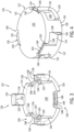
FIG. 1 is an exploded top, front, side perspective view of a pair of identical half sections of an exemplary "engaged teeth" clasp assembly according to one embodiment. In this embodiment, each identical half section includes three protruding posts having teeth on the distal ends of the posts that are engageable with the teeth on the posts of the other mating half section. -
FIG. 2 is a perspective view of the clasp assembly ofFIG. 1 in an assembled state in which the two identical half sections ofFIG. 1 have been axially brought together to create an interlocking engagement by the teeth to close the clasp. -
FIG. 3 is a top, front, side perspective view of a half section of an exemplary "teeth and cutouts" clasp assembly according to another embodiment, which does not fall into the scope of the present invention. In this embodiment, each half section includes three protruding posts from a base having teeth on the distal ends thereof that are designed for engagement with three cutouts on the base of the mating half section. -
FIG. 4 is a perspective view of a clasp assembly assembled from two identical half sections of the kind shown inFIG. 3 in which the two half sections have been axially brought together to create an interlocking engagement between the teeth and cutouts. -
FIG. 5A is a top, front, side perspective view of a half section of an exemplary "cupped surfaces" clasp assembly according to still another embodiment, which does not fall into the scope of the present invention. In this embodiment, each half section includes two posts having axially-facing concave surfaces and two posts having outwardly-facing convex surfaces. -
FIG. 5B is a cross sectional side view of the half section ofFIG. 5A taken alongline 5B-5B to better show the profile of the engagement surfaces of the half section. -
FIG. 6 is a perspective view of a clasp assembly assembled from a pair of identical half sections of the kind shown inFIGS. 5A and 5B in which the two half sections have been axially brought together to create an interlocking engagement between the axially-facing concave surfaces and the outwardly-facing convex surfaces. -
FIG. 7 is a top, front, side perspective view of a half section of an exemplary "ball and depression" clasp assembly according to yet another embodiment, which does not fall into the scope of the present invention. In this embodiment, the half section includes two posts having ball-shaped surfaces on the distal ends of the posts protruding from a base and two socket depressions on the base in which the posts and the socket depressions are staged in an alternating fashion. -
FIG. 8 is a perspective view of a clasp assembly assembled from a pair of identical half sections of the type shown inFIG. 7 , in which the two half sections have been axially brought together to create an interlocking engagement between the ball-shaped surfaces and the socket depressions. -
FIG. 9 is a top, front, side perspective view of a variation based on the half section ofFIG. 7 for a "ball and depression" type clasp assembly according to yet still another embodiment, which does not fall into the scope of the present invention. In this embodiment, the half section includes two posts having ball-shaped surfaces on the distal ends of the posts protruding from a base and two socket depressions on the base, in which the posts and the socket depressions are arranged at the corners of a square with the posts being at the corners on one half of the square and the socket depressions being at the corners on the other half of the square. Although not so illustrated, this embodiment can be assembled in a fashion similar to the one shown inFIG. 8 . - Before any embodiments of the invention are explained in detail, it is to be understood that the phraseology and terminology used herein is for the purpose of description and should not be regarded as limiting. The use of "including," "comprising," or "having" and variations thereof herein is meant to encompass the items listed thereafter and equivalents thereof as well as additional items. Unless specified or limited otherwise, the terms "mounted," "connected," "supported," and "coupled" and variations thereof are used broadly and encompass both direct and indirect mountings, connections, supports, and couplings. Further, "connected" and "coupled" are not restricted to physical or mechanical connections or couplings.
- The following discussion is presented to enable a person skilled in the art to make and use embodiments of the invention. Various modifications to the illustrated embodiments will be readily apparent to those skilled in the art, and the generic principles herein can be applied to other embodiments and applications without departing from embodiments of the invention. Thus, embodiments of the invention are not intended to be limited to embodiments shown, but are to be accorded the widest scope consistent with the principles and features disclosed herein. The figures, which are not necessarily to scale, depict selected embodiments and are not intended to limit the scope of embodiments of the invention. Skilled artisans will recognize the examples provided herein have many useful alternatives and fall within the scope of embodiments of the invention.
- Some of the discussion below describes a clasp assembly with an interlocking arrangement for a band that is formable into a loop and secured by the clasp assembly. While the discussion herein primarily discusses wristbands, the context and particulars of this discussion are presented as examples only and other embodiments are contemplated as falling within the scope of this disclosure. For example, embodiments of the disclosed clasp assemblies can include a variety of applications apart from those specifically illustrated with respect to wrist bands including but not limited to ankle bands (such as for infants), medical bands, bands for events such as concerts, straps for attachment around an object, and so forth. Still further, embodiments of the disclosed invention can be constructed from a variety of differently-shaped components that are assembled in various configurations including by use of different numbers of mating features than those depicted, only some of which embodiment will be described herein.
- As used herein, the terms "deform" and "deformable" refer to any distortion of shape or form from an initial shape or form of a component. Such distortion may be temporary in nature (as in elastic deformation) or permanent in nature (as in plastic deformation). It is contemplated that, when a component is described as being "deformed" to create engagement between clasp sections herein, that that such deformation could involve a change from an initial un-deformed state to a deformed state. Depending on the design and mode of clasp operation, the component could remain in that deformed state to create engagement or could involve a subsequent return from that deformed state back towards or to its initial un-deformed state with such return being in full or only in part to create engagement.
- Looking first at
FIG. 1, FIG. 1 illustrates an exploded view of an exemplary "toothed engagement"style clasp assembly 10 according to one embodiment. Theclasp assembly 10 is designed to be affixed to a wristband, allowing the wristband to be formed into to loop around the wrist of the person wearing the wristband using theclasp assembly 10. Such a wristband - albeit without the newly disclosed clasp assembly - can be found, for example, inU.S. Patent No. 7,240,446 to Precision Dynamics Corporation which issued on July 7, 2007 - The
clasp assembly 10 includes a pair ofhalf sections 12 that, as illustrated, are identical to one another. Eachhalf section 12 can be an integrally formed unitary structure, for example, formed by plastic injection molding. By being formed from plastic, thin walls of the parts - such as theposts 16 that will be described in greater detail below - may be elastically deformable or able to temporarily bend or deflect. - Each of the pair of
half sections 12 includes abase 14, which as illustrated can be generally disc-shaped. However, thebase 14 can be in various other forms or shapes. For example, thebase 14 could be rectangular, square, triangular or other polygonal or non-polygonal shape. The shape of the base 14 may be altered in some cases, based on the shape of the wristband to which theclasp assembly 10 is attached. - The
base 14 has a plurality ofposts 16 extending from the base 14 in a generally axial direction relative to the disc that forms thebase 14. Theseposts 16 are angularly positioned about the center of thebase 14. As illustrated, there are threeposts 16 on eachrespective base 14; however, it is contemplated that there could be two, three, or more posts on each base 14 and a similar operational effect could be achieved to that which is described herein. - Each of the
posts 16 have adistal end 18 away from thebase 14, which includes a tooth 20 (collectively, teeth). Eachtooth 20 has a wedge-like shape and radially projects from therespective post 16. As illustrated, this projection is radially outwardly relative to the central axis. As part of this projecting shape, eachtooth 20 has astop surface 22 facing back towards the base 14 from which theposts 16 extend. Eachtooth 20 also includes taperedsurfaces 24 on angular ends of therespective tooth 20, which narrow theteeth 20 towards the distal ends 18 of theposts 16. As illustrated, thetapered surfaces 24 include two sections, a bevel that is approximately 45 degrees angled relative to the central axis near thedistal end 18 and an inclined section that runs from the end of the bevel to the axial position of thestop surface 22. While illustrated as flat surfaces, the tapered surfaces 24 could also include some amount of curvature and the illustrated shapes are exemplary but not limiting. - While a particular shape and size of the
posts 16 andteeth 20 have been shown, one of ordinary skill in the art will appreciate certain variations may be made while maintaining the functionality described below. For example, the teeth do not need to be triangular wedge shaped, but might be longer arcs. Still further, while the stop surfaces of the teeth are illustrated on the radially outward side of the posts, it is contemplated that differently structure posts and teeth could present these stop surfaces on the radially inward facing side of the posts instead. - As illustrated, each of the
half sections 12 can further include acenter support 26 located between the plurality ofposts 16. In the form presented, thecenter support 26 is cylindrically shaped and located at the center of each of thehalf sections 12. Thiscenter support 26 can be connected to each of theposts 16 for a portion of their axial length to improve or control rigidity of theposts 16. Thecenter support 26 need not be cylindrical (or even present at all in many designs) and could be in the shape of pillar or rectangular prism. However, when present, the center supports 26 may also provide another stop surface (provided by axial face of the center supports 26, which may be flat) when thehalf sections 12 are joined, in addition to the stop surfaces 22, that prevents over-insertion of the two half sections together. - Looking now specifically at
FIG. 2, FIG. 2 illustrates theclasp assembly 10 ofFIG. 1 in an assembled state in which the pair ofhalf sections 12 of theclasp assembly 10 are secured to one another. Specifically, to lock or engage thesections 12 together, the plurality ofposts 16 of the pair ofhalf sections 12 are axially brought together to engage theteeth 20 of theposts 16 together. Theteeth 20 of one of thesections 12 are drawn into the space between theteeth 20 on the other one of thesections 20 and the tapered surfaces 24 on angular ends of theposts 16 on each of thehalf sections 12 contact one another. This contact between thehalf sections 12 effectuates the elastic deformation of theposts 16 to permit theteeth 20 of theposts 16 to pass by one another until thestop surface 22 of one of thehalf sections 12 axially passes thestop surface 22 of theother half section 12. Theposts 16 then deflect back or return to a non-deformed state creating an interlocking engagement between theposts 16 on each of thehalf sections 12 at the stop surfaces 22 as illustrated inFIG. 2 . - It can be observed that, for the
posts 16 of thehalf sections 12 to be in assuredly interlocking engagement, a total angular extent of the stop surfaces 22 on each of the pair ofhalf sections 12 could be made to exceed 180 degrees. By this, it is meant that each of the respective stop surfaces 22 can have an angular extent that is measured between the pair of angular ends of that particular stop surface 22 (as measured about a central axis) and that, when all of the angular extents of all the stop surfaces 22 on one of thehalf sections 12 are added together, this summed total exceeds 180 degrees. For example, in the illustrated embodiment, each of the threestop surfaces 22 may have approximately 65 degrees of angular extent, which collectively sum to approximately 195 degrees. While not an absolute requirement, this amount of angular extent necessarily creates some amount of angular overlap in joined identical half sections. Similarly, such a total summed angular extent creates some amount of overlap of the tapered surfaces 24 so the tapers almost certainly will result in less than 180 degrees of cumulative angular extent on the distal-most end of theposts 16, which will permit these distal ends to interact together during the axial insertion of thesections 12 together to create the temporary mechanical displacement of theposts 16 and theteeth 20. It will of course be appreciated that, depending on the particularly geometric form and arrangement of teeth, the stop surfaces could have less than 180 degrees of extent and the primary consideration is whether the particular geometry employed readily permits one-way engagement of the teeth without the ability to separate the halves once joined. - In the form illustrated, the interlocking engagement of the
teeth 20 at the stop surfaces 22 prevents thehalf sections 12 from separating absent mechanical destruction of at least some of the teeth or post structure. A tensile pull along an axial direction opposite the assembly direction would not pull the twohalf sections 12 apart without destroying theteeth 20 because of the non-reversible connection at the stop surfaces 22. Destroying theteeth 20 would also destroy theclasp assembly 10 and prevent the wristband from staying on the person. Accordingly, theclasp assembly 10 provides a non-reversible, secure mechanism for one time-attachment that is tamper proof. -
FIGS. 3 and 4 illustrate views of another exemplary embodiment, which does not fall into the scope of the present invention, of aclasp assembly 110 and ahalf section 112 having a "teeth and cutouts" type design. Again, theclasp assembly 110 is designed to be affixed to a wristband, allowing the wristband to be formed into a secured loop around the wrist of the person wearing the wristband using theclasp assembly 110. - The
clasp assembly 110 includes a pair ofhalf sections 112 that, as illustrated inFIG. 4 , are identical to one another. Each section can again be an integrally formed structure, for example, formed by plastic injection molding. By being formed from plastic, the parts may again be elastically deformable. - Each of the pair of
half sections 112 includes abase 114, which as illustrated can be generally disc-shaped. However, the base 114 can be in various other forms or shapes. For example, thebase 114 could be rectangular, square, triangular or other polygonal or non-polygonal shape. The shape of the base 114 may be altered in some cases or based on the shape of the wristband to which theclasp assembly 110 is to be attached. - The
base 114 has a plurality ofposts 116 extending from the base 114 in a generally axial direction relative to the disc that forms thebase 114 and about the central axis of thebase 114. As illustrated, threeposts 116 are angularly arranged around the periphery of thebase 114. However, it is contemplated that there could be two, three, or more posts on each base 114 and a similar operational effect could be achieved to that which is described herein. - Each of the
posts 116 have adistal end 118 away from thebase 114, which support and provide atooth 120. Eachtooth 120 has a wedge-like shape and radially projects inward towards the central axis from therespective post 116. As part of this projecting shape, eachtooth 120 has astop surface 122 facing back towards the base 114 from which theposts 116 extend. Thisstop surface 122 is generally parallel to the axial face ofbase 114 and/or is perpendicular to the central axis. Eachtooth 120 also includes aninclined surface 124 on the axial end of therespective tooth 120 that extends downwardly as it extends radially inwards towards that central axis until it meets thestop surface 122 to establish the tip of thetooth 120. As illustrated, since both the stop surfaces 122 and theinclined surface 124 are planar, they come together at an acute angle. - Additionally, the
base 114 has a plurality ofcutouts 130 angularly spaced about the peripheral edge of thebase 114. Each of thecutouts 130 is angularly spaced out from one another about the periphery and has an interposedpost 116 betweencutouts 130, such that as one travels around the periphery of the base 114 there is a post-cutout-post-cutout repeating pattern with a center of each feature being 60 degrees from the center of the next feature (as there are three of each feature for a total of six features). As illustrated, each of thecutouts 130 extends axially from a firstaxial surface 128 of the base 114 to a secondaxial surface 132 of thebase 114 and extends radially inward from an otherwise circular periphery of thebase 114. Thecutout 130 as illustrated is generally arcuate-shaped, with a peripheral edge jutting inwards radially towards the center of thebase 114. - In the form illustrated, each of the
cutouts 130 further have arecess 134 that extends further radially inward from the periphery than thecutout 130. Therecess 134 does not fully extend from the firstaxial surface 128 of the base 114 to the secondaxial surface 132 of thebase 114, but only fractionally therebetween. Notably, there is at least somestop surface 136 created by thisrecess 134 that faces in a generally opposite axial direction from thestop surface 122 on theteeth 120 and which has a greater length than thetooth 120 of anotheridentical half section 112 which will ultimately be received in therecess 134. - It should be appreciated that the positioning of the
posts 116 withteeth 120 and thecutouts 130 withrecesses 134 is such that, as will be illustrated inFIG. 4 , the stop surfaces 122 ofteeth 120 and the stop surfaces 136 of therecesses 134 will be engageable with one another. As such, there should be some rotational symmetry in the design of thehalf section 112 to permit this engagement and to do so at more than one angular position of thehalf sections 112 with respect to one another. - Looking now specifically at
FIG. 4, FIG. 4 illustrates theclasp assembly 110 ofFIG. 3 in an assembled state in which the pair ofhalf sections 112 of theclasp assembly 110 are secured to one another. Specifically, to lock or engage thesections 112 together, the plurality ofposts 116 of the pair ofhalf sections 112 and the plurality ofcutouts 130 withrecesses 134 are axially brought together to engage theteeth 120 of theposts 116 with therecesses 134 of the cutouts 130 (and more specifically to engage the stop surfaces 122 of theteeth 120 on theposts 116 with the stop surfaces 136 ofrecesses 134 of thecutouts 130 so that cannot be axially withdrawn from one another). To assemble twoidentical half sections 112, the axial side of thehalf sections 112 having theposts 116 are made to face one another and theposts 116 of one of thehalf sections 112 are angularly aligned with thecutouts 130 on the other of thehalf sections 112. As the twohalf sections 112 are axially drawn together (as by the action of fastening the clasp on the wristband), theinclined surface 124 of thetooth 120 comes into contact with anedge 138 of thecutout 130 between the periphery and the firstaxial face 128, thereby effectuating the elastic deformation of thepost 116 radially outward to permit thetooth 120 of thepost 116 to axially pass by theedge 138 of thecutout 130. Thestop surface 122 of thetooth 120 then continues to move axially until thestop surface 122 passes thecorresponding stop surface 136 formed by therecess 134 in thecutout 130. Theposts 116 then deflect back or return to a non-deformed state such that each of theteeth 120 of onehalf section 112 nests into the correspondingrecesses 134 of theother half section 112, thereby creating an interlocking engagement between theposts 116 on one of thehalf sections 112 with therecesses 134 in thecutouts 130 on theother half sections 112 at the stop surfaces 122 and 136. This engagement cannot be readily separated in tension without breaking theteeth 120,posts 116, and/or a wall of the base 114 forming part of therecess 134. Accordingly, theclasp assembly 110 provides a non-reversible, secure mechanism for one time-attachment. - While a particular geometry has been shown for "teeth and cutouts" type design, variations to the particular illustrated geometry are contemplated.
- For example, while a particular shape and size of the
posts 116 andteeth 120 have been shown along with those of the correspondingcutouts 130 and recesses 134, one of ordinary skill in the art will appreciate certain variations may be made while maintaining or even improving the functionality described below. For example, there could be slight undercuts on each of the stop surfaces 122 and 136 that could help to create interlocking engagement. Still further, while the arcuate length of theteeth 120 are roughly equal to the arcuate length of therecesses 134, the length of theteeth 120 could be appreciably less than the length of therecesses 134, creating a greater range of possible angular arrangements in which connection is possible. As another possibility, a regular polygonal shape may be employed such as a square or hexagon rather than a circle and that regular polygon may have alternating posts and recesses along each side or at each corner. - Still further, there could be different numbers of
posts 116 andcutouts 130 than those illustrated. For example and as illustrated, each base 114 has threecutouts 130 that correspond to the threeposts 116 andteeth 120. However, as it is contemplated that there could be two, three, or evenmore posts 116 on each base 114 with a corresponding number ofcutouts 130 and a similar operational effect could be achieved to that which is described herein. As mentioned elsewhere in this disclosure, by maintaining some rotational symmetry in the design, it is possible to have multiple orientations of alignment. Still further, by increasing the number of features, it is possible to reduce the average amount of rotation in order to come into an aligned position in which the two halves may be joined. - Further, as illustrated, the number of the
posts 116 andteeth 120 matches exactly the number of thecutouts 130 and recesses 134. However, this need not be the case. For instance, it is contemplated that there could bemore recesses 134 thanposts 116 withteeth 120. In such case, there could be various orientations of assembly between the twohalf sections 112 and some recesses may remain unoccupied even when the twohalf sections 112 are joined. - It is further considered that while, in the form presented, the
recess 134 is generally rectangular-shaped or slightly arcuate-shaped to match thecutout 130 where the recess is located in, that other geometries could be used. For example, therecess 134 could be square, triangular or other polygonal or non-polygonal shape. In such case, the teeth on the posts may be designed to have similarly shaped mating geometries. - Even beyond this, it is contemplated that the half sections could be modified such that the posts are designed to deflect radially inward (relative it the center axis of the clasp) while the recesses are formed on a centrally-facing surface to effectively reverse the positioning of the mating features and their direction of deflection.
- Turning now to
FIGS. 5A and 5B , these figures illustrate ahalf section 212 of a "cupped surfaces" style for aclasp assembly 210 can be assembled from twoidentical half sections 212 as illustrated inFIG. 6 . This embodiment does not fall into the scope of the present invention. - Again, the
clasp assembly 210 includes a pair ofhalf sections 212 that, as illustrated, are identical to one another. Eachhalf section 212 can be an integrally formed unitary structure, for example, formed by plastic injection molding. By being formed from plastic, thin walls of the parts or other sections of them may be elastically deformable. - Each of the pair of
half sections 212 includes abase 214, which as illustrated can be generally disc-shaped. However, the base 214 can be in various other forms or shapes. For example, thebase 214 could be rectangular, square, triangular or other polygonal or non-polygonal shape. The shape of the base 214 may be altered in some cases, based on the shape of the wristband to which theclasp assembly 210 is attached. - The
base 214 has a plurality ofposts 216 extending from the base 214 in a generally axial direction relative to the disc that forms the illustratedbase 214 and about the center of thebase 214. As illustrated, there are fourposts 216 on each base 214 arranged with their stems in a square on thebase 214. However, it is contemplated that there could be two or more posts on each base 214 and a similar operational effect could be achieved to that which is described herein. Based on the nature of the mating arrangement for this embodiment, it would be contemplated that there would be an even number ofposts 216 to provide the correct number of mating partners. - As illustrated, the
posts 216 have alternating male and female features around the square that are shaped to engage with theposts 216 of anotherhalf section 212. On eachhalf section 212, each of theposts 216 have adistal end 218 away from thebase 214 and aproximal end 220 near thebase 214. As illustrated, two of theposts 216 on opposing corners of the square have axially-facingconcave surfaces 222 extending between theirdistal ends 218 and the proximal ends 220. Theposts 216 with the axially-facingconcave surface 222 together form female deformable features. Further, two of theposts 216 have outwardly-facingconvex surfaces 226 extending between thedistal end 218 and theproximal end 220 and are on the two other opposing corners of the square. Theposts 216 with the outwardly-facingconvex surface 226 together form male deformable features. - Looking now specifically at
FIG. 6, FIG. 6 illustrates aclasp assembly 210 constructed from a pair ofidentical half sections 212 as illustrated inFIGS. 5A and 5B . Specifically, to temporarily lock or engage thehalf sections 212 together, the female deformable features (that is, the axially-facing concave surfaces 222) and male deformable features (that is, the outwardly-facing convex surface 226) of the pair ofhalf sections 212 are axially brought together to simultaneously engage four pairs of outwardly-facingconvex surfaces 226 with corresponding axially-facingconcave surfaces 222. As they are brought together, the outwardly-facingconvex surfaces 226 contact the axially-facingconcave surfaces 222 of the posts and effectuate the temporary elastic deformation of theposts 216 at least one of inwardly and outwardly to permit the outwardly-facingconvex surfaces 226 to pass by the distal ends 218 of the axially-facingconcave surfaces 222. To permit this initial deflection, at the distal end of the female sections there may be acutout 228 that permits entry of the leading distal edge of the slice of the male sections so that a "wedging" action may occur between the mating posts. This action continues until the outwardly-facingconvex surfaces 226 reach or approach the proximal ends 220 of the axially-facingconcave surface 222. As they reach the proximal ends 220, theposts 216 then return to a non-deformed state that creates an interlocking engagement between theposts 216 on one of thehalf sections 212 at the outwardly-facingconvex surfaces 226 and the axially-facingconcave surfaces 222 of theposts 216 on the other one of thehalf section 212 as illustrated inFIG. 6 . - The interlocking engagement of the outwardly-facing
convex surfaces 226 and the axially-facingconcave surfaces 222 prevents thehalf sections 212 from readily separating absent the application of some threshold tensile force in the direction opposite the direction of insertion described above. Unlike the first two embodiments above, this connection between the twohalf sections 212 to form theclasp assembly 210 is reversible and thehalf sections 212 can be non-destructively separated. - The male and female mating features may have various geometric qualities. For one, in some forms and as illustrated, the curvatures or profiles of the axially-facing
concave surfaces 222 and the outwardly-facingconvex surfaces 226 may be the same. The axially-facingconcave surfaces 222 and the outwardly-facingconvex surfaces 226 may be generally frustospherical surfaces (in roughly quarter sections in the case of four posts). However, to better accommodate insertion, the profile may be slightly elongated to require less deflection of theposts 216 during insertion or withdrawal. Likewise, by virtue of both material selection and profile geometries, different threshold forces can be establish for assembly and disassembly. - Similarly, to alter the deflectional properties of the
posts 216 and their attached mating components, theposts 216 and mating features may be made of different wall thickness or made solid. For example, as illustrated, the male sections are illustrated as solid wedges and the female sections are thin-walled such that the thin-walled sections are slightly more prone to deflection. Some of these geometries may also be made with respect to molding considerations and viability. - Typically, the number of female deformable features matches the number of male deformable features. However, it is contemplated that there could be more of one type of feature than the other (for example, more male features than female features or vice-versa) to permit various rotational engagements with one another. Still further, while four
posts 216 are illustrated on each post, there could be more or fewer on each. - Still further, while the axially-facing
concave surface 222 is illustrated as having a specific curvature and the outwardly-facingconvex surface 226 is illustrated as having a specific curvature that closely matches, it should be appreciated that the curvatures of each of the types of posts could have different profiles, so long as the axially-facingconcave surfaces 222 are capable of forming an interlocking engagement with the outwardly-facingconvex surface 226. - Turning now to
FIGS. 7 and 8, FIG. 7 illustrates ahalf section 312 in which a pair of thesehalf sections 312 can be assembled into an exemplary "ball and socket depression"type clasp assembly 310. This embodiment does not fall into the scope of the present invention. - The
clasp assembly 310 includes a pair ofhalf sections 312 that, as illustrated, are identical to one another. Each section is an integrally formed structure, for example, formed by plastic injection molding. By being formed from plastic, the parts may be elastically deformable. - Each of the pair of
half sections 312 includes abase 314, which as illustrated can be generally disc-shaped. However, the base 314 can be in various other forms or shapes in the various manners described above. - The
base 314 has a plurality ofposts 316 extending from the base 314 in a generally axial direction relative to the disc that forms the illustratedbase 314 and about the center of thebase 314. As illustrated, there are twoposts 316 on each base 314; however, it is contemplated that there could be two ormore posts 316 on each base 314 and a similar operational effect could be achieved to that which is described herein. - Each of the
posts 316 have a generally ball-shapedsurface 318 or head positioned away from thebase 314. The generally ball-shapedsurface 318 or head may have a radius and/or a curvature. As illustrated, the generally ball-shapedsurface 318 is generally spherical; however, other shapes may be employed. - The base 314 also has a plurality of
socket depressions 320 spaced about the center of thebase 314. Each of thesocket depressions 320 may have a radius and/or curvature that may be the same or slightly different from the radius and/or curvature of the generally ball-shapedsurfaces 318. The socket depressions 320 as illustrated can be generally circular or spherical-shaped. However, thesocket depressions 320 can be in various other forms or shapes and are contemplated as generally corresponding to the profile of the ball-shapedsurfaces 318 of theposts 316. It is also contemplated that the shape of the socket need not exactly match the head of the post, but that they should correspond in form so as to permit the snap-type engagement with one another described below. - One or both of the ball-shaped
surface 318 and thesocket depressions 320 are able to deform slightly due to the elasticity of the plastic material to create individual interlocking engagement between one of the heads and a corresponding one of the sockets. Accordingly, thedepressions 320 should be more than half of the volume of the hypothetical ball being inserted into it so that some amount of "capture" or interlocking occurs between the head or ball and socket. - Looking now at
FIG. 8, FIG. 8 illustrates theclasp assembly 310 ofFIG. 7 in an assembled state in which the pair ofhalf sections 312 of theclasp assembly 310 are secured to one another. Specifically, to lock or engage thesections 312 together, the plurality ofposts 316 with ball-shapedsurfaces 318 and thesocket depressions 320 of the pair ofhalf sections 312 are axially brought together to engage the ball-shapedsurfaces 318 or heads of theposts 316 with thesocket depressions 320 on thebase 314. During insertion, the ball-shapedsurfaces 318 on one of thehalf sections 312 contact thesocket depressions 320 on thebase 314 of theother half section 312. This contact between thehalf sections 312 effectuates the elastic deformation of ball-shapedsurfaces 318 and/orsocket depressions 320 to temporarily and elastically crush ball-shapedsurfaces 318 and/or expand thesocket depression 320 to permit entry of the head into the socket. Upon sufficient insertion, the ball-shapedsurfaces 318 "snap" into thesocket depressions 320 and both return towards their original profiles. In the case of the illustrated embodiment, four such interlocking snap connections are made of this nature in near simultaneous fashion. - The interlocking engagement between the ball-shaped
surfaces 318 and thesocket depressions 320 prevents thehalf sections 312 from separating absent the application of a tensile force above a threshold force in the axial direction counter to the direction of insertion. Like the third embodiment, but unlike the first two embodiments, the heads can be removed from the sockets non-destructively and so the connection of theclasp assembly 310 is reversible. - As illustrated, there are two
socket depressions 320 and two ball-shapedsurfaces 320 on each base 314. However, it is contemplated that there could be two ormore socket depressions 320 and two or more ball-shapedsurfaces 318 on each base 314 and a similar operational effect could be achieved to that which is described herein. While illustrated as an alternating arrangement between thesocket depressions 320 and theposts 316 with ball-shapedsurfaces 318, theposts 316 with ball-shapedsurfaces 318 and thesocket depressions 320 may be arranged in other fashions. For example and in a non-limiting exemplary arrangement shown inFIG. 9 depicting analternative half section 412, the posts 416 with ball-shapedsurfaces 418 and thesocket depressions 420 may be arranged at the corners of a square. In this form illustrated inFIG. 9 , the posts 416 with ball-shapedsurfaces 418 are at the corners on one-half of the square and thesocket depressions 420 are at the corners on the other half of the square. - Generally speaking, discrete rotational symmetry is used in all of these embodiments to construct designs for each half section so that identical half sections can be used with one another. The half section is designed to couple with itself using symmetry constructs. The discrete rotational symmetry (360°/n), maximum rotation to close, and average rotation to close of 1 to 7 coupling mechanisms are shown in the table below:
Table 1 Number of coupling mechanisms Discrete rotational symmetry (360°/n) Maximum rotation to close Average rotation to close 1 n = 1, 360° 360° 180° 2 n = 2, 180° 180° 90° 3 n = 3, 120° 120° 60° 4 n = 4, 90° 90° 45° 5 n = 5, 72° 72° 36° 6 n = 6, 60° 60° 30° 7 


360 n = 360, 1° 1° 0.5° - Rotational symmetry for an object of order n occurs when rotating the object by 360°/n does not change the object. Taking common joints and fractionalizing them or copying individual joints many times allows for the creation of clasps that both symmetrical and interlocking. In this way, the classic male/female designs for coupling can be obfuscated. The higher degrees of symmetry also benefit the closing of the clasps by requiring less rotation (maximum or average) to align the half sections for closure. Those skilled in the art of plastic injection molding and additive manufacturing techniques will understand that this complexity for small couplings can be extremely hard to engineer and that there are diminishing gains as n approaches 20 and beyond. Preferably, the discrete rotational symmetry of the half sections for the assembly disclosed are between 2 and 20, more preferably between 3 and 10 for the greatest combination of mechanical strength, manufacturing simplicity and usability.
- As noted above, it should be appreciated that various other modifications and variations to the preferred embodiments can be made within the scope of the invention. Therefore, the invention should not be limited to the described embodiments. To ascertain the full scope of the invention, the following claims should be referenced.
Claims (5)
- A clasp assembly (10) comprising:
a pair of identical half sections (12) configured to be coupled together, in which each half section (12) comprises one or more deformable features that are designed to deform during closure to create an interlocking engagement between each half section (12) characterized in that the one or more deformable features are posts (16) extending axially from a base (14) of the respective half section (12), each of the posts (16) having a tooth (20) with a wedge-like shape, the respective tooth (20) provided at the distal end (18) away from the base (14) and radially projects from each of the posts (16), with the tooth (20) having a stop surface (22) facing the base (14); wherein each of the pair of identical half sections (12) has discrete rotational symmetry; wherein, after interlocking engagement, the pair of identical half sections (12) are not completely axially separable without permanent mechanical destruction of the one or more deformable features, wherein the interlocking engagement is created between the teeth (20) at the stop surfaces (22), wherein the teeth (20) further include tapered surfaces (24) on angular ends thereof that narrow as the teeth (20) extend towards the distal end (18) of the respective post (16). - The clasp assembly (10) of claim 1, wherein, when the posts (16) of the pair of half sections (12) are axially brought together to engage the teeth (20) of the posts (16) together, the tapered surfaces (24) on angular ends of the posts (16) on each of the half sections (12) are configured to contact one another and to effectuate the elastic deformation of the posts (16) to permit the teeth (20) of the posts (16) to pass by one another until the stop surfaces (22) of one of the half sections has axially passed the stop surfaces (22) of the other one of the half sections (12), and the posts (16) are configured to return to a non-deformed state to create an interlocking engagement between the posts (16) on each of the half sections (12) at the stop surfaces (20).
- The clasp assembly (10) of claim 1, wherein each of the stop surfaces (22) have a corresponding angular extent between angular ends of the respective stop surface (22) and wherein the total summed amount of the angular extents of the plurality of stop surfaces (22) on one of the half sections (12) exceeds 180 degrees to create angular overlap between the stop surfaces (22) of the pair of half sections (12) with one another when the posts (16) of the half sections (12) are brought together in interlocking engagement.
- The clasp assembly (10) of claim 1, wherein the pair of half sections (12) are each an integrally formed plastic component.
- A wristband comprising a band formable into a loop including the clasp assembly (10) of claim 1.
Applications Claiming Priority (2)
| Application Number | Priority Date | Filing Date | Title |
|---|---|---|---|
| US201962844264P | 2019-05-07 | 2019-05-07 | |
| PCT/US2020/031619 WO2020227371A1 (en) | 2019-05-07 | 2020-05-06 | Clasp assembly |
Publications (4)
| Publication Number | Publication Date |
|---|---|
| EP3965606A1 EP3965606A1 (en) | 2022-03-16 |
| EP3965606A4 EP3965606A4 (en) | 2023-01-18 |
| EP3965606C0 EP3965606C0 (en) | 2024-12-25 |
| EP3965606B1 true EP3965606B1 (en) | 2024-12-25 |
Family
ID=73046168
Family Applications (1)
| Application Number | Title | Priority Date | Filing Date |
|---|---|---|---|
| EP20802099.0A Active EP3965606B1 (en) | 2019-05-07 | 2020-05-06 | Clasp assembly |
Country Status (3)
| Country | Link |
|---|---|
| US (1) | US11419392B2 (en) |
| EP (1) | EP3965606B1 (en) |
| WO (1) | WO2020227371A1 (en) |
Families Citing this family (5)
| Publication number | Priority date | Publication date | Assignee | Title |
|---|---|---|---|---|
| USD948869S1 (en) * | 2019-11-08 | 2022-04-19 | Sohhee Trading Co., Ltd. | Bag fastener |
| CN115460999A (en) | 2020-03-04 | 2022-12-09 | 施菲姆德控股有限责任公司 | Thrombus removal systems and related methods |
| CN113057423B (en) * | 2021-03-29 | 2023-01-24 | 歌尔股份有限公司 | Watch buckle structure and wearable device with same |
| US12599397B2 (en) | 2021-05-19 | 2026-04-14 | Shifamed Holdings, Llc | Thrombus removal systems and associated methods |
| WO2025080978A1 (en) * | 2023-10-11 | 2025-04-17 | Shifamed Holdings, Llc | Loading tool for medical device with expandable distal end |
Family Cites Families (26)
| Publication number | Priority date | Publication date | Assignee | Title |
|---|---|---|---|---|
| US424795A (en) * | 1890-04-01 | Glove-fastener | ||
| US2163016A (en) * | 1937-08-16 | 1939-06-20 | Keyes Davis Company | Marking band |
| US2235168A (en) * | 1940-04-05 | 1941-03-18 | Harold J Reiter | Snap fastener |
| US3141321A (en) * | 1963-04-12 | 1964-07-21 | Scovill Manufacturing Co | Key retaining member |
| GB1022435A (en) | 1963-11-12 | 1966-03-16 | Aackersberg Mortensen | Plastics fastening member for snap fasteners |
| US3416200A (en) * | 1967-03-22 | 1968-12-17 | Scovill Manufacturing Co | Permanently locking snap fastener |
| US4161806A (en) * | 1977-03-24 | 1979-07-24 | Bonnie Enterprises, Inc. | Snap fastener |
| US4272869A (en) * | 1979-09-07 | 1981-06-16 | Willner Nancy J | Unitized attachment device |
| GB8415713D0 (en) * | 1984-06-20 | 1984-07-25 | Lam Kam Yau | Button |
| US4982480A (en) * | 1987-05-15 | 1991-01-08 | Yoshida Kogyo, K.K. | Pair of snappingly engageable members |
| US4819309A (en) * | 1987-08-27 | 1989-04-11 | Minnesota Mining And Manufacturing Company | Fastener with parts having projecting engaging portions |
| US4913174A (en) * | 1987-12-04 | 1990-04-03 | Cusenza Partnership | Hair fastener |
| EP0349175B1 (en) * | 1988-06-25 | 1994-03-02 | Peter Maxwell Robson | Profiled fastener |
| US5224247A (en) * | 1988-10-14 | 1993-07-06 | Harmony Fastening Systems, Inc. | Strap fastener |
| US6363584B1 (en) * | 2000-01-20 | 2002-04-02 | George Gero | Cuff link with changeable element |
| US20020029444A1 (en) * | 2000-09-07 | 2002-03-14 | Lyle Michael A. | Snap fastener |
| JP2002191410A (en) * | 2000-12-26 | 2002-07-09 | Yamato Shoji Nire:Kk | Clasp |
| US6606767B2 (en) * | 2001-07-09 | 2003-08-19 | Sheung Chung Wong | Magnetic strap fastener |
| GB2390112B (en) | 2002-06-26 | 2005-09-07 | Michael John Stubbs | Snap fastener for use with fabrics |
| US20060010650A1 (en) * | 2004-07-16 | 2006-01-19 | French Lon G | Double hinge apparatus |
| US7240446B2 (en) | 2005-04-18 | 2007-07-10 | Precision Dynamics Corporation | Identification bracelet with sealable window |
| US8683660B2 (en) * | 2009-06-10 | 2014-04-01 | Ykk Corporation | Snap button |
| US8490257B2 (en) * | 2010-03-18 | 2013-07-23 | Paige Cameron | Integrated logo fastening system |
| US10857476B2 (en) * | 2016-09-28 | 2020-12-08 | Bodak Blocks Limited | Building block and building block assemblies |
| US10111500B2 (en) * | 2016-11-08 | 2018-10-30 | Brian Lambert | Self-aligning, quick connect and disconnect magnetic end connectors |
| US20210106100A1 (en) * | 2019-10-11 | 2021-04-15 | Lorenzo Marrone | Cuff Loop Fastening Devices and Methods of Using |
-
2020
- 2020-05-06 EP EP20802099.0A patent/EP3965606B1/en active Active
- 2020-05-06 US US16/868,156 patent/US11419392B2/en active Active
- 2020-05-06 WO PCT/US2020/031619 patent/WO2020227371A1/en not_active Ceased
Also Published As
| Publication number | Publication date |
|---|---|
| WO2020227371A1 (en) | 2020-11-12 |
| EP3965606A1 (en) | 2022-03-16 |
| EP3965606A4 (en) | 2023-01-18 |
| US11419392B2 (en) | 2022-08-23 |
| US20200352286A1 (en) | 2020-11-12 |
| EP3965606C0 (en) | 2024-12-25 |
Similar Documents
| Publication | Publication Date | Title |
|---|---|---|
| US11419392B2 (en) | Clasp assembly | |
| US11344391B2 (en) | Dental models and related methods | |
| JP6453949B2 (en) | Exterior subassemblies for watches or watches or jewelry | |
| EP0158030B1 (en) | Medical instrument | |
| US6665909B2 (en) | Low-profile mounting clip for personal device | |
| CN102325475B (en) | button | |
| US11462893B2 (en) | Line-guiding device | |
| EP2457535B1 (en) | Archwire bracket for orthodontics | |
| JP6625376B2 (en) | Fasteners, intervertebral interbody systems including fasteners, and methods | |
| CA2472700A1 (en) | Implantable band with attachment mechanism having dissimilar material properties | |
| TWI478742B (en) | Coupling arrangement | |
| EP3788968B1 (en) | Self-retaining nail to insertion handle interface | |
| CN108065997A (en) | The component of modular bone plate and modular bone plate | |
| US12171942B2 (en) | Respiratory mask system | |
| US20140045137A1 (en) | Orthodontic archwire bracket | |
| US12202182B2 (en) | Positioning device with multi-directional lock | |
| CN100362393C (en) | elastic hinge | |
| CN106102851A (en) | Model | |
| US20030044746A1 (en) | User removable fasteners | |
| CN107656432B (en) | For clock and watch or the sub-component of the external component of Jewelry Accessories | |
| KR102709268B1 (en) | Dental anchoring system for fixing prosthetics | |
| TWI712394B (en) | Combined assembly for dentures | |
| US1200223A (en) | Snap-fastener. | |
| TWM538785U (en) | Dental implant assembly and drill base thereof | |
| JP2004308767A (en) | Torque limiter |
Legal Events
| Date | Code | Title | Description |
|---|---|---|---|
| STAA | Information on the status of an ep patent application or granted ep patent |
Free format text: STATUS: THE INTERNATIONAL PUBLICATION HAS BEEN MADE |
|
| PUAI | Public reference made under article 153(3) epc to a published international application that has entered the european phase |
Free format text: ORIGINAL CODE: 0009012 |
|
| STAA | Information on the status of an ep patent application or granted ep patent |
Free format text: STATUS: REQUEST FOR EXAMINATION WAS MADE |
|
| 17P | Request for examination filed |
Effective date: 20211118 |
|
| AK | Designated contracting states |
Kind code of ref document: A1 Designated state(s): AL AT BE BG CH CY CZ DE DK EE ES FI FR GB GR HR HU IE IS IT LI LT LU LV MC MK MT NL NO PL PT RO RS SE SI SK SM TR |
|
| DAV | Request for validation of the european patent (deleted) | ||
| DAX | Request for extension of the european patent (deleted) | ||
| REG | Reference to a national code |
Ref country code: DE Ref legal event code: R079 Free format text: PREVIOUS MAIN CLASS: A44B0017000000 Ipc: A44C0005200000 Ref country code: DE Ref legal event code: R079 Ref document number: 602020043751 Country of ref document: DE Free format text: PREVIOUS MAIN CLASS: A44B0017000000 Ipc: A44C0005200000 |
|
| A4 | Supplementary search report drawn up and despatched |
Effective date: 20221216 |
|
| RIC1 | Information provided on ipc code assigned before grant |
Ipc: A44C 5/20 20060101AFI20221212BHEP |
|
| STAA | Information on the status of an ep patent application or granted ep patent |
Free format text: STATUS: EXAMINATION IS IN PROGRESS |
|
| 17Q | First examination report despatched |
Effective date: 20230511 |
|
| GRAP | Despatch of communication of intention to grant a patent |
Free format text: ORIGINAL CODE: EPIDOSNIGR1 |
|
| STAA | Information on the status of an ep patent application or granted ep patent |
Free format text: STATUS: GRANT OF PATENT IS INTENDED |
|
| INTG | Intention to grant announced |
Effective date: 20240816 |
|
| GRAS | Grant fee paid |
Free format text: ORIGINAL CODE: EPIDOSNIGR3 |
|
| GRAA | (expected) grant |
Free format text: ORIGINAL CODE: 0009210 |
|
| STAA | Information on the status of an ep patent application or granted ep patent |
Free format text: STATUS: THE PATENT HAS BEEN GRANTED |
|
| AK | Designated contracting states |
Kind code of ref document: B1 Designated state(s): AL AT BE BG CH CY CZ DE DK EE ES FI FR GB GR HR HU IE IS IT LI LT LU LV MC MK MT NL NO PL PT RO RS SE SI SK SM TR |
|
| REG | Reference to a national code |
Ref country code: GB Ref legal event code: FG4D |
|
| REG | Reference to a national code |
Ref country code: CH Ref legal event code: EP |
|
| REG | Reference to a national code |
Ref country code: DE Ref legal event code: R096 Ref document number: 602020043751 Country of ref document: DE |
|
| REG | Reference to a national code |
Ref country code: IE Ref legal event code: FG4D |
|
| U01 | Request for unitary effect filed |
Effective date: 20250123 |
|
| U07 | Unitary effect registered |
Designated state(s): AT BE BG DE DK EE FI FR IT LT LU LV MT NL PT RO SE SI Effective date: 20250130 |
|
| PG25 | Lapsed in a contracting state [announced via postgrant information from national office to epo] |
Ref country code: HR Free format text: LAPSE BECAUSE OF FAILURE TO SUBMIT A TRANSLATION OF THE DESCRIPTION OR TO PAY THE FEE WITHIN THE PRESCRIBED TIME-LIMIT Effective date: 20241225 |
|
| PG25 | Lapsed in a contracting state [announced via postgrant information from national office to epo] |
Ref country code: NO Free format text: LAPSE BECAUSE OF FAILURE TO SUBMIT A TRANSLATION OF THE DESCRIPTION OR TO PAY THE FEE WITHIN THE PRESCRIBED TIME-LIMIT Effective date: 20250325 |
|
| PG25 | Lapsed in a contracting state [announced via postgrant information from national office to epo] |
Ref country code: GR Free format text: LAPSE BECAUSE OF FAILURE TO SUBMIT A TRANSLATION OF THE DESCRIPTION OR TO PAY THE FEE WITHIN THE PRESCRIBED TIME-LIMIT Effective date: 20250326 |
|
| PG25 | Lapsed in a contracting state [announced via postgrant information from national office to epo] |
Ref country code: RS Free format text: LAPSE BECAUSE OF FAILURE TO SUBMIT A TRANSLATION OF THE DESCRIPTION OR TO PAY THE FEE WITHIN THE PRESCRIBED TIME-LIMIT Effective date: 20250325 |
|
| U20 | Renewal fee for the european patent with unitary effect paid |
Year of fee payment: 6 Effective date: 20250526 |
|
| PG25 | Lapsed in a contracting state [announced via postgrant information from national office to epo] |
Ref country code: SM Free format text: LAPSE BECAUSE OF FAILURE TO SUBMIT A TRANSLATION OF THE DESCRIPTION OR TO PAY THE FEE WITHIN THE PRESCRIBED TIME-LIMIT Effective date: 20241225 |
|
| PG25 | Lapsed in a contracting state [announced via postgrant information from national office to epo] |
Ref country code: PL Free format text: LAPSE BECAUSE OF FAILURE TO SUBMIT A TRANSLATION OF THE DESCRIPTION OR TO PAY THE FEE WITHIN THE PRESCRIBED TIME-LIMIT Effective date: 20241225 |
|
| PG25 | Lapsed in a contracting state [announced via postgrant information from national office to epo] |
Ref country code: ES Free format text: LAPSE BECAUSE OF FAILURE TO SUBMIT A TRANSLATION OF THE DESCRIPTION OR TO PAY THE FEE WITHIN THE PRESCRIBED TIME-LIMIT Effective date: 20241225 |
|
| PG25 | Lapsed in a contracting state [announced via postgrant information from national office to epo] |
Ref country code: IS Free format text: LAPSE BECAUSE OF FAILURE TO SUBMIT A TRANSLATION OF THE DESCRIPTION OR TO PAY THE FEE WITHIN THE PRESCRIBED TIME-LIMIT Effective date: 20250425 |
|
| PG25 | Lapsed in a contracting state [announced via postgrant information from national office to epo] |
Ref country code: SK Free format text: LAPSE BECAUSE OF FAILURE TO SUBMIT A TRANSLATION OF THE DESCRIPTION OR TO PAY THE FEE WITHIN THE PRESCRIBED TIME-LIMIT Effective date: 20241225 |
|
| PG25 | Lapsed in a contracting state [announced via postgrant information from national office to epo] |
Ref country code: CZ Free format text: LAPSE BECAUSE OF FAILURE TO SUBMIT A TRANSLATION OF THE DESCRIPTION OR TO PAY THE FEE WITHIN THE PRESCRIBED TIME-LIMIT Effective date: 20241225 |
|
| PLBE | No opposition filed within time limit |
Free format text: ORIGINAL CODE: 0009261 |
|
| STAA | Information on the status of an ep patent application or granted ep patent |
Free format text: STATUS: NO OPPOSITION FILED WITHIN TIME LIMIT |
|
| REG | Reference to a national code |
Ref country code: CH Ref legal event code: L10 Free format text: ST27 STATUS EVENT CODE: U-0-0-L10-L00 (AS PROVIDED BY THE NATIONAL OFFICE) Effective date: 20251105 |
|
| 26N | No opposition filed |
Effective date: 20250926 |
|
| REG | Reference to a national code |
Ref country code: CH Ref legal event code: H13 Free format text: ST27 STATUS EVENT CODE: U-0-0-H10-H13 (AS PROVIDED BY THE NATIONAL OFFICE) Effective date: 20251223 |
|
| PG25 | Lapsed in a contracting state [announced via postgrant information from national office to epo] |
Ref country code: CH Free format text: LAPSE BECAUSE OF NON-PAYMENT OF DUE FEES Effective date: 20250531 |
|
| PG25 | Lapsed in a contracting state [announced via postgrant information from national office to epo] |
Ref country code: MC Free format text: LAPSE BECAUSE OF FAILURE TO SUBMIT A TRANSLATION OF THE DESCRIPTION OR TO PAY THE FEE WITHIN THE PRESCRIBED TIME-LIMIT Effective date: 20241225 |
|
| PGFP | Annual fee paid to national office [announced via postgrant information from national office to epo] |
Ref country code: GB Payment date: 20260304 Year of fee payment: 7 |
|
| PG25 | Lapsed in a contracting state [announced via postgrant information from national office to epo] |
Ref country code: IE Free format text: LAPSE BECAUSE OF NON-PAYMENT OF DUE FEES Effective date: 20250506 |