EP3965510A1 - Konfigurationsaktivierungs-/deaktivierungsverfahren, netzwerkgerät und endgerät - Google Patents
Konfigurationsaktivierungs-/deaktivierungsverfahren, netzwerkgerät und endgerät Download PDFInfo
- Publication number
- EP3965510A1 EP3965510A1 EP20798472.5A EP20798472A EP3965510A1 EP 3965510 A1 EP3965510 A1 EP 3965510A1 EP 20798472 A EP20798472 A EP 20798472A EP 3965510 A1 EP3965510 A1 EP 3965510A1
- Authority
- EP
- European Patent Office
- Prior art keywords
- configuration
- activation
- information
- multiple transmission
- field
- Prior art date
- Legal status (The legal status is an assumption and is not a legal conclusion. Google has not performed a legal analysis and makes no representation as to the accuracy of the status listed.)
- Granted
Links
Images

Classifications
-
- H—ELECTRICITY
- H04—ELECTRIC COMMUNICATION TECHNIQUE
- H04W—WIRELESS COMMUNICATION NETWORKS
- H04W72/00—Local resource management
- H04W72/20—Control channels or signalling for resource management
- H04W72/23—Control channels or signalling for resource management in the downlink direction of a wireless link, i.e. towards a terminal
- H04W72/232—Control channels or signalling for resource management in the downlink direction of a wireless link, i.e. towards a terminal the control data signalling from the physical layer, e.g. DCI signalling
-
- H—ELECTRICITY
- H04—ELECTRIC COMMUNICATION TECHNIQUE
- H04W—WIRELESS COMMUNICATION NETWORKS
- H04W72/00—Local resource management
- H04W72/20—Control channels or signalling for resource management
- H04W72/23—Control channels or signalling for resource management in the downlink direction of a wireless link, i.e. towards a terminal
-
- H—ELECTRICITY
- H04—ELECTRIC COMMUNICATION TECHNIQUE
- H04L—TRANSMISSION OF DIGITAL INFORMATION, e.g. TELEGRAPHIC COMMUNICATION
- H04L1/00—Arrangements for detecting or preventing errors in the information received
- H04L1/12—Arrangements for detecting or preventing errors in the information received by using return channel
- H04L1/16—Arrangements for detecting or preventing errors in the information received by using return channel in which the return channel carries supervisory signals, e.g. repetition request signals
- H04L1/18—Automatic repetition systems, e.g. Van Duuren systems
- H04L1/1812—Hybrid protocols; Hybrid automatic repeat request [HARQ]
-
- H—ELECTRICITY
- H04—ELECTRIC COMMUNICATION TECHNIQUE
- H04L—TRANSMISSION OF DIGITAL INFORMATION, e.g. TELEGRAPHIC COMMUNICATION
- H04L5/00—Arrangements affording multiple use of the transmission path
- H04L5/003—Arrangements for allocating sub-channels of the transmission path
- H04L5/0048—Allocation of pilot signals, i.e. of signals known to the receiver
- H04L5/0051—Allocation of pilot signals, i.e. of signals known to the receiver of dedicated pilots, i.e. pilots destined for a single user or terminal
-
- H—ELECTRICITY
- H04—ELECTRIC COMMUNICATION TECHNIQUE
- H04L—TRANSMISSION OF DIGITAL INFORMATION, e.g. TELEGRAPHIC COMMUNICATION
- H04L5/00—Arrangements affording multiple use of the transmission path
- H04L5/003—Arrangements for allocating sub-channels of the transmission path
- H04L5/0053—Allocation of signalling, i.e. of overhead other than pilot signals
-
- H—ELECTRICITY
- H04—ELECTRIC COMMUNICATION TECHNIQUE
- H04L—TRANSMISSION OF DIGITAL INFORMATION, e.g. TELEGRAPHIC COMMUNICATION
- H04L5/00—Arrangements affording multiple use of the transmission path
- H04L5/0091—Signalling for the administration of the divided path, e.g. signalling of configuration information
- H04L5/0096—Indication of changes in allocation
-
- H—ELECTRICITY
- H04—ELECTRIC COMMUNICATION TECHNIQUE
- H04W—WIRELESS COMMUNICATION NETWORKS
- H04W72/00—Local resource management
- H04W72/04—Wireless resource allocation
- H04W72/044—Wireless resource allocation based on the type of the allocated resource
- H04W72/0446—Resources in time domain, e.g. slots or frames
-
- H—ELECTRICITY
- H04—ELECTRIC COMMUNICATION TECHNIQUE
- H04W—WIRELESS COMMUNICATION NETWORKS
- H04W72/00—Local resource management
- H04W72/04—Wireless resource allocation
- H04W72/044—Wireless resource allocation based on the type of the allocated resource
- H04W72/0453—Resources in frequency domain, e.g. a carrier in FDMA
-
- H—ELECTRICITY
- H04—ELECTRIC COMMUNICATION TECHNIQUE
- H04W—WIRELESS COMMUNICATION NETWORKS
- H04W72/00—Local resource management
- H04W72/20—Control channels or signalling for resource management
- H04W72/23—Control channels or signalling for resource management in the downlink direction of a wireless link, i.e. towards a terminal
- H04W72/231—Control channels or signalling for resource management in the downlink direction of a wireless link, i.e. towards a terminal the control data signalling from the layers above the physical layer, e.g. RRC or MAC-CE signalling
-
- H—ELECTRICITY
- H04—ELECTRIC COMMUNICATION TECHNIQUE
- H04W—WIRELESS COMMUNICATION NETWORKS
- H04W76/00—Connection management
- H04W76/20—Manipulation of established connections
- H04W76/27—Transitions between radio resource control [RRC] states
Definitions
- the present disclosure relates to the field of communication technology, in particular to a configuration activation/deactivation method, a network device, and a terminal.
- 5G NR 5 th generation new radio access technology
- 5G NR 5 th generation new radio access technology
- URLLC Ultra Reliable Low Latency Communications
- a configuration period is defined in the uplink grant-free retransmission scheme, at the same time, it is required that after the terminal starts transmission in a period, the transmission must end within the period and cannot exceed the period. This will cause the actual quantity of retransmissions to be less than the configured quantity of retransmissions, which affects reliability.
- multiple parallel configurations are used, and the configurations offset from each other in terms of the start position of the period, that is, a multi-configuration solution is used.
- the configuration needs to be activated through downlink control information (DCI).
- DCI downlink control information
- Activating one configuration through one DCI causes a large overhead for a physical downlink control channel (PDCCH).
- PDCCH physical downlink control channel
- PDCCH resources are insufficient, the configuration cannot be activated until PDCCH resources are available, thus a latency is introduced.
- the present disclosure provides a configuration activation/deactivation method, a network device, and a terminal, so as to solve the problems of large overhead and high latency when multiple transmission configurations are activated.
- some embodiments of the present disclosure provide an configuration activation/deactivation method, including:
- the multiple transmission configurations are transmission configurations associated with a first search space (SS) or a first control resource set (CORESET) in configuration information of the activation/deactivation information;
- the first SS is an SS where the activation/deactivation information is detected, and the first CORESET is a CORESET where the activation/deactivation information is detected.
- the activation information used for indicating activation of the multiple transmission configurations includes a second field, and the second field is used for indicating activation of second configuration information that is different among the multiple transmission configurations.
- the second configuration information includes at least one of the following:
- the first field or the second field or a verification field in the activation/deactivation information is at least one of following items in downlink control information (DCI):
- some embodiments of the present disclosure further provide a network device, including: a transceiver, a memory, a processor, and a program stored in the memory and configured to be executed by the processor, wherein, the processor is configured to execute the program to implement following steps:
- the multiple transmission configurations are transmission configurations associated with a first search space (SS) or the a first control resource set (CORESET) in configuration information of the activation/deactivation information;
- the first SS is an SS where the activation/deactivation information is detected, and the first CORESET is a CORESET where the activation/deactivation information is detected.
- the activation information used for indicating activation of the multiple transmission configurations includes a second field, and the second field is used for indicating activation of a second configuration information that is different among the multiple transmission configurations.
- the second configuration information includes at least one of the following:
- the first field or the second field or a verification field in the activation/deactivation information is at least one of following items in downlink control information DCI:
- some embodiments of the present disclosure further provide a network device, including:
- some embodiments of the present disclosure further provide an configuration activation/deactivation method, including:
- the multiple transmission configurations are transmission configurations associated with a first search space (SS) or a first control resource set (CORESET) in configuration information of the activation/deactivation information;
- the first SS is an SS where the activation/deactivation information is detected, and the first CORESET is a CORESET where the activation/deactivation information is detected.
- the activation information used for indicating activation of the multiple transmission configurations includes a second field, and the second field is used for indicating activation of second configuration information that is different among the multiple transmission configurations.
- the second configuration information includes at least one of the following:
- the first field or the second field or a verification field in the activation/deactivation information is at least one of following items in downlink control information DCI:
- some embodiments of the present disclosure further provide a terminal, including: a transceiver, a memory, a processor, and a program stored in the memory and configured to be executed by the processor, wherein the processor is configured to execute the program to implement following steps:
- the multiple transmission configurations are transmission configurations associated with a first search space (SS) or a first control resource set (CORESET) in configuration information of the activation/deactivation information;
- the first SS is an SS where the activation/deactivation information is detected, and the first CORESET is a CORESET where the activation/deactivation information is detected.
- the activation information used for indicating activation of the multiple transmission configurations includes a second field, and the second field is used for indicating activation of second configuration information that is different among the multiple transmission configurations.
- the second configuration information includes at least one of the following:
- the first field or the second field or a verification field in the activation/deactivation information is at least one of following items in downlink control information DCI:
- some embodiments of the present disclosure further provide a terminal, including:
- some embodiments of the present disclosure further provide a computer-readable storage medium storing thereon a computer program, the computer program is configured to be executed by a processor to implement the steps of the above-mentioned configuration activation/deactivation methods.
- activation/deactivation information for indicating activation/deactivation of multiple transmission configurations is transmitted to a terminal; wherein the multiple transmission configurations are associated with the configuration information of the activation/deactivation information, or a first field of the activation/deactivation information is used for indicating activation/deactivation of first configuration information that is same among the multiple transmission configurations, thus multiple transmission configurations can be activated by a single piece of activation/deactivation information, and the problem of large overhead and high latency when multiple transmission configurations are activated is solved.
- sequence number of the following processes does not imply the order of execution.
- the execution order of each process should be determined by its function and inherent logic.
- sequence number of the following processes does not constitute any limitation on the implementation process of the embodiments of the present disclosure.
- system and “network” in the present disclosure are often used interchangeably in the present disclosure.
- B corresponding to A means that B is associated with A, and B can be determined according to A.
- determining B according to A does not mean that B is determined only according to A, rather, B can be determined according to A and/or other information.
- the form of the access network is not limited, and may include a macro base station, pico base station, Node B (the nomenclature of a 3G mobile base station), evolved Node B (eNB), femto eNB or Home eNode B or Home eNB or HeNB, relay station, access point, remote radio unit (RRU), remote radio head (RRH) or the like.
- Node B the nomenclature of a 3G mobile base station
- eNB evolved Node B
- relay station access point
- RRU remote radio unit
- RRH remote radio head
- the user terminal can be a mobile phone (or cell phone), or other equipment capable of transmitting or receiving wireless signals, including user equipment, personal digital assistant (PDA), wireless modem, wireless communication device, handheld device, laptop computer, cordless phone, wireless local loop (WLL) station, customer premise equipment (CPE) that can convert mobile signals into wireless fidelity (WiFi) signals, or mobile smart hotspot, smart home appliance, or other devices that can spontaneously communicate with the mobile communication network without human operation.
- PDA personal digital assistant
- WiFi wireless fidelity
- smart home appliance smart home appliance
- embodiments of the present disclosure provide an information transmission method, which solves the problems in the related art that activation of configuration when information is transmitted results in large overhead and high latency.
- embodiments of the present disclosure provide an configuration activation/deactivation method, which specifically includes: step 11: transmitting, to a terminal, activation/deactivation information for indicating activation/deactivation of multiple transmission configurations.
- the multiple transmission configurations are associated with configuration information of the activation/deactivation information, or a first field of the activation/deactivation information is used for indicating activation/deactivation of first configuration information that is same among the multiple transmission configurations.
- the transmission configuration is used for uplink data transmission or downlink data transmission.
- the activation/deactivation information can be uplink control information or downlink control information. That is, the configuration activation/deactivation method in some embodiments of the present disclosure can be applied to activation/deactivation of the transmission configuration of uplink data transmission, and it can also be applied to activation/deactivation of the transmission configuration of downlink data transmission.
- activation/deactivation information for indicating activation/deactivation of multiple transmission configurations is transmitted to a terminal; wherein the multiple transmission configurations are associated with the configuration information of the activation/deactivation information, or a first field of the activation/deactivation information is used for indicating activation/deactivation of first configuration information that is same among the multiple transmission configurations, thus multiple transmission configurations can be activated by a single piece of activation/deactivation information, and the problem of large overhead and high latency when multiple transmission configurations are activated is solved.
- a first field is used for indicating activation of first configuration information that is same among the multiple transmission configurations.
- the first field may be a newly added field in DCI, or may be one of the following items in DCI:
- Manner 1 the first field is used for indicating a bitmap of a correspondence relationship between configuration indexes corresponding to the multiple transmission configurations and bits; wherein the bits correspond to the configuration indexes in a one-to-one manner.
- the first field may be in the form of a bitmap.
- One bit in the bitmap corresponds to one transmission configuration, for example, a transmission configuration is identified by a configuration index, then the bit being 1 denotes that the corresponding transmission configuration is activated, and the bit being 0 denotes that the corresponding transmission configuration is not activated.
- Manner 2 the first field is used for indicating a first configuration index group; the first configuration index group includes configuration indexes of the multiple transmission configurations.
- the first field may be used for indicating a first configuration index group among multiple configuration index groups, where one configuration index group includes multiple configuration indexes, that is, one configuration index group includes at least two configuration indexes.
- RRC radio resource control
- the transmission configuration whose activation index field in the RRC signalling is consistent with the first field in the activation information will be activated.
- the deactivation method is the same as the above method, which will not be repeated here.
- Manner 3 the first field is used for indicating a serial number of a second configuration index group; the second configuration index group includes configuration indexes of the multiple transmission configurations.
- multiple configuration index groups may be pre-configured through RRC signalling, and each configuration index group includes at least one configuration index; different configuration index groups have different combinations of configuration indexes.
- the first field is used for indicating a serial number of a second configuration index group in the multiple configuration index groups, so that the transmission configurations corresponding to all the configuration indexes in the configuration index group corresponding to the serial number of the second configuration index group may be activated/deactivated.
- a configuration index list can also be pre-configured through RRC, and each row of the configuration index list contains at least one configuration index; different rows of the configuration index list have different combinations of configuration indexes.
- the first field is used for indicating the first serial number in the configuration index list, that is, row number, so that the transmission configurations corresponding to all the configuration indexes included in the row may be activated/deactivated.
- Manner 4 the first field is used for indicating a configuration index corresponding to an initial transmission configuration among the multiple transmission configurations arranged in sequence.
- the first field is used for indicating an initial first configuration index, so that the transmission configurations corresponding to consecutively arranged N configuration indexes starting from the first configuration index are activated.
- N is a positive integer.
- N can be pre-set, or pre-configured through RRC signalling. For example, when the configuration index indicated by the first field is 2, and the pre-set or RRC configured N is 4, then the actually activated/deactivated transmission configurations are four transmission configurations with configuration indexes 2, 3, 4, and 5.
- Manner 5 the first field is used for indicating a configuration index corresponding to an initial transmission configuration in the multiple transmission configurations arranged in sequence and a quantity of the multiple transmission configurations.
- the first field may also be used for indicating an initial second configuration index and a quantity N of configuration indexes, so that the transmission configurations corresponding to consecutively arranged N configuration indexes starting from the second configuration index are activated/deactivated. For example, when the configuration index indicated by the first field is 2 and the quantity of configuration indexes is 4, then the actually activated/deactivated transmission configuration are four transmission configurations with configuration indexes 2, 3, 4, and 5.
- Manner 6 the first field is used for indicating a serial number of a first element in a configuration index set; the first element in the configuration index set corresponds to a configuration index of an initial transmission configuration among the multiple transmission configurations arranged in sequence and a quantity of the multiple transmission configurations.
- a configuration index set can be pre-set or pre-configured through RRC, and one element in the configuration index set corresponds to one vector (an initial third configuration index, a quantity M of configuration indexes); different elements in the configuration index set correspond to different respective combinations of the initial third configuration index and the quantity of configuration indexes, that is, arbitrary combinations of different initial third configuration indexes and different quantities of configuration indexes constitute the configuration index set.
- the configuration index set can be tailored.
- M is a positive integer.
- the first field is used for indicating a serial number of the first element in the configuration index set, so that all transmission configurations corresponding to the element corresponding to the serial number are activated, that is, the transmission configurations corresponding to consecutively arranged M configuration indexes starting from the third configuration index that correspond to the element are activated.
- the deactivation method is the same as the above method, which will not be repeated here.
- activation/deactivation information for indicating activation/deactivation of multiple transmission configurations is transmitted to a terminal; the multiple transmission configurations are associated with configuration information of the activation/deactivation information.
- the multiple transmission configurations are transmission configurations associated with a first search space (SS) or a first control resource set (CORESET) in configuration information of the activation/deactivation information;
- the first SS is an SS where the activation/deactivation information is detected, and the first CORESET is a CORESET where the activation/deactivation information is detected.
- the activation/deactivation information may be DCI, and configuration information of DCI includes SS, CORESET and the like in DCI.
- the transmission configuration to be activated/deactivated can be determined according to a correspondence relationship between SSs or CORESETs and configuration indexes.
- the correspondence relationship between SSs or CORESETs and configuration indexes may be configured through RRC, and one SS or CORESET may correspond to one or more configuration indexes.
- Example 1 the configuration information of DCI includes two CORESETs: CORESET 1 and CORESET 2. It is pre-set that a configuration index 1 corresponds to the CORESET 1, and a configuration index 2 corresponds to the CORESET 2. If activation/deactivation information, i.e., DCI, is detected in CORESET 1, then the activated/deactivated configuration is the transmission configuration corresponding to the configuration index 1; if activation/deactivation information, i.e., DCI, is detected in CORESET 2, then the activated/deactivated configuration is the transmission configuration corresponding to the configuration index 2.
- activation/deactivation information i.e., DCI
- Example 2 it is pre-set that configuration indexes 1, 2, 3, 4 correspond to CORESET 1, and configuration indexes 5, 6 correspond to CORESET 2. If activation/deactivation information, i.e., DCI, is detected in CORESET 1, then the activated/deactivated configurations are the transmission configurations corresponding to configuration indexes 1, 2, 3, 4 respectively; if activation/deactivation information, i.e., DCI, is detected in CORESET 2, then the activated/deactivated configurations are the transmission configurations corresponding to configuration indexes 5, 6 respectively.
- activation/deactivation information i.e., DCI
- the activation information used for indicating activation of the multiple transmission configurations includes a second field, and the second field is used for indicating activation of second configuration information that is different among the multiple transmission configurations.
- the second configuration information includes at least one of the following:
- the first field may be a newly added field in DCI or one of following items in DCI:
- Manner 1 the second field is used for indicating second configuration information corresponding respectively to the multiple activated transmission configurations.
- three transmission configurations are: transmission configuration 1, transmission configuration 2, and transmission configuration 3; the second field is used to directly indicate activation of second configuration information 1 of the transmission configuration 1, second configuration information 2 of the transmission configuration 2, and second configuration information 3 of the transmission configuration 3.
- an independent indication field may be provided for each activated configuration to indicate the second configuration information, and the total field length is determined by a maximum quantity of transmission configurations corresponding to one first field.
- Manner 2 the second field is used for indicating a serial number of a first configuration information group; wherein, the first configuration information group includes second configuration information of the multiple transmission configurations.
- multiple configuration information groups may be pre-set through RRC, and each configuration information group includes multiple second configuration information.
- the second field is used for indicating a serial number of a first configuration information group, so that second configuration information corresponding to the first configuration information group in the multiple transmission configurations may be activated.
- Manner 3 the second field is used for indicating second configuration information of the activated first transmission configuration; the first transmission configuration is the first one of the activated multiple transmission configurations arranged in sequence.
- the second field is used for indicating the first transmission configuration of the activated multiple transmission configurations arranged in sequence, so that the second configuration information of the multiple transmission configurations is activated starting from the first transmission configuration and according to the offsets of the multiple transmission configurations.
- the offsets of the multiple transmission configurations may be pre-set, or pre-configured through RRC signalling.
- Manner 4 the second field is used for indicating second configuration information of the first transmission configuration and the offsets of the multiple transmission configurations.
- the second field is used for indicating the first transmission configuration of the activated multiple transmission configurations arranged in sequence, so that the second configuration information of the multiple transmission configurations is activated starting from the first transmission configuration and according to the offsets of the multiple transmission configurations.
- Manner 5 the second field is used for indicating a serial number of a first element in the configuration information set; the first element in the configuration information set corresponds to the second configuration information of the first transmission configuration and the offsets of the multiple transmission configurations.
- a configuration information set can be pre-set, or preconfigured through RRC, and one element in the configuration information set corresponds to one vector (the second configuration information of the initial first transmission configuration, the offsets of the multiple transmission configurations). Different elements in the configuration information set correspond to different respective combinations of the second configuration information of the initial first transmission configuration and the offsets of the multiple transmission configurations.
- the second field is used for indicating a serial number of a first element in the configuration information set, so that the second configuration information of the multiple transmission configurations is activated starting from the first transmission configuration corresponding to the serial number of the first element and according to the offsets of the multiple transmission configurations.
- Example 1 the second field is used for indicating activation of DMRS information of the multiple transmission configurations.
- the second field may be used for directly indicating the DMRS information corresponding respectively to the multiple transmission configurations, for example, it is pre-set that DMRSs of the first transmission configuration to the Nth transmission configuration in the multiple (N) transmission configurations are arranged in sequence; or the second field directly indicates the DMRS information of each configuration, such as antenna port, and the total field length is determined by the maximum quantity of transmission configurations corresponding to the first field.
- the second field may also be used for indicating a serial number of a first configuration information group, wherein the first configuration information group includes DMRS information of the multiple transmission configurations.
- the first configuration information group includes DMRS information of the multiple transmission configurations.
- multiple DMRS information groups of the first transmission configuration to the Nth transmission configuration are defined in the RRC signalling.
- the second field is used for indicating the use of the DMRS information group.
- the second field can also be used for indicating DMRS information of a first transmission configuration among the activated multiple transmission configurations arranged in sequence and a quantity of configurations. For example, if the second field indicates an antenna port 2 and 4 configurations, then the DMRSs of the 4 activated configurations are antenna ports 2, 3, 4, and 5.
- the manner of using the second field to indicate activation of the DMRS information of the multiple transmission configurations may be any one of the above mentioned second field indication manners, which will not be repeated here.
- Example 2 the second field is used for indicating activation of time domain offsets of the multiple transmission configurations.
- time domain offsets of the first transmission configuration to the Nth transmission configuration are configured in RRC signalling, and the unit of the offset is transmission opportunity (TO) or time domain symbol (OFDM) or slot etc.
- TO transmission opportunity
- OFDM time domain symbol
- a time domain offset group can be ⁇ 0 1 2 3 4 5 6 7 ⁇ , ⁇ 0 2 4 6 ⁇ , ⁇ 0 1 2 3 ⁇ , ⁇ 0 4 5 6 7 ⁇ , etc., which allows for sufficient flexibility.
- the second field can be used for indicating the serial number of the time domain offset group.
- the second field may also be used for directly indicating a basic offset value, and the actual offsets corresponding respectively to the multiple transmission configurations may be obtained by multiplying the configuration indexes of the transmission configurations and the basic offset value.
- the manner of using the second field to indicate the activation of the time domain offsets of the multiple transmission configurations may be any one of the above mentioned second field indication manners, which will not be repeated here.
- the activation information is DCI.
- the first field of DCI (for example, activation index field) has 16 bits which correspond to the configuration index 1 ⁇ 16 respectively, and no more configurations can be configured.
- the first field can be in the form of a bitmap.
- One bit in the bitmap corresponds to one transmission configuration, for example, a transmission configuration is identified by a configuration index, the bit being 1 denotes that the corresponding transmission configuration is activated, and the bit being 0 denotes that the corresponding transmission configuration is not activated.
- the second field (for example, DMRS pattern field) has 5 bits, indicating 32 DMRS patterns.
- the following cases may exist: some patterns only contain one DMRS configuration, which are used in the situation where only one bit in the first field is 1; some patterns only contain two DMRS configurations, which are used in the situation where 2 bits in the first field are 1; some patterns only contain 16 DMRS configurations, which are used in the situation where the 16 bits in the first field are 1.
- the time domain offset pattern can be designed in the same way as the DMRS pattern.
- the first field (for example, activation index field) may also be used for indicating one of multiple transmission configuration index groups. For example, in RRC signalling of each transmission configuration, in addition to the configuration index, there is also an activation index field. 4 bits in DCI are used for indicating one activation index. Each transmission configuration whose activation index in RRC signalling is consistent with the activation index indicated in the activation information will be activated.
- the second field (for example, DMRS pattern field) has 5 bits, indicating 32 DMRS patterns.
- the length of each pattern is 16, corresponding to 16 DMRSs.
- the DMRSs corresponding respectively to the multiple transmission configurations are taken sequentially from the pattern indicated by the second field; similarly, the time domain offset pattern can be designed in the same way as the DMRS pattern.
- Example 3 the first field (for example, activation index field) indicates one initial configuration index, and at the same time indicates a quantity of activated transmission configurations. It is determined that multiple consecutively numbered configuration indexes starting with the indicated configuration index are activated.
- the quantity of activated transmission configurations may be indicated by the bit field in the activation information, may be pre-set, or may be pre-configured through RRC. For example, when the configuration index is 2 and the quantity of activated configurations is 4, then the configuration indexes of actually activated transmission configurations are 2, 3, 4, and 5.
- the second field can indicate DMRS configuration information of a first configuration, and according to the quantity of activated transmission configurations, the DMRSs of the transmission configurations are obtained. For example, it is indicated that the DMRS configuration information of the first configuration is antenna port 2 and there are 4 configurations, then the DMRSs of the 4 activated configurations are antenna ports 2, 3, 4, and 5. Similarly, the time domain offset pattern can be designed in the same way as the DMRS pattern.
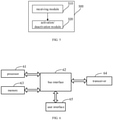
- a network device 200 including:
- the first field is used for at least one of the following:
- the multiple transmission configurations are transmission configurations associated with a first search space (SS) or a first control resource set (CORESET) in configuration information of the activation/deactivation information;
- the first SS is an SS where the activation/deactivation information is detected, and the first CORESET is a CORESET where the activation/deactivation information is detected.
- the activation information used for indicating activation of the multiple transmission configurations includes a second field, and the second field is used for indicating activation of second configuration information that is different among the multiple transmission configurations.
- the second configuration information includes at least one of the following:
- the second field is used for at least one of the following:
- the first field or the second field or a verification field in the activation/deactivation information is at least one of following items in downlink control information DCI:
- the network device embodiment of the present disclosure corresponds to the embodiment of the foregoing method, and all the implementations in the foregoing method embodiments are applicable to the network device embodiment, and the same technical effect can also be achieved.
- activation/deactivation information for indicating activation/deactivation of multiple transmission configurations is transmitted to a terminal; wherein the multiple transmission configurations are associated with the configuration information of the activation/deactivation information, or a first field of the activation/deactivation information is used for indicating activation/deactivation of first configuration information that is same among the multiple transmission configurations, thus multiple transmission configurations can be activated by a single piece of activation/deactivation information, and the problem of large overhead and high latency when multiple transmission configurations are activated is solved.
- the present disclosure further provides a network device
- the network device includes: a processor 300; a memory 320 connected to the processor 300 through a bus interface, and a transceiver 310 connected to the processor 300 through the bus interface; the memory 320 is used to store programs and data used by the processor when performing operations; the transceiver 310 is used to transmit data information or pilots, and also used to receive uplink control channel; when the processor 300 calls and executes the programs and data stored in the memory 320, the following functions are realized.
- the processor 300 is configured to read the program in the memory 320 and execute the following process:
- the multiple transmission configurations are transmission configurations associated with a first search space (SS) or a first control resource set (CORESET) in configuration information of the activation/deactivation information;
- the first SS is an SS where the activation/deactivation information is detected, and the first CORESET is a CORESET where the activation/deactivation information is detected.
- the activation information used for indicating activation of the multiple transmission configurations includes a second field, and the second field is used for indicating activation of second configuration information that is different among the multiple transmission configurations.
- the second configuration information includes at least one of the following:
- the first field or the second field or a verification field in the activation/deactivation information is at least one of following items in downlink control information (DCI):
- the transceiver 310 is configured to receive and transmit data under the control of the processor 300.
- the bus architecture may include any number of interconnected buses and bridges, specifically various circuits such as one or more processors represented by the processor 300 and the memory represented by the memory 320 are connected together.
- the bus architecture can also connect various other circuits such as peripheral devices, voltage regulators, power management circuits, etc., which are all known in the field, and therefore, will not be further described herein.
- the bus interface provides the interface.
- the transceiver 310 may be a plurality of elements, that is, including a transmitter and a receiver, and provide a unit for communicating with various other devices on the transmission medium.
- the processor 300 is responsible for managing the bus architecture and general processing, and the memory 320 can store data used by the processor 300 when performing operations.
- the computer program includes instructions for performing parts or all of the steps of the above-mentioned method; and the computer program can be stored in a readable storage medium, and the storage medium can be any form of storage medium.
- Some embodiments of the present disclosure further provide a computer-readable storage medium storing thereon a computer program.
- a computer program When the computer program is executed by a processor, each process of the above-mentioned information transmission method embodiment is realized, and the same technical effect can be achieved. In order to avoid repetition, a detailed description thereof is omitted.
- the computer-readable storage medium is, for example, a read-only memory (ROM), random access memory (RAM), magnetic disk, or optical disc, etc.
- the configuration activation/deactivation method in some embodiments of the present disclosure is described above from the perspective of a network device side.
- a configuration activation/deactivation method on a terminal side will be further described below with reference to the drawing.
- some embodiments of the present disclosure provide a configuration activation/deactivation method.
- the method includes a step 41 and a step 42.
- Step 41 receiving activation/deactivation information for indicating activation/deactivation of multiple transmission configurations that is transmitted by a network device.
- the multiple transmission configurations are associated with configuration information of the activation/deactivation information, or a first field of the activation/deactivation information is used for indicating activation/deactivation of first configuration information that is same among the multiple transmission configurations.
- Step 42 activating/deactivating the multiple transmission configurations according to the activation/deactivation information.
- the transmission configuration is used for uplink data transmission or downlink data transmission.
- the activation/deactivation information can be uplink control information or downlink control information, that is, the configuration activation/deactivation method in some embodiments of the present disclosure can be applied to activation/deactivation of the transmission configuration of uplink data transmission, and it can also be applied to activation/deactivation of the transmission configuration of downlink data transmission.
- activation/deactivation information for indicating activation/deactivation of multiple transmission configurations that is transmitted by a network device is received; wherein the multiple transmission configurations are associated with the configuration information of the activation/deactivation information, or a first field of the activation/deactivation information is used for indicating activation/deactivation of first configuration information that is same among the multiple transmission configurations, thus multiple transmission configurations can be activated by a single piece of activation/deactivation information, and the problem of large overhead and high latency when multiple transmission configurations are activated is solved.
- a first field is used for indicating activation of the first configuration information that is same among the multiple transmission configurations.
- the first field may be a newly added field in DCI, or it may be one of the following items in DCI:
- activation/deactivation information for indicating activation/deactivation of multiple transmission configurations is transmitted to a terminal; the multiple transmission configurations are associated with configuration information of the activation/deactivation information.
- the multiple transmission configurations are transmission configurations associated with a first search space (SS) or a first control resource set (CORESET) in configuration information of the activation/deactivation information;
- the first SS is an SS where the activation/deactivation information is detected, and the first CORESET is a CORESET where the activation/deactivation information is detected.
- the activation/deactivation information may be DCI, and configuration information of DCI includes SS, CORESET or the like in DCI.
- the transmission configuration to be activated/deactivated can be determined according to the correspondence relationship between SSs or CORESETs and configuration indexes.
- the correspondence relationship between SSs or CORESETs and configuration indexes may be configured through RRC, and one SS or CORESET may correspond to one or more configuration indexes.
- the activation information used for indicating activation of the multiple transmission configurations includes a second field, and the second field is used for indicating activation of second configuration information that is different among the multiple transmission configurations.
- the second configuration information includes at least one of the following:
- the first field may be a newly added field in DCI or one of the following items in DCI:
- the following describes, in combination with uplink transmission, the configuration activation/deactivation method on a network device side and a terminal side.
- Step 1 after a network device (gNB) establishes a connection with a terminal, the network device performs semi-static configuration of the type 2 uplink grant-free transmission for the terminal, the configuration information includes: resource configuration period, etc.
- gNB network device
- Step 2 the network device generates the first part of the activation information, namely, the first field and the second field; for example, frequency domain resource allocation, time domain resource allocation, MCS, etc., also including activation index, and/or, DMRS pattern, and /or, time domain offset pattern.
- the network device generates the first part of the activation information, namely, the first field and the second field; for example, frequency domain resource allocation, time domain resource allocation, MCS, etc., also including activation index, and/or, DMRS pattern, and /or, time domain offset pattern.
- Step 3 the network device generates the second part of the activation information, namely, verification field.
- Step 4 the network device uses CS-RNTI to scramble PDCCH and at the same time sets NDI field to 0.
- Step 5 the network device transmits the generated PDCCH to activate the type 2 uplink grant-free transmission.
- Step 6 the terminal receives the PDCCH, and descrambles the CRC check bit by using the CS-RNTI to check whether the NDI field is set to 0; after the above conditions are met, the terminal will further verify the verification field of the PDCCH according to the activation information.
- Step 7 after verifying the activation information, the terminal obtains the signalling of the type 2 uplink grant-free transmission.
- Step 8 after the configuration is activated, the network device and terminal can periodically use the configured time-frequency resources to perform data transmission.
- the terminal will periodically transmit data on the designated semi-statically scheduled resources, and the network equipment will periodically receive data on the designated semi-statically scheduled resources.
- Step 9 after the type 2 grant-free uplink transmission is completed, the network device transmits deactivation information (release signalling), and after the terminal correctly detects and obtains the release signalling, the type 2 grant-free uplink transmission ends.
- deactivation information release signalling
- a terminal 500 including:
- the first field is used for at least one of the following:
- the multiple transmission configurations are transmission configurations associated with a first search space (SS) or a first control resource set (CORESET) in configuration information of the activation/deactivation information;
- the first SS is an SS where the activation/deactivation information is detected, and the first CORESET is a CORESET where the activation/deactivation information is detected.
- the activation information used for indicating activation of the multiple transmission configurations includes a second field, and the second field is used for indicating activation of second configuration information that is different among the multiple transmission configurations.
- the second configuration information includes at least one of the following:
- the second field is used for at least one of the following:
- the first field or the second field or a verification field in the activation/deactivation information is at least one of following items in downlink control information DCI:
- the terminal embodiment of the present disclosure corresponds to the embodiment of the above method, and all the implementations in the above method embodiment are applicable to the embodiment of the terminal, and the same technical effect can also be achieved.
- activation/deactivation information for indicating activation/deactivation of multiple transmission configurations that is transmitted by a network device is received; wherein the multiple transmission configurations are associated with the configuration information of the activation/deactivation information, or a first field of the activation/deactivation information is used for indicating activation/deactivation of first configuration information that is same among the multiple transmission configurations, thus multiple transmission configurations can be activated by a single piece of activation/deactivation information, and the problem of large overhead and high latency when multiple transmission configurations are activated is solved.
- this embodiment provides a terminal, including: a processor 61; and a memory 63 connected to the processor 61 through a bus interface 62, and the memory 63 is used for storing programs and data used by the processor 61 when performing operations, when the processor 61 calls and executes the programs and data stored in the memory 63, following process is executed.
- the transceiver 64 is connected to the bus interface 62 for receiving and transmitting data under the control of the processor 61.
- the processor 61 executes the program to implements the following steps: receiving activation/deactivation information for indicating activation/deactivation of multiple transmission configurations that is transmitted by a network device; wherein, the multiple transmission configurations are associated with configuration information of the activation/deactivation information, or a first field of the activation/deactivation information is used for indicating activation/deactivation of first configuration information that is same among the multiple transmission configurations; and activating/deactivating the multiple transmission configurations according to the activation/deactivation information.
- the multiple transmission configurations are transmission configurations associated with a first search space (SS) or a first control resource set (CORESET) in configuration information of the activation/deactivation information;
- the first SS is an SS where the activation/deactivation information is detected, and the first CORESET is a CORESET where the activation/deactivation information is detected.
- the activation information used for indicating activation of the multiple transmission configurations includes a second field, and the second field is used for indicating activation of second configuration information that is different among the multiple transmission configurations.
- the second configuration information includes at least one of the following:
- the first field or the second field or a verification field in the activation/deactivation information is at least one of following items in downlink control information (DCI):
- the bus architecture may include any number of interconnected buses and bridges, specifically various circuits such as one or more processors represented by the processor 61 and the memory represented by the memory 63 are connected together.
- the bus architecture can also connect various other circuits such as peripheral devices, voltage regulators, power management circuits, etc., which are all known in the field, and therefore, will not be further described herein.
- the bus interface provides the interface.
- the transceiver 64 may be a plurality of elements, that is, including a transmitter and a receiver, and provide a unit for communicating with various other devices on the transmission medium.
- the user interface 65 may also be an interface capable of connecting externally or internally to required equipment.
- the connected equipment includes, but is not limited to, a keypad, a display, a speaker, a microphone, a joystick, etc.
- the processor 61 is responsible for managing the bus architecture and general processing, and the memory 63 can store data used by the processor 61 when performing operations.
- the computer program includes instructions for performing parts or all of the steps of the above-mentioned method; and the computer program can be stored in a readable storage medium, and the storage medium can be any form of storage medium.
- Some embodiments of the present disclosure further provide a computer-readable storage medium storing thereon a computer program.
- a computer program When the computer program is executed by a processor, various processes of the above-mentioned information transmission method embodiment are realized, and the same technical effect can be achieved. In order to avoid repetition, it won't be repeated here.
- the computer-readable storage medium is for example a read-only memory (ROM), random access memory (RAM), magnetic disk, optical disc, or the like.
- a module, unit, submodule, subunit and the like can be implemented in one or more application-specific integrated circuits (ASIC), digital signal processors (DSP), digital signal processing devices (DSP Device, DSPD), programmable logic devices (PLD), Field-Programmable Gate Arrays (FPGA), general-purpose processors, controllers, microcontrollers, microprocessors, other electronic units for performing the functions described in this disclosure or a combination thereof.
- ASIC application-specific integrated circuits
- DSP digital signal processors
- DSP Device digital signal processing devices
- PLD programmable logic devices
- FPGA Field-Programmable Gate Arrays
- general-purpose processors controllers, microcontrollers, microprocessors, other electronic units for performing the functions described in this disclosure or a combination thereof.
- the technology described in the embodiments of the present disclosure can be implemented by modules (for example, procedures, functions, etc.) that perform the functions described in the embodiments of the present disclosure.
- the software codes can be stored in the memory and executed by the processor.
- the memory can be implemented in the processor or external to the processor.
- the purpose of the present disclosure can also be realized by running a program or a group of programs on any computing device.
- the computing device may be a well-known general-purpose device. Therefore, the purpose of the present disclosure can also be achieved only by providing a program product containing program code for implementing the method or device of the present disclosure. That is, such a program product also constitutes the present disclosure, and a storage medium storing such a program product also constitutes the present disclosure. Obviously, the storage medium may be any well-known storage medium, or any storage medium developed in the future. It should also be pointed out that in the device and method of the present disclosure, obviously, each component or each step can be decomposed and/or recombined.
- each component or each step can be decomposed and/or recombined.
- This decomposition and/or recombination should be regarded as equivalent solutions of the present disclosure.
- the steps of the above-mentioned series of processing can be executed naturally in a chronological order of description, but it is not necessarily executed in the chronological order. Some steps can be performed in parallel or independently of each other.
- a person skilled in the art can understand that all or any of the steps or components of the method and device of the present disclosure can be used in any computing device (including a processor, storage medium, etc.) or a network of computing devices, and can be implemented by hardware, firmware, software, or any combination thereof. This can be achieved by a person skilled in the art using their basic programming skills after reading the description of the present disclosure.
- the purpose of the present disclosure can also be realized by running a program or a group of programs on any computing device.
- the computing device may be a well-known general-purpose device. Therefore, the purpose of the present disclosure can also be achieved only by providing a program product containing program code for implementing the method or device of the present disclosure. That is, such a program product also constitutes the present disclosure, and a storage medium storing such a program product also constitutes the present disclosure. Obviously, the storage medium may be any well-known storage medium, or any storage medium developed in the future. It should also be pointed out that in the device and method of the present disclosure, obviously, each component or each step can be decomposed and/or recombined.
Landscapes
- Engineering & Computer Science (AREA)
- Signal Processing (AREA)
- Computer Networks & Wireless Communication (AREA)
- Mobile Radio Communication Systems (AREA)
Applications Claiming Priority (2)
| Application Number | Priority Date | Filing Date | Title |
|---|---|---|---|
| CN201910365360.4A CN111867117B (zh) | 2019-04-30 | 2019-04-30 | 一种激活/去激活配置的方法、网络设备及终端 |
| PCT/CN2020/086092 WO2020221078A1 (zh) | 2019-04-30 | 2020-04-22 | 激活/去激活配置的方法、网络设备及终端 |
Publications (3)
| Publication Number | Publication Date |
|---|---|
| EP3965510A1 true EP3965510A1 (de) | 2022-03-09 |
| EP3965510A4 EP3965510A4 (de) | 2022-06-22 |
| EP3965510B1 EP3965510B1 (de) | 2024-01-10 |
Family
ID=72965740
Family Applications (1)
| Application Number | Title | Priority Date | Filing Date |
|---|---|---|---|
| EP20798472.5A Active EP3965510B1 (de) | 2019-04-30 | 2020-04-22 | Konfigurationsaktivierungs-/deaktivierungsverfahren, netzwerkgerät und endgerät |
Country Status (6)
| Country | Link |
|---|---|
| US (1) | US12047968B2 (de) |
| EP (1) | EP3965510B1 (de) |
| KR (1) | KR102730218B1 (de) |
| CN (1) | CN111867117B (de) |
| TW (1) | TWI751541B (de) |
| WO (1) | WO2020221078A1 (de) |
Families Citing this family (5)
| Publication number | Priority date | Publication date | Assignee | Title |
|---|---|---|---|---|
| CN116114355A (zh) * | 2021-01-15 | 2023-05-12 | Oppo广东移动通信有限公司 | 无线通信方法、终端设备和网络设备 |
| US11889496B2 (en) * | 2021-06-03 | 2024-01-30 | Qualcomm Incorporated | Activation of multiple configurations |
| US20240414072A1 (en) * | 2021-10-21 | 2024-12-12 | Apple Inc. | Session Continuity Support for New Radio Quality of Experience |
| WO2023155172A1 (zh) * | 2022-02-18 | 2023-08-24 | Oppo广东移动通信有限公司 | 通信方法和设备 |
| CN118749224A (zh) * | 2022-06-06 | 2024-10-08 | 联想(北京)有限公司 | 利用dci指示的ntn iot harq禁用 |
Family Cites Families (27)
| Publication number | Priority date | Publication date | Assignee | Title |
|---|---|---|---|---|
| CN102149208B (zh) * | 2010-02-05 | 2013-11-06 | 华为技术有限公司 | 载波激活相关信息的处理方法、基站及ue |
| EP2536047B1 (de) * | 2010-02-09 | 2020-03-04 | LG Electronics Inc. | Verfahren zur übertragung eines uplink-signals in einem drahtlosen kommunikationssystem und vorrichtung dafür |
| KR101708574B1 (ko) * | 2012-08-23 | 2017-02-20 | 인터디지탈 패튼 홀딩스, 인크 | 무선 시스템에서의 다중 스케줄러들을 이용한 동작 |
| JP6697095B2 (ja) * | 2016-05-10 | 2020-05-20 | オッポ広東移動通信有限公司Guangdong Oppo Mobile Telecommunications Corp., Ltd. | 通信方法と通信装置 |
| EP3455985B1 (de) | 2016-05-11 | 2022-03-09 | Convida Wireless, LLC | Neuer funk-downlink-steuerkanal |
| WO2017193406A1 (zh) | 2016-05-13 | 2017-11-16 | 华为技术有限公司 | 一种业务数据传输方法、用户设备及网络设备 |
| CN113692059B (zh) * | 2016-05-30 | 2023-12-15 | 北京三星通信技术研究有限公司 | 无线通信系统中的方法和设备 |
| EP3482595B1 (de) | 2016-07-07 | 2021-09-01 | LG Electronics Inc. | Verfahren und benutzergerät zum empfangen eines downlink-signals |
| KR102771072B1 (ko) * | 2016-08-11 | 2025-02-19 | 이노스카이 주식회사 | V2x를 위한 준영구적 스케줄링 방법 및 장치 |
| EP3509227A4 (de) * | 2016-09-22 | 2019-07-24 | Huawei Technologies Co., Ltd. | Messkonfigurationsverfahren und -vorrichtung |
| CA3038517A1 (en) * | 2016-09-28 | 2018-04-05 | Sharp Kabushiki Kaisha | User equipments, base stations and methods |
| US10959218B2 (en) * | 2016-11-14 | 2021-03-23 | Comcast Cable Communications, Llc | Semi-persistent scheduling confirmation |
| KR102164967B1 (ko) * | 2017-01-06 | 2020-10-13 | 한국전자통신연구원 | 통신 시스템에서 제어 채널의 송수신 방법 및 장치 |
| US10736083B2 (en) * | 2017-05-01 | 2020-08-04 | Huawei Technologies Co., Ltd. | Systems and methods for downlink control channel signaling for uplink transmission |
| CN108882371B (zh) * | 2017-05-15 | 2021-03-23 | 华为技术有限公司 | 一种资源配置方法、设备及系统 |
| CN109246680B (zh) * | 2017-06-15 | 2020-08-14 | 维沃移动通信有限公司 | 一种数据多发处理方法、终端及网络设备 |
| ES2760935T3 (es) * | 2017-08-18 | 2020-05-18 | Asustek Comp Inc | Procedimiento y aparato para la configuración de acceso aleatorio en un sistema de comunicación inalámbrica |
| CN109587795B (zh) * | 2017-09-29 | 2020-10-30 | 中国移动通信有限公司研究院 | 一种上行数据免授权传输方法、装置和介质 |
| CN111264084B (zh) * | 2017-10-10 | 2022-04-05 | 联想(北京)有限公司 | 确定传输方案 |
| JP7094090B2 (ja) * | 2017-10-20 | 2022-07-01 | シャープ株式会社 | 端末装置、基地局装置、および、通信方法 |
| US10567145B2 (en) * | 2018-01-05 | 2020-02-18 | Ofinno, Llc | Beam reports with multiple cells |
| CN110034874B (zh) * | 2018-01-11 | 2020-11-17 | 维沃移动通信有限公司 | 一种资源监听方法、终端及基站 |
| ES2960749T3 (es) * | 2018-01-19 | 2024-03-06 | Ntt Docomo Inc | Equipo de usuario en sistema de comunicación inalámbrico |
| KR102486812B1 (ko) * | 2018-04-12 | 2023-01-11 | 삼성전자주식회사 | 전자 장치 및 전자 장치에서 대역폭 적응 기반 전력 제어 방법 |
| BR112020021375B1 (pt) * | 2018-04-20 | 2023-01-24 | Telefonaktiebolaget Lm Ericsson (Publ) | Nó de rede, equipamento de usuário e métodos para ativar ou desativar recursos de sinal de referência utilizáveis para gerenciamento de feixes de transmissão e/ou recepção relacionados |
| US20220007411A1 (en) * | 2018-11-01 | 2022-01-06 | Ntt Docomo, Inc. | User terminal |
| CN112385252B (zh) * | 2018-11-01 | 2024-08-09 | 松下电器(美国)知识产权公司 | 发送设备、接收设备及其方法 |
-
2019
- 2019-04-30 CN CN201910365360.4A patent/CN111867117B/zh active Active
-
2020
- 2020-04-22 WO PCT/CN2020/086092 patent/WO2020221078A1/zh not_active Ceased
- 2020-04-22 US US17/607,836 patent/US12047968B2/en active Active
- 2020-04-22 EP EP20798472.5A patent/EP3965510B1/de active Active
- 2020-04-22 KR KR1020217038677A patent/KR102730218B1/ko active Active
- 2020-04-28 TW TW109114142A patent/TWI751541B/zh active
Also Published As
| Publication number | Publication date |
|---|---|
| KR20220005533A (ko) | 2022-01-13 |
| TW202042579A (zh) | 2020-11-16 |
| US20220232612A1 (en) | 2022-07-21 |
| WO2020221078A1 (zh) | 2020-11-05 |
| TWI751541B (zh) | 2022-01-01 |
| US12047968B2 (en) | 2024-07-23 |
| EP3965510A4 (de) | 2022-06-22 |
| CN111867117B (zh) | 2022-04-29 |
| KR102730218B1 (ko) | 2024-11-13 |
| EP3965510B1 (de) | 2024-01-10 |
| CN111867117A (zh) | 2020-10-30 |
Similar Documents
| Publication | Publication Date | Title |
|---|---|---|
| US12047968B2 (en) | Configuration activation/deactivation method, network device and terminal | |
| CN111082915B (zh) | 一种无线通信中的方法和装置 | |
| JP7230242B2 (ja) | Harq-ackの伝送方法、ユーザ機器及びネットワーク側機器 | |
| US12133234B2 (en) | Uplink channel transmission method, terminal, and base station | |
| CN109802771B (zh) | 数据传输方法、终端、基站及存储介质 | |
| CN111787630B (zh) | 一种业务传输方法、装置、终端及基站 | |
| US20220287074A1 (en) | Resource transmission method, terminal and network device | |
| US11497003B2 (en) | Information transmission method, terminal and network device | |
| CN111432476B (zh) | 一种波束方向的指示方法、基站及终端 | |
| US10779298B2 (en) | Uplink data sending method, uplink data scheduling method, and apparatus | |
| KR102535440B1 (ko) | Nr tdd 라디오 프레임 구성 및 cli 민감도의 gnb-간 xn 시그널링 | |
| CN110855406B (zh) | 相位跟踪参考信号ptrs传输方法、网络设备及终端 | |
| KR20240134207A (ko) | 무선 통신 네트워크에서 다수의 시간 도메인 리소스에 걸친 송신 | |
| CN110831218B (zh) | 一种信息传输方法、基站及终端 | |
| CN112350805B (zh) | 一种信息传输方法、终端及基站 | |
| EP3965350B1 (de) | Informationsübertragungsverfahren, netzwerkvorrichtung und endgerät | |
| CN110958083A (zh) | 通信方法及装置 |
Legal Events
| Date | Code | Title | Description |
|---|---|---|---|
| STAA | Information on the status of an ep patent application or granted ep patent |
Free format text: STATUS: THE INTERNATIONAL PUBLICATION HAS BEEN MADE |
|
| PUAI | Public reference made under article 153(3) epc to a published international application that has entered the european phase |
Free format text: ORIGINAL CODE: 0009012 |
|
| STAA | Information on the status of an ep patent application or granted ep patent |
Free format text: STATUS: REQUEST FOR EXAMINATION WAS MADE |
|
| 17P | Request for examination filed |
Effective date: 20211103 |
|
| AK | Designated contracting states |
Kind code of ref document: A1 Designated state(s): AL AT BE BG CH CY CZ DE DK EE ES FI FR GB GR HR HU IE IS IT LI LT LU LV MC MK MT NL NO PL PT RO RS SE SI SK SM TR |
|
| REG | Reference to a national code |
Ref country code: DE Ipc: H04W0072040000 Ref country code: DE Ref legal event code: R079 Ref document number: 602020024269 Country of ref document: DE Free format text: PREVIOUS MAIN CLASS: H04W0072120000 Ipc: H04W0072040000 |
|
| A4 | Supplementary search report drawn up and despatched |
Effective date: 20220525 |
|
| RIC1 | Information provided on ipc code assigned before grant |
Ipc: H04L 5/00 20060101ALI20220519BHEP Ipc: H04W 72/04 20090101AFI20220519BHEP |
|
| DAV | Request for validation of the european patent (deleted) | ||
| DAX | Request for extension of the european patent (deleted) | ||
| STAA | Information on the status of an ep patent application or granted ep patent |
Free format text: STATUS: EXAMINATION IS IN PROGRESS |
|
| 17Q | First examination report despatched |
Effective date: 20230127 |
|
| REG | Reference to a national code |
Ref country code: DE Ref legal event code: R079 Free format text: PREVIOUS MAIN CLASS: H04W0072040000 Ipc: H04W0072230000 Ref country code: DE Ref legal event code: R079 Ref document number: 602020024269 Country of ref document: DE Free format text: PREVIOUS MAIN CLASS: H04W0072040000 Ipc: H04W0072230000 |
|
| GRAP | Despatch of communication of intention to grant a patent |
Free format text: ORIGINAL CODE: EPIDOSNIGR1 |
|
| RIC1 | Information provided on ipc code assigned before grant |
Ipc: H04L 5/00 20060101ALI20230614BHEP Ipc: H04W 72/23 20230101AFI20230614BHEP |
|
| STAA | Information on the status of an ep patent application or granted ep patent |
Free format text: STATUS: GRANT OF PATENT IS INTENDED |
|
| INTG | Intention to grant announced |
Effective date: 20230720 |
|
| GRAS | Grant fee paid |
Free format text: ORIGINAL CODE: EPIDOSNIGR3 |
|
| GRAA | (expected) grant |
Free format text: ORIGINAL CODE: 0009210 |
|
| STAA | Information on the status of an ep patent application or granted ep patent |
Free format text: STATUS: THE PATENT HAS BEEN GRANTED |
|
| AK | Designated contracting states |
Kind code of ref document: B1 Designated state(s): AL AT BE BG CH CY CZ DE DK EE ES FI FR GB GR HR HU IE IS IT LI LT LU LV MC MK MT NL NO PL PT RO RS SE SI SK SM TR |
|
| REG | Reference to a national code |
Ref country code: GB Ref legal event code: FG4D |
|
| REG | Reference to a national code |
Ref country code: CH Ref legal event code: EP |
|
| REG | Reference to a national code |
Ref country code: DE Ref legal event code: R096 Ref document number: 602020024269 Country of ref document: DE |
|
| REG | Reference to a national code |
Ref country code: IE Ref legal event code: FG4D |
|
| REG | Reference to a national code |
Ref country code: LT Ref legal event code: MG9D |
|
| REG | Reference to a national code |
Ref country code: NL Ref legal event code: MP Effective date: 20240110 |
|
| REG | Reference to a national code |
Ref country code: AT Ref legal event code: MK05 Ref document number: 1649861 Country of ref document: AT Kind code of ref document: T Effective date: 20240110 |
|
| PG25 | Lapsed in a contracting state [announced via postgrant information from national office to epo] |
Ref country code: NL Free format text: LAPSE BECAUSE OF FAILURE TO SUBMIT A TRANSLATION OF THE DESCRIPTION OR TO PAY THE FEE WITHIN THE PRESCRIBED TIME-LIMIT Effective date: 20240110 |
|
| PG25 | Lapsed in a contracting state [announced via postgrant information from national office to epo] |
Ref country code: NL Free format text: LAPSE BECAUSE OF FAILURE TO SUBMIT A TRANSLATION OF THE DESCRIPTION OR TO PAY THE FEE WITHIN THE PRESCRIBED TIME-LIMIT Effective date: 20240110 |
|
| PG25 | Lapsed in a contracting state [announced via postgrant information from national office to epo] |
Ref country code: IS Free format text: LAPSE BECAUSE OF FAILURE TO SUBMIT A TRANSLATION OF THE DESCRIPTION OR TO PAY THE FEE WITHIN THE PRESCRIBED TIME-LIMIT Effective date: 20240510 |
|
| PG25 | Lapsed in a contracting state [announced via postgrant information from national office to epo] |
Ref country code: LT Free format text: LAPSE BECAUSE OF FAILURE TO SUBMIT A TRANSLATION OF THE DESCRIPTION OR TO PAY THE FEE WITHIN THE PRESCRIBED TIME-LIMIT Effective date: 20240110 |
|
| PG25 | Lapsed in a contracting state [announced via postgrant information from national office to epo] |
Ref country code: GR Free format text: LAPSE BECAUSE OF FAILURE TO SUBMIT A TRANSLATION OF THE DESCRIPTION OR TO PAY THE FEE WITHIN THE PRESCRIBED TIME-LIMIT Effective date: 20240411 |
|
| PG25 | Lapsed in a contracting state [announced via postgrant information from national office to epo] |
Ref country code: RS Free format text: LAPSE BECAUSE OF FAILURE TO SUBMIT A TRANSLATION OF THE DESCRIPTION OR TO PAY THE FEE WITHIN THE PRESCRIBED TIME-LIMIT Effective date: 20240410 Ref country code: HR Free format text: LAPSE BECAUSE OF FAILURE TO SUBMIT A TRANSLATION OF THE DESCRIPTION OR TO PAY THE FEE WITHIN THE PRESCRIBED TIME-LIMIT Effective date: 20240110 |
|
| PG25 | Lapsed in a contracting state [announced via postgrant information from national office to epo] |
Ref country code: ES Free format text: LAPSE BECAUSE OF FAILURE TO SUBMIT A TRANSLATION OF THE DESCRIPTION OR TO PAY THE FEE WITHIN THE PRESCRIBED TIME-LIMIT Effective date: 20240110 |
|
| PG25 | Lapsed in a contracting state [announced via postgrant information from national office to epo] |
Ref country code: AT Free format text: LAPSE BECAUSE OF FAILURE TO SUBMIT A TRANSLATION OF THE DESCRIPTION OR TO PAY THE FEE WITHIN THE PRESCRIBED TIME-LIMIT Effective date: 20240110 |
|
| PG25 | Lapsed in a contracting state [announced via postgrant information from national office to epo] |
Ref country code: RS Free format text: LAPSE BECAUSE OF FAILURE TO SUBMIT A TRANSLATION OF THE DESCRIPTION OR TO PAY THE FEE WITHIN THE PRESCRIBED TIME-LIMIT Effective date: 20240410 Ref country code: NO Free format text: LAPSE BECAUSE OF FAILURE TO SUBMIT A TRANSLATION OF THE DESCRIPTION OR TO PAY THE FEE WITHIN THE PRESCRIBED TIME-LIMIT Effective date: 20240410 Ref country code: LT Free format text: LAPSE BECAUSE OF FAILURE TO SUBMIT A TRANSLATION OF THE DESCRIPTION OR TO PAY THE FEE WITHIN THE PRESCRIBED TIME-LIMIT Effective date: 20240110 Ref country code: IS Free format text: LAPSE BECAUSE OF FAILURE TO SUBMIT A TRANSLATION OF THE DESCRIPTION OR TO PAY THE FEE WITHIN THE PRESCRIBED TIME-LIMIT Effective date: 20240510 Ref country code: HR Free format text: LAPSE BECAUSE OF FAILURE TO SUBMIT A TRANSLATION OF THE DESCRIPTION OR TO PAY THE FEE WITHIN THE PRESCRIBED TIME-LIMIT Effective date: 20240110 Ref country code: GR Free format text: LAPSE BECAUSE OF FAILURE TO SUBMIT A TRANSLATION OF THE DESCRIPTION OR TO PAY THE FEE WITHIN THE PRESCRIBED TIME-LIMIT Effective date: 20240411 Ref country code: ES Free format text: LAPSE BECAUSE OF FAILURE TO SUBMIT A TRANSLATION OF THE DESCRIPTION OR TO PAY THE FEE WITHIN THE PRESCRIBED TIME-LIMIT Effective date: 20240110 Ref country code: BG Free format text: LAPSE BECAUSE OF FAILURE TO SUBMIT A TRANSLATION OF THE DESCRIPTION OR TO PAY THE FEE WITHIN THE PRESCRIBED TIME-LIMIT Effective date: 20240110 Ref country code: AT Free format text: LAPSE BECAUSE OF FAILURE TO SUBMIT A TRANSLATION OF THE DESCRIPTION OR TO PAY THE FEE WITHIN THE PRESCRIBED TIME-LIMIT Effective date: 20240110 |
|
| PG25 | Lapsed in a contracting state [announced via postgrant information from national office to epo] |
Ref country code: PL Free format text: LAPSE BECAUSE OF FAILURE TO SUBMIT A TRANSLATION OF THE DESCRIPTION OR TO PAY THE FEE WITHIN THE PRESCRIBED TIME-LIMIT Effective date: 20240110 Ref country code: PT Free format text: LAPSE BECAUSE OF FAILURE TO SUBMIT A TRANSLATION OF THE DESCRIPTION OR TO PAY THE FEE WITHIN THE PRESCRIBED TIME-LIMIT Effective date: 20240510 |
|
| PG25 | Lapsed in a contracting state [announced via postgrant information from national office to epo] |
Ref country code: SE Free format text: LAPSE BECAUSE OF FAILURE TO SUBMIT A TRANSLATION OF THE DESCRIPTION OR TO PAY THE FEE WITHIN THE PRESCRIBED TIME-LIMIT Effective date: 20240110 Ref country code: PT Free format text: LAPSE BECAUSE OF FAILURE TO SUBMIT A TRANSLATION OF THE DESCRIPTION OR TO PAY THE FEE WITHIN THE PRESCRIBED TIME-LIMIT Effective date: 20240510 Ref country code: PL Free format text: LAPSE BECAUSE OF FAILURE TO SUBMIT A TRANSLATION OF THE DESCRIPTION OR TO PAY THE FEE WITHIN THE PRESCRIBED TIME-LIMIT Effective date: 20240110 Ref country code: LV Free format text: LAPSE BECAUSE OF FAILURE TO SUBMIT A TRANSLATION OF THE DESCRIPTION OR TO PAY THE FEE WITHIN THE PRESCRIBED TIME-LIMIT Effective date: 20240110 |
|
| PG25 | Lapsed in a contracting state [announced via postgrant information from national office to epo] |
Ref country code: DK Free format text: LAPSE BECAUSE OF FAILURE TO SUBMIT A TRANSLATION OF THE DESCRIPTION OR TO PAY THE FEE WITHIN THE PRESCRIBED TIME-LIMIT Effective date: 20240110 |
|
| REG | Reference to a national code |
Ref country code: DE Ref legal event code: R097 Ref document number: 602020024269 Country of ref document: DE |
|
| PG25 | Lapsed in a contracting state [announced via postgrant information from national office to epo] |
Ref country code: SM Free format text: LAPSE BECAUSE OF FAILURE TO SUBMIT A TRANSLATION OF THE DESCRIPTION OR TO PAY THE FEE WITHIN THE PRESCRIBED TIME-LIMIT Effective date: 20240110 |
|
| PG25 | Lapsed in a contracting state [announced via postgrant information from national office to epo] |
Ref country code: EE Free format text: LAPSE BECAUSE OF FAILURE TO SUBMIT A TRANSLATION OF THE DESCRIPTION OR TO PAY THE FEE WITHIN THE PRESCRIBED TIME-LIMIT Effective date: 20240110 Ref country code: CZ Free format text: LAPSE BECAUSE OF FAILURE TO SUBMIT A TRANSLATION OF THE DESCRIPTION OR TO PAY THE FEE WITHIN THE PRESCRIBED TIME-LIMIT Effective date: 20240110 |
|
| PG25 | Lapsed in a contracting state [announced via postgrant information from national office to epo] |
Ref country code: SK Free format text: LAPSE BECAUSE OF FAILURE TO SUBMIT A TRANSLATION OF THE DESCRIPTION OR TO PAY THE FEE WITHIN THE PRESCRIBED TIME-LIMIT Effective date: 20240110 |
|
| PG25 | Lapsed in a contracting state [announced via postgrant information from national office to epo] |
Ref country code: SM Free format text: LAPSE BECAUSE OF FAILURE TO SUBMIT A TRANSLATION OF THE DESCRIPTION OR TO PAY THE FEE WITHIN THE PRESCRIBED TIME-LIMIT Effective date: 20240110 Ref country code: SK Free format text: LAPSE BECAUSE OF FAILURE TO SUBMIT A TRANSLATION OF THE DESCRIPTION OR TO PAY THE FEE WITHIN THE PRESCRIBED TIME-LIMIT Effective date: 20240110 Ref country code: RO Free format text: LAPSE BECAUSE OF FAILURE TO SUBMIT A TRANSLATION OF THE DESCRIPTION OR TO PAY THE FEE WITHIN THE PRESCRIBED TIME-LIMIT Effective date: 20240110 Ref country code: EE Free format text: LAPSE BECAUSE OF FAILURE TO SUBMIT A TRANSLATION OF THE DESCRIPTION OR TO PAY THE FEE WITHIN THE PRESCRIBED TIME-LIMIT Effective date: 20240110 Ref country code: DK Free format text: LAPSE BECAUSE OF FAILURE TO SUBMIT A TRANSLATION OF THE DESCRIPTION OR TO PAY THE FEE WITHIN THE PRESCRIBED TIME-LIMIT Effective date: 20240110 Ref country code: CZ Free format text: LAPSE BECAUSE OF FAILURE TO SUBMIT A TRANSLATION OF THE DESCRIPTION OR TO PAY THE FEE WITHIN THE PRESCRIBED TIME-LIMIT Effective date: 20240110 |
|
| PLBE | No opposition filed within time limit |
Free format text: ORIGINAL CODE: 0009261 |
|
| STAA | Information on the status of an ep patent application or granted ep patent |
Free format text: STATUS: NO OPPOSITION FILED WITHIN TIME LIMIT |
|
| PG25 | Lapsed in a contracting state [announced via postgrant information from national office to epo] |
Ref country code: MC Free format text: LAPSE BECAUSE OF FAILURE TO SUBMIT A TRANSLATION OF THE DESCRIPTION OR TO PAY THE FEE WITHIN THE PRESCRIBED TIME-LIMIT Effective date: 20240110 |
|
| PG25 | Lapsed in a contracting state [announced via postgrant information from national office to epo] |
Ref country code: MC Free format text: LAPSE BECAUSE OF FAILURE TO SUBMIT A TRANSLATION OF THE DESCRIPTION OR TO PAY THE FEE WITHIN THE PRESCRIBED TIME-LIMIT Effective date: 20240110 |
|
| REG | Reference to a national code |
Ref country code: CH Ref legal event code: PL |
|
| PG25 | Lapsed in a contracting state [announced via postgrant information from national office to epo] |
Ref country code: IT Free format text: LAPSE BECAUSE OF FAILURE TO SUBMIT A TRANSLATION OF THE DESCRIPTION OR TO PAY THE FEE WITHIN THE PRESCRIBED TIME-LIMIT Effective date: 20240110 |
|
| PG25 | Lapsed in a contracting state [announced via postgrant information from national office to epo] |
Ref country code: LU Free format text: LAPSE BECAUSE OF NON-PAYMENT OF DUE FEES Effective date: 20240422 |
|
| 26N | No opposition filed |
Effective date: 20241011 |
|
| REG | Reference to a national code |
Ref country code: BE Ref legal event code: MM Effective date: 20240430 |
|
| PG25 | Lapsed in a contracting state [announced via postgrant information from national office to epo] |
Ref country code: LU Free format text: LAPSE BECAUSE OF NON-PAYMENT OF DUE FEES Effective date: 20240422 Ref country code: IT Free format text: LAPSE BECAUSE OF FAILURE TO SUBMIT A TRANSLATION OF THE DESCRIPTION OR TO PAY THE FEE WITHIN THE PRESCRIBED TIME-LIMIT Effective date: 20240110 |
|
| PG25 | Lapsed in a contracting state [announced via postgrant information from national office to epo] |
Ref country code: BE Free format text: LAPSE BECAUSE OF NON-PAYMENT OF DUE FEES Effective date: 20240430 |
|
| PG25 | Lapsed in a contracting state [announced via postgrant information from national office to epo] |
Ref country code: BE Free format text: LAPSE BECAUSE OF NON-PAYMENT OF DUE FEES Effective date: 20240430 Ref country code: CH Free format text: LAPSE BECAUSE OF NON-PAYMENT OF DUE FEES Effective date: 20240430 |
|
| PG25 | Lapsed in a contracting state [announced via postgrant information from national office to epo] |
Ref country code: IE Free format text: LAPSE BECAUSE OF NON-PAYMENT OF DUE FEES Effective date: 20240422 |
|
| PG25 | Lapsed in a contracting state [announced via postgrant information from national office to epo] |
Ref country code: SI Free format text: LAPSE BECAUSE OF FAILURE TO SUBMIT A TRANSLATION OF THE DESCRIPTION OR TO PAY THE FEE WITHIN THE PRESCRIBED TIME-LIMIT Effective date: 20240110 |
|
| PGFP | Annual fee paid to national office [announced via postgrant information from national office to epo] |
Ref country code: DE Payment date: 20250422 Year of fee payment: 6 |
|
| PGFP | Annual fee paid to national office [announced via postgrant information from national office to epo] |
Ref country code: GB Payment date: 20250423 Year of fee payment: 6 |
|
| PGFP | Annual fee paid to national office [announced via postgrant information from national office to epo] |
Ref country code: FR Payment date: 20250425 Year of fee payment: 6 |
|
| PG25 | Lapsed in a contracting state [announced via postgrant information from national office to epo] |
Ref country code: CY Free format text: LAPSE BECAUSE OF FAILURE TO SUBMIT A TRANSLATION OF THE DESCRIPTION OR TO PAY THE FEE WITHIN THE PRESCRIBED TIME-LIMIT; INVALID AB INITIO Effective date: 20200422 |
|
| PG25 | Lapsed in a contracting state [announced via postgrant information from national office to epo] |
Ref country code: HU Free format text: LAPSE BECAUSE OF FAILURE TO SUBMIT A TRANSLATION OF THE DESCRIPTION OR TO PAY THE FEE WITHIN THE PRESCRIBED TIME-LIMIT; INVALID AB INITIO Effective date: 20200422 |
|
| PG25 | Lapsed in a contracting state [announced via postgrant information from national office to epo] |
Ref country code: FI Free format text: LAPSE BECAUSE OF FAILURE TO SUBMIT A TRANSLATION OF THE DESCRIPTION OR TO PAY THE FEE WITHIN THE PRESCRIBED TIME-LIMIT Effective date: 20240110 |