EP3965408B1 - Procédé et système de communication pour une opération d'économie d'énergie d'une ligne d'abonné - Google Patents
Procédé et système de communication pour une opération d'économie d'énergie d'une ligne d'abonné Download PDFInfo
- Publication number
- EP3965408B1 EP3965408B1 EP20194703.3A EP20194703A EP3965408B1 EP 3965408 B1 EP3965408 B1 EP 3965408B1 EP 20194703 A EP20194703 A EP 20194703A EP 3965408 B1 EP3965408 B1 EP 3965408B1
- Authority
- EP
- European Patent Office
- Prior art keywords
- network device
- interface
- port
- access
- customer router
- Prior art date
- Legal status (The legal status is an assumption and is not a legal conclusion. Google has not performed a legal analysis and makes no representation as to the accuracy of the status listed.)
- Active
Links
- 238000004891 communication Methods 0.000 title claims description 74
- 238000000034 method Methods 0.000 title claims description 23
- 230000003213 activating effect Effects 0.000 claims description 35
- 230000004044 response Effects 0.000 claims description 32
- 230000003287 optical effect Effects 0.000 claims description 29
- 230000011664 signaling Effects 0.000 claims description 24
- 230000005540 biological transmission Effects 0.000 claims description 13
- 239000013307 optical fiber Substances 0.000 claims description 12
- 230000033001 locomotion Effects 0.000 claims description 9
- 230000000977 initiatory effect Effects 0.000 claims description 7
- 230000006870 function Effects 0.000 description 5
- 230000008569 process Effects 0.000 description 5
- 238000010586 diagram Methods 0.000 description 3
- 238000005516 engineering process Methods 0.000 description 3
- 230000006399 behavior Effects 0.000 description 2
- 230000001413 cellular effect Effects 0.000 description 2
- 230000004913 activation Effects 0.000 description 1
- 239000003795 chemical substances by application Substances 0.000 description 1
- QVFWZNCVPCJQOP-UHFFFAOYSA-N chloralodol Chemical compound CC(O)(C)CC(C)OC(O)C(Cl)(Cl)Cl QVFWZNCVPCJQOP-UHFFFAOYSA-N 0.000 description 1
- 230000003247 decreasing effect Effects 0.000 description 1
- 230000001419 dependent effect Effects 0.000 description 1
- 230000000694 effects Effects 0.000 description 1
- 239000000835 fiber Substances 0.000 description 1
- 230000007420 reactivation Effects 0.000 description 1
- 230000009467 reduction Effects 0.000 description 1
- 238000001228 spectrum Methods 0.000 description 1
- 230000001960 triggered effect Effects 0.000 description 1
Images

Classifications
-
- H—ELECTRICITY
- H04—ELECTRIC COMMUNICATION TECHNIQUE
- H04M—TELEPHONIC COMMUNICATION
- H04M11/00—Telephonic communication systems specially adapted for combination with other electrical systems
- H04M11/06—Simultaneous speech and data transmission, e.g. telegraphic transmission over the same conductors
- H04M11/062—Simultaneous speech and data transmission, e.g. telegraphic transmission over the same conductors using different frequency bands for speech and other data
-
- H—ELECTRICITY
- H04—ELECTRIC COMMUNICATION TECHNIQUE
- H04L—TRANSMISSION OF DIGITAL INFORMATION, e.g. TELEGRAPHIC COMMUNICATION
- H04L12/00—Data switching networks
- H04L12/02—Details
- H04L12/12—Arrangements for remote connection or disconnection of substations or of equipment thereof
-
- Y—GENERAL TAGGING OF NEW TECHNOLOGICAL DEVELOPMENTS; GENERAL TAGGING OF CROSS-SECTIONAL TECHNOLOGIES SPANNING OVER SEVERAL SECTIONS OF THE IPC; TECHNICAL SUBJECTS COVERED BY FORMER USPC CROSS-REFERENCE ART COLLECTIONS [XRACs] AND DIGESTS
- Y02—TECHNOLOGIES OR APPLICATIONS FOR MITIGATION OR ADAPTATION AGAINST CLIMATE CHANGE
- Y02D—CLIMATE CHANGE MITIGATION TECHNOLOGIES IN INFORMATION AND COMMUNICATION TECHNOLOGIES [ICT], I.E. INFORMATION AND COMMUNICATION TECHNOLOGIES AIMING AT THE REDUCTION OF THEIR OWN ENERGY USE
- Y02D30/00—Reducing energy consumption in communication networks
- Y02D30/70—Reducing energy consumption in communication networks in wireless communication networks
Definitions
- the present invention is directed to a method for a power-saving operation of a subscriber line and a communication system for enabling a power-saving operation of a subscriber line, wherein the subscriber line may be an xDSL subscriber line or an optical fiber.
- Digital Subscriber Line (DSL) technology is deployed to provide digital broadband access to the Internet for example using a local telephone line.
- DSM energy-efficient dynamic spectrum management
- the method and the communication system allows a user to initiate a VoIP session to a called party or receive a VoIP call from a calling party even if the user's subscriber line is currently deactivated.
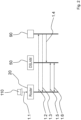
- communication system 10 which is configured to enable a power-saving operation of at least one subscriber line, wherein the at least subscriber line may be an xDSL subscriber line or an optical fiber.
- the communication system 10 comprises a wide-area wireless network 40, which is implemented as a low-power wide-area radio (LPWAN) network.
- the exemplary LPWAN network 40 is a type of a wireless telecommunication wide area network designed to allow long-range communications at a low bit rate and at low power.
- the illustrative LPWAN network 40 supports low-power wide-area network protocols such as LoRaWAN (LoRaWAN: Long Range Wide Area Network) developed by Semtech (see URL: https://en.wikipedia.org/wiki/LoRa).
- the LPWAN network may be based on the Narrowband Internet of Things (NB-IoT) which is a low-power wide area network radio technology standard developed by 3GPP (Third Generation Partnership Project).
- NB-IoT Narrowband Internet of Things
- the communication system 10 comprises a network device 90, which may constitute a physical server of an Internet service provider, that may operate an own ISP network 80.
- the network device 90 includes a communication interface 91 and a wireless network interface 93 configured to communicate via the wide-area wireless network 40.
- the wireless network interface 93 is implemented as a low-power radio network interface using a low-power wide-area network protocol, e.g. the LoRaWAN network protocol. In the following, thus interface 93 may be called a LPWAN interface.
- the network device 90 may include a control unit 92, which may be implemented as a microcontroller configured to control and monitor the functions of the network device 90.
- the communication system 10 comprises at least one customer router 20, which may be implemented as an Integrated Access Device (IAD), which may include a conventional xDSL modem.
- the customer router 20 may comprise at least a first xDSL access interface 23.1 and the customer router 20 comprises a wireless network interface 25, which may be implemented each as a physical and/or software component.
- Interface 25 is configured to communicate via the wide-area wireless network 40 with the network device 90.
- the wireless network interface 25 is a low-power radio network interface using a low-power wide-area network protocol, e.g. the LoRaWAN network protocol. In the following, thus interface 25 is called a LPWAN interface.
- the customer router 20 may comprise two access interfaces, namely xDSL access interface 23.1 and an xDSL access interface 23.2. It is to be noted, that alternatively the access interfaces 23.1 and 23.2 may be implemented as optical access interfaces. Furthermore, the customer router 20 may comprise a communication interface 21 configured to connect to a user end device 110.
- the user end device 110 may be a personal computer including, for example, a softphone and a Session Initiation Protocol (SIP) user agent client/server configured to establish and receive for example VoIP sessions.
- SIP Session Initiation Protocol
- the personal computer 110 may be connected via a cable to communication interface 21 of the customer router 20.
- Communication interface 21 may be implemented according to an Ethernet standard.
- the customer router 20 may comprise a Wi-Fi interface (not shown) which may be configured to communicate with a user end device via a wireless connection.
- the customer router 20 may include a control unit 26 configured to preferably control and monitor the functions of the customer router 20.
- a memory 27 may be implemented at the router 20 for storing e.g. data and/or instructions and/or application programs.
- at least one senor, e.g. a motion sensor 28 may be implemented at the customer router 20 for detecting a movement of the user.
- the system 10 comprises at least one access network device 50, which may be implemented as a digital subscriber line access multiplexer (DSLAM) or an multi-service access node (MSAN).
- DSLAM digital subscriber line access multiplexer
- MSAN multi-service access node
- the access network device 50 constitutes a DSLAM.
- the DSLAM 50 may comprise at least one xDSL port 51.1 and a communication interface 55 configured to communicate with the communication interface 91 of the network device 90.
- the DSLAM 50 may comprise two xDSL ports, namely the xDSL port 51.1 and and xDSL port 51.2.
- the DSLAM 50 may comprise a control unit 56 which may be implemented as a microcontroller configured to control and monitor the functions of the DSLAM 40.
- the xDSL ports 51.1 and 51.2 as well as the interfaces illustrated herein may be implemented as physical and/or software components.
- the communication system 10 may further comprise at least one xDSL subscriber line 100.1, which is terminated by the xDSL access interface 23.1 of the customer router 20 and by the first xDSL port 51.1 of the DSLAM 50.
- a second xDSL subscriber line 100.2 may be implemented which is terminated by the xDSL access interface 23.2 of the customer router 20 and by the xDSL port 51.2 of the DSLAM 50.
- the exemplary DSLAM 50 is configured to deactivate the xDSL port 51.1 and, if implemented, the xDSL port 51.2 in response to a time scheduler and/or in response to a predefined event.
- a respective time scheduler may be is stored in a memory 57 of the DSLAM 50.
- the DSLAM 50 and in particular the microcontroller 56 may be configured to detect a predefined event, which causes the access network device 50 to deactivate the xDSL port 50.1 and/or, if available, the xDSL port 51.2.
- a predefined event may be a user-based behavior such as the termination of an Internet session or a VoIP session, which may be detected by the access network device 50.
- the customer router 20 may be configured to trigger activation or reactivation of a deactivated xDSL subscriber line, e.g. the xDSL subscriber line 100.1 and/or, if implemented xDSL subscriber line 100.2., if needed by the user. This is done for example by transmitting a request message for activating xDSL port 51.1 of the access network device 50 via wireless network interface 25 to the network device 90.
- the control unit 26 is configured to cause the customer router 20 to transmit such a request message.
- the network device 90 may be configured to generate an xDSL port activating signal in response to the request message received from the customer router 20 and to transmit the xDSL port activating signal via its communication interface 91 to the access network device 50.
- the communication interfaces 55 and 91 can be connected via an electrical cable, an optical fiber or via a wireless connection.
- the control unit 56 of the access network device 50 may be configured to process and interpret the xDSL port activating signal to cause the DSLAM 50 to activate or reactivate the xDSL port 51.1 such that the xDSL subscriber line 100.1 will become available for data transmission between the customer device 20 and the access network devise 50.
- the request message transmitted by the customer router 20 may include information of the customer router 20 and/or the user and/or the xDSL interface 23.1 and/or the xDSL interface 23.2, which allows the network device 90 to generate a specific xDSL port activating signal which in turn carries information indicating to the access network device 50 which deactivated xDSL port or ports, e.g. xDSL port 51.1 and/or xDSL port 51.2 should be activated. It should be noted, that a plurality of xDSL ports 51.1 to 51.n may be implemented in the DSLAM 50 which may be associated with different customer routers.
- the preferred communication system 10 may include an IP-based communication subsystem 60, which may be implemented as the Internet Multimedia Subsystem (IMS).
- IMS Internet Multimedia Subsystem
- the Internet multimedia subsystem is described by Gerd Siegmund in the text book “Technik der Netze 2", 6. Auflage, Chapter 10, 2009, Wegig Verlag .
- the customer router 20 may be configured to transmit signaling messages, for example Session Initiation Protocol (SIP) messages generated by the personal computer 110, via its LPWAN interface 25 to the IP-based communication subsystem 60.
- the IP-based communication subsystem is preferably configured to provide multimedia services like Voice over IP (VoIP).
- a physical server 70 is associated with the IP-based communication subsystem 60.
- the server 70 may provide and support IP-based multimedia services like VoIP and may comprise a wireless network interface 73 configured to receive signaling messages from the customer router 20.
- the wireless network interface 73 may be implemented as a low-power radio network interface configured to support a low-wide-area network protocol such as the LoRaWAN network protocol.
- interface 73 may be called a LPWAN interface configured to communicate via the LPWAN network 40.
- the server 70 of the IP-based communication subsystem 60 may be further configured to transmit signaling messages, for example SIP messages received for example from a calling device 120, via its wireless network interface 73 to the customer router 20, which in turn is configured to receive the signaling messages from the IP-based communication subsystem 60 and the server 70, respectively.
- Signaling messages may be exchanged between the customer router 20 and the server 70 of the IP-based communication system 60 via the LPWAN network 40 as shown in Figure 1 .
- the process of transmitting signaling messages over the LPWAN network 40 to be exchanged between the customer router 20 and the IP-based communication subsystem 60 enables the user of the personal computer 110 to initiate a VoIP session or receive a VoIP call, even if the xDSL subscriber line 100.1 is deactivated or not available at all.
- the access network device 50 is also configured to deactivate the xDSL port 51.2 terminating the xDSL subscriber line 100.2. Furthermore, the customer router 20 is configured to transmit a request message for activating xDSL port 51.2 via its LPWAN interface 25 to the network device 90. The network device 90 in turn is configured to generate a port activating signal with respect to the second xDSL port 51.2 in response to the request message received from the customer router 20 and to transmit via its communication interface 91 the port activating signal with respect to the second xDSL port 51.2 to the access network device 50. Now the access network device may be configured to activate the xDSL port 50.2 and in a similar manner as described in detail with respect to the xDSL port 51.1.
- the at least one access interface 23.1 of customer router 20 may be implemented as an optical access interface which constitutes an optical network termination (ONT) of an optical fiber according to the Fiber to Home (FTTH) technology used to connect the customer device 20 to access network device 50.
- ONT optical network termination
- FTTH Fiber to Home
- the subscriber line 100.1 and, if implemented, the subscriber line 100.2 constitute each an optical fiber.
- the access network device 50 can be implemented as an MSAN device, which may comprise at least one optical port 51.1, which constitutes an optical line termination (OLT) and the communication interface 55 configured to communicate with the communication interface 91 of the network device 90.
- the MSLAN 50 may comprise two optical ports, namely optical port 51.1 and optical port 51.2.
- the MSLAN 50 may comprise the control unit 56, which may be implemented as a microcontroller configured to control and monitor the functions of the MSLAN 40.
- the optical ports 51.1 and 51.2 as well as the interfaces illustrated herein may be implemented as physical and/or software components. Therefore, the access network device 50 may be configured to deactivate the optical port 51.1 and, if available, the optical port 51.2.
- optical fiber 100.1 is terminated by the optical access interface 23.1 of the customer router 20 and by the first optical port 51.1 of the access network device 50, wherein optical fiber 100.2, if implemented, is terminated by the optical access interface 23.2 of the customer router 20 and by the optical port 51.2 of the access network device 50.
- the access network device 50 is configured to deactivate the optical port 53 terminating the optical fiber 100.1, wherein the customer router 20 is configured to transmit a request message for activing the optical port 53 of the access network device 50 via its wireless network interface 25 to the network device 90.
- the network device 90 in turn may be configured to generate an optical port activating signal in response to the request message received from the customer router 20 and to transmit, via its communication interface 91, the optical port activating signal to the access network device 50.
- the access network device 50 in turn may be configured to activate the optical port 53 terminating the optical fiber 100. 1.It should be noted that an effective power-saving operation may be achieved, if all optical network terminations connected to the optical port 53 of the access network device 50 are operated in a power-saving mode. Otherwise, the power-saving effect works only on the optical access interfaces 25 of customer router 20.
- control unit 26 may be configured to detect, for example in connection with the motion sensor 28, the behavior of the user of the personal computer 110.
- the customer router 20 may comprise a wireless broadband access interface 22, which may be implemented as a cellular access interface like a LTE-based interface.
- the customer router 20 may be configured to establish for example an Internet session via the wireless broadband access interface 22 using a cellular access network 30.
- the wireless broadband access interface 22 may be used if, for example, the subscriber lines 23.1 and 23.2 are not available for communication.
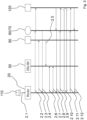
- xDSL access interface 23.1 is implemented in the customer router 20
- xDSL interface 23.1 is activated and at least two xDSL ports 51.1 and 51.2 are implemented in the access network device 50.
- the xDSL interface 23.1 is connected via the xDSL subscriber line 100.1 to xDSL port 51.1 of the DSLAM 50. It is further assumed that the xDSL port 51.1 of the access network device 50 has been deactivated by the control unit 56, for example by using a time scheduler stored in memory 57. For example, the time scheduler triggers the control unit 56 to deactivate xDSL port 51.1 between 9am to 6pm. In addition or alternatively, the control unit 56 may be configured to deactivate xDSL port 51.1 if the customer router 20 is no more in operation since a predefined time interval. Therefore, a timer, which may be integrated in the control unit 56 can trigger the control unit 56 after a predetermined timeout to deactivate xDSL port 51.1.
- step 1.1 this can be initiated by entering a respective request, e.g. by entering a Unified Resource Locater (URL), on the PC 110 and transmitting it to customer router 20.
- the control unit 26 may be configured to interpret the respective request as an Internet session initiation request.
- the control unit 26 is caused at step 1.2 to generate and transmit a request message for activating the deactivated xDSL port 51.1 via its LPWAN interface 25 and the LPWAN network 40 to the LPWAN interface 93 of the network device 90 which belongs to the ISP network 80.
- the network device 90 may acknowledge receipt of the request message and generates in response to the request message received at step 1.2 an xDSL port activating signal.
- the network device 20 transmits the xDSL port activating signal generated at step 1.3 via its communication interface 91 to the communication interface 55 of the access network device 50.
- the access network device 50 is configured to activate the xDSL port 51.1. It is assumed, that the xDSL access interface 23.1 of the customer router 20 is activated or, for example, has been activated by the control unit 26 in response to the Internet session initiation request entered by the user at the PC 110.
- a DSL training procedure e.g. a supervectoring training procedure
- a DSL training procedure may be started in a known manner between the customer router 20 and the access network device 50.
- the xDSL subscriber line 100.1 is available for data transmission and for example a Real Time Protocol (RTP) data traffic session can be established at step 1.6 using the xDSL subscriber line 100.1.
- RTP Real Time Protocol
- the DSLAM 50 may be configured to inform the IMS 60 and the server 70, respectively, of the fact, that xDSL subscriber line 100.1 is now available for data transmission.
- the server 70 may be configured to control transmission of data and/or signaling messages destined for the PC 110 via its communication interface 71 to communication interface 54 of the DSLAM 50, which in turn may forward the data and/or signaling messages to the customer router 20 using the xDSL subscriber line 100.1.
- step 1.2 i.e. generating and transmitting a request message for activating the deactivated xDSL port 51.1, may be triggered if the customer router 20 and in particular the motion sensor 28 detects a motion of the user.
- the control unit 26 may be configured to generate and transmit a respective request message for activating the deactivating xDSL port 51.1 in response to a respective output of the motion sensor 28, which may be electrically connected to the control unit 26.
- the xDSL access interface 23.1 of the customer router 20 can stay activated all the time or deactivated in response to a time scheduler stored for example in memory 27 of the customer router 20 or in response to at least one predefined event which may be a predetermined signal entered by the user on the PC 110 or automatically generated by the PC 110, indicating for example the termination of a session.
- the user of the PC 110 wants to establish a VoIP session to the SIP capable end device 120 using the known SIP protocol as mentioned above while the xDSL port 51.1 is currently deactivated.
- DSLAM 50 and/or customer router 20 are configured to inform the IP-based communication subsystem 60 and the server 70, respectively, that xDSL port 51.1 associated with xDSL subscriber line 100.1 is currently deactivated so that signaling messages have to be exchanged between the customer router 20 and the server 70 using the LPWAN network 40 instead of the xDSL subscriber line 100.1.
- the user may enter a respective request on the PC 110 which in turn generates in response to the request a respective invite message which is forwarded to the router 20.
- the control unit 26 is configured to cause the customer router 20 to transmit, at step 2.2, the invite message via its LPWAN interface 25 and the LPWAN network 40 to the IP-based communication subsystem 60 and the server 70, respectively.
- the server 70 may function as a SIP server configured to forward the invite message to the end device 120 in a known manner.
- the customer router 20 generates in response the invite message received from PC 110 a request message for activating the deactivated xDSL port 51.1 of the access network device 50 and transmits the request message via its LPWAN interface 25 over the LPWAN network 40 to the LPWAN interface 93 of the network device 90.
- the IP-based communication subsystem 60 and in particular the server 70 may transmit, at step 2.4, a 180 ringing message via the LPWAN network 40 to the LPWAN interface 25 of the customer router 20.
- the network device 90 generates an xDSL port activating signal in response to the request message received from the customer router 20 and transmits it to the access network device 50.
- the access network device 50 activates in response to the received xDSL port activating signal its xDSL port 51.1.
- an xDSL training procedure may be executed between customer router 20 and access network device 50 at step 2.6.
- the xDSL training is finished at step 2.7 the xDSL subscriber line 100.1 is available for data transmission between the customer router 20 and the DSLAM 50.
- a 200 OK message generated by end device 120 can be transmitted via the server 70 using its communication interface 71 to communication interface 54 of the DSLAM 50 and further via the xDSL subscriber line 100.1 and the customer router 20 to the PC 110.
- an ACK (Acknowledge) message may be transmitted from the PC 110 via customer router 20, xDSL subscriber line 100.1 and server 70 to the end device 120.
- a Real Time Protocol (RTP) data traffic session can be established using the xDSL subscriber line 100.1.
- RTP Real Time Protocol
- the DSLAM 50 may be configured to inform the IMS 60 and the server 70, respectively, of the fact, that xDSL subscriber line 100.1 is now available for data transmission.
- the server 70 may be configured to control transmission of data and/or signaling messages destined for the PC 110 via its communication interface 71 to communication interface 54 of the DSLAM 50, which in turn may forward the data and/or signaling messages to the customer router 20 using the xDSL subscriber line 100.1.
- a Bye message is transmitted, at step 2.11, from the PC 110 over customer router 20, xDSL subscriber line 100.1, DSLAM 50, server 70 and further to end device 120.
- a 200 OK message is transmitted from end device 120 via server 70, DSLAM 50, xDSL subscriber line 100.1, customer router 20 to PC 110.
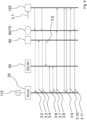
- end device 120 will initiate a VoIP session to the user of PC 110, while xDSL subscriber line 100.1 and xDSL port 51.1, respectively, is currently deactivated. It is further assumed, that DSLAM 50 and/or customer router 20 are configured to inform the IP-based communication subsystem 60 and the server 70, respectively, that xDSL port 51.1 associated with xDSL subscriber line 100.1 is currently deactivated so that signaling messages have to be exchanged between the customer router 20 and the server 70 using the LPWAN network 40 instead of the xDSL subscriber line 100.1.
- the user may now enter, for example, the calling number of the user of PC 110 on its end device 120.
- end device 120 generates at step 3.2 an invite message and transmit it to the server 70, which in turn forwards the invite message via the LPWAN interface 73 and the LPWAN network 40 to the customer router 40 and further to PC 110.
- the customer router 20 generates in response the invite message received from end device 120 a request message for activating the deactivated xDSL port 51.1 of the access network device 50 and transmits the request message via its LPWAN interface 25 over the LPWAN network 40 to the LPWAN interface 93 of the network device 90.
- a 180 ringing message may be transmitted from end device 120 via server 60, LPWAN network 40 to customer router 20 and further to PC 110.
- the network device 90 generates an xDSL port activating signal in response to the request message received at step 3.3 from the customer router 20 and transmits it at step 3.5 to the access network device 50.
- the access network device 50 activates in response to the received xDSL port activating signal its xDSL port 51.1.
- an xDSL training procedure may be executed between customer router 20 and access network device 50 at step 3.6. Once the xDSL training is finished the xDSL subscriber line 100.1 is available at step 3.7 for data transmission between the customer router 20 and the DSLAM 50.
- a Real Time Protocol (RTP) data traffic session can now be established using the xDSL subscriber line 100.1.
- the DSLAM 50 may be configured to inform the IMS 60 and the server 70, respectively, of the fact, that xDSL subscriber line 100.1 is now available for data transmission.
- the server 70 may be configured to control transmission of RTP data traffic and/or signaling messages destined for the PC 110 via its communication interface 71 to communication interface 54 of the DSLAM 50, which in turn may forward the RTP data traffic and/or signaling messages to the customer router 20 using the xDSL subscriber line 100.1.
- a 200 OK message generated by PC 110 can be transmitted via customer router 20, activated xDSL subscriber line 100.1, DSLAM 50, server 70 to end device 120.
- RTP Real time Transmission Protocol
- a Bye message is transmitted, at step 3.10, from the PC 110 over customer router 20, xDSL subscriber line 100.1, DSLAM 50, server 70 to end device 120.
- a 200 OK message is transmitted from end device 120 via server 70, DSLAM 50, xDSL subscriber line 100.1, customer router 20 to PC 110.
Landscapes
- Engineering & Computer Science (AREA)
- Computer Networks & Wireless Communication (AREA)
- Signal Processing (AREA)
- Mobile Radio Communication Systems (AREA)
Claims (16)
- Procédé pour un fonctionnement à économie d'énergie d'une ligne d'abonné (100.1) ayant pour terminaison une interface d'accès (23.1) implémentée dans un routeur client (20) et par un port (51.1) implémenté dans un dispositif de réseau d'accès (50), le routeur client (20) comprenant en outre une interface de réseau sans fil (25) configurée pour communiquer via un réseau sans fil étendu (40) avec un dispositif de réseau (90) en utilisant un protocole de réseau sans fil, dans lequel le procédé comprend les étapes suivantes :a) la désactivation du port (51.1) du dispositif de réseau d'accès (50) en réponse à un planificateur de temps et/ou en réponse à un événement prédéfini, qui est détecté par le dispositif de réseau d'accès (50) ;b) l'activation du port (51.1) désactivé à l'étape a) enb1) transmettant, par le routeur client (20), un message de requête d'activation du port désactivé (51.1) du dispositif de réseau d'accès (50) via son interface de réseau sans fil (25) au dispositif de réseau (90) ;b2) générant, au niveau du dispositif de réseau (90), un signal d'activation de port en réponse au message de requête de l'étape b1) ;b3) transmettant, par le dispositif de réseau (90), le signal d'activation de port généré à l'étape b2) au dispositif de réseau d'accès (50), etb4) activant, par le dispositif de réseau d'accès (50), le port désactivé à l'étape a) de sorte que la ligne d'abonné (100.1) devienne disponible pour la transmission de données entre le routeur client (20) et le dispositif de réseau d'accès (50),dans lequel le réseau sans fil étendu (40) est un réseau radio étendu à faible puissance, LPWAN, et l'interface de réseau sans fil (25) du routeur client (20) est une interface de réseau radio de faible puissance configurée pour communiquer via le réseau radio étendu de faible puissance LPWAN (40) à l'aide d'un protocole de réseau étendu de faible puissance.
- Procédé selon la revendication 1,
dans lequel l'événement prédéfini à l'étape a) est un comportement se basant sur l'utilisateur, qui est détecté par le dispositif de réseau d'accès (50). - Procédé selon la revendication 2,
dans lequel le comportement se basant sur l'utilisateur comprend la fin d'une session Internet ou d'une session VoIP. - Procédé selon l'une quelconque des revendications précédentes,dans lequel l'étape a) comprend l'étape de désactivation de l'interface d'accès (23.1) du routeur client (20), etdans lequel l'étape b) comprend en outre l'étape b4) d'activation de l'interface d'accès (23.1) du routeur client (20) .
- Procédé selon l'une quelconque des revendications précédentes, comprenant en outre l'étape de transmission de messages de signalisation via l'interface de réseau sans fil (25) du routeur client (20) à un sous-système de communication basé sur IP (60) qui fournit des services multimédias et/ou recevoir, au niveau de l'interface de réseau sans fil (25) du routeur client (20), des messages de signalisation provenant du sous-système de communication basé sur IP (60), dans lequel les messages de signalisation peuvent être des messages de protocole d'initiation de session, SIP.
- Procédé selon l'une quelconque des revendications précédentes,
dans lequel l'étape b1) comprend l'étape de transmission du message de requête en réponse à un planificateur de temps et/ou en réponse à un événement prédéfini. - Procédé selon les revendications 5 et 6,
dans lequel l'étape b1) comprend l'étape de transmission du message de requête en réponse à un message de signalisation transmis via l'interface de réseau sans fil (25) du routeur client (20) au sous-système de communication basé sur IP (60) ou en réponse à un message de signalisation reçu, au niveau de l'interface de réseau sans fil (25) du routeur client (20), à partir du sous-système de communication basé sur IP (60). - Procédé selon l'une quelconque des revendications précédentes,
dans lequel l'interface d'accès (23.1) du routeur client (20) est implémentée comme étant une interface d'accès xDSL ou comme étant une interface d'accès optique, dans lequel la ligne d'abonné (100.1) est une ligne d'abonné xDSL ou une fibre optique et dans lequel le port (51.1) du dispositif de réseau d'accès (50) est un port xDSL ou un port optique. - Système de communication (10) pour permettre un fonctionnement à économie d'énergie d'une ligne d'abonné (100.1), comprenant :- un réseau sans fil étendu (40),- un dispositif de réseau (90) ayant une interface de communication (91) et une interface de réseau sans fil (93) configurée pour communiquer via le réseau sans fil étendu (40),- un routeur client (20) ayant une première interface d'accès (23.1) et une interface de réseau sans fil (25) configurée pour communiquer via le réseau sans fil étendu (40) avec le dispositif de réseau (90),- un dispositif de réseau d'accès (50) ayant un premier port (51.1) et une interface de communication (55) configurée pour communiquer avec l'interface de communication (91) du dispositif de réseau (90),- une première ligne d'abonné (100.1) ayant pour terminaison la première interface d'accès (23.1) du routeur client (20) et par le premier port (51.1) du dispositif de réseau d'accès (50), dans lequelle dispositif de réseau d'accès (50) est configuré pour désactiver le premier port (51.1) constituant la terminaison de la première ligne d'abonné (100.1) en réponse à un planificateur de temps et/ou en réponse à un événement prédéfini, dans lequel le dispositif de réseau d'accès (50) est configuré pour détecter l'événement prédéfini, dans lequelle routeur client (20) est configuré pour transmettre un message de requête pour activer le premier port (51.1) du dispositif de réseau d'accès (50) via son interface de réseau sans fil (25) au dispositif de réseau (90), dans lequelle dispositif de réseau (90) est configuré pour générer un signal d'activation de port en réponse au message de requête reçu à partir du routeur client (20) et pour transmettre, via son interface de communication (91), le signal d'activation de port au dispositif de réseau d'accès (50), et dans lequelle dispositif de réseau d'accès (50) est configuré pour activer le premier port (51.1) constituant la terminaison de la première ligne d'abonné (100.1), de sorte que la ligne d'abonné (100.1) devienne disponible pour la transmission de données entre le routeur client (20) et le dispositif de réseau d'accès 50), dans lequell'interface de réseau sans fil (25) du routeur client (20) et l'interface de réseau sans fil (93) du dispositif de réseau (90) sont chacune une interface de réseau radio de faible puissance utilisant un protocole de réseau étendu de faible puissance, et dans lequel le réseau sans fil étendu (40) est un réseau radio étendu de faible puissance, LPWAN.
- Système de communication selon la revendication 9, dans lequel le routeur client (20) est configuré pour transmettre des messages de signalisation via son interface de réseau sans fil (25) à un sous-système de communication basé sur IP (60, 70) configuré pour fournir des services multimédias, le système de communication basé sur IP (60, 70) ayant une interface de réseau sans fil (73) configurée pour recevoir des messages de signalisation à partir du routeur client (20), dans lequel le sous-système de communication basé sur IP (60, 70) est en outre configuré pour transmettre des messages de signalisation via son interface de réseau sans fil (73) au routeur client (20), qui est configuré pour recevoir les messages de signalisation du sous-système de communication basé sur IP (60, 70), dans lequel les messages de signalisation peuvent être des messages de protocole d'initiation de session (SIP).
- Système de communication selon l'une quelconque des revendications 9 et 10, comprenant en outreune deuxième ligne d'abonné (100.2), dans lequelle routeur client (20) comprend une deuxième interface d'accès (23.2), dans lequel le dispositif de réseau d'accès (50) comprend un deuxième port (51.2), dans lequella deuxième ligne d'abonné (100.2) a pour terminaison la deuxième interface d'accès (23.2) du routeur client (20) et par le deuxième port (51.2) du dispositif de réseau d'accès (50), dans lequelle dispositif de réseau d'accès (50) est configuré pour désactiver le deuxième port (51.2) constituant la terminaison de la deuxième ligne d'abonné (100.2), dans lequelle routeur client (20) est configuré pour transmettre un message de requête pour activer le deuxième port (51.2) du dispositif de réseau d'accès (50) via son interface de réseau sans fil (25) au dispositif de réseau (90), dans lequelle dispositif de réseau (90) est configuré pour générer un signal d'activation de port par rapport au deuxième port (51.2) en réponse au message de requête reçu à partir du routeur client (20) et pour transmettre, via son interface de communication (91), le signal d'activation de port par rapport au deuxième port (51.2) au dispositif de réseau d'accès (50), et dans lequelle dispositif de réseau d'accès (50) est configuré pour activer le deuxième port (51.2) constituant la terminaison de la deuxième ligne d'abonné (100.2).
- Système de communication selon l'une quelconque des revendications 9 à 11, dans lequel la première et/ou la deuxième interface d'accès (23.1, 23.2) du routeur client (20) sont implémentées chacune comme étant une interface d'accès xDSL ou comme étant une interface d'accès optique, dans lequel la première et/ou la deuxième ligne d'abonné (100.1, 100.2) sont chacune une ligne d'abonné xDSL ou une fibre optique et dans lequel le premier et/ou le deuxième port (51.1, 51.2) du dispositif de réseau d'accès (50) sont chacun un port xDSL ou un port optique.
- Système de communication selon les revendications 11 et 12,
dans lequel
le routeur client (20) est configuré pour désactiver et pour activer la première interface d'accès (23.1) et/ou la deuxième interface d'accès (23.2). - Système de communication selon l'une quelconque des revendications 9 à 13, dans lequelle routeur client (20) comprend une interface d'accès haut débit sans fil (22), et dans lequelle routeur client (20) est configuré pour établir une session Internet via l'interface d'accès haut débit sans fil (22) .
- Système de communication selon l'une quelconque des revendications 9 à 14,dans lequel le routeur client (20) est un dispositif d'accès intégré, IAD, etdans lequel le dispositif de réseau d'accès (50) est un multiplexeur d'accès de ligne d'abonné numérique, xDSLAM ou un noeud d'accès multi-service, MSAN.
- Système de communication selon l'une quelconque des revendications 9 à 15,dans lequel le routeur client (20) comprend un capteur de mouvement (28) qui est configuré pour détecter un mouvement d'un utilisateur, dans lequelle routeur client (20) est configuré pour générer et transmettre le message de requête d'activation du premier port (51.1) en réponse à une sortie respective du capteur de mouvement (28) via son interface de réseau sans fil (25) au dispositif de réseau (90).
Priority Applications (1)
| Application Number | Priority Date | Filing Date | Title |
|---|---|---|---|
| EP20194703.3A EP3965408B1 (fr) | 2020-09-04 | 2020-09-04 | Procédé et système de communication pour une opération d'économie d'énergie d'une ligne d'abonné |
Applications Claiming Priority (1)
| Application Number | Priority Date | Filing Date | Title |
|---|---|---|---|
| EP20194703.3A EP3965408B1 (fr) | 2020-09-04 | 2020-09-04 | Procédé et système de communication pour une opération d'économie d'énergie d'une ligne d'abonné |
Publications (2)
| Publication Number | Publication Date |
|---|---|
| EP3965408A1 EP3965408A1 (fr) | 2022-03-09 |
| EP3965408B1 true EP3965408B1 (fr) | 2024-01-10 |
Family
ID=72422075
Family Applications (1)
| Application Number | Title | Priority Date | Filing Date |
|---|---|---|---|
| EP20194703.3A Active EP3965408B1 (fr) | 2020-09-04 | 2020-09-04 | Procédé et système de communication pour une opération d'économie d'énergie d'une ligne d'abonné |
Country Status (1)
| Country | Link |
|---|---|
| EP (1) | EP3965408B1 (fr) |
Family Cites Families (4)
| Publication number | Priority date | Publication date | Assignee | Title |
|---|---|---|---|---|
| US7567665B2 (en) * | 2002-04-29 | 2009-07-28 | Adc Dsl Systems, Inc. | Function for controlling line powered network element |
| US10225009B2 (en) * | 2016-07-01 | 2019-03-05 | Adtran, Inc. | Broadband access devices having a radio link |
| FR3086482B1 (fr) * | 2018-09-25 | 2020-09-11 | Sagemcom Energy & Telecom Sas | Procede de gestion d’itinerance par transfert multi-reseaux |
| CN110677745B (zh) * | 2019-09-20 | 2023-10-24 | 广东电网有限责任公司广州供电局 | 配电装置、系统和方法 |
-
2020
- 2020-09-04 EP EP20194703.3A patent/EP3965408B1/fr active Active
Also Published As
| Publication number | Publication date |
|---|---|
| EP3965408A1 (fr) | 2022-03-09 |
Similar Documents
| Publication | Publication Date | Title |
|---|---|---|
| KR100728280B1 (ko) | Sip를 이용한 통신 시스템에서 호 해제 요청/응답메시지를 이용한 네트워크 상태 관리 방법 | |
| US8027335B2 (en) | Multimedia access device and system employing the same | |
| US20080267169A1 (en) | Method and system for remote diagnosis of a device over a communication network | |
| JP4433206B2 (ja) | コネクションを確立し維持する方法 | |
| EP3965408B1 (fr) | Procédé et système de communication pour une opération d'économie d'énergie d'une ligne d'abonné | |
| EP1641311B1 (fr) | Mécanismes d'isolation d'erreurs pour un service d'émulation POTS sur une plate-forme FTTx | |
| KR101080383B1 (ko) | 브이오아이피 호설정 방법 및 이를 수행하는 브이오아이피 통신 시스템 | |
| Cisco | Configuring DDR | |
| Cisco | T | |
| Cisco | Configuring Dial-on-Demand Routing | |
| Cisco | Configuring Dial-on-Demand Routing | |
| Cisco | Configuring Dial-on-Demand Routing | |
| Cisco | Configuring Dial-on-Demand Routing | |
| Cisco | Voice Over IP for the Cisco AS5800 Commands | |
| Cisco | Configuring Dial-on-Demand Routing | |
| Cisco | Configuring Dial-on-Demand Routing | |
| Cisco | Configuring Dial-on-Demand Routing | |
| Cisco | Configuring DDR | |
| Cisco | R | |
| Cisco | Configuring DDR | |
| Cisco | Cisco IOS Voice, Video, and Fax Commands: Si through Z | |
| Cisco | Configuring DDR | |
| Cisco | Configuring DDR | |
| Cisco | Configuring DDR | |
| Cisco | Configuring DDR |
Legal Events
| Date | Code | Title | Description |
|---|---|---|---|
| PUAI | Public reference made under article 153(3) epc to a published international application that has entered the european phase |
Free format text: ORIGINAL CODE: 0009012 |
|
| STAA | Information on the status of an ep patent application or granted ep patent |
Free format text: STATUS: THE APPLICATION HAS BEEN PUBLISHED |
|
| AK | Designated contracting states |
Kind code of ref document: A1 Designated state(s): AL AT BE BG CH CY CZ DE DK EE ES FI FR GB GR HR HU IE IS IT LI LT LU LV MC MK MT NL NO PL PT RO RS SE SI SK SM TR |
|
| STAA | Information on the status of an ep patent application or granted ep patent |
Free format text: STATUS: REQUEST FOR EXAMINATION WAS MADE |
|
| 17P | Request for examination filed |
Effective date: 20220614 |
|
| RBV | Designated contracting states (corrected) |
Designated state(s): AL AT BE BG CH CY CZ DE DK EE ES FI FR GB GR HR HU IE IS IT LI LT LU LV MC MK MT NL NO PL PT RO RS SE SI SK SM TR |
|
| GRAP | Despatch of communication of intention to grant a patent |
Free format text: ORIGINAL CODE: EPIDOSNIGR1 |
|
| STAA | Information on the status of an ep patent application or granted ep patent |
Free format text: STATUS: GRANT OF PATENT IS INTENDED |
|
| RIC1 | Information provided on ipc code assigned before grant |
Ipc: H04L 12/12 20060101ALI20230714BHEP Ipc: H04L 12/28 20060101ALI20230714BHEP Ipc: H04L 12/10 20060101ALI20230714BHEP Ipc: H04M 11/06 20060101AFI20230714BHEP |
|
| INTG | Intention to grant announced |
Effective date: 20230814 |
|
| GRAS | Grant fee paid |
Free format text: ORIGINAL CODE: EPIDOSNIGR3 |
|
| GRAA | (expected) grant |
Free format text: ORIGINAL CODE: 0009210 |
|
| STAA | Information on the status of an ep patent application or granted ep patent |
Free format text: STATUS: THE PATENT HAS BEEN GRANTED |
|
| AK | Designated contracting states |
Kind code of ref document: B1 Designated state(s): AL AT BE BG CH CY CZ DE DK EE ES FI FR GB GR HR HU IE IS IT LI LT LU LV MC MK MT NL NO PL PT RO RS SE SI SK SM TR |
|
| REG | Reference to a national code |
Ref country code: GB Ref legal event code: FG4D |
|
| REG | Reference to a national code |
Ref country code: CH Ref legal event code: EP |
|
| REG | Reference to a national code |
Ref country code: DE Ref legal event code: R096 Ref document number: 602020024125 Country of ref document: DE |
|
| REG | Reference to a national code |
Ref country code: IE Ref legal event code: FG4D |