EP3965365B1 - Basismodul eines netzwerkaufbaus sowie netzwerkaufbau und verfahren zum konfigurieren eines erweiterungsmoduls des netzwerkaufbaus - Google Patents
Basismodul eines netzwerkaufbaus sowie netzwerkaufbau und verfahren zum konfigurieren eines erweiterungsmoduls des netzwerkaufbaus Download PDFInfo
- Publication number
- EP3965365B1 EP3965365B1 EP21182338.0A EP21182338A EP3965365B1 EP 3965365 B1 EP3965365 B1 EP 3965365B1 EP 21182338 A EP21182338 A EP 21182338A EP 3965365 B1 EP3965365 B1 EP 3965365B1
- Authority
- EP
- European Patent Office
- Prior art keywords
- module
- communication
- network structure
- logic unit
- extension
- Prior art date
- Legal status (The legal status is an assumption and is not a legal conclusion. Google has not performed a legal analysis and makes no representation as to the accuracy of the status listed.)
- Active
Links
Images


Classifications
-
- H—ELECTRICITY
- H04—ELECTRIC COMMUNICATION TECHNIQUE
- H04L—TRANSMISSION OF DIGITAL INFORMATION, e.g. TELEGRAPHIC COMMUNICATION
- H04L67/00—Network arrangements or protocols for supporting network services or applications
- H04L67/01—Protocols
- H04L67/12—Protocols specially adapted for proprietary or special-purpose networking environments, e.g. medical networks, sensor networks, networks in vehicles or remote metering networks
- H04L67/125—Protocols specially adapted for proprietary or special-purpose networking environments, e.g. medical networks, sensor networks, networks in vehicles or remote metering networks involving control of end-device applications over a network
-
- H—ELECTRICITY
- H04—ELECTRIC COMMUNICATION TECHNIQUE
- H04L—TRANSMISSION OF DIGITAL INFORMATION, e.g. TELEGRAPHIC COMMUNICATION
- H04L12/00—Data switching networks
- H04L12/28—Data switching networks characterised by path configuration, e.g. LAN [Local Area Networks] or WAN [Wide Area Networks]
- H04L12/40—Bus networks
- H04L12/40006—Architecture of a communication node
- H04L12/40045—Details regarding the feeding of energy to the node from the bus
-
- G—PHYSICS
- G06—COMPUTING OR CALCULATING; COUNTING
- G06F—ELECTRIC DIGITAL DATA PROCESSING
- G06F13/00—Interconnection of, or transfer of information or other signals between, memories, input/output devices or central processing units
- G06F13/38—Information transfer, e.g. on bus
- G06F13/40—Bus structure
- G06F13/4004—Coupling between buses
- G06F13/4022—Coupling between buses using switching circuits, e.g. switching matrix, connection or expansion network
-
- G—PHYSICS
- G06—COMPUTING OR CALCULATING; COUNTING
- G06F—ELECTRIC DIGITAL DATA PROCESSING
- G06F13/00—Interconnection of, or transfer of information or other signals between, memories, input/output devices or central processing units
- G06F13/38—Information transfer, e.g. on bus
- G06F13/40—Bus structure
- G06F13/4063—Device-to-bus coupling
- G06F13/4068—Electrical coupling
- G06F13/4072—Drivers or receivers
-
- H—ELECTRICITY
- H04—ELECTRIC COMMUNICATION TECHNIQUE
- H04L—TRANSMISSION OF DIGITAL INFORMATION, e.g. TELEGRAPHIC COMMUNICATION
- H04L41/00—Arrangements for maintenance, administration or management of data switching networks, e.g. of packet switching networks
- H04L41/08—Configuration management of networks or network elements
- H04L41/0803—Configuration setting
-
- H—ELECTRICITY
- H04—ELECTRIC COMMUNICATION TECHNIQUE
- H04L—TRANSMISSION OF DIGITAL INFORMATION, e.g. TELEGRAPHIC COMMUNICATION
- H04L41/00—Arrangements for maintenance, administration or management of data switching networks, e.g. of packet switching networks
- H04L41/08—Configuration management of networks or network elements
- H04L41/0876—Aspects of the degree of configuration automation
- H04L41/0886—Fully automatic configuration
-
- H—ELECTRICITY
- H05—ELECTRIC TECHNIQUES NOT OTHERWISE PROVIDED FOR
- H05B—ELECTRIC HEATING; ELECTRIC LIGHT SOURCES NOT OTHERWISE PROVIDED FOR; CIRCUIT ARRANGEMENTS FOR ELECTRIC LIGHT SOURCES, IN GENERAL
- H05B47/00—Circuit arrangements for operating light sources in general, i.e. where the type of light source is not relevant
- H05B47/10—Controlling the light source
- H05B47/165—Controlling the light source following a pre-assigned programmed sequence; Logic control [LC]
-
- H—ELECTRICITY
- H05—ELECTRIC TECHNIQUES NOT OTHERWISE PROVIDED FOR
- H05B—ELECTRIC HEATING; ELECTRIC LIGHT SOURCES NOT OTHERWISE PROVIDED FOR; CIRCUIT ARRANGEMENTS FOR ELECTRIC LIGHT SOURCES, IN GENERAL
- H05B47/00—Circuit arrangements for operating light sources in general, i.e. where the type of light source is not relevant
- H05B47/10—Controlling the light source
- H05B47/175—Controlling the light source by remote control
- H05B47/18—Controlling the light source by remote control via data-bus transmission
-
- H—ELECTRICITY
- H05—ELECTRIC TECHNIQUES NOT OTHERWISE PROVIDED FOR
- H05B—ELECTRIC HEATING; ELECTRIC LIGHT SOURCES NOT OTHERWISE PROVIDED FOR; CIRCUIT ARRANGEMENTS FOR ELECTRIC LIGHT SOURCES, IN GENERAL
- H05B47/00—Circuit arrangements for operating light sources in general, i.e. where the type of light source is not relevant
- H05B47/10—Controlling the light source
- H05B47/175—Controlling the light source by remote control
- H05B47/19—Controlling the light source by remote control via wireless transmission
-
- H—ELECTRICITY
- H05—ELECTRIC TECHNIQUES NOT OTHERWISE PROVIDED FOR
- H05B—ELECTRIC HEATING; ELECTRIC LIGHT SOURCES NOT OTHERWISE PROVIDED FOR; CIRCUIT ARRANGEMENTS FOR ELECTRIC LIGHT SOURCES, IN GENERAL
- H05B47/00—Circuit arrangements for operating light sources in general, i.e. where the type of light source is not relevant
- H05B47/10—Controlling the light source
- H05B47/175—Controlling the light source by remote control
- H05B47/198—Grouping of control procedures or address assignation to light sources
- H05B47/1985—Creation of lighting zones or scenes
-
- H—ELECTRICITY
- H05—ELECTRIC TECHNIQUES NOT OTHERWISE PROVIDED FOR
- H05B—ELECTRIC HEATING; ELECTRIC LIGHT SOURCES NOT OTHERWISE PROVIDED FOR; CIRCUIT ARRANGEMENTS FOR ELECTRIC LIGHT SOURCES, IN GENERAL
- H05B47/00—Circuit arrangements for operating light sources in general, i.e. where the type of light source is not relevant
- H05B47/10—Controlling the light source
- H05B47/175—Controlling the light source by remote control
- H05B47/198—Grouping of control procedures or address assignation to light sources
- H05B47/199—Commissioning of light sources
Definitions
- the present disclosure relates generally to network assemblies. More particularly, the present disclosure relates to electronic network assemblies with expandable functionality.
- Network devices are also known that can participate in device networks or IoT (Internet of Things), such as lights or lighting devices in a light management system or LMS (Light Management System).
- IoT Internet of Things
- LMS Light Management System
- the connection of a light to an IoT network or LMS can be implemented using additional, network-specific hardware and software units, which can basically be different for each network, as shown for example in WO 2018/029518 A1 is shown.
- network devices and lights are constantly being upgraded to meet modern requirements for controllability and network capability.
- the additional units that are already available cannot simply be used for other networks or other purposes, which can lead to high costs and high environmental impacts.
- An object of the embodiments of the present disclosure is to provide a network structure for network devices which can be equipped with additional functionalities in a flexible and cost-effective manner.
- a basic module according to claim 1 is provided.
- the communication bus can be designed in particular to transmit data or signals between the logic unit and the expansion modules.
- the communication bus is designed to supply one or more expansion modules with electrical energy.
- the communication bus can in particular comprise signal lines for serial communication or transmission of messages and/or supply lines for supplying energy to the expansion modules or peripherals.
- the communication bus is designed as part of the base module.
- the communication bus can be designed to be connected to a large number of functional devices and/or communication modules as expansion modules in order to provide desired functionalities.
- the logic unit represents in particular the central component or node via which, in particular, all network communication can take place.
- the logic or the logic unit therefore plays the central role in such a modular network structure.
- the logic unit can forward, process and/or change information in accordance with the intended operating scenarios.
- the logic unit can in particular comprise a microcontroller with a processor for data processing, with a memory unit for storing data and machine-readable codes for the processor and with an interface for connecting the logic unit to the communication bus.
- the logic unit or the microcontroller can also comprise one or more further interfaces, in particular for configuring digital inputs and outputs and/or for translating measurement signals. Configuring the logic unit to carry out certain actions in this context means that in order to carry out these actions, corresponding machine-readable instructions for the processor are stored in the memory unit of the logic unit.
- the logic unit can be configured in such a way that communication via the communication bus between the logic unit and the extension modules can take place, in particular exclusively, via a system-internal or proprietary communication protocol.
- the system-internal communication protocol can in particular make it difficult or impossible for unauthorized access to the communication bus of the network structure.
- the use of the system-internal or proprietary communication protocol can make it difficult or impossible for unauthorized extension modules to be connected to the base module.
- the communication bus can thus be used as a protected, proprietary interface or ILB (Intra Luminaire Bus) for Exchange of data or messages between the logic unit and the expansion modules or peripherals.
- ILB Intra Luminaire Bus
- the functional devices or peripherals can in particular include sensors or various sensors, drivers, in particular LED drivers, push buttons and/or other devices.
- a functional device can be designed to detect or control the amount of light generated by the lamp.
- a lamp can in particular have one or more light sources.
- a lamp can include a light source for generating indirect light, such as in a diffusely lit lighting device, and a light source for generating direct light, such as in a light spotlight.
- the amount of light can be controlled directly via the logic unit or via the LMS in which the lamp is integrated.
- the functional devices can also be used to record and/or transmit data to the LMS.
- the functional devices can include CO2 and/or temperature sensors that record or monitor the current CO2 concentration or temperature value and provide the recorded data, for example for the purpose of building maintenance or maintenance.
- this information can be used to optimize energy consumption or increase the efficiency of operational processes.
- the one or more communication modules may comprise a module designed for wireless communication.
- the extension module may in particular comprise a ZigBee, Bluetooth, DALI interface.
- ZigBee ® is a registered trademark of the ZigBee Alliance.
- Bluetooth ® is a registered trademark of the Bluetooth Special Interest Group.
- DALI ® Digital Addressable Lighting Interface
- the communication module can be designed in particular to act as an interpreter between the logic unit and the LMS by communicating with the LMS using a standard protocol and communicating with the logic unit using the internal or proprietary protocol of the communication bus.
- An LMS enables customers to control different lights individually or in groups and to define lighting scenes from simple to complex.
- An extension module can also represent a communication module and a functional device at the same time, for example a ZigBee module with an integrated PIR sensor (Passive Infrared Sensor).
- the network structure around the logic unit as a central unit or "core module” can be set up or expanded in a modular and flexible manner.
- the basic module can therefore be used to create an interconnect system that allows the customer to determine the functionality, complexity and costs of operating devices or lights and to adapt them to their own needs.
- the basic module represents a design platform that allows functional devices to be used freely and flexibly, if necessary in compliance with any norms, standards and requirements in the desired device network or lighting management system.
- the logic unit can be configured to search for an expansion module connected to the communication bus via the communication bus. This search function enables the logic unit to determine whether one or another expansion module has been connected to the communication module in order to react accordingly if necessary.
- the logic unit can be configured to configure an expansion module for the communication bus if the search shows that the expansion module is connected to the communication bus. In particular, the logic unit can automatically configure a communication module connected to the communication bus as intended, so that, for example, by configuring a communication module, the network structure is automatically initialized for an LMS.
- the logic unit has a further interface, in particular a plug-and-play interface, for connecting a plug-and-play functional unit or a functional device that can be directly controlled by the logic unit via control signals.
- a plug-and-play interface for connecting a plug-and-play functional unit or a functional device that can be directly controlled by the logic unit via control signals.
- an LED driver without microcontroller-based intelligence can be connected to the plug-and-play interface and controlled directly by the logic unit.
- the LED driver variables set at the factory can be stored directly in the logic unit.
- Intelligent LED drivers that have their own microcontrollers can be connected to the communication bus or ILB interface.
- a network structure is provided with a base module according to the first aspect.
- the network structure comprises at least one expansion module, in particular one or more functional devices and/or communication modules, for expanding the functions or for providing the functions of the network structure, and a communication bus for providing communication between the logic unit the base module and one or more extension modules.
- the modular design of the network structure makes it easy to expand or retrofit the network structure with expansion modules.
- the network structure can comprise at least one light source, in particular at least one LED light source, and at least one driver, in particular an LED driver, for driving the at least one light source, wherein the at least one driver can be designed as a functional device that can be connected to the communication bus.
- the network structure can be designed as a light.
- Such a light can be equipped with additional functions in a simple manner by connecting additional expansion modules, such as additional functional devices and/or communication modules, to the communication bus.
- the network structure includes a plug-and-play LED driver that is connected to the logic unit's plug-and-play interface and can be controlled directly by the logic unit. This means that simple LED drivers that are not able to communicate with the logic unit via the system's internal communication bus can be controlled directly via the plug-and-play interface.
- the at least one extension module can comprise at least one communication module for connecting the network structure, in particular via a standardized protocol, to a network system or LMS.
- the at least one communication module can be used as a communication module for wireless Be trained in communication with a network system or LMS.
- a method for configuring an extension module of a network structure according to claim 6 is provided.
- the method may comprise querying whether the extension module found during the search is a communication module, wherein the extension module may be determined to represent a functional device present in the network structure by the communication module in a network if the query shows that the extension module found during the search is a communication module.
- a communication module connected to the communication bus can thus be automatically configured to connect the network structure to the network, in particular LMS.
- Representation can include notifying the communication module about the type of functional device present.
- the information about the type of functional device can be automatically passed on to the network, in particular LMS, via the communication module.
- the method can also include sending network-relevant or network-necessary factory settings of the functional device to the communication module.
- the information about the factory settings of the functional device can be automatically forwarded to the network, in particular LMS, via the communication module.
- the network structure described above allows the lights to be calibrated subsequently, particularly after they have been installed as intended, in cases where the network structure includes an extension module designed as a light.
- the calibration data can be recorded on a light of the same type and transferred to the network structure via an extension module designed as a communication module, particularly one that is online-capable. This means that such lights can be calibrated subsequently, regardless of the installation and manufacturer.
- Fig. 1 shows schematically a network structure or interconnect according to an embodiment.
- the network structure 1 comprises a base module 2 with a logic unit 3, a communication bus 4 and extension modules 5, which are in a functional connection with the logic unit 3.
- One extension module 5 in the form of a Zigbee module 6 and one extension module 5 in the form of a sensor module 7 are connected to the logic unit 3 via the communication bus 4.
- One extension module 5 in the form of an LED driver 8 is connected to the logic unit 3 via a Interface 9 connected to the logic unit 3.
- Fig. 1 also shows a light source 10 which is electrically connected to the LED driver 8 and can be controlled by the LED driver 8.
- the Zigbee module 6 is designed to be connected to an LMS 20 (in Fig. 1 symbolically represented).
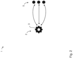
- Fig. 2 shows a schematic of a network structure according to another embodiment.
- the network structure 1 or interconnect of the Fig. 2 comprises a base module 2 with a logic unit 3 and extension modules 5, which are functionally connected to the logic unit 3.
- the functional connection between the logic unit 3 and the extension modules 5 is shown schematically by double-sided arrows.
- the extension modules 5 can be both functional devices and communication modules.
- the network structure 1 represents a standalone light, with one of the extension modules 5 being designed as an LED driver for controlling the light of the light.
- the extension modules 5 are similar to Fig. 1 via a communication bus or ILB (in Fig. 2 not shown) to the logic unit 3.
- the logic unit 3 can in particular be configured such that the functional connection or communication via the communication bus between the logic unit 3 and the extension modules 5 can take place via a system-internal or proprietary communication protocol.
- all extension modules 5 are connected to the logic unit 3 exclusively via a proprietary ILB.
- the logic unit 3 has an additional interface, in particular a plug-and-play interface, to which in particular an LED driver can be directly connected.
- the plug-and-play interface can be a protected proprietary Interface so that the use of non-approved or unqualified LED drivers or other extension modules can be prevented.
- the logic unit 3 can be configured such that an LED driver which does not have its own microcontroller-based intelligence can be connected directly to the plug & play interface. In such a case, any variables of the LED driver set at the factory can be saved directly in the logic unit so that the LED driver can be controlled directly by the logic unit 3.
- the connection to the logic unit 3 is possible via the communication bus 4 or ILB.
- the logic unit 3 can be designed to search for extension modules 5 or peripherals via the ILB and to receive, process and send messages to peripherals via the ILB in a standalone mode, in particular without integrating the network structure 1 in an LMS.
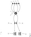
- Fig. 3 shows schematically a network structure according to another embodiment.
- the network structure 1 of the Fig. 3 essentially corresponds to the network structure 1 of the Fig. 2 and additionally has an extension module in the form of a communication module 30, via which the network structure 1 can be connected to an LMS 20 (symbolically shown).
- the further extension modules 5, which are designed as functional devices, are connected to the communication module 30 via the logic unit 3.
- the connection between the functional devices and the communication module 30 can be designed flexibly via the logic unit 3.
- the functional devices can be assigned to the communication module 30 via the logic unit 3 individually, in groups, or not at all.
- the logic unit 3 can be configured in particular to configure a communication module 30 connected to the communication bus 4 after detecting it and to initialize it for participation in a corresponding LMS 20.
- the flow chart of the Fig. 6 below shows the corresponding process flow.
- Fig. 4 shows schematically a network structure according to another embodiment.
- the network structure 1 of the Fig. 4 essentially corresponds to the network structure 1 of the Fig. 3 and additionally has a further communication module 30'.
- the network structure 1 of the Fig. 4 In addition to a first communication module 30, a second communication module 30' has been provided, whereby the network structure 1 can be connected to an LMS 20 (symbolically shown) via the first communication module 30 and the second communication module 30'.
- Fig. 4 The embodiment shown corresponds in particular to the case when the number of functional devices reaches the limit of a communication module for flawless operation in an LMS, after which a further communication module of the same type is attached to the logic.
- the logic unit 3 can in particular be configured to be connected to a multiplicity of communication modules 30, 30' via the communication bus 4 or ILB, so that flawless operation of several functional devices in an LMS can be ensured.
- the logic unit 3 can in particular be configured to assign functional devices to the individual communication modules 30, 30', so that the network structure 1 can be easily scaled by incorporating further functional devices. For example, some expansion modules 5 or functional devices can be assigned to the first communication module 30 and other expansion modules 5' or functional devices can be assigned to the second communication module 30'.
- Fig. 5 shows schematically a network structure according to another embodiment.
- the network structure 1 of the Fig. 5 essentially corresponds to the network structure 1 of the Fig. 4 .
- two different communication modules 30, 30' are used, which can be configured by the logic unit 3.
- the logic unit 3 switches to multi-master mode operation, due to the simultaneous existence of two different LMS 20, 20'.
- the in Figures 1 , 3 , 4 and 5 The network structures described above can be designed to subsequently calibrate a luminaire for more precise colour control and optimised maintenance.
- the measurements can be carried out on luminaires with the same luminaire type provided and the calibration data for the existing installation can be made available as an online update.
- an extension module or peripheral is attached to the structure, or used if necessary, which has an "online update" capability (e.g. ZigBee peripheral).
- This calibration data can in particular contain information about the warmest and coldest colour temperature, the nominal luminous flux and the performance of the luminaire, and/or a Colour Rendering Index (CRI) as well as information about the manufacturer, etc.
- CRI Colour Rendering Index
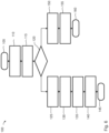
- Fig. 6 shows a flowchart of a method for configuring an expansion module according to an embodiment.
- the method 100 shown for configuring an expansion module or peripheral can be used in particular in one of the network structures according to Figures 1 , 3 , 4 , and 5 According to the Fig. 6
- a search is made in the method step 110 for a peripheral or an extension module 5 connected to the base module 2, in particular via the communication bus 4 or ILB.
- the peripheral or extension module 5 found is configured for the communication bus or ILB.
- the extension module 5 or peripheral is enabled to participate in the communication via the communication bus 4.
- a query step 120 it is queried whether the extension module or peripheral found is a communication module.
- the communication module can be determined in method step 125 to represent a functional device already present in the network structure 1 in an LMS.
- the peripheral or the communication module 30 is then notified of the type of functional device to be represented.
- the factory settings of the functional device required for participation in the LMS are then sent to the communication module 30.
- the peripheral or the communication module found is activated for participation in the LMS. The method 100 for configuring the extension module is then terminated with method step 145.
- the expansion module is recognized as a functional device in method step 150.
- the functional device is initialized and the method ends with method step 145.
- Fig. 7 shows a flow chart of a procedure for calibrating a luminaire.
- the method 200 shown can be carried out in particular for calibrating a luminaire which has an internal architecture according to one of the Figures 1 to 5 According to the network structure shown in Fig. 7
- a query 210 is carried out by the logic unit 3 as to whether a lamp is present or connected to the ILB. If the query 210 results in the presence of a lamp, a lamp, in particular of the same lamp type, is measured for calibration in method step 215.
- method step 220 data for calibration are recorded and in method step 225 the recorded data are transmitted to an online-capable peripheral or communication module of the network structure for calibration.
- step 230 the logic unit 3 is informed of the data received and the control, in particular the color control of the lamp, is adjusted accordingly.
- step 235 the lamp data is made available for the LMS and the method is terminated with method step 240. If the query in step 120 shows that no luminaire, in particular no luminaire with the required luminaire type, is available, a luminaire for measurement is requested in method step 245.
- This calibration option allows customers to minimize the logistical effort associated with commissioning an LMS. This is because the lights are usually calibrated individually with an LED driver in the factory. The lights described here can be purchased flexibly, especially from the desired manufacturers, and only calibrated subsequently, in particular according to the calibration procedure described above.
- the network structures based on the platform design described above offer a number of advantages.
- Such network structures or systems can, for example, be easily scaled up by connecting additional extension modules, in particular functional devices and/or communication modules, to the communication bus or ILB.
- functional devices can be used flexibly, as required, in different networks or LMSs or in a standalone device or luminaire.
- different functional devices can be integrated into an LMS both individually and simultaneously.
- the modularity of the network structure simplifies the change from one, for example outdated, LMS to another, in particular future-proof, LMS without having to discard the existing functional devices.
Landscapes
- Engineering & Computer Science (AREA)
- Computer Networks & Wireless Communication (AREA)
- Theoretical Computer Science (AREA)
- General Engineering & Computer Science (AREA)
- Physics & Mathematics (AREA)
- Signal Processing (AREA)
- Computer Hardware Design (AREA)
- General Physics & Mathematics (AREA)
- Mathematical Physics (AREA)
- Medical Informatics (AREA)
- Automation & Control Theory (AREA)
- General Health & Medical Sciences (AREA)
- Computing Systems (AREA)
- Health & Medical Sciences (AREA)
- Circuit Arrangement For Electric Light Sources In General (AREA)
Description
- Die vorliegende Offenbarung betrifft im Allgemeinen Netzwerkaufbauten. Im Speziellen betrifft die vorliegende Offenbarung elektronische Netzwerkaufbauten mit erweiterbarer Funktionalität.
- Elektronische Vorrichtungen bzw. Betriebsgeräte werden immer komplexer und weisen eine zunehmende Anzahl von Funktionalitäten auf, welche in der Regel durch entsprechende Funktionseinheiten, wie etwa Sensorik, Kommunikationsschnittstellen, intelligente Elektronik, realisiert werden. Es sind ferner Netzwerkgeräte bekannt, die sich in Gerätenetzwerken bzw. IoT (Internet of Things) beteiligen können, wie beispielsweise Leuchten bzw. Leuchtvorrichtungen, in einem Licht-Management-System oder LMS (Light Management System). Insbesondere kann das Anbinden einer Leuchte an ein IoT-Netzwerk bzw. LMS mittels zusätzlicher, netzwerkspezifischer Hardware- und Software-Einheiten realisiert werden, die grundsätzlich für jedes Netzwerk unterschiedlich sein können, wie beispielhaft in
WO 2018/029518 A1 gezeigt wird. Ferner werden Netzwerkgeräte bzw. Leuchten ständig hochgerüstet, um den modernen Anforderungen an Steuerbarkeit und Netzwerkfähigkeit gerecht zu werden. Die bereits vorhandenen Zusatzeinheiten können nicht ohne weiteres für andere Netzwerke bzw. andere Zwecke verwendet werden, was zu hohen Kosten und hohen Umweltbelastungen führen kann. - Eine Aufgabe der Ausführungsformen der vorliegenden Offenbarung ist es, einen Netzwerkaufbau für Netzwerkgeräte bereitzustellen, welcher auf flexible und kostengünstige Weise mit Zusatzfunktionalitäten ausgestattet werden kann.
- Zur Lösung dieser Aufgabe wird nach einem ersten Aspekt ein Basismodul entsprechend Anspruch 1 bereitgestellt.
- Der Kommunikationsbus kann insbesondere dazu ausgebildet sein, zwischen der Logikeinheit und den Erweiterungsmodulen Daten bzw. Signale zu übertragen. In einigen Ausführungsformen ist der Kommunikationsbus dazu ausgebildet, eine oder mehrere Erweiterungsmodule mit elektrischer Energie zu versorgen. Der Kommunikationsbus kann insbesondere Signalleitungen für eine serielle Kommunikation bzw. Übertragung von Botschaften und/oder Versorgungsleitungen zur Energieversorgung der Erweiterungsmodule bzw. Peripherals umfassen. In einigen Ausführungsformen ist der Kommunikationsbus als Teil des Basismoduls ausgebildet. Insbesondere kann der Kommunikationsbus dazu ausgebildet sein, mit einer Vielzahl von Funktionsgeräten und/oder Kommunikationsmodulen als Erweiterungsmodule verbunden zu werden, um erwünschte Funktionalitäten bereitzustellen.
- Die Logikeinheit stellt insbesondere den zentralen Baustein bzw. Knoten dar, über welchen, insbesondere sämtliche, Netzwerkkommunikation erfolgen kann. Der Logik bzw. der Logikeinheit kommt somit in einem solchen modular aufgebauten Netzwerkaufbau die zentrale Rolle zu. Die Logikeinheit kann dabei Informationen gemäß der bestimmungsgemäßen Betriebsszenarien weiterleiten, verarbeiten und/oder verändern. Die Logikeinheit kann insbesondere einen Mikrocontroller mit einem Prozessor zur Datenverarbeitung, mit einer Speichereinheit zur Speicherung von Daten und maschinenlesbaren Codes für den Prozessor sowie mit einer Schnittstelle zum Anbinden der Logikeinheit an den Kommunikationsbus umfassen. Die Logikeinheit bzw. der Mikrocontroller können ferner eine oder mehrere weitere Schnittstellen insbesondere zum Konfigurieren von digitalen Ein- und Ausgängen und/oder zum Übersetzen von Messignalen umfassen. Das Konfigurieren der Logikeinheit zum Ausführen von bestimmten Aktionen bedeutet in diesem Zusammenhang, dass zur Ausführung dieser Aktionen in der Speichereinheit der Logikeinheit entsprechende maschinenlesbare Anweisungen für den Prozessor gespeichert werden.
- Die Logikeinheit kann derart konfiguriert sein, dass die Kommunikation über den Kommunikationsbus zwischen der Logikeinheit und den Erweiterungsmodulen, insbesondere ausschließlich, über ein systeminternes bzw. proprietäres Kommunikationsprotokoll erfolgen kann. Das systeminterne Kommunikationsprotokoll kann insbesondere einen unbefugten Zugang zu dem Kommunikationsbus des Netzwerkaufbaus erschweren bzw. verhindern. Insbesondere kann die Verwendung des systeminternen bzw. proprietären Kommunikationsprotokolls das Anschließen nicht zugelassenen Erweiterungsmodulen an das Basismodul erschweren oder verhindern. Somit kann der Kommunikationsbus als eine geschützte, proprietäre Schnittstelle bzw. ILB (Intra Luminaire Bus) zum Austausch von Daten, bzw. Botschaften zwischen der Logikeinheit und den Erweiterungsmodulen bzw. Peripherals dienen.
- Die Funktionsgeräte bzw. Peripherals können insbesondere Sensorik bzw. diverse Sensoren, Treiber, insbesondere LED-Treiber, Push-Buttons und/oder weitere Geräte umfassen. Im Falle einer Leuchte kann ein Funktionsgerät dazu ausgebildet sein, die Lichtmenge des durch die Leuchte erzeugten Lichtes zu erfassen bzw. zu steuern. Eine Leuchte kann insbesondere eine oder mehrere Lichtquellen aufweisen. Insbesondere kann eine Leuchte eine Lichtquelle zur Erzeugung eines indirekten Lichtes, wie etwa bei einer diffus leuchtenden Leuchtvorrichtung, und eine Lichtquelle zur Erzeugung eines direkten Lichts, wie bei einem Lichtstrahler, umfassen. Dabei kann die Steuerung der Lichtmenge unmittelbar über die Logikeinheit oder über das LMS erfolgen, in dem die Leuchte eingebunden ist. Die Funktionsgeräte können auch zur Datenerfassung und/oder -übertragung an das LMS dienen. Beispielsweise können die Funktionsgeräte CO2- und/oder Temperatursensoren umfassen, die aktuelle CO2-Konzentration bzw. den Temperaturwert erfassen bzw. überwachen, und die erfassten Daten, beispielsweise zum Zweck der Gebäudewartung bzw. Maintenance, liefern. Außerdem kann diese Information für die Optimierung des Energieverbrauchs bzw. zur Erhöhung der Effizienz von Betriebsabläufen verwendet werden.
- Das eine oder die mehreren Kommunikationsmodule kann/können ein für die drahtlose Kommunikation ausgebildetes Modul umfassen. Das Erweiterungsmodul kann insbesondere eine ZigBee-, Bluetooth-, DALI-Schnittstelle umfassen. ZigBee ® ist eine eingetragene Marke der ZigBee-Alliance. Bluetooth ® ist eine eingetragene Marke der Bluetooth Special Interest Group. DALI ® (Digital Addressable Lighting Interface) ist eine eingetragene Marke des internationalen Standardisierungskonsortiums für Licht und Gebäude-Automatisierungsnetzwerke. Durch die Verwendung von standardisierten Schnittstellen können an dem Kommunikationsmodul angeschlossenen Funktionsgeräte über Standardprotokolle ferngesteuert bzw. in ein LMS eingebunden werden. Das Kommunikationsmodul kann insbesondere dazu ausgebildet sein, als Dolmetscher zwischen der Logikeinheit und dem LMS zu fungieren, in dem es über ein Standardprotokoll mit dem LMS kommuniziert und über das interne bzw. proprietäres Protokoll des Kommunikationsbusses mit der Logikeinheit kommuniziert. Ein LMS ermöglicht den Kunden unterschiedliche Leuchten einzeln oder gruppiert zu steuern und von einfachen bis zu komplexen Lichtszenen zu definieren. Ein Erweiterungsmodul kann auch gleichzeitig ein Kommunikationsmodul und ein Funktionsgerät darstellen, beispielsweise ein ZigBee-Modul mit einem integrierten PIR-Sensor (Passive Infrared Sensor).
- Aufgrund der Anbindbarkeit der Logikeinheit über den Kommunikationsbus mit einem oder mehreren Erweiterungsmodulen kann der Netzwerkaufbau um die Logikeinheit als Zentraleinheit bzw. "Core-Module" herum modular und flexibel auf- bzw. ausgebaut werden. Somit kann durch das Basismodul ein Interconnect-System realisiert werden, welches dem Kunden erlaubt, die Funktionalität, Komplexität und Kosten von Betriebsgeräten bzw. von Leuchten zu bestimmen und an den eigenen Bedarf anzupassen. Insbesondere stellt das Basismodul eine Design-Plattform dar, welche Funktionsgeräten einen freien und flexiblen Einsatz ggf. unter Einhaltung von etwaigen Normen, Standards und Anforderungen in gewünschtem Gerätenetzwerk bzw. Lichtmanagementsystem ermöglicht.
- Die Logikeinheit kann dazu konfiguriert sein, über den Kommunikationsbus nach einem an dem Kommunikationsbus angeschlossenen Erweiterungsmodul zu suchen. Diese Suchfunktion ermöglicht der Logikeinheit festzustellen, ob ein bzw. ein weiteres Erweiterungsmodul an den Kommunikationsmodul angeschlossen wurde, um ggf. entsprechend darauf zu reagieren. Die Logikeinheit kann dazu konfiguriert sein, ein Erweiterungsmodul für den Kommunikationsbus zu konfigurieren, wenn das Suchen ergibt, dass das Erweiterungsmodul an dem Kommunikationsbus angeschlossen ist. Insbesondere kann die Logikeinheit ein an dem Kommunikationsbus angeschlossenes Kommunikationsmodul automatisch bestimmungsgemäß konfigurieren, so dass beispielsweise durch das Konfigurieren eines Kommunikationsmoduls der Netzwerkaufbau automatisch für ein LMS initialisiert wird.
- In einigen Ausführungen weist die Logikeinheit eine weitere Schnittstelle, insbesondere eine Plug-&-Play-Schnittstelle, auf, zum Anschließen einer Plug-&-Play-Funktionseinheit bzw. eines Funktionsgeräts, die/das von der Logikeinheit über Steuersignale direkt ansteuerbar ist. Beispielsweise kann ein LED-Treiber ohne mikrocontrollerbasierte Eigenintelligenz an die Plug-&-Play-Schnittstelle angeschlossen und von der Logikeinheit direkt angesteuert werden. In einem solchen Fall können die im Werk eingestellten Variablen des LED-Treibers direkt in der Logikeinheit gespeichert werden. Intelligente LED-Treiber, die eigene Microcontroller besitzen, können an den Kommunikationsbus bzw. ILB-Schnittstelle angeschlossen werden.
- Nach einem zweiten Aspekt wird ein Netzwerkaufbau mit einem Basismodul gemäß dem ersten Aspekt bereitgestellt. Der Netzwerkaufbau umfasst wenigstens ein Erweiterungsmodul, insbesondere eines oder mehrere Funktionsgeräte und/oder Kommunikationsmodule, zur Funktionserweiterung bzw. zur Funktionsbereitstellung des Netzwerkaufbaus, und einen Kommunikationsbus zum Bereitstellen einer Kommunikation zwischen der Logikeinheit des Basismoduls und dem einen oder mehreren Erweiterungsmodulen.
- Die modulare Bauweise des Netzwerkaufbaus ermöglicht es, den Netzwerkaufbau mit Erweiterungsmodulen auf einfache Weise aus- bzw. nachzurüsten.
- Der Netzwerkaufbau kann wenigstens eine Lichtquelle, insbesondere wenigstens eine LED-Lichtquelle, und wenigstens einen Treiber, insbesondere einen LED-Treiber, zum Antreiben der wenigstens einer Lichtquelle umfassen, wobei der wenigstens einen Treiber als ein an den Kommunikationsbus anschließbares Funktionsgerät ausgebildet sein kann. Insbesondere kann der Netzwerkaufbau als Leuchte ausgebildet sein. Eine solche Leuchte kann auf einfache Weise mit Zusatzfunktionen ausgestattet werden, indem an den Kommunikationsbus zusätzliche Erweiterungsmodule, wie zusätzliche Funktionsgeräte und/oder Kommunikationsmodule, angeschlossen werden.
- In einigen Ausführungen umfasst der Netzwerkaufbau einen Plug-&-Play-LED-Treiber, der an der Plug-&-Play-Schnittstelle der Logikeinheit angeschlossen ist und direkt von der Logikeinheit angesteuert werden kann. Somit können einfache LED-Treiber, die nicht in der Lage sind, über den systeminternen Kommunikationsbus mit der Logikeinheit zu kommunizieren, unmittelbar durch die Plug-&-Play-Schnittstelle angesteuert werden.
- Das wenigstens ein Erweiterungsmodul kann wenigstens ein Kommunikationsmodul zum Anbinden des Netzwerkaufbaus, insbesondere über ein standardisiertes Protokoll, an ein Netzwerksystem bzw. LMS umfassen. Insbesondere kann das wenigstens eine Kommunikationsmodul als ein Kommunikationsmodul zur drahtlosen Kommunikation mit einem Netzwerksystem bzw. LMS ausgebildet sein.
- Nach einem dritten Aspekt wird ein Verfahren zum Konfigurieren eines Erweiterungsmoduls eines Netzwerkaufbaus nach Anspruch 6 bereitgestellt.
- Das Verfahren kann ein Abfragen umfassen, ob das beim Suchen gefundene Erweiterungsmodul ein Kommunikationsmodul ist, wobei das Erweiterungsmodul dazu bestimmt werden kann, ein in dem Netzwerkaufbau vorhandenes Funktionsgerät durch das Kommunikationsmodul in einem Netzwerk zu repräsentieren, wenn die Abfrage ergibt, dass das beim Suchen gefundene Erweiterungsmodul ein Kommunikationsmodul ist. Ein an dem Kommunikationsbus angeschlossenes Kommunikationsmodul kann somit ggf. zum Anschließen des Netzwerkaufbaus an dem Netzwerk, insbesondere LMS, automatisch konfiguriert werden.
- Das Repräsentieren kann ein Benachrichtigen des Kommunikationsmoduls über den Typ des vorhandenen Funktionsgeräts umfassen. Somit kann ggf. die Information über den Typ des Funktionsgeräts über das Kommunikationsmodul an das Netzwerk, insbesondere LMS, automatisch weitergegeben werden.
- Das Verfahren kann ferner ein Senden von netzwerkrelevanten bzw. -notwendigen Werkseinstellungen des Funktionsgeräts an das Kommunikationsmodul umfassen. Somit kann ggf. die Information über die Werkseinstellungen des Funktionsgeräts über das Kommunikationsmodul an das Netzwerk, insbesondere LMS, automatisch weitergegeben werden.
- Der oben beschriebene Netzwerkaufbau erlaubt es, in den Fällen, wenn der Netzwerkaufbau ein als Leuchte ausgebildetes Erweiterungsmodul umfasst, die Leuchten nachträglich, insbesondere nach einem bestimmungsgemäßen Installieren, zu kalibrieren. Insbesondere können die Kalibrierdaten an einer Leuchte gleichen Typs erfasst und an den Netzwerkaufbau über ein als, insbesondere online-fähiges, Kommunikationsmodul ausgebildetes Erweiterungsmodul übertragen werden. Somit können solche Leuchten installations- und herstellerunabhängig nachträglich kalibriert werden.
- Die Erfindung wird nun anhand der beigefügten Figuren näher erläutert. Für gleiche oder gleichwirkende Teile werden in den Figuren gleiche Bezugszeichen verwendet.
- Fig. 1
- zeigt schematisch einen Netzwerkaufbau gemäß einem Ausführungsbeispiel,
- Fig. 2
- zeigt schematisch einen Netzwerkaufbau gemäß einem weiteren Ausführungsbeispiel,
- Fig. 3
- zeigt schematisch einen Netzwerkaufbau gemäß einem anderen Ausführungsbeispiel,
- Fig. 4
- zeigt schematisch einen Netzwerkaufbau gemäß einem weiteren Ausführungsbeispiel,
- Fig. 5
- zeigt schematisch einen Netzwerkaufbau gemäß einem anderen Ausführungsbeispiel,
- Fig. 6
- zeigt ein Flussdiagramm eines Verfahrens zum Konfigurieren eines Erweiterungsmoduls gemäß einem Ausführungsbeispiel, und
- Fig. 7
- zeigt ein Flussdiagramm eines Verfahrens zum Kalibrieren einer Leuchte.
-
Fig. 1 zeigt schematisch einen Netzwerkaufbau bzw. Interconnect gemäß einem Ausführungsbeispiel. Der Netzwerkaufbau 1 umfasst ein Basismodul 2 mit einer Logikeinheit 3, einen Kommunikationsbus 4 sowie Erweiterungsmodule 5, welche sich in einer funktionellen Verbindung mit der Logikeinheit 3 befinden. In dem Ausführungsbeispiel derFig. 1 sind es drei Erweiterungsmodule 5, die mit der Logikeinheit 3 verbunden sind. Ein Erweiterungsmodul 5 in Form eines Zigbee-Moduls 6 und ein Erweiterungsmodul 5 in Form eines Sensormoduls 7 sind über den Kommunikationsbus 4 mit der Logikeinheit 3 verbunden. Ein Erweiterungsmodul 5 in Form eines LED-Treibers 8 ist über eine Schnittstelle 9 mit der Logikeinheit 3 verbunden.Fig. 1 zeigt auch eine Lichtquelle 10, die mit dem LED-Treiber 8 elektrisch verbunden ist, und durch den LED-Treiber 8 angesteuert werden kann. Das Zigbee-Modul 6 ist dazu ausgebildet, mit einem LMS 20 (inFig. 1 symbolisch dargestellt) verbunden zu werden. -
Fig. 2 zeigt schematisch einen Netzwerkaufbau gemäß einem weiteren Ausführungsbeispiel. Der Netzwerkaufbau 1 bzw. Interconnect derFig. 2 umfasst ein Basismodul 2 mit einer Logikeinheit 3 sowie Erweiterungsmodule 5, welche sich in einer funktionellen Verbindung mit der Logikeinheit 3 befinden. Die funktionelle Verbindung zwischen der Logikeinheit 3 und den Erweiterungsmodulen 5 wird durch doppelseitige Pfeile schematisch dargestellt. Die Erweiterungsmodule 5 können sowohl Funktionsgeräte als auch Kommunikationsmodule sein. In diesem Ausführungsbeispiel stellt der Netzwerkaufbau 1 eine Standalone-Leuchte dar, wobei eines der Erweiterungsmodule 5 als LED-Treiber zur Lichtsteuerung der Leuchte ausgebildet ist. - Die Erweiterungsmodule 5 sind ähnlich wie in
Fig. 1 über einen Kommunikationsbus bzw. ILB (inFig. 2 nicht gezeigt) mit der Logikeinheit 3 verbunden. Die Logikeinheit 3 kann insbesondere derart konfiguriert sein, dass die funktionelle Verbindung bzw. Kommunikation über den Kommunikationsbus zwischen der Logikeinheit 3 und den Erweiterungsmodulen 5 über ein systeminternes bzw. proprietäres Kommunikationsprotokoll erfolgen kann. In einigen Ausführungsformen sind alle Erweiterungsmodule 5 ausschließlich über einen proprietären ILB mit der Logikeinheit 3 verbunden. In einigen Ausführungsformen weist die Logikeinheit 3 eine zusätzliche Schnittstelle, insbesondere eine Plug-&-Play-Schnittstelle, auf, an welcher insbesondere ein LED-Treiber direkt angeschlossen werden kann. Die Plug-&-Play-Schnittstelle kann als eine geschützte proprietäre Schnittstelle ausgebildet sein, so dass ein Einsatz von nicht zugelassenen bzw. nicht qualifizierten LED-Treibern oder anderer Erweiterungsmodule verhindert werden kann. Insbesondere kann die Logikeinheit 3 derart konfiguriert sein, dass ein LED-Treiber, welcher keine mikrocontrollerbasierte Eigenintelligenz aufweist, direkt an die Plug-&-Play-Schnittstelle angeschlossen werden kann. In einem solchen Fall können etwaige im Werk eingestellte Variablen des LED-Treibers direkt in der Logikeinheit gespeichert werden, so dass der LED-Treiber von der Logikeinheit 3 direkt angesteuert werden kann. Für die LED-Treiber bzw. für weitere Erweiterungsmodule 5, welche eigene Intelligenz bzw. eigenen Microcontroller besitzen, ist die Anbindung an der Logikeinheit 3 über den Kommunikationsbus 4 bzw. ILB möglich. Die Logikeinheit 3 kann dazu ausgebildet sein, über den ILB nach Erweiterungsmodule 5 bzw. nach Peripherals zu suchen, und in einem Standalone-Mode, insbesondere ohne Einbindung des Netzwerkaufbaus 1 in einem LMS, über den ILB Botschaften zu empfangen, bearbeiten und an Peripherals zu versenden. -
Fig. 3 zeigt schematisch einen Netzwerkaufbau gemäß einem anderen Ausführungsbeispiel. Der Netzwerkaufbau 1 derFig. 3 entspricht im Wesentlichen dem Netzwerkaufbau 1 derFig. 2 und weist zusätzlich ein Erweiterungsmodul in Form eines Kommunikationsmoduls 30 auf, über welches der Netzwerkaufbau 1 an einem LMS 20 (symbolisch dargestellt) angebunden werden kann. Die weiteren Erweiterungsmodule 5, die als Funktionsgeräte ausgebildet sind, sind über die Logikeinheit 3 mit dem Kommunikationsmodul 30 verbunden. Die Verbindung zwischen den Funktionsgeräten und dem Kommunikationsmodul 30 kann über die Logikeinheit 3 flexibel gestaltet werden. Insbesondere können die Funktionsgeräte dem Kommunikationsmodul 30 über die Logikeinheit 3 einzeln, gruppiert, oder gar nicht zugeordnet werden. Die Logikeinheit 3 kann insbesondere dazu konfiguriert sein, nach dem Detektieren eines an dem Kommunikationsbus 4 angebundenen Kommunikationsmoduls 30 dieses entsprechend zu konfigurieren und für die Teilnahme in einem entsprechenden LMS 20 zu initialisieren. Das Flussdiagramm derFig. 6 unten zeigt den entsprechenden Prozessablauf. -
Fig. 4 zeigt schematisch einen Netzwerkaufbau gemäß einem weiteren Ausführungsbeispiel. Der Netzwerkaufbau 1 derFig. 4 entspricht im Wesentlichen dem Netzwerkaufbau 1 derFig. 3 und weist zusätzlich ein weiteres Kommunikationsmodul 30' auf. Somit weist der Netzwerkaufbau 1 derFig. 4 neben einem ersten Kommunikationsmodul 30 ein zweites Kommunikationsmodul 30' auf, wobei der Netzwerkaufbau 1 über das erstes Kommunikationsmodul 30 und das zweite Kommunikationsmodul 30' an einem LMS 20 (symbolisch dargestellt) angebunden werden kann. Das inFig. 4 gezeigt Ausführungsbeispiel entspricht insbesondere dem Fall, wenn die Anzahl der Funktionsgeräte das Limit eines Kommunikationsmoduls zum einwandfreien Betrieb in einem LMS erreicht, wonach ein weiteres Kommunikationsmodul gleichen Typs an der Logik angebracht wird. Die Logikeinheit 3 kann insbesondere dazu konfiguriert sein, über den Kommunikationsbus 4 bzw. ILB mit einer Vielzahl von Kommunikationsmodulen 30, 30' verbunden zu werden, so dass ein einwandfreier Betrieb von mehreren Funktionsgeräten in einem LMS gewährleistet werden kann. Die Logikeinheit 3 kann insbesondere konfiguriert sein, Funktionsgeräte den einzelnen Kommunikationsmodulen 30, 30' zuzuordnen, so dass der Netzwerkaufbau 1 durch Aufnahme weiterer Funktionsgeräte auf einfache Weise skaliert werden kann. Beispielsweise können einige Erweiterungsmodule 5 bzw. Funktionsgeräte dem ersten Kommunikationsmodul 30 und andere Erweiterungsmodule 5' bzw. Funktionsgeräte dem zweiten Kommunikationsmodul 30' zugeordnet werden. -
Fig. 5 zeigt schematisch einen Netzwerkaufbau gemäß einem anderen Ausführungsbeispiel. Der Netzwerkaufbau 1 derFig. 5 entspricht im Wesentlichen dem Netzwerkaufbau 1 derFig. 4 . Dabei bezieht sichFig. 5 auf einen Anwendungsfall, wenn dem Kunden eine Möglichkeit gegeben wird, die mit der Logikeinheit 3 verbundenen Erweiterungsmodule 5, 5' bzw. Funktionsgeräte alternativ oder gleichzeitig in zwei LMS 20, 20' darzustellen. Hierfür werden, gemäß dem gezeigten Ausführungsbeispiel, zwei unterschiedliche Kommunikationsmodule 30, 30' eingesetzt, die durch die Logikeinheit 3 konfiguriert werden können. Die Logikeinheit 3 wechselt in diesem Fall zu einem Multimaster-Mode-Betrieb, bedingt durch eine gleichzeitige Existenz von zwei unterschiedlichen LMS 20, 20'. - Die in
Figuren 1 ,3 ,4 und5 oben beschriebenen Netzwerkaufbauten können dazu ausgebildet sein, eine Leuchte für präzisere Farbsteuerung und optimierte Wartung nachträglich zu kalibrieren. Beispielsweise können die Messungen bei Leuchten mit zur Verfügung gestellten gleichem Leuchtentyp durchgeführt und die Kalibrierungsdaten für die bestehende Installation als ein Online-Update zur Verfügung gestellt werden. Für diese Option wird in dem Aufbau ein Erweiterungsmodul bzw. Peripheral angebracht, oder gegebenenfalls benutzt, welche eine "Online-Update" Fähigkeit (z.B. ZigBee-Peripheral) besitzt. Diese Kalibrierungsdaten können insbesondere Informationen über die wärmste und kälteste Farbtemperatur, den nominalen Lichtstrom und die Leistung der Leuchte, und/oder einem Colour Rendering Index (CRI) sowie Angaben über die Hersteller usw. beinhalten. Ein Durchführungsbeispiel einer solchen nachträglichen Kalibrierung wird inFig. 7 als Flussdiagramm dargestellt. -
Fig. 6 zeigt ein Flussdiagramm eines Verfahrens zum Konfigurieren eines Erweiterungsmoduls gemäß einem Ausführungsbeispiel. Das inFig. 6 gezeigte Verfahren 100 zum Konfigurieren eines Erweiterungsmoduls bzw. Peripherals kann insbesondere in einem der Netzwerkaufbauten gemäßFiguren 1 ,3 ,4 , und5 ausgeführt werden. Gemäß dem inFig. 6 gezeigten Ausführungsbeispiel des Verfahrens 100 wird nach einem Start 105 des Verfahrens 100 in dem Verfahrensschritt 110 nach einem Peripheral bzw. einem an dem Basismodul 2, insbesondere über den Kommunikationsbus 4 bzw. ILB, angeschlossenen Erweiterungsmodul 5 gesucht. In dem darauffolgenden Schritt 115 wird das gefundene Peripheral bzw. Erweiterungsmodul 5 für den Kommunikationsbus bzw. ILB konfiguriert. Durch das Konfigurieren des Erweiterungsmoduls in dem Verfahrensschritt 115 wird das Erweiterungsmodul 5 bzw. Peripheral befähigt, an der Kommunikation über den Kommunikationsbus 4 teilzunehmen. In einem Abfrageschritt 120 wird abgefragt, ob das gefundene Erweiterungsmodul bzw. Peripheral ein Kommunikationsmodul ist. - Ergibt sich die Abfrage in dem Schritt 120, dass das gefundene Erweiterungsmodul 5 ein Kommunikationsmodul ist, so kann in dem Verfahrensschritt 125 das Kommunikationsmodul dazu bestimmt werden, ein in dem Netzwerkaufbau 1 bereits vorhandenes Funktionsgerät in einem LMS zu repräsentieren. In dem Verfahrensschritt 130 wird dann das Peripheral bzw. das Kommunikationsmodul 30 über den Typ des zu repräsentierenden Funktionsgeräts benachrichtigt. In dem Verfahrensschritt 135 werden dann die für die Teilnahme an dem LMS notwendigen Werksteinstellungen des Funktionsgeräts an das Kommunikationsmodul 30 gesendet. In dem Verfahrensschritt 140 wird das Peripheral bzw. das gefundene Kommunikationsmodul zur Teilnahme im LMS aktiviert. Daraufhin wird das Verfahren 100 zum Konfigurieren des Erweiterungsmoduls mit dem Verfahrensschritt 145 beendet.
- Ergibt sich der Abfrageschritt 120, dass das Erweiterungsmodul kein Kommunikationsmodul ist, so wird das Erweiterungsmodul in dem Verfahrensschritt 150 als Funktionsgerät erkannt. In dem darauffolgenden Verfahrensschritt 155 wird das Funktionsgerät initialisiert und das Verfahren mit dem Verfahrensschritt 145 beendet.
-
Fig. 7 zeigt ein Flussdiagramm eines Verfahrens zum Kalibrieren einer Leuchte. Das inFig. 7 gezeigte Verfahren 200 kann insbesondere zum Kalibrieren einer Leuchte durchgeführt werden, welche eine innere Architektur gemäß einem der inFiguren 1 bis 5 gezeigten Netzwerkaufbauten aufweist. Gemäß dem inFig. 7 gezeigten Ausführungsbeispiel des Verfahrens 200 wird nach einem Start 205 des Verfahrens 200 ein Abfrage 210 durch die Logikeinheit 3 durchgeführt, ob eine Leuchte vorhanden bzw. an dem ILB angeschlossen ist. Ergibt sich die Abfrage 210, dass eine Leuchte vorhanden ist, so wird in dem Verfahrensschritt 215 eine Leuchte, insbesondere des gleichen Leuchtentyps, zur Kalibrierung durchgemessen. In dem Verfahrensschritt 220 werden Daten zur Kalibrierung erfasst und in dem Verfahrensschritt 225 werden die erfassten Daten zur Kalibrierung an ein online-fähiges Peripheral bzw. Kommunikationsmodul des Netzwerkaufbaus übertragen. In dem darauffolgenden Schritt 230 wird die Logikeinheit 3 über die erhaltenen Daten informiert und die Steuerung, insbesondere die Farbsteuerung der Leuchte, entsprechend angepasst. In dem Verfahrensschritt 235 werden die Leuchtendaten für das LMS zur Verfügung gestellt und mit dem Verfahrensschritt 240 wird das Verfahren beendet. Ergibt sich die Abfrage im Schritt 120, dass keine Leuchte, insbesondere keine Leuchte mit dem erforderlichen Leuchtentyp, vorhanden ist, so wird in dem Verfahrensschritt 245 eine Leuchte zum Durchmessen angefragt. - Diese Möglichkeit der Kalibrierung erlaubt den Kunden, den mit Inbetriebnahme eines LMS verbundenen logistischen Aufwand zu minimieren. Denn für gewöhnlich werden die Leuchten mit einem LED-Treiber im Werk einzeln kalibriert. Bei den hier beschriebenen Leuchten können die Leuchten flexibel, insbesondere bei gewünschten Herstellern, eingekauft und erst nachträglich, insbesondere gemäß dem oben beschriebenen Kalibrierverfahren, kalibriert werden.
- Neben der Möglichkeit der nachträglichen werkunabhängigen Kalibrierung bieten die oben beschriebenen auf dem Plattformdesign basierten Netzwerkaufbauten eine Reihe von Vorteilen. Solche Netzwerkaufbauten bzw. Systeme können beispielsweise auf einfache Weise hochskaliert werden, indem weitere Erweiterungsmodule, insbesondere Funktionsgeräte und/oder Kommunikationsmodule, an den Kommunikationsbus bzw. ILB angeschlossen werden. Ferner können Funktionsgeräte flexibel, je nach Bedarf, in unterschiedlichen Netzwerken bzw. LMSen oder in einer Standalone-Vorrichtung bzw. -Leuchte eingesetzt werden. Des Weiteren können unterschiedliche Funktionsgeräte, aufgrund der Flexibilität der Kommunikationsmodule, sowohl einzeln als auch gleichzeitig in ein LMS eingebunden werden. Die Modularität des Netzwerkaufbaus vereinfacht dabei den Wechsel von einem, beispielsweise veraltetem, LMS, zu einem anderen, insbesondere zukunftssicheren, LMS, ohne die bereits vorhandenen Funktionsgeräte verwerfen zu müssen. Neben unmittelbaren wirtschaftlichen Vorteilen kann dies speziell im Hinblick auf die "Circular Economy" bzw. Kreislaufwirtschaft und wegen immer strenger werdenden Umweltschutzregulierungen eine entscheidende Bedeutung sowohl für Leuchtenhersteller als auch für die Kunden haben. Durch die nachträgliche Kalibrierfähigkeit der Leuchten kann insbesondere eine präzise Lichtfarbensteuerung sowie eine hochqualitative Human Centric Lighting (HCL) realisiert werden, indem beispielsweis das Tageslicht besonders realitätsgetreu nachgeahmt wird.
-
- 1
- Netzwerkaufbau
- 2
- Basismodul
- 3
- Logikeinheit
- 4
- Kommunikationsbus
- 5, 5'
- Erweiterungsmodul
- 6
- Zigbee-Modul
- 7
- Sensormodul
- 8
- LED-Treiber
- 9
- Schnittstelle
- 10
- Lichtquelle
- 20, 20'
- LMS
- 30, 30'
- Kommunikationsmodul
- 100
- Verfahren zum Konfigurieren eines Erweiterungsmoduls
- 105
- Verfahrensschritt
- 110
- Verfahrensschritt
- 115
- Verfahrensschritt
- 120
- Verfahrensschritt
- 125
- Verfahrensschritt
- 130
- Verfahrensschritt
- 135
- Verfahrensschritt
- 140
- Verfahrensschritt
- 145
- Verfahrensschritt
- 150
- Verfahrensschritt
- 155
- Verfahrensschritt
- 160
- Verfahrensschritt
- 200
- Verfahren zum Kalibrieren einer Leuchte
- 205
- Verfahrensschritt
- 210
- Verfahrensschritt
- 215
- Verfahrensschritt
- 220
- Verfahrensschritt
- 225
- Verfahrensschritt
- 230
- Verfahrensschritt
- 235
- Verfahrensschritt
- 240
- Verfahrensschritt
- 245
- Verfahrensschritt
Claims (11)
- Basismodul eines Netzwerkaufbaus (1), wobei das Basismodul (2) eine Logikeinheit (3) umfasst, welche dazu konfiguriert ist, mit einem Kommunikationsbus (4) zum Bereitstellen einer Kommunikation zwischen der Logikeinheit (3) und einem oder mehreren Erweiterungsmodulen (5), insbesondere einem oder mehreren Funktionsgeräten und/oder Kommunikationsmodulen, zur Funktionserweiterung bzw. Funktionsbereitstellung des Netzwerkaufbaus (1) verbunden zu werden, wobei die Logikeinheit (3) dazu konfiguriert ist, über den Kommunikationsbus (4) nach einem an dem Kommunikationsbus (4) angeschlossenen Erweiterungsmodul (5) zu suchen, wobei die Logikeinheit (3) ferner dazu konfiguriert ist, ein Erweiterungsmodul (5) für den Kommunikationsbus (4) zu konfigurieren, wenn das Suchen ergibt, dass das Erweiterungsmodul (5) an dem Kommunikationsbus (4) angeschlossen ist, und wobei die Logikeinheit (3) derart konfiguriert ist, dass die Kommunikation über den Kommunikationsbus (4) zwischen der Logikeinheit (3) und den Erweiterungsmodulen (5) über ein systeminternes Kommunikationsprotokoll erfolgen kann, dadurch gekennzeichnet, dass die Logikeinheit (3) eine Plug-&-Play-Schnittstelle (9) zum Anschließen einer von der Logikeinheit (3) über Steuersignale direkt ansteuerbaren Plug-&-Play-Funktionseinheit aufweist.
- Netzwerkaufbau mit einem Basismodul (2) gemäß Anspruch 1 umfassend:a. wenigstens ein Erweiterungsmodul (5), insbesondere ein oder mehrere Funktionsgeräte und/oder Kommunikationsmodule, zur Funktionserweiterung bzw. Funktionsbereitstellung des Netzwerkaufbaus, undb. einen Kommunikationsbus (4) zum Bereitstellen einer Kommunikation zwischen der Logikeinheit (3) des Basismoduls (2) und dem einen oder mehreren Erweiterungsmodulen (5).
- Netzwerkaufbau nach Anspruch 2, wobei der Netzwerkaufbau (1) wenigstens eine Lichtquelle (10) und wenigstens einen Treiber (8) zum Antreiben der wenigstens einer Lichtquelle (10) umfasst, und wobei der wenigstens einen Treiber (8) als ein an den Kommunikationsbus (4) anschließbares Funktionsgerät ausgebildet ist.
- Netzwerkaufbau nach Anspruch 2 oder 3, wobei das wenigstens eine Erweiterungsmodul (5) wenigstens ein Kommunikationsmodul (30, 30') zum Anbinden des Netzwerkaufbaus an ein Netzwerksystem umfasst.
- Netzwerkaufbau nach Anspruch 4, wobei das wenigstens eine Kommunikationsmodul (30, 30') wenigstens ein Kommunikationsmodul zur drahtlosen Kommunikation mit einem Netzwerksystem umfasst.
- Verfahren zum Konfigurieren eines Erweiterungsmoduls (5) eines Netzwerkaufbaus (1), wobei der Netzwerkaufbau (1) ein Basismodul (2) mit einer Logikeinheit (3), und einen Kommunikationsbus (4) zum Bereitstellen einer Kommunikation zwischen der Logikeinheit (3) und einem oder mehreren Erweiterungsmodulen (5), insbesondere einem oder mehreren Funktionsgeräten und/oder Kommunikationsmodulen, zur Funktionserweiterung bzw. Funktionsbereitstellung des Netzwerkaufbaus (1) umfasst, und wobei das Verfahren umfasst:a. Suchen nach einem an dem Kommunikationsbus (4) angeschlossenen Erweiterungsmodul (5), undb. Konfigurieren eines Erweiterungsmoduls (5) für den Kommunikationsbus (4), wenn das Suchen ergibt, dass das Erweiterungsmodul (5) an dem Kommunikationsbus (4) angeschlossen ist,wobei die Kommunikation über den Kommunikationsbus (4) zwischen der Logikeinheit (3) und den Erweiterungsmodulen (5) über ein systeminternes Kommunikationsprotokoll erfolgt, dadurch gekennzeichnet, dassdie Logikeinheit (3) eine Plug-&-Play-Schnittstelle (9) zum Anschließen einer von der Logikeinheit (3) über Steuersignale direkt ansteuerbaren Plug-&-Play-Funktionseinheit aufweist.
- Verfahren nach Anspruch 6, ferner umfassend:a. Abfragen, ob das beim Suchen gefundene Erweiterungsmodul (5) ein Kommunikationsmodul ist, undb. das Erweiterungsmodul dazu bestimmen, ein in dem Netzwerkaufbau (1) vorhandene Funktionsgerät durch das Kommunikationsmodul in einem Netzwerk zu repräsentieren, wenn die Abfrage ergibt, dass das beim Suchen gefundene Erweiterungsmodul (5) ein Kommunikationsmodul ist.
- Verfahren nach Anspruch 7, wobei das Repräsentieren ein Benachrichtigen des Kommunikationsmoduls über den Typ des zu repräsentierenden Funktionsgeräts umfasst.
- Verfahren nach einem der Ansprüche 6 bis 8, wobei das Repräsentieren ein Senden von Werkseinstellungen des zu repräsentierenden Funktionsgeräts an das Kommunikationsmodul umfasst.
- Verfahren nach einem der Ansprüche 6 bis 9, wobei der Netzwerkaufbau ein als Leuchte ausgebildetes Erweiterungsmodul umfasst, und wobei das Verfahren ferner ein bestimmungsgemäßes Installieren der Leuchte und ein nachträgliches Kalibrieren der Leuchte umfasst.
- Verfahren nach Anspruch 10, wobei das nachträgliche Kalibrieren der Leuchte ein Übertragen von Kalibrierungsdaten zur Kalibrierung der Leuchte an den Netzwerkaufbau über ein als Kommunikationsmodul ausgebildetes Erweiterungsmodul umfasst.
Applications Claiming Priority (1)
| Application Number | Priority Date | Filing Date | Title |
|---|---|---|---|
| DE102020123332.9A DE102020123332B4 (de) | 2020-09-07 | 2020-09-07 | Basismodul eines Netzwerkaufbaus sowie Netzwerkaufbau und Verfahren zum Konfigurieren eines Erweiterungsmoduls des Netzwerkaufbaus |
Publications (2)
| Publication Number | Publication Date |
|---|---|
| EP3965365A1 EP3965365A1 (de) | 2022-03-09 |
| EP3965365B1 true EP3965365B1 (de) | 2025-02-26 |
Family
ID=77021031
Family Applications (1)
| Application Number | Title | Priority Date | Filing Date |
|---|---|---|---|
| EP21182338.0A Active EP3965365B1 (de) | 2020-09-07 | 2021-06-29 | Basismodul eines netzwerkaufbaus sowie netzwerkaufbau und verfahren zum konfigurieren eines erweiterungsmoduls des netzwerkaufbaus |
Country Status (4)
| Country | Link |
|---|---|
| US (2) | US11989146B2 (de) |
| EP (1) | EP3965365B1 (de) |
| CN (1) | CN114244875A (de) |
| DE (1) | DE102020123332B4 (de) |
Families Citing this family (1)
| Publication number | Priority date | Publication date | Assignee | Title |
|---|---|---|---|---|
| DE102020123332B4 (de) * | 2020-09-07 | 2023-10-12 | Ledvance Gmbh | Basismodul eines Netzwerkaufbaus sowie Netzwerkaufbau und Verfahren zum Konfigurieren eines Erweiterungsmoduls des Netzwerkaufbaus |
Citations (2)
| Publication number | Priority date | Publication date | Assignee | Title |
|---|---|---|---|---|
| US7985017B2 (en) | 2004-12-28 | 2011-07-26 | Hampton Products International Corporation | Luminaire having plug-in style electrical connector, and a separately plug-in mountable motion detector or other actuation device |
| WO2018029518A1 (de) | 2016-08-12 | 2018-02-15 | WAGO Verwaltungsgesellschaft mit beschränkter Haftung | Automatische initialisierungsroutine in einem automatisierungs-system |
Family Cites Families (17)
| Publication number | Priority date | Publication date | Assignee | Title |
|---|---|---|---|---|
| GB2406977A (en) * | 2003-10-04 | 2005-04-13 | Alstom | Airfield lighting system |
| US8143811B2 (en) * | 2008-06-25 | 2012-03-27 | Lumetric, Inc. | Lighting control system and method |
| DE102010052726B4 (de) * | 2010-11-26 | 2020-08-20 | Fujitsu Client Computing Limited | Verfahren zur Bestimmung einer Systemstabilität, Computersystem und Computerprogrammprodukt |
| DE102011076714B4 (de) * | 2011-02-17 | 2024-01-04 | Tridonic Gmbh & Co Kg | Kombinierte Sensor-/Notlicht-Einheit für ein Beleuchtungs-System |
| KR20120095153A (ko) * | 2011-02-18 | 2012-08-28 | 삼성전자주식회사 | Dali 통신 기반의 조명 제어 장치 및 방법 |
| DE102011107318A1 (de) * | 2011-07-06 | 2013-01-10 | Abb Ag | Verfahren zur Konfigurierung eines Kommunikationsschnittstellenmoduls in einem Steuerungs- oder Automatisierungssystem |
| US20130063032A1 (en) * | 2011-09-12 | 2013-03-14 | Full Spectrum Solutions | Induction lamp connected light node |
| US20170231058A1 (en) * | 2014-08-04 | 2017-08-10 | Innosys, Inc. | Lighting Systems |
| US20160057838A1 (en) * | 2014-08-25 | 2016-02-25 | General Electric Company | Extension interface for luminaires |
| AT14699U1 (de) * | 2014-10-30 | 2016-04-15 | Tridonic Gmbh & Co Kg | Verfahren zur Ansteuerung für ein Betriebsgerät für Leuchtmittel |
| US20170156195A1 (en) * | 2015-11-30 | 2017-06-01 | Stephen John Shepherd | Digital Addressable Lighting Interface Configuration |
| US11304277B2 (en) * | 2016-04-25 | 2022-04-12 | Arl Ip Holding Llc | Tuneable lighting systems and methods |
| DE102016125631A1 (de) * | 2016-12-23 | 2018-06-28 | Osram Gmbh | Installieren oder Ändern eines ablauffähigen Rechnerprogramms in einem Beleuchtungssystem |
| DE102017215125A1 (de) * | 2017-08-30 | 2019-02-28 | Tridonic Gmbh & Co Kg | Kommunikationsmodul und Beleuchtungs-Bussystem mit Netzwerkschnittstelle |
| DE102020123332B4 (de) * | 2020-09-07 | 2023-10-12 | Ledvance Gmbh | Basismodul eines Netzwerkaufbaus sowie Netzwerkaufbau und Verfahren zum Konfigurieren eines Erweiterungsmoduls des Netzwerkaufbaus |
| DE102020123334B4 (de) * | 2020-09-07 | 2024-12-24 | Ledvance Gmbh | Erweiterungsmodul zur Funktionserweiterung eines Netzwerkaufbaus |
| DE102020123333B4 (de) * | 2020-09-07 | 2024-12-24 | Ledvance Gmbh | Treibererweiterungsmodul zum Nachrüsten eines Treibers |
-
2020
- 2020-09-07 DE DE102020123332.9A patent/DE102020123332B4/de active Active
-
2021
- 2021-06-29 EP EP21182338.0A patent/EP3965365B1/de active Active
- 2021-06-30 CN CN202110736609.5A patent/CN114244875A/zh active Pending
- 2021-07-23 US US17/383,824 patent/US11989146B2/en active Active
-
2024
- 2024-05-15 US US18/664,956 patent/US20240296135A1/en active Pending
Patent Citations (2)
| Publication number | Priority date | Publication date | Assignee | Title |
|---|---|---|---|---|
| US7985017B2 (en) | 2004-12-28 | 2011-07-26 | Hampton Products International Corporation | Luminaire having plug-in style electrical connector, and a separately plug-in mountable motion detector or other actuation device |
| WO2018029518A1 (de) | 2016-08-12 | 2018-02-15 | WAGO Verwaltungsgesellschaft mit beschränkter Haftung | Automatische initialisierungsroutine in einem automatisierungs-system |
Non-Patent Citations (4)
| Title |
|---|
| ANONYMOUS: " CYPRESS Plug-and-Play USB Connectivity for UART Interface", CYPRESS, 1 January 2018 (2018-01-01), XP093338020, Retrieved from the Internet <URL:https://www.infineon.com/assets/row/public/documents/24/45/infineon-plug-and-play-usb-connectivity-for-uart-interface-productbrief-en.pdf?fileId=8ac78c8c7d0d8da4017d0f6545cd51a7> |
| ANONYMOUS: "A 20-YEAR INDUSTRY PLAN FOR LIGHTING TECHNOLOGY - VISION 2020 - The Lighting Technology Roadmap", OFFICE OF BUILDING TECHNOLOGY, STATE AND COMMUNITY PROGRAMS ENERGY EFFICIENCY AND RENEWABLE ENERGY ¢ U.S. DEPARTMENT OF ENERGY, 1 March 2000 (2000-03-01), XP093338016, Retrieved from the Internet <URL:https://docs.nrel.gov/docs/fy00osti/27996.pdf> |
| ANONYMOUS: "ESYLUX LIGHT CONTROL ELC Die einfache Steuerungstechnologie für intelligentes Licht ", ESYLUX, 11 October 2018 (2018-10-11), XP093338013 |
| D5 - USB: TWO DECADES OF PLUG AND PLAY (DATE?) |
Also Published As
| Publication number | Publication date |
|---|---|
| US20220075748A1 (en) | 2022-03-10 |
| CN114244875A (zh) | 2022-03-25 |
| US11989146B2 (en) | 2024-05-21 |
| US20240296135A1 (en) | 2024-09-05 |
| DE102020123332B4 (de) | 2023-10-12 |
| EP3965365A1 (de) | 2022-03-09 |
| DE102020123332A1 (de) | 2022-03-10 |
Similar Documents
| Publication | Publication Date | Title |
|---|---|---|
| EP1064759B1 (de) | Verfahren zum inbetriebnehmen eines bussystems sowie entsprechendes bussystem | |
| EP4236631B1 (de) | Segmentierte steuerungsanordnung | |
| EP3560297B1 (de) | Installieren oder ändern eines ablauffähigen rechnerprogramms in einem beleuchtungssystem | |
| EP2545751B1 (de) | Bus -gebäudetechniksystem mit daisy-chain topologie | |
| DE102014101338A1 (de) | Kommunikationsnetz und Verfahren zum Kommunizieren in einem Kommunikationsnetz | |
| DE102015010918B4 (de) | Beleuchtungseinrichtung und Lichtanordnung | |
| EP3189382B1 (de) | Verfahren zur datenerhebung für die konfiguration eines gebäudeautomationssystems und verfahren zum konfigurieren eines gebäudeautomationssystems | |
| EP3965365B1 (de) | Basismodul eines netzwerkaufbaus sowie netzwerkaufbau und verfahren zum konfigurieren eines erweiterungsmoduls des netzwerkaufbaus | |
| EP3965533B1 (de) | Treibererweiterungsmodul zum nachrüsten eines treibers | |
| EP2508046B1 (de) | Optische signalausgabe von betriebsparametern bei einer led-beleuchtung | |
| WO2019121044A1 (de) | Beleuchtungsvorrichtung | |
| EP3944565B1 (de) | System und verfahren zum herstellen einer io-link datenverbindung zwischen einer master-einheit und zumindest einer device-einheit | |
| DE102020123334B4 (de) | Erweiterungsmodul zur Funktionserweiterung eines Netzwerkaufbaus | |
| EP3378286B1 (de) | Vorschaltgerät für leuchtmittel mit mikroprozessor und programmierungsschnittstelle | |
| EP3942741B1 (de) | Busanordnung und verfahren zum betreiben einer busanordnung | |
| DE102010052192B4 (de) | Adressierung für AS-Interface Mehrfachslaves | |
| DE102016201278B4 (de) | Steuersystem und verfahren | |
| EP4075405A1 (de) | Zentralgerät für ein datentechnisches netzwerk | |
| WO2023275294A1 (de) | System zur gebäudeautomatisation | |
| DE102022100921A1 (de) | Verfahren zur Ansteuerung von Beleuchtungseinrichtungen eines Kraftfahrzeugs, Steuergerät für eine Beleuchtungseinrichtung eines Kraftfahrzeugs, Beleuchtungseinrichtung für ein Kraftfahrzeug und Kraftfahrzeug | |
| EP2892304A2 (de) | Geräteanordnung |
Legal Events
| Date | Code | Title | Description |
|---|---|---|---|
| PUAI | Public reference made under article 153(3) epc to a published international application that has entered the european phase |
Free format text: ORIGINAL CODE: 0009012 |
|
| STAA | Information on the status of an ep patent application or granted ep patent |
Free format text: STATUS: THE APPLICATION HAS BEEN PUBLISHED |
|
| AK | Designated contracting states |
Kind code of ref document: A1 Designated state(s): AL AT BE BG CH CY CZ DE DK EE ES FI FR GB GR HR HU IE IS IT LI LT LU LV MC MK MT NL NO PL PT RO RS SE SI SK SM TR |
|
| STAA | Information on the status of an ep patent application or granted ep patent |
Free format text: STATUS: REQUEST FOR EXAMINATION WAS MADE |
|
| 17P | Request for examination filed |
Effective date: 20220909 |
|
| RBV | Designated contracting states (corrected) |
Designated state(s): AL AT BE BG CH CY CZ DE DK EE ES FI FR GB GR HR HU IE IS IT LI LT LU LV MC MK MT NL NO PL PT RO RS SE SI SK SM TR |
|
| STAA | Information on the status of an ep patent application or granted ep patent |
Free format text: STATUS: EXAMINATION IS IN PROGRESS |
|
| 17Q | First examination report despatched |
Effective date: 20230831 |
|
| GRAP | Despatch of communication of intention to grant a patent |
Free format text: ORIGINAL CODE: EPIDOSNIGR1 |
|
| STAA | Information on the status of an ep patent application or granted ep patent |
Free format text: STATUS: GRANT OF PATENT IS INTENDED |
|
| INTG | Intention to grant announced |
Effective date: 20240925 |
|
| GRAS | Grant fee paid |
Free format text: ORIGINAL CODE: EPIDOSNIGR3 |
|
| GRAA | (expected) grant |
Free format text: ORIGINAL CODE: 0009210 |
|
| STAA | Information on the status of an ep patent application or granted ep patent |
Free format text: STATUS: THE PATENT HAS BEEN GRANTED |
|
| AK | Designated contracting states |
Kind code of ref document: B1 Designated state(s): AL AT BE BG CH CY CZ DE DK EE ES FI FR GB GR HR HU IE IS IT LI LT LU LV MC MK MT NL NO PL PT RO RS SE SI SK SM TR |
|
| REG | Reference to a national code |
Ref country code: GB Ref legal event code: FG4D Free format text: NOT ENGLISH |
|
| REG | Reference to a national code |
Ref country code: CH Ref legal event code: EP |
|
| REG | Reference to a national code |
Ref country code: DE Ref legal event code: R096 Ref document number: 502021006755 Country of ref document: DE |
|
| REG | Reference to a national code |
Ref country code: IE Ref legal event code: FG4D Free format text: LANGUAGE OF EP DOCUMENT: GERMAN |
|
| REG | Reference to a national code |
Ref country code: NL Ref legal event code: MP Effective date: 20250226 |
|
| PG25 | Lapsed in a contracting state [announced via postgrant information from national office to epo] |
Ref country code: RS Free format text: LAPSE BECAUSE OF FAILURE TO SUBMIT A TRANSLATION OF THE DESCRIPTION OR TO PAY THE FEE WITHIN THE PRESCRIBED TIME-LIMIT Effective date: 20250526 |
|
| PG25 | Lapsed in a contracting state [announced via postgrant information from national office to epo] |
Ref country code: FI Free format text: LAPSE BECAUSE OF FAILURE TO SUBMIT A TRANSLATION OF THE DESCRIPTION OR TO PAY THE FEE WITHIN THE PRESCRIBED TIME-LIMIT Effective date: 20250226 |
|
| PG25 | Lapsed in a contracting state [announced via postgrant information from national office to epo] |
Ref country code: PL Free format text: LAPSE BECAUSE OF FAILURE TO SUBMIT A TRANSLATION OF THE DESCRIPTION OR TO PAY THE FEE WITHIN THE PRESCRIBED TIME-LIMIT Effective date: 20250226 |
|
| PGFP | Annual fee paid to national office [announced via postgrant information from national office to epo] |
Ref country code: DE Payment date: 20250626 Year of fee payment: 5 |
|
| PG25 | Lapsed in a contracting state [announced via postgrant information from national office to epo] |
Ref country code: ES Free format text: LAPSE BECAUSE OF FAILURE TO SUBMIT A TRANSLATION OF THE DESCRIPTION OR TO PAY THE FEE WITHIN THE PRESCRIBED TIME-LIMIT Effective date: 20250226 |
|
| PGFP | Annual fee paid to national office [announced via postgrant information from national office to epo] |
Ref country code: GB Payment date: 20250617 Year of fee payment: 5 |
|
| REG | Reference to a national code |
Ref country code: LT Ref legal event code: MG9D |
|
| PG25 | Lapsed in a contracting state [announced via postgrant information from national office to epo] |
Ref country code: NO Free format text: LAPSE BECAUSE OF FAILURE TO SUBMIT A TRANSLATION OF THE DESCRIPTION OR TO PAY THE FEE WITHIN THE PRESCRIBED TIME-LIMIT Effective date: 20250526 Ref country code: IS Free format text: LAPSE BECAUSE OF FAILURE TO SUBMIT A TRANSLATION OF THE DESCRIPTION OR TO PAY THE FEE WITHIN THE PRESCRIBED TIME-LIMIT Effective date: 20250626 |
|
| PG25 | Lapsed in a contracting state [announced via postgrant information from national office to epo] |
Ref country code: NL Free format text: LAPSE BECAUSE OF FAILURE TO SUBMIT A TRANSLATION OF THE DESCRIPTION OR TO PAY THE FEE WITHIN THE PRESCRIBED TIME-LIMIT Effective date: 20250226 |
|
| PG25 | Lapsed in a contracting state [announced via postgrant information from national office to epo] |
Ref country code: HR Free format text: LAPSE BECAUSE OF FAILURE TO SUBMIT A TRANSLATION OF THE DESCRIPTION OR TO PAY THE FEE WITHIN THE PRESCRIBED TIME-LIMIT Effective date: 20250226 |
|
| PG25 | Lapsed in a contracting state [announced via postgrant information from national office to epo] |
Ref country code: LV Free format text: LAPSE BECAUSE OF FAILURE TO SUBMIT A TRANSLATION OF THE DESCRIPTION OR TO PAY THE FEE WITHIN THE PRESCRIBED TIME-LIMIT Effective date: 20250226 Ref country code: PT Free format text: LAPSE BECAUSE OF FAILURE TO SUBMIT A TRANSLATION OF THE DESCRIPTION OR TO PAY THE FEE WITHIN THE PRESCRIBED TIME-LIMIT Effective date: 20250626 |
|
| PGFP | Annual fee paid to national office [announced via postgrant information from national office to epo] |
Ref country code: FR Payment date: 20250624 Year of fee payment: 5 |
|
| PG25 | Lapsed in a contracting state [announced via postgrant information from national office to epo] |
Ref country code: GR Free format text: LAPSE BECAUSE OF FAILURE TO SUBMIT A TRANSLATION OF THE DESCRIPTION OR TO PAY THE FEE WITHIN THE PRESCRIBED TIME-LIMIT Effective date: 20250527 Ref country code: BG Free format text: LAPSE BECAUSE OF FAILURE TO SUBMIT A TRANSLATION OF THE DESCRIPTION OR TO PAY THE FEE WITHIN THE PRESCRIBED TIME-LIMIT Effective date: 20250226 |
|
| PGFP | Annual fee paid to national office [announced via postgrant information from national office to epo] |
Ref country code: AT Payment date: 20250721 Year of fee payment: 5 |
|
| PG25 | Lapsed in a contracting state [announced via postgrant information from national office to epo] |
Ref country code: SE Free format text: LAPSE BECAUSE OF FAILURE TO SUBMIT A TRANSLATION OF THE DESCRIPTION OR TO PAY THE FEE WITHIN THE PRESCRIBED TIME-LIMIT Effective date: 20250226 |
|
| PG25 | Lapsed in a contracting state [announced via postgrant information from national office to epo] |
Ref country code: SM Free format text: LAPSE BECAUSE OF FAILURE TO SUBMIT A TRANSLATION OF THE DESCRIPTION OR TO PAY THE FEE WITHIN THE PRESCRIBED TIME-LIMIT Effective date: 20250226 |
|
| PG25 | Lapsed in a contracting state [announced via postgrant information from national office to epo] |
Ref country code: DK Free format text: LAPSE BECAUSE OF FAILURE TO SUBMIT A TRANSLATION OF THE DESCRIPTION OR TO PAY THE FEE WITHIN THE PRESCRIBED TIME-LIMIT Effective date: 20250226 |
|
| PG25 | Lapsed in a contracting state [announced via postgrant information from national office to epo] |
Ref country code: IT Free format text: LAPSE BECAUSE OF FAILURE TO SUBMIT A TRANSLATION OF THE DESCRIPTION OR TO PAY THE FEE WITHIN THE PRESCRIBED TIME-LIMIT Effective date: 20250226 |
|
| PG25 | Lapsed in a contracting state [announced via postgrant information from national office to epo] |
Ref country code: CZ Free format text: LAPSE BECAUSE OF FAILURE TO SUBMIT A TRANSLATION OF THE DESCRIPTION OR TO PAY THE FEE WITHIN THE PRESCRIBED TIME-LIMIT Effective date: 20250226 Ref country code: EE Free format text: LAPSE BECAUSE OF FAILURE TO SUBMIT A TRANSLATION OF THE DESCRIPTION OR TO PAY THE FEE WITHIN THE PRESCRIBED TIME-LIMIT Effective date: 20250226 |
|
| PG25 | Lapsed in a contracting state [announced via postgrant information from national office to epo] |
Ref country code: RO Free format text: LAPSE BECAUSE OF FAILURE TO SUBMIT A TRANSLATION OF THE DESCRIPTION OR TO PAY THE FEE WITHIN THE PRESCRIBED TIME-LIMIT Effective date: 20250226 |
|
| PG25 | Lapsed in a contracting state [announced via postgrant information from national office to epo] |
Ref country code: SK Free format text: LAPSE BECAUSE OF FAILURE TO SUBMIT A TRANSLATION OF THE DESCRIPTION OR TO PAY THE FEE WITHIN THE PRESCRIBED TIME-LIMIT Effective date: 20250226 |
|
| REG | Reference to a national code |
Ref country code: DE Ref legal event code: R026 Ref document number: 502021006755 Country of ref document: DE |
|
| PLBI | Opposition filed |
Free format text: ORIGINAL CODE: 0009260 |
|
| PLAX | Notice of opposition and request to file observation + time limit sent |
Free format text: ORIGINAL CODE: EPIDOSNOBS2 |
|
| 26 | Opposition filed |
Opponent name: TRIDONIC GMBH & CO. KG Effective date: 20251112 |