EP3965221A1 - Battery module having flame discharging-prevention structure, battery pack comprising same, vehicle, and power storage system - Google Patents
Battery module having flame discharging-prevention structure, battery pack comprising same, vehicle, and power storage system Download PDFInfo
- Publication number
- EP3965221A1 EP3965221A1 EP20930694.3A EP20930694A EP3965221A1 EP 3965221 A1 EP3965221 A1 EP 3965221A1 EP 20930694 A EP20930694 A EP 20930694A EP 3965221 A1 EP3965221 A1 EP 3965221A1
- Authority
- EP
- European Patent Office
- Prior art keywords
- battery module
- housing cover
- cover
- housing
- gas
- Prior art date
- Legal status (The legal status is an assumption and is not a legal conclusion. Google has not performed a legal analysis and makes no representation as to the accuracy of the status listed.)
- Granted
Links
Images


Classifications
-
- H—ELECTRICITY
- H01—ELECTRIC ELEMENTS
- H01M—PROCESSES OR MEANS, e.g. BATTERIES, FOR THE DIRECT CONVERSION OF CHEMICAL ENERGY INTO ELECTRICAL ENERGY
- H01M50/00—Constructional details or processes of manufacture of the non-active parts of electrochemical cells other than fuel cells, e.g. hybrid cells
- H01M50/30—Arrangements for facilitating escape of gases
- H01M50/35—Gas exhaust passages comprising elongated, tortuous or labyrinth-shaped exhaust passages
-
- H—ELECTRICITY
- H01—ELECTRIC ELEMENTS
- H01M—PROCESSES OR MEANS, e.g. BATTERIES, FOR THE DIRECT CONVERSION OF CHEMICAL ENERGY INTO ELECTRICAL ENERGY
- H01M50/00—Constructional details or processes of manufacture of the non-active parts of electrochemical cells other than fuel cells, e.g. hybrid cells
- H01M50/30—Arrangements for facilitating escape of gases
- H01M50/383—Flame arresting or ignition-preventing means
-
- A—HUMAN NECESSITIES
- A62—LIFE-SAVING; FIRE-FIGHTING
- A62C—FIRE-FIGHTING
- A62C3/00—Fire prevention, containment or extinguishing specially adapted for particular objects or places
- A62C3/16—Fire prevention, containment or extinguishing specially adapted for particular objects or places in electrical installations, e.g. cableways
-
- B—PERFORMING OPERATIONS; TRANSPORTING
- B60—VEHICLES IN GENERAL
- B60L—PROPULSION OF ELECTRICALLY-PROPELLED VEHICLES; SUPPLYING ELECTRIC POWER FOR AUXILIARY EQUIPMENT OF ELECTRICALLY-PROPELLED VEHICLES; ELECTRODYNAMIC BRAKE SYSTEMS FOR VEHICLES IN GENERAL; MAGNETIC SUSPENSION OR LEVITATION FOR VEHICLES; MONITORING OPERATING VARIABLES OF ELECTRICALLY-PROPELLED VEHICLES; ELECTRIC SAFETY DEVICES FOR ELECTRICALLY-PROPELLED VEHICLES
- B60L50/00—Electric propulsion with power supplied within the vehicle
- B60L50/50—Electric propulsion with power supplied within the vehicle using propulsion power supplied by batteries or fuel cells
- B60L50/60—Electric propulsion with power supplied within the vehicle using propulsion power supplied by batteries or fuel cells using power supplied by batteries
- B60L50/64—Constructional details of batteries specially adapted for electric vehicles
-
- B—PERFORMING OPERATIONS; TRANSPORTING
- B60—VEHICLES IN GENERAL
- B60L—PROPULSION OF ELECTRICALLY-PROPELLED VEHICLES; SUPPLYING ELECTRIC POWER FOR AUXILIARY EQUIPMENT OF ELECTRICALLY-PROPELLED VEHICLES; ELECTRODYNAMIC BRAKE SYSTEMS FOR VEHICLES IN GENERAL; MAGNETIC SUSPENSION OR LEVITATION FOR VEHICLES; MONITORING OPERATING VARIABLES OF ELECTRICALLY-PROPELLED VEHICLES; ELECTRIC SAFETY DEVICES FOR ELECTRICALLY-PROPELLED VEHICLES
- B60L58/00—Methods or circuit arrangements for monitoring or controlling batteries or fuel cells, specially adapted for electric vehicles
- B60L58/10—Methods or circuit arrangements for monitoring or controlling batteries or fuel cells, specially adapted for electric vehicles for monitoring or controlling batteries
- B60L58/12—Methods or circuit arrangements for monitoring or controlling batteries or fuel cells, specially adapted for electric vehicles for monitoring or controlling batteries responding to state of charge [SoC]
-
- B—PERFORMING OPERATIONS; TRANSPORTING
- B60—VEHICLES IN GENERAL
- B60L—PROPULSION OF ELECTRICALLY-PROPELLED VEHICLES; SUPPLYING ELECTRIC POWER FOR AUXILIARY EQUIPMENT OF ELECTRICALLY-PROPELLED VEHICLES; ELECTRODYNAMIC BRAKE SYSTEMS FOR VEHICLES IN GENERAL; MAGNETIC SUSPENSION OR LEVITATION FOR VEHICLES; MONITORING OPERATING VARIABLES OF ELECTRICALLY-PROPELLED VEHICLES; ELECTRIC SAFETY DEVICES FOR ELECTRICALLY-PROPELLED VEHICLES
- B60L58/00—Methods or circuit arrangements for monitoring or controlling batteries or fuel cells, specially adapted for electric vehicles
- B60L58/10—Methods or circuit arrangements for monitoring or controlling batteries or fuel cells, specially adapted for electric vehicles for monitoring or controlling batteries
- B60L58/16—Methods or circuit arrangements for monitoring or controlling batteries or fuel cells, specially adapted for electric vehicles for monitoring or controlling batteries responding to battery ageing, e.g. to the number of charging cycles or the state of health [SoH]
-
- B—PERFORMING OPERATIONS; TRANSPORTING
- B60—VEHICLES IN GENERAL
- B60L—PROPULSION OF ELECTRICALLY-PROPELLED VEHICLES; SUPPLYING ELECTRIC POWER FOR AUXILIARY EQUIPMENT OF ELECTRICALLY-PROPELLED VEHICLES; ELECTRODYNAMIC BRAKE SYSTEMS FOR VEHICLES IN GENERAL; MAGNETIC SUSPENSION OR LEVITATION FOR VEHICLES; MONITORING OPERATING VARIABLES OF ELECTRICALLY-PROPELLED VEHICLES; ELECTRIC SAFETY DEVICES FOR ELECTRICALLY-PROPELLED VEHICLES
- B60L58/00—Methods or circuit arrangements for monitoring or controlling batteries or fuel cells, specially adapted for electric vehicles
- B60L58/10—Methods or circuit arrangements for monitoring or controlling batteries or fuel cells, specially adapted for electric vehicles for monitoring or controlling batteries
- B60L58/18—Methods or circuit arrangements for monitoring or controlling batteries or fuel cells, specially adapted for electric vehicles for monitoring or controlling batteries of two or more battery modules
-
- B—PERFORMING OPERATIONS; TRANSPORTING
- B60—VEHICLES IN GENERAL
- B60L—PROPULSION OF ELECTRICALLY-PROPELLED VEHICLES; SUPPLYING ELECTRIC POWER FOR AUXILIARY EQUIPMENT OF ELECTRICALLY-PROPELLED VEHICLES; ELECTRODYNAMIC BRAKE SYSTEMS FOR VEHICLES IN GENERAL; MAGNETIC SUSPENSION OR LEVITATION FOR VEHICLES; MONITORING OPERATING VARIABLES OF ELECTRICALLY-PROPELLED VEHICLES; ELECTRIC SAFETY DEVICES FOR ELECTRICALLY-PROPELLED VEHICLES
- B60L7/00—Electrodynamic brake systems for vehicles in general
- B60L7/10—Dynamic electric regenerative braking
-
- H—ELECTRICITY
- H01—ELECTRIC ELEMENTS
- H01M—PROCESSES OR MEANS, e.g. BATTERIES, FOR THE DIRECT CONVERSION OF CHEMICAL ENERGY INTO ELECTRICAL ENERGY
- H01M50/00—Constructional details or processes of manufacture of the non-active parts of electrochemical cells other than fuel cells, e.g. hybrid cells
- H01M50/20—Mountings; Secondary casings or frames; Racks, modules or packs; Suspension devices; Shock absorbers; Transport or carrying devices; Holders
- H01M50/204—Racks, modules or packs for multiple batteries or multiple cells
- H01M50/207—Racks, modules or packs for multiple batteries or multiple cells characterised by their shape
- H01M50/209—Racks, modules or packs for multiple batteries or multiple cells characterised by their shape adapted for prismatic or rectangular cells
-
- H—ELECTRICITY
- H01—ELECTRIC ELEMENTS
- H01M—PROCESSES OR MEANS, e.g. BATTERIES, FOR THE DIRECT CONVERSION OF CHEMICAL ENERGY INTO ELECTRICAL ENERGY
- H01M50/00—Constructional details or processes of manufacture of the non-active parts of electrochemical cells other than fuel cells, e.g. hybrid cells
- H01M50/20—Mountings; Secondary casings or frames; Racks, modules or packs; Suspension devices; Shock absorbers; Transport or carrying devices; Holders
- H01M50/249—Mountings; Secondary casings or frames; Racks, modules or packs; Suspension devices; Shock absorbers; Transport or carrying devices; Holders specially adapted for aircraft or vehicles, e.g. cars or trains
-
- H—ELECTRICITY
- H01—ELECTRIC ELEMENTS
- H01M—PROCESSES OR MEANS, e.g. BATTERIES, FOR THE DIRECT CONVERSION OF CHEMICAL ENERGY INTO ELECTRICAL ENERGY
- H01M50/00—Constructional details or processes of manufacture of the non-active parts of electrochemical cells other than fuel cells, e.g. hybrid cells
- H01M50/20—Mountings; Secondary casings or frames; Racks, modules or packs; Suspension devices; Shock absorbers; Transport or carrying devices; Holders
- H01M50/251—Mountings; Secondary casings or frames; Racks, modules or packs; Suspension devices; Shock absorbers; Transport or carrying devices; Holders specially adapted for stationary devices, e.g. power plant buffering or backup power supplies
-
- H—ELECTRICITY
- H01—ELECTRIC ELEMENTS
- H01M—PROCESSES OR MEANS, e.g. BATTERIES, FOR THE DIRECT CONVERSION OF CHEMICAL ENERGY INTO ELECTRICAL ENERGY
- H01M50/00—Constructional details or processes of manufacture of the non-active parts of electrochemical cells other than fuel cells, e.g. hybrid cells
- H01M50/20—Mountings; Secondary casings or frames; Racks, modules or packs; Suspension devices; Shock absorbers; Transport or carrying devices; Holders
- H01M50/256—Carrying devices, e.g. belts
-
- H—ELECTRICITY
- H01—ELECTRIC ELEMENTS
- H01M—PROCESSES OR MEANS, e.g. BATTERIES, FOR THE DIRECT CONVERSION OF CHEMICAL ENERGY INTO ELECTRICAL ENERGY
- H01M50/00—Constructional details or processes of manufacture of the non-active parts of electrochemical cells other than fuel cells, e.g. hybrid cells
- H01M50/20—Mountings; Secondary casings or frames; Racks, modules or packs; Suspension devices; Shock absorbers; Transport or carrying devices; Holders
- H01M50/258—Modular batteries; Casings provided with means for assembling
-
- H—ELECTRICITY
- H01—ELECTRIC ELEMENTS
- H01M—PROCESSES OR MEANS, e.g. BATTERIES, FOR THE DIRECT CONVERSION OF CHEMICAL ENERGY INTO ELECTRICAL ENERGY
- H01M50/00—Constructional details or processes of manufacture of the non-active parts of electrochemical cells other than fuel cells, e.g. hybrid cells
- H01M50/20—Mountings; Secondary casings or frames; Racks, modules or packs; Suspension devices; Shock absorbers; Transport or carrying devices; Holders
- H01M50/262—Mountings; Secondary casings or frames; Racks, modules or packs; Suspension devices; Shock absorbers; Transport or carrying devices; Holders with fastening means, e.g. locks
-
- H—ELECTRICITY
- H01—ELECTRIC ELEMENTS
- H01M—PROCESSES OR MEANS, e.g. BATTERIES, FOR THE DIRECT CONVERSION OF CHEMICAL ENERGY INTO ELECTRICAL ENERGY
- H01M50/00—Constructional details or processes of manufacture of the non-active parts of electrochemical cells other than fuel cells, e.g. hybrid cells
- H01M50/20—Mountings; Secondary casings or frames; Racks, modules or packs; Suspension devices; Shock absorbers; Transport or carrying devices; Holders
- H01M50/271—Lids or covers for the racks or secondary casings
-
- H—ELECTRICITY
- H01—ELECTRIC ELEMENTS
- H01M—PROCESSES OR MEANS, e.g. BATTERIES, FOR THE DIRECT CONVERSION OF CHEMICAL ENERGY INTO ELECTRICAL ENERGY
- H01M50/00—Constructional details or processes of manufacture of the non-active parts of electrochemical cells other than fuel cells, e.g. hybrid cells
- H01M50/30—Arrangements for facilitating escape of gases
- H01M50/35—Gas exhaust passages comprising elongated, tortuous or labyrinth-shaped exhaust passages
- H01M50/367—Internal gas exhaust passages forming part of the battery cover or case; Double cover vent systems
-
- B—PERFORMING OPERATIONS; TRANSPORTING
- B60—VEHICLES IN GENERAL
- B60L—PROPULSION OF ELECTRICALLY-PROPELLED VEHICLES; SUPPLYING ELECTRIC POWER FOR AUXILIARY EQUIPMENT OF ELECTRICALLY-PROPELLED VEHICLES; ELECTRODYNAMIC BRAKE SYSTEMS FOR VEHICLES IN GENERAL; MAGNETIC SUSPENSION OR LEVITATION FOR VEHICLES; MONITORING OPERATING VARIABLES OF ELECTRICALLY-PROPELLED VEHICLES; ELECTRIC SAFETY DEVICES FOR ELECTRICALLY-PROPELLED VEHICLES
- B60L2270/00—Problem solutions or means not otherwise provided for
- B60L2270/10—Emission reduction
- B60L2270/12—Emission reduction of exhaust
-
- H—ELECTRICITY
- H01—ELECTRIC ELEMENTS
- H01M—PROCESSES OR MEANS, e.g. BATTERIES, FOR THE DIRECT CONVERSION OF CHEMICAL ENERGY INTO ELECTRICAL ENERGY
- H01M2220/00—Batteries for particular applications
- H01M2220/10—Batteries in stationary systems, e.g. emergency power source in plant
-
- H—ELECTRICITY
- H01—ELECTRIC ELEMENTS
- H01M—PROCESSES OR MEANS, e.g. BATTERIES, FOR THE DIRECT CONVERSION OF CHEMICAL ENERGY INTO ELECTRICAL ENERGY
- H01M2220/00—Batteries for particular applications
- H01M2220/20—Batteries in motive systems, e.g. vehicle, ship, plane
-
- Y—GENERAL TAGGING OF NEW TECHNOLOGICAL DEVELOPMENTS; GENERAL TAGGING OF CROSS-SECTIONAL TECHNOLOGIES SPANNING OVER SEVERAL SECTIONS OF THE IPC; TECHNICAL SUBJECTS COVERED BY FORMER USPC CROSS-REFERENCE ART COLLECTIONS [XRACs] AND DIGESTS
- Y02—TECHNOLOGIES OR APPLICATIONS FOR MITIGATION OR ADAPTATION AGAINST CLIMATE CHANGE
- Y02E—REDUCTION OF GREENHOUSE GAS [GHG] EMISSIONS, RELATED TO ENERGY GENERATION, TRANSMISSION OR DISTRIBUTION
- Y02E60/00—Enabling technologies; Technologies with a potential or indirect contribution to GHG emissions mitigation
- Y02E60/10—Energy storage using batteries
Definitions
- the present disclosure relates to a battery module having a flame arresting structure and a battery pack comprising the battery module. More particularly, the present disclosure relates to a battery module having a structure for forcing gas out of the battery module and preventing flames from moving out of the battery module when the gas and flames occur due to a failure in battery cells received in a module housing, and a battery pack comprising the battery module. Additionally, the present disclosure relates to a vehicle and an Energy Storage System (ESS) comprising the battery pack.
- ESS Energy Storage System
- a battery pack used for Energy Storage Systems (ESSs) or as an electrical energy source of vehicles is configured to properly function for the installation environment and usage condition, free of risks caused by external physical factors while in use.
- the battery pack for ESSs or vehicles may include at least one battery module and a Battery Management System (BMS) electrically connected to the battery module.
- BMS Battery Management System
- the battery pack for ESSs or vehicles includes a plurality of battery cells to ensure sufficient capacity and output, and the battery pack needs to be designed to ensure a user's safety when a certain battery cell fails while in use. For example, when gas leakage and flaming occurs due to the venting of the battery cell in the battery module of the battery pack, it is necessary to force the gas out of the battery module to reduce the internal pressure of the battery module, while bringing the flames to end in the battery module. To prevent the flames occurred in the battery module from moving out through a gas vent hole formed to force the gas out, the flame movement path may be formed as long as possible to prolong the time required for the flames to move from the location at which the flames occurred to the gas vent hole.
- the number of battery cells received in the battery module and the capacity and voltage of each battery cell may vary depending on the purpose of use of the battery module, and accordingly, the total capacity and output voltage of the battery module may vary. Accordingly, when gas and flames occur due to a failure in the battery module, the gas and flames may occur in different scales depending on the purpose of use of the battery module, and it is necessary to differently design the length of the gas and flame movement paths to ensure safety.
- the present disclosure is designed to solve the above-described problem, and therefore the present disclosure is directed to providing a battery module having a structure for freely adjusting the movement paths of gas and flames occurring in the battery module, so that even though there are changes in applied voltage and capacity of a battery cell, it is possible to easily adjust the length of the exhaust paths of gas and flames by a simple task without needing to replace a module housing.
- a battery module includes a sub module including a plurality of battery cells, a lower housing to receive the sub module therein and having an opening, a first housing cover coupled to the lower housing, covering the opening of the lower housing, and having a gas inlet, a second housing cover coupled to the first housing cover from above to form a gas receiving space therebetween, and having a gas outlet, and a variable partition structure using hinges installed in the gas receiving space to partition the gas receiving space to define a gas exhaust path to increase a movement path of a flame entering together with gas occurred in the sub module and entering the gas receiving space through the gas inlet.
- variable partition structure using hinges includes at least one hinge structure and at least two partition structures
- the hinge structure includes a hinge axis and a hinge cap inserted and fixed to two ends of the hinge axis, and the two partition structures are coupled rotatably around the hinge axis.
- the partition structure may have a first handle structure at one end and a second handle structure at the other end, the first handle structure having a groove through which the hinge axis passes and the second handle structure having two grooves through which the hinge axis passes, the second handle structure of any one partition structure and the first handle structure of another partition structure may be assembled with each other such that the grooves are vertically aligned, and the partition structures may be connected to each other by inserting the hinge axis into the grooves.
- the first housing cover includes a cover receiving part recessed down, and a cover extended part extending outward from a top periphery of the cover receiving part.
- the lower housing may include a sub module receiving part for receiving the sub module and a housing extended part extending outward from a top periphery of the sub module receiving part on a periphery of the opening, and the cover extended part of the first housing cover may be placed on the housing extended part and the second housing cover may be coupled in contact with the cover extended part of the first housing cover.
- the housing extended part of the lower housing, the cover extended part of the first housing cover and the second housing cover may have coupling holes that are vertically aligned.
- a nut may be coupled to a bolt passing through the coupling holes with a sealing member interposed between the first housing cover and the second housing cover.
- the first housing cover has a plurality of insertion grooves formed on a periphery of an inner side wall of the cover receiving part to fix the first handle structure or the second handle structure of the partition structure.
- the first housing cover has grooves for receiving the partition structure in horizontal and vertical grid shapes in the cover receiving part, and grooves for receiving the hinge structure at intersections of the grid shapes.
- the partition structure may be provided to move the flame in a zigzag or spiral shape.
- the gas inlet and the gas outlet are disposed on opposite sides along a widthwise direction of the battery module.
- a battery pack according to an embodiment of the present disclosure includes at least one battery module according to an embodiment of the present disclosure.
- a vehicle according to an embodiment of the present disclosure includes at least one battery pack according to an embodiment of the present disclosure.
- an energy storage system includes at least one battery pack according to an embodiment of the present disclosure.
- the present disclosure designs an exhaust passage to expel the exhaust gas on the top of the battery module when thermal runaway of the battery module occurs through the variable partition structure using hinges, and prevent the flames from being exposed to the outside. Accordingly, the present disclosure provides a battery module having a flame arresting structure. When flames occurred in a sub module enter the gas receiving space through the gas inlet together with gas, it is possible to prevent the flames from moving out through the gas outlet and let the flames fade away in the gas receiving space by increasing the movement path of the flames.
- variable partition structure using hinges used in the present disclosure can assemble a desired number of components, and uses standardized components, which makes mass production easy. Additionally, the partition structure can rotate left and right around the hinge axis, making it possible to place in a desired direction.
- variable partition structure using hinges also plays a role of a stiff structure as a bead, and an appropriate number may be selected in the trade off relationship between stiffness suppression and material cost. That is, when explosion is small, the number of partition structures needed may reduce, thereby reducing the material cost. When explosion is large, the number of partition structures may increase to increase the strength though the material cost is high.
- FIG. 1 is a perspective view of the battery module 1 according to an embodiment of the present disclosure.
- FIG. 2 is a diagram showing the battery module 1 of FIG. 1 from which a second housing cover 230 is removed.
- the battery module 1 includes a module housing 200.
- the module housing 200 includes a sub module (not shown) and a variable partition structure 400 using hinges. Additionally, the battery module 1 may further include a gasket 300 to ensure sealability.
- the module housing 200 includes a lower housing 210, a first housing cover 220 and a second housing cover 230.
- the lower housing 210, the first housing cover 220 and the second housing cover 230 are coupled with a bolt B.
- the module housing 200 may receive a cell or the sub module therein.
- the first housing cover 220 and the second housing cover 230 are placed on top in the Z axis direction of the lower housing 210, and coupled to form a flame arresting structure. In this instance, the first housing cover 220 forms an exhaust path lower plate, and the second housing cover 230 forms an exhaust path upper plate.
- variable partition structure 400 using hinges is fixed and received on the first housing cover 220 and forms a flame exhaust path P between the first housing cover 220 and the second housing cover 230.
- the battery module 1 it is possible to capture flames between the first housing cover 220 and the second housing cover 230 when a fire occurs in the sub module.
- the battery module 1 may force gas out of the battery module 1 through an outlet H2 of the second housing cover 230, and arrest flames in the battery module 1 or bring flames to end.
- variable partition structure 400 using hinges can freely adjust the movement paths of gas and flames occurring in the battery module 1. It is possible to easily adjust the length of the exhaust paths of gas and flames by a task of changing the variable partition structure 400 using hinges without needing to replace the module housing 200 even though there are changes in the applied voltage and capacity of the battery cell.
- FIG. 3 is a diagram showing the lower housing 210 included in the battery module 1 shown in FIG. 1 .
- the lower housing 210 corresponds to a top open bottom plate.
- the lower housing 210 has an opening O on top in the Z axis direction, and may receive the sub module in a receiving space formed at the center.
- the lower housing 210 includes a sub module receiving part 211 recessed down (Z axis direction) at the center and a housing extended part 212 extending outward from the top periphery of the sub module receiving part 211 on the periphery of the opening O.
- the sub module is received in the sub module receiving part 211.
- the housing extended part 212 has a plurality of first coupling holes 212a thereon at a predetermined interval.
- the first coupling hole 212a provides a space into which the bolt B is inserted to couple the lower housing 210 to the first housing cover 220 and the second housing cover 230.
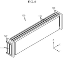
- FIG. 4 is a diagram showing the sub module 100 included in the battery module 1.
- the sub module 100 includes a plurality of battery cells 110 received in the internal receiving space of the lower housing 210 and stacked in contact with each other. Additionally, in addition of a cell stack formed by stacking the plurality of battery cells 110, the sub module 100 may further include a pair of busbar frames 120 each coupled to two sides in the lengthwise direction (X axis direction) of the cell stack.
- the battery cell 110 may include, for example, a pouch type battery cell.
- the battery cell 110 has a pair of electrode leads 111.
- the pair of electrode leads 111 may be drawn on the two sides in the lengthwise direction (X axis direction) of the battery cell 110.
- the busbar frames 120 are coupled to the cell stack and electrically connect the plurality of battery cells 110. That is, the electrode leads 111 are drawn through slits formed in the busbar frames 120 and coupled to busbars provided in the busbar frames 120. An electrical connection between adjacent battery cells 110 is established through the coupling between the electrode leads 111 and the busbars.
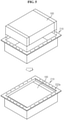
- FIG. 5 is a diagram showing a process of receiving the sub module 100 in the lower housing 210 of FIG. 3 .
- the lower housing 210 is prepared, and the sub module 100 is inserted down (in the Z axis direction) through the opening O of the lower housing 210.
- the sub module 100 is seated in the sub module receiving part 211.
- FIG. 6 is a diagram showing the first housing cover 220 included in the battery module 1.
- the first housing cover 220 is in the shape of a plate of an approximately rectangular shape on the X-Y plane, and has a gas inlet H1 formed therethrough at one of the four corner areas.
- the first housing cover 220 includes a cover receiving part 221 recessed down (Z axis direction) and a cover extended part 222 extending outward from the top periphery of the cover receiving part 221.
- the location of the gas inlet may vary depending on the intake and exhaust direction.
- the gas inlet H1 is provided at the corner area of the cover receiving part 221.
- the gas inlet H1 is preferably formed at the corner area of the cover receiving part 221, but the gas inlet may be formed at the central area of the cover receiving part 221 according to the design.
- a plurality of insertion grooves 221a for inserting/fixing the variable partition structure 400 using hinges is provided on the periphery of the inner side wall of the cover receiving part 221.
- the cover receiving part 221 has grooves 221b, 221c into which the partition structure 400 using hinges is inserted.
- the plurality of insertion grooves 221a and the plurality of grooves 221b, 221c are provided, and some of them may be used to insert/fix the variable partition structure 400 using hinges.
- the designer may implement the variable partition structure 400 using hinges to form various flame exhaust paths by selecting some of the plurality of insertion grooves 221a and the plurality of grooves 221b, 221c.
- a plurality of second coupling holes 222a formed at a predetermined interval is provided on the cover extended part 222.
- the second coupling hole 222a provides a space in which the bolt B is inserted to couple the first housing cover 220 to the lower housing 210 and the second housing cover 230.
- the first housing cover 220 may have a sealing member groove 222b formed in the cover extended part 222, and in this case, a sealing member may be inserted into the sealing member groove 222b.
- FIG. 7 is a diagram showing a process of coupling the lower housing 210 to the first housing cover 220.
- the first housing cover 220 covers the opening O of the lower housing 210 in which the sub module 100 is received and is coupled to the top of the lower housing 210. Specifically, the coupling between the first housing cover 220 and the lower housing 210 is performed in a state of contact between the cover extended part 222 of the first housing cover 220 and the housing extended part 212 of the lower housing 210.
- the first coupling hole 212a and the second coupling hole 222a are arranged at one-to-one matching locations so that they are vertically aligned, and the gas inlet H1 communicates with the sub module receiving part 211 of the lower housing 210. Accordingly, when gas and flames occur due to the venting of a certain battery cell 110 of the sub module 100 in the lower housing 210, the gas and flames enter the cover receiving part 221 of the first housing cover 220 through the gas inlet H1.
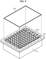
- FIG. 8 is a diagram showing a process of installing the variable partition structure 400 using hinges in the first housing cover 220.
- variable partition structure 400 using hinges is fixed and received on the first housing cover 220.
- the insertion grooves 221a and the grooves 221b, 221c described with reference to FIG. 6 are used.
- the insertion grooves 221a and the grooves 221b, 221c allow the variable partition structure 400 using hinges to be received in the cover receiving part 221 of the first housing cover 220 well without movement or separation.
- the direction of the variable partition structure 400 using hinges and/or the number of unit structures of the variable partition structure 400 using hinges may vary depending on the exhaust path. Its detailed description will be provided below.
- FIG. 9 is a diagram showing a process of installing the sealing member in the first housing cover 220.
- the first housing cover 220 may have the sealing member groove 222b formed in the cover extended part 222, and in this case, the sealing member such as the gasket 300 may be inserted into the sealing member groove 222b.
- the gasket 300 as the sealing member is inserted as shown in FIG. 9 , it is possible to enhance the sealability of the coupling interface between the first housing cover 220 and the second housing cover 230.
- FIG. 10 is a diagram showing a process of installing the second housing cover 230 on the first housing cover 220
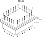
- FIG. 11 is a diagram showing a process of coupling the lower housing 210, the first housing cover 220 and the second housing cover 230.
- the second housing cover 230 is in the shape of a plate of an approximately rectangular shape on the X-Y plane and includes the gas outlet H2, and the second housing cover 230 is coupled to the first housing cover 220 from the top of the first housing cover 220.
- the location of the gas outlet may vary depending on the intake and exhaust direction, and in this embodiment, the gas outlet formed at one of the corner areas of the second housing cover 230 is taken as an example.
- the distance between the gas outlet H2 and the gas inlet H1 is preferably as long on the X-Y plane as possible.
- the gas outlet H2 may be formed at other corner area of the second housing cover 230.
- the gas outlet H2 may be formed at the central area of the second housing cover 230 according to the design.
- a plurality of third coupling holes 232a formed at a predetermined interval is provided in the second housing cover 230.
- the third coupling hole 232a provides a space in which the bolt B is inserted to couple the first housing cover 220 to the lower housing 210 and the second housing cover 230.
- the first coupling hole 212a of the housing extended part 212, the second coupling hole 222a of the cover extended part 222 and the third coupling hole 232a of the second housing cover 230 are vertically aligned.
- the cover extended part 222 of the first housing cover 220 is placed on the housing extended part 212 and the second housing cover 230 comes into contact with the cover extended part 222 of the first housing cover 220, and as shown in FIG. 11 , the first coupling hole 212a, the second coupling hole 222a and the third coupling hole 232a placed in alignment are coupled together by inserting a nut N into the bolt B passing through them.
- the second housing cover 230 may have the same shape and structure as the first housing cover 220.
- the first housing cover 220 and the second housing cover 230 are coupled upside down. That is, when the first housing cover 220 and the second housing cover 230 are coupled to each other, the cover receiving part 221 of the first housing cover 220 is recessed down, and the receiving part 221 of the second housing cover 230 is recessed up.
- the gas outlet H2 of the second housing cover 230 is disposed opposite the gas inlet H1 of the first housing cover 220 along the widthwise direction (Y axis direction) of the battery module 1.
- the first housing cover 220 and the second housing cover 230 may be in 180° rotation symmetry, and accordingly, the cover receiving parts 221 may be coupled to each other with the cover extended parts 222 in contact with each other.
- a space for receiving gas and flames entering through the gas inlet H1 from the lower housing 210 is provided between the first housing cover 220 and the second housing cover 230.
- the gas and flames entering the space passes through the exhaust path P formed by the variable partition structure 400 using hinges as described below, and in this process, the flame ceases to exist and the gas exits the battery module 1 through the gas outlet H2, and the internal pressure of the battery module 1 may reduce.
- variable partition structure 400 using hinges will be described in more detail with reference to FIGS. 12 to 17 in addition to FIGS. 2 and 8 .
- variable partition structure 400 using hinges is installed in a gas receiving space formed between the first housing cover 220 and the second housing cover 230 and partitions the gas receiving space to define the gas exhaust path P.
- the variable partition structure 400 using hinges increases the movement path of flames that occur in the sub module 100 and enter the gas receiving space through the gas inlet H1 together with gas.
- the variable partition structure 400 using hinges is provided to allow the flames to move in a zigzag or spiral shape to prevent the flames from directly moving out through the gas outlet H2, the flames may not be let out and may cease to exist in the gas receiving space.
- variable partition structure 400 using hinges may be installed across the cover receiving part 221 along the lengthwise direction (X axis direction) and/or the widthwise direction (Y axis direction) of the first housing cover 220.
- a plurality of variable partition structures 400 using hinges installed across the cover receiving part 221 along the lengthwise direction (X axis direction) of the first housing cover 220 is taken as an example.
- the plurality of variable partition structures 400 using hinges may be installed at a predetermined interval along the widthwise direction (Y axis direction) of the first housing cover 220 and the second housing cover 230.
- the variable partition structures 400 using hinges are shorter than the length of the cover receiving part 221, and some of them have one end of the lengthwise direction inserted into the left insertion groove 221a and fixed into the cover receiving part 221 and the others have the other end of the lengthwise direction inserted into the right insertion groove 221a and fixed into the cover receiving part 221.
- variable partition structure 400 using hinges having one end of the lengthwise direction inserted into the left insertion groove 221a and the variable partition structure 400 using hinges having the other end of the lengthwise direction inserted into the right insertion groove 221a are installed in an alternating manner at a predetermined interval along the widthwise direction (Y axis direction) of the first housing cover 220 and the second housing cover 230 and partitions the gas receiving space between the first housing cover 220 and the second housing cover 230 to allow gas to move in a zigzag manner.
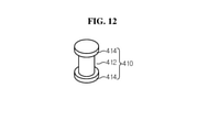
- variable partition structure 400 using hinges includes at least one hinge structure 410 and at least two partition structures 420.
- the hinge structure 410 includes a hinge axis 412 that may be placed in the Z axis direction and a hinge cap 414 that is inserted and fixed to two ends of the hinge axis 412.
- the two partition structures 420 are coupled rotatably around the hinge axis 412. It is hinge coupling.
- the hinge axis 412 is in the shape of a cylindrical rod so that the two partition structures 420 can rotate around the hinge axis 412.
- the partition structure 420 includes a body 422 in the shape of a small plate, and a first handle structure 424 at one end of the body 422 and a second handle structure 426 at the other end.
- the first handle structure 424 has a groove through which the hinge axis 412 vertically passes
- the second handle structure 426 has two grooves through which the hinge axis 412 vertically passes.
- the groove through which the hinge axis 412 vertically passes has a circular shape having the inner diameter that is similar to the outer diameter of the cylindrical rod shaped hinge axis 412.
- the first handle structure 424 and the second handle structure 426 have a circular periphery defining the circular groove.
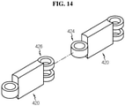
- FIGS. 14 to 16 are diagrams showing a process of assembling one hinge structure and two partition structures into a unit structure.
- the second handle structure 426 of any one partition structure 420 and the first handle structure 424 of the other partition structure 420 are put together. Accordingly, the grooves through which the hinge axis 412 passes are vertically aligned. Subsequently, the partition structures 420 are assembled by inserting the hinge axis 412 into the grooves. Subsequently, when the hinge caps 414 are inserted and fixed to the two ends of the hinge axis 412, a stable unit structure is formed without the hinge axis 412 slipping out of the grooves. The two partition structures 420 can rotate around the hinge axis 412 without slipping out of the hinge axis 412 in the presence of the hinge caps 414.
- the unit structure defining the exhaust path is formed using only three components (one hinge structure 410 and two partition structures 420), it is very easy to assemble and standardization and simplification are achieved.
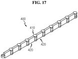
- variable partition structures 400 using hinges may be provided a little shorter than the length of the cover receiving part 221 as shown in FIG. 17 .
- variable partition structure 400 using hinges used in the present disclosure may be formed by standardizing the hinge structure 410 and the partition structure 420 and assembling desired number of hinge structures 410 and partition structures 420. It is possible to adjust the length of the variable partition structures 400 using hinges by increasing and decreasing the number of hinge structures 410 and partition structures 420. Additionally, since the partition structure 420 can rotate to the left and right around the hinge axis 412, it is possible to arrange the partition structures 420 in the horizontal or vertical direction as desired. Accordingly, it is possible to freely adjust the movement paths of gas and flames occurred in the battery module, thereby easily adjusting the length of the exhaust paths of gas and flames by a simple task without needing to replace the module housing even if there are changes in the applied voltage and capacity of the battery cell. It is possible to achieve scalability depending on the type of the battery module and make mass production easy.
- FIG. 18 is a diagram showing the gas movement path P in the battery module 1.
- the first handle structure 424 or the second handle structure 426 of the partition structure 420 is inserted or fixed to the insertion groove 212a formed in the first housing cover 220.
- the insertion groove 212a has a circular groove shape to conform to the shape of the periphery of the first handle structure 424 or the second handle structure 426, and the body 422 of the partition structure 420 runs from the side toward the cover receiving part 221.
- the first handle structure 424 or the second handle structure 426 of the partition structure 420 When the first handle structure 424 or the second handle structure 426 of the partition structure 420 is inserted into the insertion groove 212a in the downward direction (i.e., in the Z axis direction), the first handle structure 424 or the second handle structure 426 of the partition structure 420 cannot slip out of the side of the insertion groove 212a and is fixed in place.
- the cover receiving part 221 of the first housing cover 220 has the grooves 221b in horizontal and vertical grid shapes and the grooves 221c at the intersections of the grid shapes.
- the partition structure 420 is received in the groove 221b, and the hinge structure 410 is received in the groove 221c.
- the groove 221c that receives the hinge structure 410 is a groove of a circular shape to conform to the X-Y plane projected shape of the hinge cap 414 of the hinge structure 410.
- the groove 221b that receives the partition structure 420 is a groove of a rectangular shape to conform to the X-Y plane projected shape of the body 422 of the partition structure 420. In case that the hinge cap 414 and the body 422 of the partition structure 420 have different X-Y plane projected shapes, the shape of the groove 221b that receives the partition structure 420 and the groove 221c that receives the hinge structure 410 may change accordingly.
- the cover receiving part 221 has the plurality of insertion grooves 221a for inserting/fixing the variable partition structures 400 using hinges on the periphery of the inner side wall thereof. Additionally, the cover receiving part 221 has the grooves 221b, 221c into which the partition structures 420 using hinges are inserted.
- the plurality of insertion grooves 221a and the plurality of grooves 221b, 221c may be provided, and only some of them may be used to insert/fix the variable partition structures 400 using hinges.
- the designer may implement the variable partition structure 400 using hinges to form various flame exhaust paths by selecting some of the plurality of insertion grooves 221a and the plurality of grooves 221b, 221c.
- the partition structures 420 are inserted into some of the grooves 221b and are not inserted into the others. The flames are blocked by the partition structures 420 and pass through the grooves into which the partition structures 420 are not inserted.
- the sparsely arranged variable partition structures 400 using hinges are taken as an example, so that the flame entering together with gas that occurs in the sub module 100 and enters the gas receiving space through the gas inlet H1 of the first housing cover 220 does not directly exit through the gas outlet H2 of the second housing cover 230, and allow flames to move a long distance in a zigzag shape within the gas receiving space.
- the flames entering with the gas are arrested in the exhaust path P to prevent the flames from moving out. Only gas is forced out through the gas outlet H2, thereby ensuring safety.
- the battery module 1 may effectively prevent flames from moving out while smoothly expelling gas occurred in the sub module 100 by changing the number and array of variable partition structures 400 using hinges as necessary.
- the partition structure 420 also plays a role of a stiff structure as a bead, and an appropriate number may be selected in the trade off relationship between stiffness suppression and material cost. For example, in the case of FIG. 18 , due to the large explosion, a large number of variable partition structures 400 using hinges (for example, 7) is used to increase the strength though the material cost is high.
- the number of variable partition structures 400 using hinges is smaller than that of FIG. 18 (for example, 3).
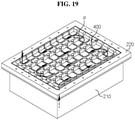
- the number of variable partition structures 400 using hinges needed may reduce, thereby reducing the material cost. Accordingly, it is possible to reduce the cost by using a small number of variable partition structures 400 using hinges as shown in FIG. 19 .
- explosion is moderate, it is possible to achieve a proper material cost and strength by using an intermediate number of variable partition structures 400 using hinges between FIGS. 18 and 19 .
- FIGS. 18 and 19 show that the exhaust path P directs flames toward one of the corner areas of the second housing cover, i.e., one edge, and as shown in FIG. 20 , the exhaust path P' may direct flames toward the center of the second housing cover.
- the number of variable partition structures 400 using hinges is 1, the partition structure 420 changes the direction by 90° bend in the left counterclockwise direction at each corner area. In this instance, the gas outlet is provided at the center of the second housing cover 230.
- the variable partition structure 400 using hinges according to the present disclosure can change the direction of the partition structure 420 with respect to the hinge axis 412, so it is very useful for directing flames in a desired direction.
- a battery pack according to the present disclosure includes at least one battery module according to the present disclosure as described above.
- FIG. 21 is a schematic diagram showing the battery pack 500 according to an embodiment of the present disclosure.
- the battery pack 500 may include at least one battery module 1 according to the previous embodiment and a pack case 510 to package the at least one battery module 1.
- the battery pack 500 according to an embodiment of the present disclosure may further include various types of devices for controlling the charge/discharge of the battery module 1, for example, a Battery Management System (BMS), a current sensor and a fuse. Since the battery pack 500 includes the battery module 1, the battery pack 500 may be used as a battery pack having the feature and effect of the battery module 1.
- BMS Battery Management System
- the battery pack 500 may be used as a battery pack having the feature and effect of the battery module 1.
- a vehicle and/or an energy storage system (ESS) includes at least one battery pack of the present disclosure as described above.
- FIG. 22 is a schematic diagram showing the vehicle 600 including the battery pack 500 according to an embodiment of the present disclosure.
- the vehicle 600 may include the battery pack 500 according to an embodiment of the present disclosure, an Electronic Control Unit (ECU) 610, an inverter 620 and a motor 630.
- ECU Electronic Control Unit
- the vehicle 600 may be an electric vehicle.
- the battery pack 500 may be used as an electrical energy source that supplies power to the motor 630 to drive the vehicle 600.
- the battery pack 500 may be charged or discharged by the inverter 620 by the operation of the motor 630 and/or an internal combustion engine (not shown).
- the battery pack 500 may be charged by a regenerative charging system coupled to a brake.
- the battery pack 500 may be electrically connected to the motor 630 of the vehicle 600 through the inverter 620.
- the battery pack 500 includes the BMS.
- the BMS estimates the condition of the cells in the battery pack 500, and manages the battery pack 500 using the estimated condition information.
- the BMS estimates and manages the condition information of the battery pack 500 such as State Of Charge (SOC), State Of Health (SOH), maximum allowable input/output power capacity and output voltage of the battery pack 500.
- the condition information may be used to control the charge or discharge of the battery pack 500, and further, to predict when to replace the battery pack 500.
- the ECU 610 is an electronic control device that controls the condition of the vehicle 600. For example, the ECU 610 determines torque information based on accelerator, brake and speed information, and controls the output of the motor 630 according to the torque information. Additionally, the ECU 610 transmits a control signal to the inverter 620 to charge or discharge the battery pack 500 based on the condition information such as the SOC and SOH of the battery pack 500 received from the BMS. The inverter 620 allows the battery pack 500 to be charged or discharged based on the control signal of the ECU 610. The motor 630 drives the vehicle 600 based on the control information (for example, torque information) received from the ECU 610 using the electrical energy of the battery pack 500.
- the control information for example, torque information
- the vehicle 600 includes the battery pack 500, and the battery pack 500 includes the battery module 1 as described above and thus may increase the flame movement path. Accordingly, even if a problem occurs in the battery pack 500 while the vehicle 600 is driving, stability is maintained. Additionally, the battery pack 500 has high stability and can be used for a long time, and thus the vehicle 600 including the same is safety and easy to manage.
- the ESS may use the battery pack according to the present disclosure to store the power.
- the battery pack according to the present disclosure includes the battery module according to the present disclosure as described above and thus may increase the flame movement path. Accordingly, even though a failure occurs in a certain battery pack, it is possible to keep the ESS stable and prevent a fire from spreading.
Landscapes
- Chemical & Material Sciences (AREA)
- General Chemical & Material Sciences (AREA)
- Electrochemistry (AREA)
- Chemical Kinetics & Catalysis (AREA)
- Engineering & Computer Science (AREA)
- Power Engineering (AREA)
- Mechanical Engineering (AREA)
- Transportation (AREA)
- Aviation & Aerospace Engineering (AREA)
- Life Sciences & Earth Sciences (AREA)
- Sustainable Energy (AREA)
- Sustainable Development (AREA)
- Health & Medical Sciences (AREA)
- Public Health (AREA)
- Business, Economics & Management (AREA)
- Emergency Management (AREA)
- Battery Mounting, Suspending (AREA)
- Gas Exhaust Devices For Batteries (AREA)
Abstract
Description
- The present disclosure relates to a battery module having a flame arresting structure and a battery pack comprising the battery module. More particularly, the present disclosure relates to a battery module having a structure for forcing gas out of the battery module and preventing flames from moving out of the battery module when the gas and flames occur due to a failure in battery cells received in a module housing, and a battery pack comprising the battery module. Additionally, the present disclosure relates to a vehicle and an Energy Storage System (ESS) comprising the battery pack. The present application claims the benefit of
Korean Patent Application No. 10-2020-0046950 filed on April 17, 2020 - A battery pack used for Energy Storage Systems (ESSs) or as an electrical energy source of vehicles is configured to properly function for the installation environment and usage condition, free of risks caused by external physical factors while in use. The battery pack for ESSs or vehicles may include at least one battery module and a Battery Management System (BMS) electrically connected to the battery module.
- The battery pack for ESSs or vehicles includes a plurality of battery cells to ensure sufficient capacity and output, and the battery pack needs to be designed to ensure a user's safety when a certain battery cell fails while in use. For example, when gas leakage and flaming occurs due to the venting of the battery cell in the battery module of the battery pack, it is necessary to force the gas out of the battery module to reduce the internal pressure of the battery module, while bringing the flames to end in the battery module. To prevent the flames occurred in the battery module from moving out through a gas vent hole formed to force the gas out, the flame movement path may be formed as long as possible to prolong the time required for the flames to move from the location at which the flames occurred to the gas vent hole.
- However, the number of battery cells received in the battery module and the capacity and voltage of each battery cell may vary depending on the purpose of use of the battery module, and accordingly, the total capacity and output voltage of the battery module may vary. Accordingly, when gas and flames occur due to a failure in the battery module, the gas and flames may occur in different scales depending on the purpose of use of the battery module, and it is necessary to differently design the length of the gas and flame movement paths to ensure safety.
- From this perspective, there is a need for the development of a module housing and a battery module having a structure for freely adjusting the movement paths of gas and flames occurred in the battery module.
- The present disclosure is designed to solve the above-described problem, and therefore the present disclosure is directed to providing a battery module having a structure for freely adjusting the movement paths of gas and flames occurring in the battery module, so that even though there are changes in applied voltage and capacity of a battery cell, it is possible to easily adjust the length of the exhaust paths of gas and flames by a simple task without needing to replace a module housing.
- The object of the present disclosure is not limited to the above-described object, and these and other objects will be clearly understood by those skilled in the art from the following detailed description.
- To solve the above-described problem, a battery module according to an embodiment of the present disclosure includes a sub module including a plurality of battery cells, a lower housing to receive the sub module therein and having an opening, a first housing cover coupled to the lower housing, covering the opening of the lower housing, and having a gas inlet, a second housing cover coupled to the first housing cover from above to form a gas receiving space therebetween, and having a gas outlet, and a variable partition structure using hinges installed in the gas receiving space to partition the gas receiving space to define a gas exhaust path to increase a movement path of a flame entering together with gas occurred in the sub module and entering the gas receiving space through the gas inlet.
- Preferably, the variable partition structure using hinges includes at least one hinge structure and at least two partition structures, the hinge structure includes a hinge axis and a hinge cap inserted and fixed to two ends of the hinge axis, and the two partition structures are coupled rotatably around the hinge axis.
- In particular, the partition structure may have a first handle structure at one end and a second handle structure at the other end, the first handle structure having a groove through which the hinge axis passes and the second handle structure having two grooves through which the hinge axis passes, the second handle structure of any one partition structure and the first handle structure of another partition structure may be assembled with each other such that the grooves are vertically aligned, and the partition structures may be connected to each other by inserting the hinge axis into the grooves.
- In a preferred embodiment, the first housing cover includes a cover receiving part recessed down, and a cover extended part extending outward from a top periphery of the cover receiving part.
- The lower housing may include a sub module receiving part for receiving the sub module and a housing extended part extending outward from a top periphery of the sub module receiving part on a periphery of the opening, and the cover extended part of the first housing cover may be placed on the housing extended part and the second housing cover may be coupled in contact with the cover extended part of the first housing cover.
- In this instance, the housing extended part of the lower housing, the cover extended part of the first housing cover and the second housing cover may have coupling holes that are vertically aligned.
- Accordingly, a nut may be coupled to a bolt passing through the coupling holes with a sealing member interposed between the first housing cover and the second housing cover.
- In a preferred embodiment, the first housing cover has a plurality of insertion grooves formed on a periphery of an inner side wall of the cover receiving part to fix the first handle structure or the second handle structure of the partition structure.
- Preferably, the first housing cover has grooves for receiving the partition structure in horizontal and vertical grid shapes in the cover receiving part, and grooves for receiving the hinge structure at intersections of the grid shapes.
- There are some of the grooves into which the partition structure is inserted and the others into which the partition structure is not inserted, and the flame is blocked by the partition structure and passes through the grooves into which the partition structure is not inserted.
- In this instance, the partition structure may be provided to move the flame in a zigzag or spiral shape.
- Preferably, the gas inlet and the gas outlet are disposed on opposite sides along a widthwise direction of the battery module.
- To solve the above-described problem, a battery pack according to an embodiment of the present disclosure includes at least one battery module according to an embodiment of the present disclosure.
- To solve the above-described problem, a vehicle according to an embodiment of the present disclosure includes at least one battery pack according to an embodiment of the present disclosure.
- To solve the above-described problem, an energy storage system according to an embodiment of the present disclosure includes at least one battery pack according to an embodiment of the present disclosure.
- According to an aspect of the present disclosure, it is possible to freely adjust the movement paths of gas and flames occurring in the battery module, thereby easily adjusting the length of the exhaust paths of gas and flames by a simple task without needing to replace the module housing even through there are changes in the applied voltage and capacity of the battery cell.
- The present disclosure designs an exhaust passage to expel the exhaust gas on the top of the battery module when thermal runaway of the battery module occurs through the variable partition structure using hinges, and prevent the flames from being exposed to the outside. Accordingly, the present disclosure provides a battery module having a flame arresting structure. When flames occurred in a sub module enter the gas receiving space through the gas inlet together with gas, it is possible to prevent the flames from moving out through the gas outlet and let the flames fade away in the gas receiving space by increasing the movement path of the flames.
- The variable partition structure using hinges used in the present disclosure can assemble a desired number of components, and uses standardized components, which makes mass production easy. Additionally, the partition structure can rotate left and right around the hinge axis, making it possible to place in a desired direction.
- The variable partition structure using hinges also plays a role of a stiff structure as a bead, and an appropriate number may be selected in the trade off relationship between stiffness suppression and material cost. That is, when explosion is small, the number of partition structures needed may reduce, thereby reducing the material cost. When explosion is large, the number of partition structures may increase to increase the strength though the material cost is high.
- The accompanying drawings illustrate the preferred embodiments of the present disclosure, and together with the detailed description of the present disclosure described below, serve to provide a further understanding of the technical aspects of the present disclosure, and thus the present disclosure should not be construed as being limited to the drawings.
-
FIG. 1 is a perspective view of a battery module according to an embodiment of the present disclosure. -
FIG. 2 is a diagram showing the battery module ofFIG. 1 from which a second housing cover is removed. -
FIG. 3 is a diagram showing a lower housing included in the battery module ofFIG. 1 . -
FIG. 4 is a diagram showing a sub module included in the battery module ofFIG. 1 . -
FIG. 5 is a diagram showing a process of receiving a sub module in the lower housing ofFIG. 3 . -
FIG. 6 is a diagram showing a first housing cover included in the battery module ofFIG. 1 . -
FIG. 7 is a diagram showing a process of coupling a lower housing to a first housing cover included in the battery module ofFIG. 1 . -
FIG. 8 is a diagram showing a process of installing a variable partition structure using hinges in a first housing cover included in the battery module ofFIG. 1 . -
FIG. 9 is a diagram showing a process of installing a sealing member in a first housing cover included in the battery module ofFIG. 1 . -
FIG. 10 is a diagram showing a process of installing a second housing cover on a first housing cover included in the battery module ofFIG. 1 . -
FIG. 11 is a diagram showing a process of coupling a lower housing, a first housing cover and a second housing cover included in the battery module ofFIG. 1 . -
FIG. 12 is a diagram showing a hinge structure included in the battery module ofFIG. 1 . -
FIG. 13 is a diagram showing a partition structure included in the battery module ofFIG. 1 . -
FIGS. 14 to 16 are diagrams showing a process of assembling one hinge structure and two partition structures into a unit structure. -
FIG. 17 is a diagram showing a variable partition structure using hinges included in the battery module ofFIG. 1 . -
FIG. 18 is a diagram showing a gas movement path in the battery module ofFIG. 1 . -
FIGS. 19 and20 are diagrams showing a gas movement path in a battery module according to another embodiment of the present disclosure. -
FIG. 21 is a schematic diagram showing a battery pack according to another embodiment of the present disclosure. -
FIG. 22 is a schematic diagram showing a vehicle including a battery pack according to still another embodiment of the present disclosure. - Hereinafter, the preferred embodiments of the present disclosure will be described in detail with reference to the accompanying drawings. Prior to the description, it should be understood that the terms or words used in the specification and the appended claims should not be construed as being limited to general and dictionary meanings, but rather interpreted based on the meanings and concepts corresponding to the technical aspects of the present disclosure on the basis of the principle that the inventor is allowed to define the terms appropriately for the best explanation. Therefore, the embodiments described herein and illustrations shown in the drawings are just a most preferred embodiment of the present disclosure, but not intended to fully describe the technical aspects of the present disclosure, so it should be understood that a variety of other equivalents and modifications could have been made thereto at the time that the application was filed.
- First, a schematic structure of a battery module according to an embodiment of the present disclosure will be described with reference to
FIGS. 1 and2 .FIG. 1 is a perspective view of thebattery module 1 according to an embodiment of the present disclosure.FIG. 2 is a diagram showing thebattery module 1 ofFIG. 1 from which asecond housing cover 230 is removed. - Referring to
FIGS. 1 and2 , thebattery module 1 according to an embodiment of the present disclosure includes amodule housing 200. Themodule housing 200 includes a sub module (not shown) and avariable partition structure 400 using hinges. Additionally, thebattery module 1 may further include agasket 300 to ensure sealability. - The
module housing 200 includes alower housing 210, afirst housing cover 220 and asecond housing cover 230. Thelower housing 210, thefirst housing cover 220 and thesecond housing cover 230 are coupled with a bolt B. Themodule housing 200 may receive a cell or the sub module therein. Thefirst housing cover 220 and thesecond housing cover 230 are placed on top in the Z axis direction of thelower housing 210, and coupled to form a flame arresting structure. In this instance, thefirst housing cover 220 forms an exhaust path lower plate, and thesecond housing cover 230 forms an exhaust path upper plate. - The
variable partition structure 400 using hinges is fixed and received on thefirst housing cover 220 and forms a flame exhaust path P between thefirst housing cover 220 and thesecond housing cover 230. - By the
battery module 1, it is possible to capture flames between thefirst housing cover 220 and thesecond housing cover 230 when a fire occurs in the sub module. Thebattery module 1 may force gas out of thebattery module 1 through an outlet H2 of thesecond housing cover 230, and arrest flames in thebattery module 1 or bring flames to end. - It is possible to freely adjust the length and direction of the
variable partition structure 400 using hinges. Accordingly, it is possible to conform to different battery module sizes. Thevariable partition structure 400 using hinges can freely adjust the movement paths of gas and flames occurring in thebattery module 1. It is possible to easily adjust the length of the exhaust paths of gas and flames by a task of changing thevariable partition structure 400 using hinges without needing to replace themodule housing 200 even though there are changes in the applied voltage and capacity of the battery cell. - Hereinafter, the detailed structure and manufacturing method of the
battery module 1 will be described in detail with reference toFIGS. 3 to 11 together withFIGS. 1 and2 . -
FIG. 3 is a diagram showing thelower housing 210 included in thebattery module 1 shown inFIG. 1 . - Referring to
FIG. 3 , thelower housing 210 corresponds to a top open bottom plate. Thelower housing 210 has an opening O on top in the Z axis direction, and may receive the sub module in a receiving space formed at the center. Thelower housing 210 includes a submodule receiving part 211 recessed down (Z axis direction) at the center and a housingextended part 212 extending outward from the top periphery of the submodule receiving part 211 on the periphery of the opening O. The sub module is received in the submodule receiving part 211. The housing extendedpart 212 has a plurality offirst coupling holes 212a thereon at a predetermined interval. Thefirst coupling hole 212a provides a space into which the bolt B is inserted to couple thelower housing 210 to thefirst housing cover 220 and thesecond housing cover 230. -
FIG. 4 is a diagram showing thesub module 100 included in thebattery module 1. - Referring to
FIG. 4 , thesub module 100 includes a plurality ofbattery cells 110 received in the internal receiving space of thelower housing 210 and stacked in contact with each other. Additionally, in addition of a cell stack formed by stacking the plurality ofbattery cells 110, thesub module 100 may further include a pair of busbar frames 120 each coupled to two sides in the lengthwise direction (X axis direction) of the cell stack. - The
battery cell 110 may include, for example, a pouch type battery cell. Thebattery cell 110 has a pair of electrode leads 111. The pair of electrode leads 111 may be drawn on the two sides in the lengthwise direction (X axis direction) of thebattery cell 110. - The busbar frames 120 are coupled to the cell stack and electrically connect the plurality of
battery cells 110. That is, the electrode leads 111 are drawn through slits formed in the busbar frames 120 and coupled to busbars provided in the busbar frames 120. An electrical connection betweenadjacent battery cells 110 is established through the coupling between the electrode leads 111 and the busbars. -
FIG. 5 is a diagram showing a process of receiving thesub module 100 in thelower housing 210 ofFIG. 3 . - Referring to
FIG. 5 , to assemble thebattery module 1, first, thelower housing 210 is prepared, and thesub module 100 is inserted down (in the Z axis direction) through the opening O of thelower housing 210. Thesub module 100 is seated in the submodule receiving part 211. -
FIG. 6 is a diagram showing thefirst housing cover 220 included in thebattery module 1. - Referring to
FIG. 6 , thefirst housing cover 220 is in the shape of a plate of an approximately rectangular shape on the X-Y plane, and has a gas inlet H1 formed therethrough at one of the four corner areas. Thefirst housing cover 220 includes acover receiving part 221 recessed down (Z axis direction) and a coverextended part 222 extending outward from the top periphery of thecover receiving part 221. The location of the gas inlet may vary depending on the intake and exhaust direction. In this embodiment, the gas inlet H1 is provided at the corner area of thecover receiving part 221. To ensure a sufficient length of the flame exhaust path, the gas inlet H1 is preferably formed at the corner area of thecover receiving part 221, but the gas inlet may be formed at the central area of thecover receiving part 221 according to the design. - A plurality of
insertion grooves 221a for inserting/fixing thevariable partition structure 400 using hinges is provided on the periphery of the inner side wall of thecover receiving part 221. Thecover receiving part 221 hasgrooves partition structure 400 using hinges is inserted. The plurality ofinsertion grooves 221a and the plurality ofgrooves variable partition structure 400 using hinges. The designer may implement thevariable partition structure 400 using hinges to form various flame exhaust paths by selecting some of the plurality ofinsertion grooves 221a and the plurality ofgrooves - A plurality of
second coupling holes 222a formed at a predetermined interval is provided on the cover extendedpart 222. Thesecond coupling hole 222a provides a space in which the bolt B is inserted to couple thefirst housing cover 220 to thelower housing 210 and thesecond housing cover 230. - The
first housing cover 220 may have a sealingmember groove 222b formed in the cover extendedpart 222, and in this case, a sealing member may be inserted into the sealingmember groove 222b. -
FIG. 7 is a diagram showing a process of coupling thelower housing 210 to thefirst housing cover 220. - Referring to
FIG. 7 , thefirst housing cover 220 covers the opening O of thelower housing 210 in which thesub module 100 is received and is coupled to the top of thelower housing 210. Specifically, the coupling between thefirst housing cover 220 and thelower housing 210 is performed in a state of contact between the cover extendedpart 222 of thefirst housing cover 220 and the housing extendedpart 212 of thelower housing 210. When thefirst housing cover 220 is coupled to thelower housing 210, thefirst coupling hole 212a and thesecond coupling hole 222a are arranged at one-to-one matching locations so that they are vertically aligned, and the gas inlet H1 communicates with the submodule receiving part 211 of thelower housing 210. Accordingly, when gas and flames occur due to the venting of acertain battery cell 110 of thesub module 100 in thelower housing 210, the gas and flames enter thecover receiving part 221 of thefirst housing cover 220 through the gas inlet H1. -
FIG. 8 is a diagram showing a process of installing thevariable partition structure 400 using hinges in thefirst housing cover 220. - Referring to
FIG. 8 , thevariable partition structure 400 using hinges is fixed and received on thefirst housing cover 220. In this instance, theinsertion grooves 221a and thegrooves FIG. 6 are used. Theinsertion grooves 221a and thegrooves variable partition structure 400 using hinges to be received in thecover receiving part 221 of thefirst housing cover 220 well without movement or separation. The direction of thevariable partition structure 400 using hinges and/or the number of unit structures of thevariable partition structure 400 using hinges may vary depending on the exhaust path. Its detailed description will be provided below. -
FIG. 9 is a diagram showing a process of installing the sealing member in thefirst housing cover 220. - As described with reference to
FIG. 6 , thefirst housing cover 220 may have the sealingmember groove 222b formed in the cover extendedpart 222, and in this case, the sealing member such as thegasket 300 may be inserted into the sealingmember groove 222b. When thegasket 300 as the sealing member is inserted as shown inFIG. 9 , it is possible to enhance the sealability of the coupling interface between thefirst housing cover 220 and thesecond housing cover 230. -
FIG. 10 is a diagram showing a process of installing thesecond housing cover 230 on thefirst housing cover 220, andFIG. 11 is a diagram showing a process of coupling thelower housing 210, thefirst housing cover 220 and thesecond housing cover 230. - Referring to
FIG. 10 , thesecond housing cover 230 is in the shape of a plate of an approximately rectangular shape on the X-Y plane and includes the gas outlet H2, and thesecond housing cover 230 is coupled to thefirst housing cover 220 from the top of thefirst housing cover 220. In the same way as the gas inlet, the location of the gas outlet may vary depending on the intake and exhaust direction, and in this embodiment, the gas outlet formed at one of the corner areas of thesecond housing cover 230 is taken as an example. To ensure a sufficient length of the flame exhaust path, the distance between the gas outlet H2 and the gas inlet H1 is preferably as long on the X-Y plane as possible. Since the gas inlet H1 formed at any one corner area of thecover receiving part 221 is taken as an example, the gas outlet H2 may be formed at other corner area of thesecond housing cover 230. The gas outlet H2 may be formed at the central area of thesecond housing cover 230 according to the design. - A plurality of
third coupling holes 232a formed at a predetermined interval is provided in thesecond housing cover 230. Thethird coupling hole 232a provides a space in which the bolt B is inserted to couple thefirst housing cover 220 to thelower housing 210 and thesecond housing cover 230. - In this instance, the
first coupling hole 212a of the housing extendedpart 212, thesecond coupling hole 222a of the cover extendedpart 222 and thethird coupling hole 232a of thesecond housing cover 230 are vertically aligned. The cover extendedpart 222 of thefirst housing cover 220 is placed on the housing extendedpart 212 and thesecond housing cover 230 comes into contact with the cover extendedpart 222 of thefirst housing cover 220, and as shown inFIG. 11 , thefirst coupling hole 212a, thesecond coupling hole 222a and thethird coupling hole 232a placed in alignment are coupled together by inserting a nut N into the bolt B passing through them. - Meanwhile, the
second housing cover 230 may have the same shape and structure as thefirst housing cover 220. In this instance, thefirst housing cover 220 and thesecond housing cover 230 are coupled upside down. That is, when thefirst housing cover 220 and thesecond housing cover 230 are coupled to each other, thecover receiving part 221 of thefirst housing cover 220 is recessed down, and the receivingpart 221 of thesecond housing cover 230 is recessed up. Additionally, the gas outlet H2 of thesecond housing cover 230 is disposed opposite the gas inlet H1 of thefirst housing cover 220 along the widthwise direction (Y axis direction) of thebattery module 1. As described above, thefirst housing cover 220 and thesecond housing cover 230 may be in 180° rotation symmetry, and accordingly, thecover receiving parts 221 may be coupled to each other with the cover extendedparts 222 in contact with each other. - In any cases, when the
first housing cover 220 and thesecond housing cover 230 are coupled, a space for receiving gas and flames entering through the gas inlet H1 from thelower housing 210 is provided between thefirst housing cover 220 and thesecond housing cover 230. The gas and flames entering the space passes through the exhaust path P formed by thevariable partition structure 400 using hinges as described below, and in this process, the flame ceases to exist and the gas exits thebattery module 1 through the gas outlet H2, and the internal pressure of thebattery module 1 may reduce. - The
variable partition structure 400 using hinges will be described in more detail with reference toFIGS. 12 to 17 in addition toFIGS. 2 and8 . - As shown in
FIGS. 2 and8 , thevariable partition structure 400 using hinges is installed in a gas receiving space formed between thefirst housing cover 220 and thesecond housing cover 230 and partitions the gas receiving space to define the gas exhaust path P. Thevariable partition structure 400 using hinges increases the movement path of flames that occur in thesub module 100 and enter the gas receiving space through the gas inlet H1 together with gas. When thevariable partition structure 400 using hinges is provided to allow the flames to move in a zigzag or spiral shape to prevent the flames from directly moving out through the gas outlet H2, the flames may not be let out and may cease to exist in the gas receiving space. Thevariable partition structure 400 using hinges may be installed across thecover receiving part 221 along the lengthwise direction (X axis direction) and/or the widthwise direction (Y axis direction) of thefirst housing cover 220. In this embodiment, a plurality ofvariable partition structures 400 using hinges installed across thecover receiving part 221 along the lengthwise direction (X axis direction) of thefirst housing cover 220 is taken as an example. - The plurality of
variable partition structures 400 using hinges may be installed at a predetermined interval along the widthwise direction (Y axis direction) of thefirst housing cover 220 and thesecond housing cover 230. In this embodiment, thevariable partition structures 400 using hinges are shorter than the length of thecover receiving part 221, and some of them have one end of the lengthwise direction inserted into theleft insertion groove 221a and fixed into thecover receiving part 221 and the others have the other end of the lengthwise direction inserted into theright insertion groove 221a and fixed into thecover receiving part 221. - The
variable partition structure 400 using hinges having one end of the lengthwise direction inserted into theleft insertion groove 221a and thevariable partition structure 400 using hinges having the other end of the lengthwise direction inserted into theright insertion groove 221a are installed in an alternating manner at a predetermined interval along the widthwise direction (Y axis direction) of thefirst housing cover 220 and thesecond housing cover 230 and partitions the gas receiving space between thefirst housing cover 220 and thesecond housing cover 230 to allow gas to move in a zigzag manner. - Referring to
FIGS. 12 to 17 , thevariable partition structure 400 using hinges includes at least onehinge structure 410 and at least twopartition structures 420. - As shown in
FIG. 12 , thehinge structure 410 includes ahinge axis 412 that may be placed in the Z axis direction and ahinge cap 414 that is inserted and fixed to two ends of thehinge axis 412. The twopartition structures 420 are coupled rotatably around thehinge axis 412. It is hinge coupling. Thehinge axis 412 is in the shape of a cylindrical rod so that the twopartition structures 420 can rotate around thehinge axis 412. - Referring to
FIG. 13 , thepartition structure 420 includes abody 422 in the shape of a small plate, and afirst handle structure 424 at one end of thebody 422 and asecond handle structure 426 at the other end. Thefirst handle structure 424 has a groove through which thehinge axis 412 vertically passes, and thesecond handle structure 426 has two grooves through which thehinge axis 412 vertically passes. The groove through which thehinge axis 412 vertically passes has a circular shape having the inner diameter that is similar to the outer diameter of the cylindrical rod shapedhinge axis 412. Thefirst handle structure 424 and thesecond handle structure 426 have a circular periphery defining the circular groove. -
FIGS. 14 to 16 are diagrams showing a process of assembling one hinge structure and two partition structures into a unit structure. - First, as shown in
FIG. 14 , thesecond handle structure 426 of any onepartition structure 420 and thefirst handle structure 424 of theother partition structure 420 are put together. Accordingly, the grooves through which thehinge axis 412 passes are vertically aligned. Subsequently, thepartition structures 420 are assembled by inserting thehinge axis 412 into the grooves. Subsequently, when the hinge caps 414 are inserted and fixed to the two ends of thehinge axis 412, a stable unit structure is formed without thehinge axis 412 slipping out of the grooves. The twopartition structures 420 can rotate around thehinge axis 412 without slipping out of thehinge axis 412 in the presence of the hinge caps 414. - Since the unit structure defining the exhaust path is formed using only three components (one
hinge structure 410 and two partition structures 420), it is very easy to assemble and standardization and simplification are achieved. - A necessary number of unit structures may be additionally connected by repeating the above-described process a desired number of times. For example, the
variable partition structures 400 using hinges may be provided a little shorter than the length of thecover receiving part 221 as shown inFIG. 17 . - The
variable partition structure 400 using hinges used in the present disclosure may be formed by standardizing thehinge structure 410 and thepartition structure 420 and assembling desired number ofhinge structures 410 andpartition structures 420. It is possible to adjust the length of thevariable partition structures 400 using hinges by increasing and decreasing the number ofhinge structures 410 andpartition structures 420. Additionally, since thepartition structure 420 can rotate to the left and right around thehinge axis 412, it is possible to arrange thepartition structures 420 in the horizontal or vertical direction as desired. Accordingly, it is possible to freely adjust the movement paths of gas and flames occurred in the battery module, thereby easily adjusting the length of the exhaust paths of gas and flames by a simple task without needing to replace the module housing even if there are changes in the applied voltage and capacity of the battery cell. It is possible to achieve scalability depending on the type of the battery module and make mass production easy. -
FIG. 18 is a diagram showing the gas movement path P in thebattery module 1. - Referring to
FIG. 18 , thefirst handle structure 424 or thesecond handle structure 426 of thepartition structure 420 is inserted or fixed to theinsertion groove 212a formed in thefirst housing cover 220. Theinsertion groove 212a has a circular groove shape to conform to the shape of the periphery of thefirst handle structure 424 or thesecond handle structure 426, and thebody 422 of thepartition structure 420 runs from the side toward thecover receiving part 221. When thefirst handle structure 424 or thesecond handle structure 426 of thepartition structure 420 is inserted into theinsertion groove 212a in the downward direction (i.e., in the Z axis direction), thefirst handle structure 424 or thesecond handle structure 426 of thepartition structure 420 cannot slip out of the side of theinsertion groove 212a and is fixed in place. - The
cover receiving part 221 of thefirst housing cover 220 has thegrooves 221b in horizontal and vertical grid shapes and thegrooves 221c at the intersections of the grid shapes. Thepartition structure 420 is received in thegroove 221b, and thehinge structure 410 is received in thegroove 221c. Thegroove 221c that receives thehinge structure 410 is a groove of a circular shape to conform to the X-Y plane projected shape of thehinge cap 414 of thehinge structure 410. Thegroove 221b that receives thepartition structure 420 is a groove of a rectangular shape to conform to the X-Y plane projected shape of thebody 422 of thepartition structure 420. In case that thehinge cap 414 and thebody 422 of thepartition structure 420 have different X-Y plane projected shapes, the shape of thegroove 221b that receives thepartition structure 420 and thegroove 221c that receives thehinge structure 410 may change accordingly. - As described above, the
cover receiving part 221 has the plurality ofinsertion grooves 221a for inserting/fixing thevariable partition structures 400 using hinges on the periphery of the inner side wall thereof. Additionally, thecover receiving part 221 has thegrooves partition structures 420 using hinges are inserted. The plurality ofinsertion grooves 221a and the plurality ofgrooves variable partition structures 400 using hinges. The designer may implement thevariable partition structure 400 using hinges to form various flame exhaust paths by selecting some of the plurality ofinsertion grooves 221a and the plurality ofgrooves - The
partition structures 420 are inserted into some of thegrooves 221b and are not inserted into the others. The flames are blocked by thepartition structures 420 and pass through the grooves into which thepartition structures 420 are not inserted. - There are some of the
grooves 221b into which thepartition structures 420 are not inserted, and theopen grooves 221b form the exhaust path P along which gas and flames move. In this embodiment, the sparsely arrangedvariable partition structures 400 using hinges are taken as an example, so that the flame entering together with gas that occurs in thesub module 100 and enters the gas receiving space through the gas inlet H1 of thefirst housing cover 220 does not directly exit through the gas outlet H2 of thesecond housing cover 230, and allow flames to move a long distance in a zigzag shape within the gas receiving space. The flames entering with the gas are arrested in the exhaust path P to prevent the flames from moving out. Only gas is forced out through the gas outlet H2, thereby ensuring safety. - Meanwhile, referring to
FIGS. 19 and20 , thebattery module 1 according to an embodiment of the present disclosure may effectively prevent flames from moving out while smoothly expelling gas occurred in thesub module 100 by changing the number and array ofvariable partition structures 400 using hinges as necessary. - The
partition structure 420 also plays a role of a stiff structure as a bead, and an appropriate number may be selected in the trade off relationship between stiffness suppression and material cost. For example, in the case ofFIG. 18 , due to the large explosion, a large number ofvariable partition structures 400 using hinges (for example, 7) is used to increase the strength though the material cost is high. - In
FIG. 19 , the number ofvariable partition structures 400 using hinges is smaller than that ofFIG. 18 (for example, 3). When explosion is small, the number ofvariable partition structures 400 using hinges needed may reduce, thereby reducing the material cost. Accordingly, it is possible to reduce the cost by using a small number ofvariable partition structures 400 using hinges as shown inFIG. 19 . When explosion is moderate, it is possible to achieve a proper material cost and strength by using an intermediate number ofvariable partition structures 400 using hinges betweenFIGS. 18 and19 . - Meanwhile,
FIGS. 18 and19 show that the exhaust path P directs flames toward one of the corner areas of the second housing cover, i.e., one edge, and as shown inFIG. 20 , the exhaust path P' may direct flames toward the center of the second housing cover. Although the number ofvariable partition structures 400 using hinges is 1, thepartition structure 420 changes the direction by 90° bend in the left counterclockwise direction at each corner area. In this instance, the gas outlet is provided at the center of thesecond housing cover 230. Thevariable partition structure 400 using hinges according to the present disclosure can change the direction of thepartition structure 420 with respect to thehinge axis 412, so it is very useful for directing flames in a desired direction. - Meanwhile, a battery pack according to the present disclosure includes at least one battery module according to the present disclosure as described above.
FIG. 21 is a schematic diagram showing thebattery pack 500 according to an embodiment of the present disclosure. - Referring to
FIG. 21 , thebattery pack 500 may include at least onebattery module 1 according to the previous embodiment and apack case 510 to package the at least onebattery module 1. In addition to thebattery module 1 and thepack case 510, thebattery pack 500 according to an embodiment of the present disclosure may further include various types of devices for controlling the charge/discharge of thebattery module 1, for example, a Battery Management System (BMS), a current sensor and a fuse. Since thebattery pack 500 includes thebattery module 1, thebattery pack 500 may be used as a battery pack having the feature and effect of thebattery module 1. - Additionally, a vehicle and/or an energy storage system (ESS) according to the present disclosure includes at least one battery pack of the present disclosure as described above.
-
FIG. 22 is a schematic diagram showing thevehicle 600 including thebattery pack 500 according to an embodiment of the present disclosure. - Referring to
FIG. 22 , thevehicle 600 may include thebattery pack 500 according to an embodiment of the present disclosure, an Electronic Control Unit (ECU) 610, aninverter 620 and amotor 630. Preferably, thevehicle 600 may be an electric vehicle. - The
battery pack 500 may be used as an electrical energy source that supplies power to themotor 630 to drive thevehicle 600. Thebattery pack 500 may be charged or discharged by theinverter 620 by the operation of themotor 630 and/or an internal combustion engine (not shown). Thebattery pack 500 may be charged by a regenerative charging system coupled to a brake. Thebattery pack 500 may be electrically connected to themotor 630 of thevehicle 600 through theinverter 620. - As described above, the
battery pack 500 includes the BMS. The BMS estimates the condition of the cells in thebattery pack 500, and manages thebattery pack 500 using the estimated condition information. For example, the BMS estimates and manages the condition information of thebattery pack 500 such as State Of Charge (SOC), State Of Health (SOH), maximum allowable input/output power capacity and output voltage of thebattery pack 500. Additionally, the condition information may be used to control the charge or discharge of thebattery pack 500, and further, to predict when to replace thebattery pack 500. - The
ECU 610 is an electronic control device that controls the condition of thevehicle 600. For example, theECU 610 determines torque information based on accelerator, brake and speed information, and controls the output of themotor 630 according to the torque information. Additionally, theECU 610 transmits a control signal to theinverter 620 to charge or discharge thebattery pack 500 based on the condition information such as the SOC and SOH of thebattery pack 500 received from the BMS. Theinverter 620 allows thebattery pack 500 to be charged or discharged based on the control signal of theECU 610. Themotor 630 drives thevehicle 600 based on the control information (for example, torque information) received from theECU 610 using the electrical energy of thebattery pack 500. - The
vehicle 600 includes thebattery pack 500, and thebattery pack 500 includes thebattery module 1 as described above and thus may increase the flame movement path. Accordingly, even if a problem occurs in thebattery pack 500 while thevehicle 600 is driving, stability is maintained. Additionally, thebattery pack 500 has high stability and can be used for a long time, and thus thevehicle 600 including the same is safety and easy to manage. - As well known, renewable energy, for example, solar energy and wind power, is difficult to produce electricity at a desired time, so the ESS stores renewable energy for use when necessary. To construct a single system for storing a few hundreds of kWh or higher of power, the ESS may use the battery pack according to the present disclosure to store the power. The battery pack according to the present disclosure includes the battery module according to the present disclosure as described above and thus may increase the flame movement path. Accordingly, even though a failure occurs in a certain battery pack, it is possible to keep the ESS stable and prevent a fire from spreading.
- While the present disclosure has been hereinabove described with regard to a limited number of embodiments and drawings, the present disclosure is not limited thereto and it is obvious to those skilled in the art that a variety of modifications and changes may be made thereto without departing from the technical aspect of the present disclosure and the equivalent scope of the appended claims.
Claims (15)
- A battery module, comprisinga sub module including a plurality of battery cells;a lower housing to receive the sub module therein and having an opening;a first housing cover coupled to the lower housing, covering the opening of the lower housing, and having a gas inlet;a second housing cover coupled to the first housing cover from above to form a gas receiving space therebetween, and having a gas outlet; anda variable partition structure using hinges installed in the gas receiving space to partition the gas receiving space to define a gas exhaust path to increase a movement path of a flame entering together with gas occurred in the sub module and entering the gas receiving space through the gas inlet.
- The battery module according to claim 1, wherein the variable partition structure using hinges includes at least one hinge structure and at least two partition structures,the hinge structure includes a hinge axis and a hinge cap inserted and fixed to two ends of the hinge axis, andthe two partition structures are coupled rotatably around the hinge axis.
- The battery module according to claim 2, wherein the partition structure has a first handle structure at one end and a second handle structure at the other end, the first handle structure having a groove through which the hinge axis passes and the second handle structure having two grooves through which the hinge axis passes,the second handle structure of any one partition structure and the first handle structure of another partition structure are assembled with each other such that the grooves are vertically aligned, andthe partition structures are connected to each other by inserting the hinge axis into the grooves.
- The battery module according to claim 3, wherein the first housing cover includes:a cover receiving part recessed down; anda cover extended part extending outward from a top periphery of the cover receiving part.
- The battery module according to claim 4, wherein the lower housing includes a sub module receiving part for receiving the sub module and a housing extended part extending outward from a top periphery of the sub module receiving part on a periphery of the opening, and
the cover extended part of the first housing cover is placed on the housing extended part, and the second housing cover is coupled in contact with the cover extended part of the first housing cover. - The battery module according to claim 5, wherein the housing extended part of the lower housing, the cover extended part of the first housing cover and the second housing cover have coupling holes that are vertically aligned.
- The battery module according to claim 6, wherein a nut is coupled to a bolt passing through the coupling holes with a sealing member interposed between the first housing cover and the second housing cover.
- The battery module according to claim 4, wherein the first housing cover has a plurality of insertion grooves formed on a periphery of an inner side wall of the cover receiving part to fix the first handle structure or the second handle structure of the partition structure.
- The battery module according to claim 4, wherein the first housing cover has grooves for receiving the partition structure in horizontal and vertical grid shapes in the cover receiving part, and grooves for receiving the hinge structure at intersections of the grid shapes.
- The battery module according to claim 9, wherein there are some of the grooves into which the partition structure is inserted and the others into which the partition structure is not inserted, and the flame is blocked by the partition structure and passes through the grooves into which the partition structure is not inserted.
- The battery module according to claim 10, wherein the partition structure is provided to move the flame in a zigzag or spiral shape.
- The battery module according to claim 1, wherein the gas inlet and the gas outlet are disposed on opposite sides along a widthwise direction of the battery module.
- A battery pack comprising at least one battery module according to any one of claims 1 to 12.
- A vehicle comprising at least one battery pack according to claim 13.
- An energy storage system comprising at least one battery pack according to claim 13.
Applications Claiming Priority (2)
| Application Number | Priority Date | Filing Date | Title |
|---|---|---|---|
| KR1020200046950A KR102844872B1 (en) | 2020-04-17 | 2020-04-17 | A battery module having a flame discharge prevention structure, a battery pack, a vehicle and an energy storage system including the same |
| PCT/KR2020/015156 WO2021210744A1 (en) | 2020-04-17 | 2020-11-02 | Battery module having flame discharging-prevention structure, battery pack comprising same, vehicle, and power storage system |
Publications (3)
| Publication Number | Publication Date |
|---|---|
| EP3965221A1 true EP3965221A1 (en) | 2022-03-09 |
| EP3965221A4 EP3965221A4 (en) | 2022-11-23 |
| EP3965221B1 EP3965221B1 (en) | 2024-08-21 |
Family
ID=78083673
Family Applications (1)
| Application Number | Title | Priority Date | Filing Date |
|---|---|---|---|
| EP20930694.3A Active EP3965221B1 (en) | 2020-04-17 | 2020-11-02 | Battery module having flame discharging-prevention structure, battery pack comprising same, vehicle, and power storage system |
Country Status (9)
| Country | Link |
|---|---|
| US (1) | US12206126B2 (en) |
| EP (1) | EP3965221B1 (en) |
| JP (1) | JP7146090B2 (en) |
| KR (1) | KR102844872B1 (en) |
| CN (1) | CN113826276B (en) |
| ES (1) | ES2987349T3 (en) |
| HU (1) | HUE068345T2 (en) |
| PL (1) | PL3965221T3 (en) |
| WO (1) | WO2021210744A1 (en) |
Cited By (3)
| Publication number | Priority date | Publication date | Assignee | Title |
|---|---|---|---|---|
| EP4080659A4 (en) * | 2020-08-26 | 2023-08-16 | LG Energy Solution, Ltd. | BATTERY MODULE AND BATTERY PACK AND CAR WITH IT |
| EP4246695A1 (en) * | 2022-03-14 | 2023-09-20 | SK On Co., Ltd. | Battery pack |
| EP4175041A4 (en) * | 2021-01-11 | 2024-05-22 | LG Energy Solution, Ltd. | BATTERY MODULE, BATTERY PACK AND VEHICLE |
Families Citing this family (12)
| Publication number | Priority date | Publication date | Assignee | Title |
|---|---|---|---|---|
| US11605861B2 (en) * | 2020-04-08 | 2023-03-14 | Sk On Co., Ltd. | Battery module with flame or gas discharge path |
| IT202000026545A1 (en) * | 2020-11-06 | 2022-05-06 | Ferrari Spa | ELECTRIC ENERGY STORAGE SYSTEM FOR A VEHICLE EQUIPPED WITH AT LEAST ONE ELECTRIC MOTOR |
| KR20220070959A (en) * | 2020-11-23 | 2022-05-31 | 주식회사 엘지에너지솔루션 | Battery Module and Battery Pack Comprising the Same and Vehicle |
| US12283712B2 (en) | 2021-12-27 | 2025-04-22 | Lg Energy Solution, Ltd. | Battery pack and vehicle including the same |
| KR20230119551A (en) * | 2022-02-07 | 2023-08-16 | 주식회사 엘지에너지솔루션 | Battery module and battery pack including the same and vehicle including the same |
| KR102639410B1 (en) * | 2022-05-16 | 2024-02-22 | 주식회사 엘지에너지솔루션 | Battery pack |
| DE102022118977B3 (en) * | 2022-07-28 | 2023-10-05 | Dr. Ing. H.C. F. Porsche Aktiengesellschaft | Underbody protection device for arrangement below a traction battery on the underbody of an at least partially electrically driven motor vehicle |
| KR20240024684A (en) * | 2022-08-17 | 2024-02-26 | 주식회사 엘지에너지솔루션 | Battery pack having double top cover with venting gas passage |
| KR102926488B1 (en) * | 2022-10-04 | 2026-02-10 | 주식회사 엘지에너지솔루션 | Battery pack with gas venting path |
| KR102880676B1 (en) * | 2022-11-15 | 2025-11-03 | 주식회사 엘지에너지솔루션 | Battery pack |
| CN119213620A (en) * | 2022-12-22 | 2024-12-27 | 株式会社Lg新能源 | Battery pack and vehicle including the battery pack |
| JPWO2025120965A1 (en) * | 2023-12-05 | 2025-06-12 |
Family Cites Families (21)
| Publication number | Priority date | Publication date | Assignee | Title |
|---|---|---|---|---|
| JP3736475B2 (en) * | 2002-02-26 | 2006-01-18 | 日産自動車株式会社 | Fuel cell |
| KR101252950B1 (en) * | 2011-04-21 | 2013-04-15 | 로베르트 보쉬 게엠베하 | Battery module providing improved fixing structure for end plate |
| US9614208B2 (en) * | 2011-10-10 | 2017-04-04 | Samsung Sdi Co., Ltd. | Battery pack with degassing cover and plate thereon |
| KR101698770B1 (en) | 2012-03-23 | 2017-01-23 | 삼성에스디아이 주식회사 | Battery pack |
| KR102034816B1 (en) | 2012-12-20 | 2019-10-22 | 에스케이이노베이션 주식회사 | Battery Module Assembly |
| JP6279834B2 (en) | 2013-02-20 | 2018-02-14 | ホーチキ株式会社 | Power storage device and moving body or facility using the same |
| JP2015018706A (en) | 2013-07-11 | 2015-01-29 | 株式会社豊田自動織機 | Power storage device module |
| JP2015133266A (en) | 2014-01-14 | 2015-07-23 | トヨタ自動車株式会社 | Power storage device |
| KR102197995B1 (en) * | 2014-01-29 | 2021-01-04 | 삼성에스디아이 주식회사 | Battery module |
| KR101564439B1 (en) | 2014-02-12 | 2015-10-29 | (주)현태금형 | Battery cover |
| JP6057961B2 (en) * | 2014-09-18 | 2017-01-11 | 三菱重工業株式会社 | Battery module |
| KR102030726B1 (en) * | 2015-10-15 | 2019-10-10 | 주식회사 엘지화학 | Battery Pack |
| KR102014462B1 (en) | 2015-10-23 | 2019-08-26 | 주식회사 엘지화학 | Cartridge for secondary battery and battery module including the same |
| KR102061872B1 (en) | 2016-01-28 | 2020-01-02 | 주식회사 엘지화학 | Case for Secondary Battery Pack and Secondary Battery Pack including the same |
| WO2018123573A1 (en) * | 2016-12-27 | 2018-07-05 | パナソニックIpマネジメント株式会社 | Battery module |
| WO2019064924A1 (en) * | 2017-09-29 | 2019-04-04 | 日立オートモティブシステムズ株式会社 | Electrical connection member housing case and battery module |
| KR102248229B1 (en) * | 2018-01-15 | 2021-05-03 | 주식회사 엘지화학 | Battery Module Having Gas Discharge Structure |
| WO2020003800A1 (en) | 2018-06-26 | 2020-01-02 | 三洋電機株式会社 | Electric power source device and vehicle with same |
| KR102617730B1 (en) | 2018-10-08 | 2023-12-26 | 삼성에스디아이 주식회사 | Battery pack |
| KR102131803B1 (en) | 2018-10-26 | 2020-07-08 | 주식회사 그랑쏠레이 | A hot water tank |
| KR101998224B1 (en) * | 2018-11-08 | 2019-07-09 | 정용규 | Energy storage system for reducing a damage |
-
2020
- 2020-04-17 KR KR1020200046950A patent/KR102844872B1/en active Active
- 2020-11-02 ES ES20930694T patent/ES2987349T3/en active Active
- 2020-11-02 HU HUE20930694A patent/HUE068345T2/en unknown
- 2020-11-02 WO PCT/KR2020/015156 patent/WO2021210744A1/en not_active Ceased
- 2020-11-02 US US17/413,283 patent/US12206126B2/en active Active
- 2020-11-02 CN CN202080033048.6A patent/CN113826276B/en active Active
- 2020-11-02 EP EP20930694.3A patent/EP3965221B1/en active Active
- 2020-11-02 JP JP2021530230A patent/JP7146090B2/en active Active
- 2020-11-02 PL PL20930694.3T patent/PL3965221T3/en unknown
Cited By (4)
| Publication number | Priority date | Publication date | Assignee | Title |
|---|---|---|---|---|
| EP4080659A4 (en) * | 2020-08-26 | 2023-08-16 | LG Energy Solution, Ltd. | BATTERY MODULE AND BATTERY PACK AND CAR WITH IT |
| US12562430B2 (en) | 2020-08-26 | 2026-02-24 | Lg Energy Solution, Ltd. | Battery module, and battery pack and automobile including same |
| EP4175041A4 (en) * | 2021-01-11 | 2024-05-22 | LG Energy Solution, Ltd. | BATTERY MODULE, BATTERY PACK AND VEHICLE |
| EP4246695A1 (en) * | 2022-03-14 | 2023-09-20 | SK On Co., Ltd. | Battery pack |
Also Published As
| Publication number | Publication date |
|---|---|
| US20220311088A1 (en) | 2022-09-29 |
| JP7146090B2 (en) | 2022-10-03 |
| KR102844872B1 (en) | 2025-08-08 |
| JP2022532267A (en) | 2022-07-14 |
| ES2987349T3 (en) | 2024-11-14 |
| EP3965221A4 (en) | 2022-11-23 |
| CN113826276A (en) | 2021-12-21 |
| EP3965221B1 (en) | 2024-08-21 |
| KR20210128814A (en) | 2021-10-27 |
| CN113826276B (en) | 2023-05-23 |
| PL3965221T3 (en) | 2024-10-28 |
| HUE068345T2 (en) | 2024-12-28 |
| WO2021210744A1 (en) | 2021-10-21 |
| US12206126B2 (en) | 2025-01-21 |
Similar Documents
| Publication | Publication Date | Title |
|---|---|---|
| EP3965221B1 (en) | Battery module having flame discharging-prevention structure, battery pack comprising same, vehicle, and power storage system | |
| US11961956B2 (en) | Cylindrical secondary battery module and method for producing cylindrical secondary battery module | |
| US12394844B2 (en) | End cover assembly, battery, electric device, battery cell, and manufacturing method thereof | |
| CN209963117U (en) | Battery packs and vehicles | |
| JP2018006314A (en) | Battery submodule carrier, battery submodule, battery system, and vehicle | |
| KR20230110440A (en) | Battery box body, battery, electric device, battery manufacturing method and device | |
| CN115968515B (en) | Batteries, electrical equipment, methods and equipment for preparing batteries | |
| JP2025504497A (en) | Batteries and power-consuming devices | |
| CN115004471A (en) | Power supply device, vehicle equipped with the same, and power storage device | |
| JP7387904B2 (en) | Battery modules, battery packs containing them, and automobiles | |
| JP2022546691A (en) | Battery modules, battery packs containing same, and automobiles | |
| EP4645550A1 (en) | Mounting device for battery, battery and electrical device | |
| CN114725610B (en) | End cover assembly, battery cell, battery and power utilization device | |
| US12199304B2 (en) | Box of battery, battery, power consumption device, and method and device for producing battery | |
| US20240222759A1 (en) | Battery cell, battery, electric device, and method and device for manufacturing battery | |
| CN116114108A (en) | Battery, electrical device, method and device for producing battery | |
| CN223167617U (en) | Battery device and electric equipment | |
| CN217114627U (en) | Battery and electric device | |
| KR102848029B1 (en) | Battery case body, battery, electrical equipment, battery manufacturing method and manufacturing equipment | |
| JP2023539707A (en) | Battery housing, batteries, power usage equipment, methods and equipment for manufacturing batteries | |
| JP7492007B2 (en) | Battery, power consumption device, and battery manufacturing method and device | |
| CN222705640U (en) | Battery cells, batteries and electrical devices | |
| EP4654365A1 (en) | Battery pack and vehicle including same | |
| CN222914988U (en) | Shell assembly, battery and power utilization device | |
| CN215955383U (en) | Lithium Ion Battery |
Legal Events
| Date | Code | Title | Description |
|---|---|---|---|
| STAA | Information on the status of an ep patent application or granted ep patent |
Free format text: STATUS: THE INTERNATIONAL PUBLICATION HAS BEEN MADE |
|
| PUAI | Public reference made under article 153(3) epc to a published international application that has entered the european phase |
Free format text: ORIGINAL CODE: 0009012 |
|
| STAA | Information on the status of an ep patent application or granted ep patent |
Free format text: STATUS: REQUEST FOR EXAMINATION WAS MADE |
|
| 17P | Request for examination filed |
Effective date: 20211130 |
|
| AK | Designated contracting states |
Kind code of ref document: A1 Designated state(s): AL AT BE BG CH CY CZ DE DK EE ES FI FR GB GR HR HU IE IS IT LI LT LU LV MC MK MT NL NO PL PT RO RS SE SI SK SM TR |
|
| RAP3 | Party data changed (applicant data changed or rights of an application transferred) |
Owner name: LG ENERGY SOLUTION, LTD. |
|
| A4 | Supplementary search report drawn up and despatched |
Effective date: 20221025 |
|
| RIC1 | Information provided on ipc code assigned before grant |
Ipc: B60L 50/64 20190101ALI20221019BHEP Ipc: H01M 50/383 20210101ALI20221019BHEP Ipc: H01M 50/367 20210101ALI20221019BHEP Ipc: H01M 50/271 20210101ALI20221019BHEP Ipc: H01M 50/249 20210101ALI20221019BHEP Ipc: H01M 50/20 20210101ALI20221019BHEP Ipc: H01M 50/30 20210101AFI20221019BHEP |
|
| DAV | Request for validation of the european patent (deleted) | ||
| DAX | Request for extension of the european patent (deleted) | ||
| REG | Reference to a national code |
Ref country code: DE Free format text: PREVIOUS MAIN CLASS: H01M0050300000 Ipc: H01M0050249000 Ref country code: DE Ref legal event code: R079 Ref document number: 602020036460 Country of ref document: DE Free format text: PREVIOUS MAIN CLASS: H01M0050300000 Ipc: H01M0050249000 |
|
| GRAP | Despatch of communication of intention to grant a patent |
Free format text: ORIGINAL CODE: EPIDOSNIGR1 |
|
| STAA | Information on the status of an ep patent application or granted ep patent |
Free format text: STATUS: GRANT OF PATENT IS INTENDED |
|
| RIC1 | Information provided on ipc code assigned before grant |
Ipc: B60L 58/12 20190101ALI20240318BHEP Ipc: B60L 50/64 20190101ALI20240318BHEP Ipc: B60L 7/10 20060101ALI20240318BHEP Ipc: H01M 50/383 20210101ALI20240318BHEP Ipc: B60L 58/16 20190101ALI20240318BHEP Ipc: H01M 50/367 20210101ALI20240318BHEP Ipc: B60L 58/18 20190101ALI20240318BHEP Ipc: H01M 50/30 20210101ALI20240318BHEP Ipc: H01M 50/20 20210101ALI20240318BHEP Ipc: H01M 50/271 20210101ALI20240318BHEP Ipc: H01M 50/249 20210101AFI20240318BHEP |
|
| INTG | Intention to grant announced |
Effective date: 20240404 |
|
| P01 | Opt-out of the competence of the unified patent court (upc) registered |
Effective date: 20240430 |
|
| GRAS | Grant fee paid |
Free format text: ORIGINAL CODE: EPIDOSNIGR3 |
|
| GRAA | (expected) grant |
Free format text: ORIGINAL CODE: 0009210 |
|
| STAA | Information on the status of an ep patent application or granted ep patent |
Free format text: STATUS: THE PATENT HAS BEEN GRANTED |
|
| AK | Designated contracting states |
Kind code of ref document: B1 Designated state(s): AL AT BE BG CH CY CZ DE DK EE ES FI FR GB GR HR HU IE IS IT LI LT LU LV MC MK MT NL NO PL PT RO RS SE SI SK SM TR |
|
| REG | Reference to a national code |
Ref country code: GB Ref legal event code: FG4D |
|
| REG | Reference to a national code |
Ref country code: CH Ref legal event code: EP |
|
| REG | Reference to a national code |
Ref country code: DE Ref legal event code: R096 Ref document number: 602020036460 Country of ref document: DE |
|
| REG | Reference to a national code |
Ref country code: IE Ref legal event code: FG4D |
|
| REG | Reference to a national code |
Ref country code: SE Ref legal event code: TRGR |
|
| REG | Reference to a national code |
Ref country code: ES Ref legal event code: FG2A Ref document number: 2987349 Country of ref document: ES Kind code of ref document: T3 Effective date: 20241114 |
|
| REG | Reference to a national code |
Ref country code: LT Ref legal event code: MG9D |
|
| REG | Reference to a national code |
Ref country code: HU Ref legal event code: AG4A Ref document number: E068345 Country of ref document: HU |
|
| REG | Reference to a national code |
Ref country code: NL Ref legal event code: MP Effective date: 20240821 |
|
| PG25 | Lapsed in a contracting state [announced via postgrant information from national office to epo] |
Ref country code: NO Free format text: LAPSE BECAUSE OF FAILURE TO SUBMIT A TRANSLATION OF THE DESCRIPTION OR TO PAY THE FEE WITHIN THE PRESCRIBED TIME-LIMIT Effective date: 20241121 |
|
| REG | Reference to a national code |
Ref country code: AT Ref legal event code: MK05 Ref document number: 1716440 Country of ref document: AT Kind code of ref document: T Effective date: 20240821 |
|
| PG25 | Lapsed in a contracting state [announced via postgrant information from national office to epo] |
Ref country code: NL Free format text: LAPSE BECAUSE OF FAILURE TO SUBMIT A TRANSLATION OF THE DESCRIPTION OR TO PAY THE FEE WITHIN THE PRESCRIBED TIME-LIMIT Effective date: 20240821 Ref country code: GR Free format text: LAPSE BECAUSE OF FAILURE TO SUBMIT A TRANSLATION OF THE DESCRIPTION OR TO PAY THE FEE WITHIN THE PRESCRIBED TIME-LIMIT Effective date: 20241122 Ref country code: PT Free format text: LAPSE BECAUSE OF FAILURE TO SUBMIT A TRANSLATION OF THE DESCRIPTION OR TO PAY THE FEE WITHIN THE PRESCRIBED TIME-LIMIT Effective date: 20241223 Ref country code: FI Free format text: LAPSE BECAUSE OF FAILURE TO SUBMIT A TRANSLATION OF THE DESCRIPTION OR TO PAY THE FEE WITHIN THE PRESCRIBED TIME-LIMIT Effective date: 20240821 |
|
| PG25 | Lapsed in a contracting state [announced via postgrant information from national office to epo] |
Ref country code: BG Free format text: LAPSE BECAUSE OF FAILURE TO SUBMIT A TRANSLATION OF THE DESCRIPTION OR TO PAY THE FEE WITHIN THE PRESCRIBED TIME-LIMIT Effective date: 20240821 |
|
| PG25 | Lapsed in a contracting state [announced via postgrant information from national office to epo] |
Ref country code: LV Free format text: LAPSE BECAUSE OF FAILURE TO SUBMIT A TRANSLATION OF THE DESCRIPTION OR TO PAY THE FEE WITHIN THE PRESCRIBED TIME-LIMIT Effective date: 20240821 |
|
| PG25 | Lapsed in a contracting state [announced via postgrant information from national office to epo] |
Ref country code: AT Free format text: LAPSE BECAUSE OF FAILURE TO SUBMIT A TRANSLATION OF THE DESCRIPTION OR TO PAY THE FEE WITHIN THE PRESCRIBED TIME-LIMIT Effective date: 20240821 Ref country code: IS Free format text: LAPSE BECAUSE OF FAILURE TO SUBMIT A TRANSLATION OF THE DESCRIPTION OR TO PAY THE FEE WITHIN THE PRESCRIBED TIME-LIMIT Effective date: 20241221 |
|
| PG25 | Lapsed in a contracting state [announced via postgrant information from national office to epo] |
Ref country code: HR Free format text: LAPSE BECAUSE OF FAILURE TO SUBMIT A TRANSLATION OF THE DESCRIPTION OR TO PAY THE FEE WITHIN THE PRESCRIBED TIME-LIMIT Effective date: 20240821 |
|
| PG25 | Lapsed in a contracting state [announced via postgrant information from national office to epo] |
Ref country code: RS Free format text: LAPSE BECAUSE OF FAILURE TO SUBMIT A TRANSLATION OF THE DESCRIPTION OR TO PAY THE FEE WITHIN THE PRESCRIBED TIME-LIMIT Effective date: 20241121 |
|
| PG25 | Lapsed in a contracting state [announced via postgrant information from national office to epo] |
Ref country code: RS Free format text: LAPSE BECAUSE OF FAILURE TO SUBMIT A TRANSLATION OF THE DESCRIPTION OR TO PAY THE FEE WITHIN THE PRESCRIBED TIME-LIMIT Effective date: 20241121 Ref country code: PT Free format text: LAPSE BECAUSE OF FAILURE TO SUBMIT A TRANSLATION OF THE DESCRIPTION OR TO PAY THE FEE WITHIN THE PRESCRIBED TIME-LIMIT Effective date: 20241223 Ref country code: NO Free format text: LAPSE BECAUSE OF FAILURE TO SUBMIT A TRANSLATION OF THE DESCRIPTION OR TO PAY THE FEE WITHIN THE PRESCRIBED TIME-LIMIT Effective date: 20241121 Ref country code: NL Free format text: LAPSE BECAUSE OF FAILURE TO SUBMIT A TRANSLATION OF THE DESCRIPTION OR TO PAY THE FEE WITHIN THE PRESCRIBED TIME-LIMIT Effective date: 20240821 Ref country code: LV Free format text: LAPSE BECAUSE OF FAILURE TO SUBMIT A TRANSLATION OF THE DESCRIPTION OR TO PAY THE FEE WITHIN THE PRESCRIBED TIME-LIMIT Effective date: 20240821 Ref country code: IS Free format text: LAPSE BECAUSE OF FAILURE TO SUBMIT A TRANSLATION OF THE DESCRIPTION OR TO PAY THE FEE WITHIN THE PRESCRIBED TIME-LIMIT Effective date: 20241221 Ref country code: HR Free format text: LAPSE BECAUSE OF FAILURE TO SUBMIT A TRANSLATION OF THE DESCRIPTION OR TO PAY THE FEE WITHIN THE PRESCRIBED TIME-LIMIT Effective date: 20240821 Ref country code: GR Free format text: LAPSE BECAUSE OF FAILURE TO SUBMIT A TRANSLATION OF THE DESCRIPTION OR TO PAY THE FEE WITHIN THE PRESCRIBED TIME-LIMIT Effective date: 20241122 Ref country code: FI Free format text: LAPSE BECAUSE OF FAILURE TO SUBMIT A TRANSLATION OF THE DESCRIPTION OR TO PAY THE FEE WITHIN THE PRESCRIBED TIME-LIMIT Effective date: 20240821 Ref country code: BG Free format text: LAPSE BECAUSE OF FAILURE TO SUBMIT A TRANSLATION OF THE DESCRIPTION OR TO PAY THE FEE WITHIN THE PRESCRIBED TIME-LIMIT Effective date: 20240821 Ref country code: AT Free format text: LAPSE BECAUSE OF FAILURE TO SUBMIT A TRANSLATION OF THE DESCRIPTION OR TO PAY THE FEE WITHIN THE PRESCRIBED TIME-LIMIT Effective date: 20240821 |
|
| PG25 | Lapsed in a contracting state [announced via postgrant information from national office to epo] |
Ref country code: SM Free format text: LAPSE BECAUSE OF FAILURE TO SUBMIT A TRANSLATION OF THE DESCRIPTION OR TO PAY THE FEE WITHIN THE PRESCRIBED TIME-LIMIT Effective date: 20240821 Ref country code: DK Free format text: LAPSE BECAUSE OF FAILURE TO SUBMIT A TRANSLATION OF THE DESCRIPTION OR TO PAY THE FEE WITHIN THE PRESCRIBED TIME-LIMIT Effective date: 20240821 Ref country code: RO Free format text: LAPSE BECAUSE OF FAILURE TO SUBMIT A TRANSLATION OF THE DESCRIPTION OR TO PAY THE FEE WITHIN THE PRESCRIBED TIME-LIMIT Effective date: 20240821 |
|
| PG25 | Lapsed in a contracting state [announced via postgrant information from national office to epo] |
Ref country code: EE Free format text: LAPSE BECAUSE OF FAILURE TO SUBMIT A TRANSLATION OF THE DESCRIPTION OR TO PAY THE FEE WITHIN THE PRESCRIBED TIME-LIMIT Effective date: 20240821 |
|
| PG25 | Lapsed in a contracting state [announced via postgrant information from national office to epo] |
Ref country code: CZ Free format text: LAPSE BECAUSE OF FAILURE TO SUBMIT A TRANSLATION OF THE DESCRIPTION OR TO PAY THE FEE WITHIN THE PRESCRIBED TIME-LIMIT Effective date: 20240821 |
|
| PG25 | Lapsed in a contracting state [announced via postgrant information from national office to epo] |
Ref country code: SK Free format text: LAPSE BECAUSE OF FAILURE TO SUBMIT A TRANSLATION OF THE DESCRIPTION OR TO PAY THE FEE WITHIN THE PRESCRIBED TIME-LIMIT Effective date: 20240821 Ref country code: IT Free format text: LAPSE BECAUSE OF FAILURE TO SUBMIT A TRANSLATION OF THE DESCRIPTION OR TO PAY THE FEE WITHIN THE PRESCRIBED TIME-LIMIT Effective date: 20240821 |
|
| REG | Reference to a national code |
Ref country code: DE Ref legal event code: R097 Ref document number: 602020036460 Country of ref document: DE |
|
| PLBE | No opposition filed within time limit |
Free format text: ORIGINAL CODE: 0009261 |
|
| STAA | Information on the status of an ep patent application or granted ep patent |
Free format text: STATUS: NO OPPOSITION FILED WITHIN TIME LIMIT |
|
| REG | Reference to a national code |
Ref country code: CH Ref legal event code: PL |
|
| PG25 | Lapsed in a contracting state [announced via postgrant information from national office to epo] |
Ref country code: MC Free format text: LAPSE BECAUSE OF FAILURE TO SUBMIT A TRANSLATION OF THE DESCRIPTION OR TO PAY THE FEE WITHIN THE PRESCRIBED TIME-LIMIT Effective date: 20240821 |
|
| PG25 | Lapsed in a contracting state [announced via postgrant information from national office to epo] |
Ref country code: LU Free format text: LAPSE BECAUSE OF NON-PAYMENT OF DUE FEES Effective date: 20241102 |
|
| REG | Reference to a national code |
Ref country code: CH Ref legal event code: PL |
|
| PG25 | Lapsed in a contracting state [announced via postgrant information from national office to epo] |
Ref country code: CH Free format text: LAPSE BECAUSE OF NON-PAYMENT OF DUE FEES Effective date: 20241130 |
|
| 26N | No opposition filed |
Effective date: 20250522 |
|
| PG25 | Lapsed in a contracting state [announced via postgrant information from national office to epo] |
Ref country code: IE Free format text: LAPSE BECAUSE OF NON-PAYMENT OF DUE FEES Effective date: 20241102 |
|
| PGFP | Annual fee paid to national office [announced via postgrant information from national office to epo] |
Ref country code: HU Payment date: 20251127 Year of fee payment: 6 |
|
| PGFP | Annual fee paid to national office [announced via postgrant information from national office to epo] |
Ref country code: DE Payment date: 20251020 Year of fee payment: 6 |
|
| PGFP | Annual fee paid to national office [announced via postgrant information from national office to epo] |
Ref country code: GB Payment date: 20251023 Year of fee payment: 6 |
|
| PGFP | Annual fee paid to national office [announced via postgrant information from national office to epo] |
Ref country code: FR Payment date: 20251021 Year of fee payment: 6 |
|
| PGFP | Annual fee paid to national office [announced via postgrant information from national office to epo] |
Ref country code: BE Payment date: 20251020 Year of fee payment: 6 |
|
| PGFP | Annual fee paid to national office [announced via postgrant information from national office to epo] |
Ref country code: SE Payment date: 20251021 Year of fee payment: 6 |
|
| PGFP | Annual fee paid to national office [announced via postgrant information from national office to epo] |
Ref country code: PL Payment date: 20251020 Year of fee payment: 6 |
|
| PGFP | Annual fee paid to national office [announced via postgrant information from national office to epo] |
Ref country code: ES Payment date: 20251215 Year of fee payment: 6 |
|
| PG25 | Lapsed in a contracting state [announced via postgrant information from national office to epo] |
Ref country code: CY Free format text: LAPSE BECAUSE OF FAILURE TO SUBMIT A TRANSLATION OF THE DESCRIPTION OR TO PAY THE FEE WITHIN THE PRESCRIBED TIME-LIMIT; INVALID AB INITIO Effective date: 20201102 |