EP3965150A1 - Thermally conductive sheet, and method for manufacturing thermally conductive sheet - Google Patents
Thermally conductive sheet, and method for manufacturing thermally conductive sheet Download PDFInfo
- Publication number
- EP3965150A1 EP3965150A1 EP21802937.9A EP21802937A EP3965150A1 EP 3965150 A1 EP3965150 A1 EP 3965150A1 EP 21802937 A EP21802937 A EP 21802937A EP 3965150 A1 EP3965150 A1 EP 3965150A1
- Authority
- EP
- European Patent Office
- Prior art keywords
- thermally conductive
- conductive sheet
- conductive filler
- thermal conductivity
- filler
- Prior art date
- Legal status (The legal status is an assumption and is not a legal conclusion. Google has not performed a legal analysis and makes no representation as to the accuracy of the status listed.)
- Pending
Links
Images

Classifications
-
- C—CHEMISTRY; METALLURGY
- C08—ORGANIC MACROMOLECULAR COMPOUNDS; THEIR PREPARATION OR CHEMICAL WORKING-UP; COMPOSITIONS BASED THEREON
- C08K—Use of inorganic or non-macromolecular organic substances as compounding ingredients
- C08K7/00—Use of ingredients characterised by shape
-
- H—ELECTRICITY
- H10—SEMICONDUCTOR DEVICES; ELECTRIC SOLID-STATE DEVICES NOT OTHERWISE PROVIDED FOR
- H10W—GENERIC PACKAGES, INTERCONNECTIONS, CONNECTORS OR OTHER CONSTRUCTIONAL DETAILS OF DEVICES COVERED BY CLASS H10
- H10W40/00—Arrangements for thermal protection or thermal control
- H10W40/20—Arrangements for cooling
- H10W40/25—Arrangements for cooling characterised by their materials
- H10W40/251—Organics
-
- B—PERFORMING OPERATIONS; TRANSPORTING
- B29—WORKING OF PLASTICS; WORKING OF SUBSTANCES IN A PLASTIC STATE IN GENERAL
- B29C—SHAPING OR JOINING OF PLASTICS; SHAPING OF MATERIAL IN A PLASTIC STATE, NOT OTHERWISE PROVIDED FOR; AFTER-TREATMENT OF THE SHAPED PRODUCTS, e.g. REPAIRING
- B29C48/00—Extrusion moulding, i.e. expressing the moulding material through a die or nozzle which imparts the desired form; Apparatus therefor
- B29C48/001—Combinations of extrusion moulding with other shaping operations
- B29C48/0021—Combinations of extrusion moulding with other shaping operations combined with joining, lining or laminating
-
- B—PERFORMING OPERATIONS; TRANSPORTING
- B29—WORKING OF PLASTICS; WORKING OF SUBSTANCES IN A PLASTIC STATE IN GENERAL
- B29C—SHAPING OR JOINING OF PLASTICS; SHAPING OF MATERIAL IN A PLASTIC STATE, NOT OTHERWISE PROVIDED FOR; AFTER-TREATMENT OF THE SHAPED PRODUCTS, e.g. REPAIRING
- B29C48/00—Extrusion moulding, i.e. expressing the moulding material through a die or nozzle which imparts the desired form; Apparatus therefor
- B29C48/022—Extrusion moulding, i.e. expressing the moulding material through a die or nozzle which imparts the desired form; Apparatus therefor characterised by the choice of material
-
- C—CHEMISTRY; METALLURGY
- C08—ORGANIC MACROMOLECULAR COMPOUNDS; THEIR PREPARATION OR CHEMICAL WORKING-UP; COMPOSITIONS BASED THEREON
- C08J—WORKING-UP; GENERAL PROCESSES OF COMPOUNDING; AFTER-TREATMENT NOT COVERED BY SUBCLASSES C08B, C08C, C08F, C08G or C08H
- C08J5/00—Manufacture of articles or shaped materials containing macromolecular substances
- C08J5/04—Reinforcing macromolecular compounds with loose or coherent fibrous material
- C08J5/0405—Reinforcing macromolecular compounds with loose or coherent fibrous material with inorganic fibres
- C08J5/042—Reinforcing macromolecular compounds with loose or coherent fibrous material with inorganic fibres with carbon fibres
-
- C—CHEMISTRY; METALLURGY
- C08—ORGANIC MACROMOLECULAR COMPOUNDS; THEIR PREPARATION OR CHEMICAL WORKING-UP; COMPOSITIONS BASED THEREON
- C08J—WORKING-UP; GENERAL PROCESSES OF COMPOUNDING; AFTER-TREATMENT NOT COVERED BY SUBCLASSES C08B, C08C, C08F, C08G or C08H
- C08J5/00—Manufacture of articles or shaped materials containing macromolecular substances
- C08J5/18—Manufacture of films or sheets
-
- C—CHEMISTRY; METALLURGY
- C08—ORGANIC MACROMOLECULAR COMPOUNDS; THEIR PREPARATION OR CHEMICAL WORKING-UP; COMPOSITIONS BASED THEREON
- C08K—Use of inorganic or non-macromolecular organic substances as compounding ingredients
- C08K3/00—Use of inorganic substances as compounding ingredients
- C08K3/18—Oxygen-containing compounds, e.g. metal carbonyls
- C08K3/20—Oxides; Hydroxides
- C08K3/22—Oxides; Hydroxides of metals
-
- C—CHEMISTRY; METALLURGY
- C08—ORGANIC MACROMOLECULAR COMPOUNDS; THEIR PREPARATION OR CHEMICAL WORKING-UP; COMPOSITIONS BASED THEREON
- C08K—Use of inorganic or non-macromolecular organic substances as compounding ingredients
- C08K3/00—Use of inorganic substances as compounding ingredients
- C08K3/28—Nitrogen-containing compounds
-
- C—CHEMISTRY; METALLURGY
- C08—ORGANIC MACROMOLECULAR COMPOUNDS; THEIR PREPARATION OR CHEMICAL WORKING-UP; COMPOSITIONS BASED THEREON
- C08K—Use of inorganic or non-macromolecular organic substances as compounding ingredients
- C08K3/00—Use of inorganic substances as compounding ingredients
- C08K3/38—Boron-containing compounds
-
- C—CHEMISTRY; METALLURGY
- C08—ORGANIC MACROMOLECULAR COMPOUNDS; THEIR PREPARATION OR CHEMICAL WORKING-UP; COMPOSITIONS BASED THEREON
- C08K—Use of inorganic or non-macromolecular organic substances as compounding ingredients
- C08K7/00—Use of ingredients characterised by shape
- C08K7/02—Fibres or whiskers
- C08K7/04—Fibres or whiskers inorganic
- C08K7/06—Elements
-
- C—CHEMISTRY; METALLURGY
- C08—ORGANIC MACROMOLECULAR COMPOUNDS; THEIR PREPARATION OR CHEMICAL WORKING-UP; COMPOSITIONS BASED THEREON
- C08K—Use of inorganic or non-macromolecular organic substances as compounding ingredients
- C08K7/00—Use of ingredients characterised by shape
- C08K7/16—Solid spheres
- C08K7/18—Solid spheres inorganic
-
- C—CHEMISTRY; METALLURGY
- C09—DYES; PAINTS; POLISHES; NATURAL RESINS; ADHESIVES; COMPOSITIONS NOT OTHERWISE PROVIDED FOR; APPLICATIONS OF MATERIALS NOT OTHERWISE PROVIDED FOR
- C09K—MATERIALS FOR MISCELLANEOUS APPLICATIONS, NOT PROVIDED FOR ELSEWHERE
- C09K5/00—Heat-transfer, heat-exchange or heat-storage materials, e.g. refrigerants; Materials for the production of heat or cold by chemical reactions other than by combustion
- C09K5/08—Materials not undergoing a change of physical state when used
- C09K5/14—Solid materials, e.g. powdery or granular
-
- H—ELECTRICITY
- H05—ELECTRIC TECHNIQUES NOT OTHERWISE PROVIDED FOR
- H05K—PRINTED CIRCUITS; CASINGS OR CONSTRUCTIONAL DETAILS OF ELECTRIC APPARATUS; MANUFACTURE OF ASSEMBLAGES OF ELECTRICAL COMPONENTS
- H05K7/00—Constructional details common to different types of electric apparatus
- H05K7/20—Modifications to facilitate cooling, ventilating, or heating
- H05K7/2039—Modifications to facilitate cooling, ventilating, or heating characterised by the heat transfer by conduction from the heat generating element to a dissipating body
- H05K7/20436—Inner thermal coupling elements in heat dissipating housings, e.g. protrusions or depressions integrally formed in the housing
- H05K7/20445—Inner thermal coupling elements in heat dissipating housings, e.g. protrusions or depressions integrally formed in the housing the coupling element being an additional piece, e.g. thermal standoff
- H05K7/20472—Sheet interfaces
- H05K7/20481—Sheet interfaces characterised by the material composition exhibiting specific thermal properties
-
- H—ELECTRICITY
- H10—SEMICONDUCTOR DEVICES; ELECTRIC SOLID-STATE DEVICES NOT OTHERWISE PROVIDED FOR
- H10W—GENERIC PACKAGES, INTERCONNECTIONS, CONNECTORS OR OTHER CONSTRUCTIONAL DETAILS OF DEVICES COVERED BY CLASS H10
- H10W40/00—Arrangements for thermal protection or thermal control
- H10W40/20—Arrangements for cooling
- H10W40/22—Arrangements for cooling characterised by their shape, e.g. having conical or cylindrical projections
- H10W40/226—Arrangements for cooling characterised by their shape, e.g. having conical or cylindrical projections characterised by projecting parts, e.g. fins to increase surface area
-
- B—PERFORMING OPERATIONS; TRANSPORTING
- B29—WORKING OF PLASTICS; WORKING OF SUBSTANCES IN A PLASTIC STATE IN GENERAL
- B29K—INDEXING SCHEME ASSOCIATED WITH SUBCLASSES B29B, B29C OR B29D, RELATING TO MOULDING MATERIALS OR TO MATERIALS FOR MOULDS, REINFORCEMENTS, FILLERS OR PREFORMED PARTS, e.g. INSERTS
- B29K2101/00—Use of unspecified macromolecular compounds as moulding material
- B29K2101/10—Thermosetting resins
-
- B—PERFORMING OPERATIONS; TRANSPORTING
- B29—WORKING OF PLASTICS; WORKING OF SUBSTANCES IN A PLASTIC STATE IN GENERAL
- B29K—INDEXING SCHEME ASSOCIATED WITH SUBCLASSES B29B, B29C OR B29D, RELATING TO MOULDING MATERIALS OR TO MATERIALS FOR MOULDS, REINFORCEMENTS, FILLERS OR PREFORMED PARTS, e.g. INSERTS
- B29K2101/00—Use of unspecified macromolecular compounds as moulding material
- B29K2101/12—Thermoplastic materials
-
- B—PERFORMING OPERATIONS; TRANSPORTING
- B29—WORKING OF PLASTICS; WORKING OF SUBSTANCES IN A PLASTIC STATE IN GENERAL
- B29K—INDEXING SCHEME ASSOCIATED WITH SUBCLASSES B29B, B29C OR B29D, RELATING TO MOULDING MATERIALS OR TO MATERIALS FOR MOULDS, REINFORCEMENTS, FILLERS OR PREFORMED PARTS, e.g. INSERTS
- B29K2509/00—Use of inorganic materials not provided for in groups B29K2503/00 - B29K2507/00, as filler
- B29K2509/02—Ceramics
- B29K2509/04—Carbides; Nitrides
-
- B—PERFORMING OPERATIONS; TRANSPORTING
- B29—WORKING OF PLASTICS; WORKING OF SUBSTANCES IN A PLASTIC STATE IN GENERAL
- B29K—INDEXING SCHEME ASSOCIATED WITH SUBCLASSES B29B, B29C OR B29D, RELATING TO MOULDING MATERIALS OR TO MATERIALS FOR MOULDS, REINFORCEMENTS, FILLERS OR PREFORMED PARTS, e.g. INSERTS
- B29K2995/00—Properties of moulding materials, reinforcements, fillers, preformed parts or moulds
- B29K2995/0012—Properties of moulding materials, reinforcements, fillers, preformed parts or moulds having particular thermal properties
- B29K2995/0013—Conductive
-
- B—PERFORMING OPERATIONS; TRANSPORTING
- B29—WORKING OF PLASTICS; WORKING OF SUBSTANCES IN A PLASTIC STATE IN GENERAL
- B29K—INDEXING SCHEME ASSOCIATED WITH SUBCLASSES B29B, B29C OR B29D, RELATING TO MOULDING MATERIALS OR TO MATERIALS FOR MOULDS, REINFORCEMENTS, FILLERS OR PREFORMED PARTS, e.g. INSERTS
- B29K2995/00—Properties of moulding materials, reinforcements, fillers, preformed parts or moulds
- B29K2995/0037—Other properties
- B29K2995/0094—Geometrical properties
-
- B—PERFORMING OPERATIONS; TRANSPORTING
- B82—NANOTECHNOLOGY
- B82Y—SPECIFIC USES OR APPLICATIONS OF NANOSTRUCTURES; MEASUREMENT OR ANALYSIS OF NANOSTRUCTURES; MANUFACTURE OR TREATMENT OF NANOSTRUCTURES
- B82Y30/00—Nanotechnology for materials or surface science, e.g. nanocomposites
-
- C—CHEMISTRY; METALLURGY
- C08—ORGANIC MACROMOLECULAR COMPOUNDS; THEIR PREPARATION OR CHEMICAL WORKING-UP; COMPOSITIONS BASED THEREON
- C08J—WORKING-UP; GENERAL PROCESSES OF COMPOUNDING; AFTER-TREATMENT NOT COVERED BY SUBCLASSES C08B, C08C, C08F, C08G or C08H
- C08J2383/00—Characterised by the use of macromolecular compounds obtained by reactions forming in the main chain of the macromolecule a linkage containing silicon with or without sulfur, nitrogen, oxygen, or carbon only; Derivatives of such polymers
- C08J2383/04—Polysiloxanes
-
- C—CHEMISTRY; METALLURGY
- C08—ORGANIC MACROMOLECULAR COMPOUNDS; THEIR PREPARATION OR CHEMICAL WORKING-UP; COMPOSITIONS BASED THEREON
- C08K—Use of inorganic or non-macromolecular organic substances as compounding ingredients
- C08K3/00—Use of inorganic substances as compounding ingredients
- C08K3/18—Oxygen-containing compounds, e.g. metal carbonyls
- C08K3/20—Oxides; Hydroxides
- C08K3/22—Oxides; Hydroxides of metals
- C08K2003/2227—Oxides; Hydroxides of metals of aluminium
-
- C—CHEMISTRY; METALLURGY
- C08—ORGANIC MACROMOLECULAR COMPOUNDS; THEIR PREPARATION OR CHEMICAL WORKING-UP; COMPOSITIONS BASED THEREON
- C08K—Use of inorganic or non-macromolecular organic substances as compounding ingredients
- C08K3/00—Use of inorganic substances as compounding ingredients
- C08K3/28—Nitrogen-containing compounds
- C08K2003/282—Binary compounds of nitrogen with aluminium
-
- C—CHEMISTRY; METALLURGY
- C08—ORGANIC MACROMOLECULAR COMPOUNDS; THEIR PREPARATION OR CHEMICAL WORKING-UP; COMPOSITIONS BASED THEREON
- C08K—Use of inorganic or non-macromolecular organic substances as compounding ingredients
- C08K3/00—Use of inorganic substances as compounding ingredients
- C08K3/38—Boron-containing compounds
- C08K2003/382—Boron-containing compounds and nitrogen
- C08K2003/385—Binary compounds of nitrogen with boron
-
- C—CHEMISTRY; METALLURGY
- C08—ORGANIC MACROMOLECULAR COMPOUNDS; THEIR PREPARATION OR CHEMICAL WORKING-UP; COMPOSITIONS BASED THEREON
- C08K—Use of inorganic or non-macromolecular organic substances as compounding ingredients
- C08K2201/00—Specific properties of additives
- C08K2201/001—Conductive additives
-
- C—CHEMISTRY; METALLURGY
- C08—ORGANIC MACROMOLECULAR COMPOUNDS; THEIR PREPARATION OR CHEMICAL WORKING-UP; COMPOSITIONS BASED THEREON
- C08K—Use of inorganic or non-macromolecular organic substances as compounding ingredients
- C08K2201/00—Specific properties of additives
- C08K2201/002—Physical properties
- C08K2201/005—Additives being defined by their particle size in general
-
- H—ELECTRICITY
- H10—SEMICONDUCTOR DEVICES; ELECTRIC SOLID-STATE DEVICES NOT OTHERWISE PROVIDED FOR
- H10W—GENERIC PACKAGES, INTERCONNECTIONS, CONNECTORS OR OTHER CONSTRUCTIONAL DETAILS OF DEVICES COVERED BY CLASS H10
- H10W40/00—Arrangements for thermal protection or thermal control
- H10W40/70—Fillings or auxiliary members in containers or in encapsulations for thermal protection or control
Definitions
- the present technology relates to a thermally conductive sheet and a method for manufacturing a thermally conductive sheet.
- This application claims priority based on Japanese Application No. 2020-86074 filed on May 15, 2020 , in Japan and Japanese Application No. 2020-149489 filed on September 4, 2020 , in Japan, which are incorporated herein by reference.
- an electronic component is attached to a heat sink such as a heat radiation fan or a heat radiation plate through a thermally conductive sheet in order to efficiently dissipate heat.
- a thermally conductive sheet for example, there is widely used a silicone resin in which a filler such as an inorganic filler is contained (dispersed). Further improvement in thermal conductivity is required for a heat radiating member such as this thermally conductive sheet.
- the inorganic filler examples include alumina, aluminum nitride, and aluminum hydroxide.
- scaly particles such as boron nitride and graphite, and carbon fibers may be filled in the matrix. This is due to the anisotropy of the thermal conductivity of the scaly particles or the like.
- carbon fibers are known to have a thermal conductivity of about 600 to 1,200 W/m ⁇ K in the fiber direction.
- boron nitride is known to have a thermal conductivity of about 110 W/m ⁇ K in the surface direction and a thermal conductivity of about 2 W/m ⁇ K in the direction perpendicular to the surface direction.
- the thermal conductivity is expected to be remarkably improved by making the fiber direction of the carbon fiber and the surface direction of the scaly particles the same as the thickness direction of the sheet, which is the heat transfer direction, in other words, by orienting the carbon fiber and the scaly particles in the thickness direction of the sheet.
- Patent Document 1 Japanese Unexamined Patent Application Publication No. 06-38460
- the present technology is proposed in view of such conventional circumstances, and provides a thermally conductive sheet in which relative permittivity and thermal conductivity in the thickness direction and relative permittivity and thermal conductivity in the surface direction are different, and a method for manufacturing the thermally conductive sheet.
- a thermally conductive sheet according to the present technology includes a binder resin; a first thermally conductive filler comprising a scaly thermally conductive filler and/or a fibrous thermally conductive filler; and a second thermally conductive filler comprising a non-scaly and non-fibrous thermally conductive filler, the first thermally conductive filler and the second thermally conductive filler being dispersed in the binder resin, wherein relative permittivity and thermal conductivity in the thickness direction of the thermally conductive sheet and relative permittivity and thermal conductivity in the surface direction of the thermally conductive sheet are different.
- a method for manufacturing a thermally conductive sheet according to the present invention includes: step A of preparing a resin composition for forming a thermally conductive sheet by dispersing a first thermally conductive filler comprising a scaly thermally conductive filler and/or a fibrous thermally conductive filler and a second thermally conductive filler comprising a non-scaly and non-fibrous thermally conductive filler in a binder resin; step B of forming a molded block from the resin composition for forming a thermally conductive sheet; and a step C of slicing the molded block into a sheet shape to obtain a thermally conductive sheet in which relative permittivity and thermal conductivity in the thickness direction of the thermally conductive sheet and relative permittivity and thermal conductivity in the surface direction of the thermally conductive sheet are different.
- thermoly conductive sheet in which relative permittivity and thermal conductivity in the thickness direction and relative permittivity and thermal conductivity in the surface direction are different.
- the average particle size (D50) of the thermally conductive filler is the diameter value in microns where half of the population of the particles of the thermally conductive filler resides below this point, in other words, the diameter at which, in the cumulative curve obtained with the total area of the population of the thermally conductive filler being 100%, the cumulative value is 50% from the small particle size side of the particle size distribution of the thermally conductive filler.
- D50 means the fiber length in microns where half of the population of the fibers of the fibrous thermally conductive filler resides below this point, in other words, the fiber length at which, in the cumulative curve obtained with the total area of the population of the fibrous thermally conductive filler being 100%, the cumulative value is 50%.
- the particle size distribution (particle diameter distribution) in this specification is obtained by volume basis. Examples of the method for measuring the particle size distribution include a method that uses a laser diffraction type particle size distribution measuring device.
- FIG. 1 is a cross-sectional view illustrating an example of a thermally conductive sheet 1 according to the present technology.
- the thermally conductive sheet 1 contains a binder resin 2, a first thermally conductive filler 3 comprising a scaly thermally conductive filler and/or a fibrous thermally conductive filler, and a second thermally conductive filler 4 comprising a non-scaly and non-fibrous thermally conductive filler, wherein the first thermally conductive filler 3 and the second thermally conductive filler 4 are dispersed in the binder resin 2.
- relative permittivity and thermal conductivity in the thickness direction B of the thermally conductive sheet 1 and relative permittivity and thermal conductivity in the surface direction A of the thermally conductive sheet 1 are different; in other words, the thermally conductive sheet 1 has anisotropic relative permittivity and thermal conductivity in the thickness direction B and the surface direction A.
- the thermally conductive sheet 1 can be expected to have new applications, for example, in the field of shielding and antennas. The components of the thermally conductive sheet 1 will be described below.
- the binder resin 2 is used for holding the first thermally conductive filler 3 and the second thermally conductive filler 4 in the thermally conductive sheet 1.
- the binder resin 2 is selected according to characteristics such as mechanical strength, heat resistance, and electrical properties required for the thermally conductive sheet 1.
- the binder resin 2 may be selected from a thermoplastic resin, a thermoplastic elastomer, and a thermosetting resin.
- thermoplastic resin examples include polyethylene, polypropylene, ethylene-aolefin copolymer such as ethylene-propylene copolymer, polymethylpentene, polyvinyl chloride, polyvinylidene chloride, polyvinyl acetate, ethylene-vinyl acetate copolymer, polyvinyl alcohol, polyvinyl acetal, fluoropolymers such as polyvinylidene fluoride and polytetrafluoroethylene, polyethylene terephthalate, polybutylene terephthalate, polyethylene naphthalate, polystyrene, polyacrylonitrile, styrene-acrylonitrile copolymer, acrylonitrile-butadiene-styrene copolymer (ABS) resin, polyphenylene ether copolymer (PPE) resin, modified PPE resin, aliphatic polyamides, aromatic polyamides, polyimide, polyamideimide, polymethacrylic acid
- thermoplastic elastomer examples include a styrene-butadiene block copolymer or a hydrogenated product thereof, a styrene-isoprene block copolymer or a hydrogenated product thereof, a styrene-based thermoplastic elastomer, an olefin-based thermoplastic elastomer, a vinyl chloride-based thermoplastic elastomer, a polyester-based thermoplastic elastomer, a polyurethane-based thermoplastic elastomer, and a polyamide-based thermoplastic elastomer.
- thermosetting resin examples include crosslinked rubber, epoxy resin, phenol resin, polyimide resin, unsaturated polyester resin, and diallyl phthalate.
- crosslinked rubber examples include natural rubber, acrylic rubber, butadiene rubber, isoprene rubber, styrene-butadiene copolymer rubber, nitrile rubber, hydrogenated nitrile rubber, chloroprene rubber, ethylene-propylene copolymer rubber, chlorinated polyethylene rubber, chlorosulfonated polyethylene rubber, butyl rubber, halogenated butyl rubber, fluororubber, urethane rubber, and silicone rubber.
- silicone resin is preferable in view of adhesion between the heat-generating surface of the electronic component and the heat sink surface.
- the silicone resin may include a two-part addition reaction type silicone resin comprising a silicone having an alkenyl group as a main component, a main agent containing a curing catalyst, and a curing agent having a hydrosilyl group (Si-H group).
- the silicone having an alkenyl group may include a polyorganosiloxane having a vinyl group.
- the curing catalyst is a catalyst for promoting an addition reaction between an alkenyl group in the silicone having the alkenyl group and a hydrosilyl group in the curing agent having the hydrosilyl group.
- the curing catalyst examples include catalysts known as catalysts used in hydrosilylation reaction, for example, a platinum group-based curing catalyst such as a platinum group metal single substance such as platinum, rhodium, and palladium, or platinum chloride.
- a platinum group-based curing catalyst such as a platinum group metal single substance such as platinum, rhodium, and palladium, or platinum chloride.
- the curing agent having the hydrosilyl group include a polyorganosiloxane having a hydrosilyl group.
- the binder resin 2 may be used alone or in combination of two or more.
- the content of the binder resin 2 in the thermally conductive sheet 1 is not particularly limited and may be appropriately selected according to the purpose.
- the lower limit of the content of the binder resin 2 in the thermally conductive sheet 1 may be 20% by volume or more, 25% by volume or more, or 30% by volume or more.
- the upper limit of the content of the binder resin 2 in the thermally conductive sheet 1 may be 70% by volume or less, 60% by volume or less, or 50% by volume or less. From the viewpoint of flexibility of the thermally conductive sheet 1, the content of the binder resin 2 in the thermally conductive sheet 1 is preferably 25 to 60% by volume.
- the first thermally conductive filler 3 may be a scaly thermally conductive tiller, a fibrous thermally conductive filler, or a combination of the scaly thermally conductive filler and the fibrous thermally conductive filler.
- the scaly thermally conductive filler has a high aspect ratio and an isotropic thermal conductivity in the surface direction.
- the scaly thermally conductive filler is not particularly limited as long as it is scaly, and may include boron nitride (BN), mica, alumina, aluminum nitride, silicon carbide, silica, zinc oxide, and molybdenum disulfide, among others.
- the fibrous thermally conductive filler is not particularly limited as long as it is fibrous and has necessary thermal conductivity, and aluminum nitride fiber, ultrahigh molecular weight polyethylene fiber, and polyparaphenylene bisoxazole fiber, among others are preferable from the viewpoint of high thermal conductivity and insulating property. Further, as long as the relative permittivity of the thermally conductive sheet 1 is not impaired, the fibrous thermally conductive filler may be conductive, such as carbon fibers or fibers made of a metal (such as copper, stainless steel, or nickel).
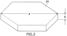
- FIG. 2 is a perspective view schematically illustrating a scaly boron nitride 3A having a hexagonal crystal shape.
- the scaly thermally conductive filler the scaly boron nitride 3A having a hexagonal crystal shape as shown in FIG. 2 is preferably used from the viewpoints of the relative permittivity and the thermal conductivity of the thermally conductive sheet 1.
- the scaly thermally conductive filler may be used alone or in combination of two or more.
- the thermally conductive sheet 1 according to the present technology can exhibit excellent thermal and dielectric properties by using a scaly thermally conductive filler (e.g., the scaly boron nitride 3A) which is less expensive than a spherical thermally conductive filler (such as spherical boron nitride) as the first thermally conductive filler 3.
- a scaly thermally conductive filler e.g., the scaly boron nitride 3A
- a spherical thermally conductive filler such as spherical boron nitride
- the average particle size (D50) of the scaly thermally conductive filler is not particularly limited and may be appropriately selected according to the purpose.
- the lower limit of the average particle size of the scaly thermally conductive filler may be 10 ⁇ m or more, 20 ⁇ m or more, 30 ⁇ m or more, or 35 ⁇ m or more.
- the upper limit of the average particle size of the scaly thermally conductive filler may be 150 ⁇ m or less, 100 ⁇ m or less, 90 ⁇ m or less, 80 ⁇ m or less, 70 ⁇ m or less, 50 ⁇ m or less, and 45 ⁇ m or less.
- the average particle size of the scaly thermally conductive filler is preferably 20 to 100 ⁇ m.
- the D50 of the fibrous thermally conductive filler is not particularly limited and may be appropriately selected according to the purpose, for example, 20 to 250 ⁇ m.
- the aspect ratio (average major diameter / average minor diameter) of the first thermally conductive filler 3 is not particularly limited and may be appropriately selected according to the purpose.
- the aspect ratio of the scaly thermally conductive filler may be in the range of 10 to 100.
- the average major diameter and average minor diameter of the first thermally conductive filler 3 can be measured by, for example, a microscope, a scanning electron microscope (SEM), or a particle size distribution meter.
- SEM scanning electron microscope
- the average value may be calculated by arbitrarily selecting 200 or more boron nitrides 3A from an image captured by a SEM, and determining the respective ratios of the major diameter a to the minor diameter b (a/b).
- the content of the first thermally conductive filler 3 in the thermally conductive sheet 1 is not particularly limited and may be appropriately selected according to the purpose.
- the lower limit of the content of the first thermally conductive filler 3 in the thermally conductive sheet 1 may be 15% by volume or more, 20% by volume or more, or 25% by volume or more.
- the upper limit of the content of the first thermally conductive filler 3 in the thermally conductive sheet 1 may be 45% by volume or less, 40% by volume or less, 35% by volume or less, or 30% by volume or less.
- the content of the first thermally conductive filler 3 in the thermally conductive sheet 1 is preferably 20 to 35% by volume.
- the content of the first thermally conductive filler 3 in the thermally conductive sheet 1 is preferably 20% by volume or more and less than 40% by volume, and more preferably 20 to 27% by volume.
- the second thermally conductive filler 4 is a thermally conductive filler other than the first thermally conductive filler 3 described above.
- the second thermally conductive filler 4 is non-scaly and non-fibrous, and includes, for example, a spherical, powdery, granular, or flat thermally conductive filler.
- the material of the second thermally conductive filler 4 is preferably a material capable of ensuring the insulating property of the thermally conductive sheet 1 in consideration of the effects of the present technology, and may include aluminum oxide (alumina, sapphire), aluminum nitride, boron nitride, zirconia, and silicon carbide, among others.
- the second thermally conductive filler 4 may be used alone or in combination of two or more.
- the second thermally conductive filler 4 aluminum nitride particles and spherical alumina particles are preferably used in combination from the viewpoint of the relative permittivity and thermal conductivity of the thermally conductive sheet 1.
- the average particle size of the aluminum nitride particles is preferably 1 to 5 ⁇ m, may be 1 to 3 ⁇ m, and may be 1 to 2 ⁇ m.
- the average particle size of the spherical alumina particles is preferably 1 to 3 ⁇ m, and may be 1.5 to 2.5 ⁇ m.
- the content of the second thermally conductive filler 4 in the thermally conductive sheet 1 is not particularly limited and may be appropriately selected according to the purpose.
- the lower limit of the content of the second thermally conductive filler 4 in the thermally conductive sheet 1 may be 10% by volume or more, 15% by volume or more, or 20% by volume or more.
- the upper limit of the content of the second thermally conductive filler 4 in the thermally conductive sheet 1 may be 50% by volume or less, 40% by volume or less, 30% by volume or less, or 25% by volume or less.
- the total content of the second thermally conductive filler 4 in the thermally conductive sheet 1 may be, for example, 30 to 60% by volume.
- the content of the spherical alumina particles in the thermally conductive sheet 1 is preferably 10 to 45% by volume from the viewpoint of viscosity reduction of the thermally conductive sheet 1 before thermosetting.
- the content of the spherical alumina particles is preferably 10 to 25% by volume, and the content of the aluminum nitride particles is preferably 10 to 25% by volume in the thermally conductive sheet 1 from the viewpoint of viscosity reduction of the thermally conductive sheet 1 before thermosetting.
- the thermally conductive sheet 1 may further contain components other than those described above to the extent that the effects of the present technology are not impaired.
- the other components may include a dispersant, a curing accelerator, a retarder, a tackifier, a plasticizer, a flame retardant, an antioxidant, a stabilizer, and a colorant,
- the thermally conductive sheet 1 in which the first thermally conductive filler 3 and the second thermally conductive filler 4 are dispersed in the binder resin 2 relative permittivity and thermal conductivity in the thickness direction B shown in FIG. 1 of the thermally conductive sheet and relative permittivity and thermal conductivity in the surface direction A shown in FIG. 1 of the thermally conductive sheet are different.
- the second thermally conductive filler 4 can support the orientation of the first thermally conductive filler 3, so that the first thermally conductive filler 3 can be oriented in the thickness direction B of the thermally conductive sheet 1 as well as possible.
- the first thermally conductive filler 3 is oriented in the thickness direction B of the thermally conductive sheet 1, the thermal conductivity in the thickness direction B is larger than the thermal conductivity in the surface direction A, and the relative permittivity in the thickness direction B is larger than the relative permittivity in the surface direction A.
- the thermal conductivity in the orientation direction (for example, the thickness direction B of the thermally conductive sheet 1) of the first thermally conductive filler 3 may be twice or more the thermal conductivity in the non-orientation direction (for example, the surface direction A of the thermally conductive sheet 1) of the first thermally conductive filler 3.
- the thermal conductivity of the thermally conductive sheet 1 in the thickness direction B may be, for example, 1 W/m ⁇ K or more, 4 W/m ⁇ K or more, 7 W/m ⁇ K or more, or 9 W/m ⁇ K or more.
- the thermal conductivity of the thermally conductive sheet 1 in the surface direction A may be, for example, 1 W/m ⁇ K or more, 3 W/m ⁇ K or more, or 3.5 W/m ⁇ K or more.
- the relative permittivity (30 GHz) of the thermally conductive sheet 1 in the thickness direction B may be, for example, 4.0 or more, 5.0 or more, 30 or more, or 60 or more.
- the relative permittivity (30 GHz) of the thermally conductive sheet 1 in the surface direction A may be, for example, 3.0 or more, 4.0 or more, 4.5 or more, 10 or more, or 20 or more.
- the thermal conductivity and relative permittivity of the thermally conductive sheet can be measured by the method described in the examples described below.
- the average thickness of the thermally conductive sheet 1 is not particularly limited and may be appropriately selected according to the purpose.
- the lower limit of the average thickness of the thermally conductive sheet may be 0.05 mm or more, or 0.1 mm or more.
- the upper limit of the average thickness of the thermally conductive sheet may be 5 mm or less, 4 mm or less, or 3 mm or less.
- the average thickness of the thermally conductive sheet 1 is preferably 0.1 to 4 mm.
- the average thickness of the thermally conductive sheet 1 can be obtained, for example, from the arithmetic average value of the thickness of the thermally conductive sheet measured at arbitrary five points.
- a method for manufacturing a thermally conductive sheet according to the present technology includes the following steps A, B, and C.
- a resin composition for forming a thermally conductive sheet is prepared by dispersing a first thermally conductive filler 3 and a second thermally conductive filler 4 in a binder resin 2.
- the resin composition for forming a thermally conductive sheet can be prepared by uniformly mixing the first thermally conductive filler 3, the second thermally conductive filler 4, and the binder resin 2, as well as various additives and volatile solvents as necessary by a known method.
- a molded block is formed from the prepared resin composition for forming a thermally conductive sheet.
- the method of forming the molded block include an extrusion molding method and an in-mold molding method.
- the extrusion molding method and the in-mold molding method are not particularly limited and may be suitably employed among various known extrusion molding methods and in-mold molding methods depending on the viscosity of the resin composition for forming a thermally conductive sheet and characteristics required for the thermally conductive sheet.
- the binder resin flows and the first thermally conductive filler 3 is oriented along the flow direction.
- uncured sheets may be prepared from the resin composition for forming a thermally conductive sheet by using a bar coater, and the green sheets may be laminated to form a molded block.
- the green sheets are obtained by making a 50 to 500 ⁇ m thick sheet by using a bar coater and drying the sheet in an oven at 80 to 120 °C for 5 to 20 minutes.
- uncured green sheets are laminated at a desired height to form a laminate. Then the laminate is further cured to form the molded block.
- the size and shape of the molded block can be determined in accordance with the size of the thermally conductive sheet 1. For example, this may be a cuboid having a cross section of 0.5 to 15 cm in length and 0.5 to 15 cm in width. The length of the cuboid may be determined as necessary.
- step C the molded block is sliced into a sheet shape to obtain thermally conductive sheet in which relative permittivity and thermal conductivity in the thickness direction of the thermally conductive sheet and relative permittivity and thermal conductivity in the surface direction of the thermally conductive sheet are different.
- the first thermally conductive filler 3 is exposed on the surface (slice surface) of the sheet obtained by the slice.
- the slicing method is not particularly limited and may be suitably selected from known slicing devices (preferably ultrasonic cutters) according to the size and mechanical strength of the molded block.
- the slice direction of the molded block is preferably 60 to 120 degrees relative to the extrusion direction, more preferably 70 to 100 degrees, and even more preferably 90 degrees (perpendicular).
- the slice direction of the molded block is not particularly limited and may be appropriately selected according to the purpose of use of the thermally conductive sheet 1.
- the manufacturing method of the thermally conductive sheet having step A, step B, and step C can produce the thermally conductive sheet 1 containing the binder resin 2, the first thermally conductive filler 3, and the second thermally conductive filler 4, in which the first thermally conductive filler 3 and the second thermally conductive filler 4 are dispersed in the binder resin 2, and relative permittivity and thermal conductivity in the thickness direction B and relative permittivity and thermal conductivity in the surface direction A are different.
- the method for manufacturing the thermally conductive sheet according to the present technology is not limited to the above-described example, and may further include, for example, step D of pressing the slice surface after step C.
- step D of pressing the slice surface after step C.
- the pressing step D By including the pressing step D in the manufacturing method of the thermally conductive sheet, the surface of the sheet obtained in step C is smoothed more, and the adhesion with other members can be further improved.
- a pressing method a device comprising a pair of a pressing flat plate and a flat press head can be used. Further, the sheet may be pressed by a pinch roll.
- the pressure of pressing may be, for example, 0.1 to 100 MPa.
- the pressing is preferably carried out at or above the glass transition temperature (Tg) of the binder resin 2.
- the press temperature may be 0 to 180 °C, within a temperature range from room temperature (e.g., 25 °C) to 100 °C, or 30 to 100 °C.
- the thermally conductive sheet according to the present technology can be, for example, disposed between a heat-generating element and a heat-dissipating element, thereby forming an electronic device (thermal device) having a structure in which the thermally conductive sheet is disposed between the heat-generating element and the heat-dissipating element for releasing heat generated by the heat-generating element to the heat-dissipating element.
- the electronic device includes at least the heat-generating element, the heat-dissipating element, and the thermally conductive sheet, and may further include other components if necessary.
- the heat-generating element is not particularly limited, and includes, for example, an integrated circuit element such as a CPU (Central Processing Unit), a GPU (Graphics Processing Unit), a DRAM (Dynamic Random Access Memory), and a flash memory, and electronic components which generate heat in an electric circuit such as a transistor and a resistor.
- the heat-generating element also includes a component for receiving an optical signal such as an optical transceiver in a communication device.
- the heat-dissipating element is not particularly limited and may include components such as a heat sink or a heat spreader used in combination with an integrated circuit element, a transistor, or an optical transceiver housing, among others.
- the heat-dissipating element may be any components that conduct heat generated in a heat source to dissipate the heat to the outside, such as a heat radiator, a cooler, a die pad, a printed circuit board, a cooling fan, a Peltier element, a heat pipe, a metal cover, and a housing.
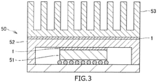
- FIG. 3 is a cross-sectional view illustrating an example of a semiconductor device 50 to which the thermally conductive sheet 1 according to the present technology is applied.
- the thermally conductive sheet 1 is mounted on a semiconductor device 50 incorporated in various electronic devices, and sandwiched between a heat-generating element and a heat-dissipating element.
- the semiconductor device 50 shown in FIG. 3 includes an electronic component 51, a heat spreader 52, and a thermally conductive sheet 1, and the thermally conductive sheet 1 is held between the heat spreader 52 and the electronic component 51.
- the thermally conductive sheet 1 sandwiched between the heat spreader 52 and the heat sink 53 can constitute a heat-dissipating member for dissipating heat of the electronic component 51 together with the heat spreader 52.
- the mounting place of the thermally conductive sheet 1 is not limited to between the heat spreader 52 and the electronic component 51, or between the heat spreader 52 and the heat sink 53, and may be appropriately selected according to the constitution of the electronic device or the semiconductor device.
- thermally conductive sheets were prepared, and each of the relative permittivity and thermal conductivity in the thickness direction and the surface direction of the thermally conductive sheet were measured.
- the present technology is not limited to these examples.
- a resin composition for forming a thermally conductive sheet is prepared by uniformly mixing 33% by volume of silicone resin, 27% by volume of scaly boron nitride (D50: 40 ⁇ m) having a hexagonal crystal shape, 20% by volume of aluminum nitride (D50: 1.2 ⁇ m), and 20% by volume of spherical alumina particles (D50: 2 ⁇ m).
- the resin composition for forming a thermally conductive sheet was poured into a mold (opening: 50 mm x 50 mm) having a cuboid internal space by an extrusion molding method and heated in an oven at 60 °C for 4 hours to form a molded block.
- the inner surface of the mold was release-treated by attaching a releasable polyethylene terephthalate film.
- the molded block thus obtained was sliced into a sheet having a thickness of 1 mm by an ultrasonic cutter in a direction perpendicular to the length direction of the obtained molded block, thereby obtaining a thermally conductive sheet in which scaly boron nitride was oriented in the thickness direction of the sheet.
- a thermally conductive sheet was obtained by the same method as in Example 1 except that a resin composition for forming a thermally conductive sheet was prepared by uniformly mixing 37% by volume of silicone resin, 23% by volume of scaly boron nitride (D50: 40 ⁇ m) having a hexagonal crystal shape, 20% by volume of aluminum nitride (D50: 1.2 ⁇ m), and 20% by volume of spherical alumina particles (D50: 2 ⁇ m).
- a resin composition for forming a thermally conductive sheet was prepared by uniformly mixing 37% by volume of silicone resin, 23% by volume of scaly boron nitride (D50: 40 ⁇ m) having a hexagonal crystal shape, 20% by volume of aluminum nitride (D50: 1.2 ⁇ m), and 20% by volume of spherical alumina particles (D50: 2 ⁇ m).
- a thermally conductive sheet was obtained by the same method as in Example 1 except that a resin composition for forming a thermally conductive sheet was prepared by uniformly mixing 60% by volume of silicone resin, 20% by volume of scaly boron nitride (D50: 40 ⁇ m) having a hexagonal crystal shape, 10% by volume of aluminum nitride (D50: 1.2 ⁇ m), and 10% by volume of spherical alumina particles (D50: 2 ⁇ m).
- a resin composition for forming a thermally conductive sheet was prepared by uniformly mixing 60% by volume of silicone resin, 20% by volume of scaly boron nitride (D50: 40 ⁇ m) having a hexagonal crystal shape, 10% by volume of aluminum nitride (D50: 1.2 ⁇ m), and 10% by volume of spherical alumina particles (D50: 2 ⁇ m).
- a thermally conductive sheet having carbon fibers oriented in the thickness direction of the sheet was obtained by the same method as in Example 1, except that a resin composition for forming a thermally conductive sheet was prepared by uniformly mixing 35% by volume of silicone resin, 23% by volume of carbon fibers (D50: 150 ⁇ m), and 42% by volume of spherical alumina particles (D50: 3 ⁇ m), and that a molded block was formed by heating the composition in an oven at 100 °C for 6 hours.
- a resin composition for forming a thermally conductive sheet is prepared by uniformly mixing 33% by volume of silicone resin, 27% by volume of scaly boron nitride (D50: 40 ⁇ m) having a hexagonal crystal shape, 20% by volume of aluminum nitride (D50: 1.2 ⁇ m), and 20% by volume of spherical alumina particles (D50: 2 ⁇ m).
- a sheet having a thickness of 1 mm was prepared by using a bar coater and cured in an oven at 60 °C for 30 minutes to obtain uncured green sheets, and the sheets were laminated to form a laminate of 50 mm x 50 mm and heated in an oven at 60 °C for 4 hours to form a molded block.
- the molded block thus obtained was sliced into a sheet having a thickness of 1 mm by using an ultrasonic cutter to obtain a thermally conductive sheet in which scaly boron nitride was oriented in the thickness direction of the sheet.
- a resin composition for forming a thermally conductive sheet is formed by uniformly mixing 33% by volume of silicone resin, 27% by volume of scaly boron nitride (D50: 40 ⁇ m) having a hexagonal crystal shape, 20% by volume of aluminum nitride (D50: 1.2 ⁇ m), and 20% by volume of spherical alumina particles (D50: 2 ⁇ m).
- a laminate of 50 mm x 50 mm was prepared by using a die head (opening: height 1 mm x slit width 0.5 mm) and heated in an oven at 60 °C for 4 hours to form a molded block.
- the molded block thus obtained was sliced into a 1 mm thick sheet by an ultrasonic cutter to obtain a thermally conductive sheet in which scaly boron nitride was oriented in the thickness direction of the sheet.
- a thermally conductive sheet was obtained by the same method as in Example 1, except that a resin composition for forming a thermally conductive sheet was prepared by uniformly mixing 60% by volume of silicone resin, 20% by volume of spherical boron nitride (D50: 25 ⁇ m), 10% by volume of aluminum nitride (D50: 1.2 ⁇ m), and 10% by volume of spherical alumina particles (D50: 2 ⁇ m).
- a thermally conductive sheet was obtained by the same method as in Example 1, except that a resin composition for forming a thermally conductive sheet was prepared by uniformly mixing 60% by volume of silicone resin, 20% by volume of spherical boron nitride (D50: 50 ⁇ m), 10% by volume of aluminum nitride (D50: 1.2 ⁇ m), and 10% by volume of spherical alumina particles (D50: 2 ⁇ m).
- a thermally conductive sheet was obtained by the same method as in Example 1, except that a resin composition for forming a thermally conductive sheet was prepared by uniformly mixing 60% by volume of silicone resin and 40% by volume of scaly boron nitride (D50: 40 ⁇ m) having a hexagonal crystal shape.
- a resin composition for forming a thermally conductive sheet was prepared by uniformly mixing 60% by volume of silicone resin and 40% by volume of scaly boron nitride (D50: 40 ⁇ m) having a hexagonal crystal shape.
- the effective thermal conductivities (W/m ⁇ K) in the thickness direction and in the surface direction of the thermally conductive sheet were measured at a load of 1 kgf/cm 2 by using a thermal resistance measuring device conforming to ASTM-D 5470.
- the results are shown in Table 1.
- "thickness direction” and "surface direction” represent the measurement direction of the effective thermal conductivity in the thermally conductive sheet.
- the direction in which carbon fibers and scaly boron nitride are oriented in the sheet is the "thickness direction” and the direction perpendicular to the thickness direction is the "surface direction”.
- Examples 1 to 6 could produce a thermally conductive sheet containing a binder resin, a first thermally conductive filler, and a second thermally conductive filler, in which the first scaly thermally conductive filler and the second thermally conductive filler are dispersed in the binder resin, and relative permittivity and thermal conductivity in the thickness direction and relative permittivity and thermal conductivity in the surface direction are different.
- the thermally conductive sheets obtained in Examples 1 to 6 were found to have an anisotropy of the relative permittivity and the thermal conductivity in the thickness direction and the surface direction.
- thermally conductive sheets obtained in Examples 1 to 6 had a thermal conductivity in the orientation direction (thickness direction) of the first thermally conductive filler of twice or more that in the non-orientation direction (surface direction) of the first thermally conductive filler.
- Comparative Examples 1 and 2 it was found that the resin composition containing no first thermally conductive filler could not form a thermally conductive sheet in which relative permittivity and thermal conductivity in the thickness direction and relative permittivity and thermal conductivity in the surface direction are different. In other words, it was found that the thermally conductive sheets obtained in Comparative Examples 1 and 2 did not have anisotropy of relative permittivity and thermal conductivity in the thickness direction and the surface direction.
- Comparative Example 3 it was found that the resin composition containing no second thermally conductive filler could not form a thermally conductive sheet in which relative permittivity and thermal conductivity in the thickness direction and relative permittivity and thermal conductivity in the surface direction are different. Specifically, it was found that the thermally conductive sheet obtained in Comparative Example 3 did not have an anisotropy of the relative permittivity in the thickness direction and the surface direction.
- thermally conductive sheet according to the present technology has different relative permittivity and thermal conductivity in the thickness direction and the surface direction, new applications can be expected, for example, in the field of shield and antenna.
- thermally conductive sheet 1 thermally conductive sheet, 2 binder resin, 3 first thermally conductive filler, 3A scaly boron nitride, 4 second thermally conductive filler, 50 semiconductor device, 51 electronic component, 52 heat spreader, 53 heat sink
Landscapes
- Chemical & Material Sciences (AREA)
- Chemical Kinetics & Catalysis (AREA)
- Organic Chemistry (AREA)
- Health & Medical Sciences (AREA)
- Medicinal Chemistry (AREA)
- Polymers & Plastics (AREA)
- Engineering & Computer Science (AREA)
- Manufacturing & Machinery (AREA)
- Materials Engineering (AREA)
- Mechanical Engineering (AREA)
- Physics & Mathematics (AREA)
- Thermal Sciences (AREA)
- Inorganic Chemistry (AREA)
- Microelectronics & Electronic Packaging (AREA)
- Combustion & Propulsion (AREA)
- Cooling Or The Like Of Semiconductors Or Solid State Devices (AREA)
- Compositions Of Macromolecular Compounds (AREA)
Abstract
Description
- The present technology relates to a thermally conductive sheet and a method for manufacturing a thermally conductive sheet. This application claims priority based on
Japanese Application No. 2020-86074 filed on May 15, 2020 Japanese Application No. 2020-149489 filed on September 4, 2020 - With the enhancement of the performance of electronic appliances, the density and integration of semiconductor devices are increasing. Accordingly, it is important to more efficiently dissipate heat generated by electronic components constituting the electronic appliances. For example, in a semiconductor device, an electronic component is attached to a heat sink such as a heat radiation fan or a heat radiation plate through a thermally conductive sheet in order to efficiently dissipate heat. As a thermally conductive sheet, for example, there is widely used a silicone resin in which a filler such as an inorganic filler is contained (dispersed). Further improvement in thermal conductivity is required for a heat radiating member such as this thermally conductive sheet. For example, in order to increase the thermal conductivity of a thermally conductive sheet, it has been considered to increase the filling ratio of the inorganic filler blended in a matrix such as a binder resin. However, increasing the filling ratio of the inorganic filler will impair the flexibility of the thermally conductive sheet and cause powder fall, so that there is a limit in increasing the filling ratio of the inorganic filler.
- Examples of the inorganic filler include alumina, aluminum nitride, and aluminum hydroxide. Further, in order to increase the thermal conductivity, scaly particles such as boron nitride and graphite, and carbon fibers may be filled in the matrix. This is due to the anisotropy of the thermal conductivity of the scaly particles or the like. For example, carbon fibers are known to have a thermal conductivity of about 600 to 1,200 W/m∗K in the fiber direction. In addition, boron nitride is known to have a thermal conductivity of about 110 W/m∗K in the surface direction and a thermal conductivity of about 2 W/m∗K in the direction perpendicular to the surface direction. Thus, the thermal conductivity is expected to be remarkably improved by making the fiber direction of the carbon fiber and the surface direction of the scaly particles the same as the thickness direction of the sheet, which is the heat transfer direction, in other words, by orienting the carbon fiber and the scaly particles in the thickness direction of the sheet.
- In recent years, from the viewpoint of electromagnetic wave control in a communication device such as a cellular phone, there has been a demand for a heat radiation material in which the relative permittivity as well as the thermal conductivity is controlled.
- Patent Document 1:
Japanese Unexamined Patent Application Publication No. 06-38460 - The present technology is proposed in view of such conventional circumstances, and provides a thermally conductive sheet in which relative permittivity and thermal conductivity in the thickness direction and relative permittivity and thermal conductivity in the surface direction are different, and a method for manufacturing the thermally conductive sheet.
- A thermally conductive sheet according to the present technology includes a binder resin; a first thermally conductive filler comprising a scaly thermally conductive filler and/or a fibrous thermally conductive filler; and a second thermally conductive filler comprising a non-scaly and non-fibrous thermally conductive filler, the first thermally conductive filler and the second thermally conductive filler being dispersed in the binder resin, wherein relative permittivity and thermal conductivity in the thickness direction of the thermally conductive sheet and relative permittivity and thermal conductivity in the surface direction of the thermally conductive sheet are different.
- A method for manufacturing a thermally conductive sheet according to the present invention includes: step A of preparing a resin composition for forming a thermally conductive sheet by dispersing a first thermally conductive filler comprising a scaly thermally conductive filler and/or a fibrous thermally conductive filler and a second thermally conductive filler comprising a non-scaly and non-fibrous thermally conductive filler in a binder resin; step B of forming a molded block from the resin composition for forming a thermally conductive sheet; and a step C of slicing the molded block into a sheet shape to obtain a thermally conductive sheet in which relative permittivity and thermal conductivity in the thickness direction of the thermally conductive sheet and relative permittivity and thermal conductivity in the surface direction of the thermally conductive sheet are different.
- According to the present technology, it is possible to provide a thermally conductive sheet in which relative permittivity and thermal conductivity in the thickness direction and relative permittivity and thermal conductivity in the surface direction are different.
-
- FIG. 1 is a cross-sectional view illustrating an example of a thermally conductive sheet according to the present technology.
- FIG. 2 is a perspective view schematically illustrating a scaly boron nitride having a hexagonal crystal shape.
- FIG. 3 is a cross-sectional view illustrating an example of a semiconductor device to which a thermally conductive sheet according to the present technology is applied.
- In the present specification, the average particle size (D50) of the thermally conductive filler is the diameter value in microns where half of the population of the particles of the thermally conductive filler resides below this point, in other words, the diameter at which, in the cumulative curve obtained with the total area of the population of the thermally conductive filler being 100%, the cumulative value is 50% from the small particle size side of the particle size distribution of the thermally conductive filler. In the case where the thermally conductive filler is a fibrous thermally conductive filler, D50 means the fiber length in microns where half of the population of the fibers of the fibrous thermally conductive filler resides below this point, in other words, the fiber length at which, in the cumulative curve obtained with the total area of the population of the fibrous thermally conductive filler being 100%, the cumulative value is 50%. The particle size distribution (particle diameter distribution) in this specification is obtained by volume basis. Examples of the method for measuring the particle size distribution include a method that uses a laser diffraction type particle size distribution measuring device.
-
FIG. 1 is a cross-sectional view illustrating an example of a thermallyconductive sheet 1 according to the present technology. The thermallyconductive sheet 1 contains abinder resin 2, a first thermally conductive filler 3 comprising a scaly thermally conductive filler and/or a fibrous thermally conductive filler, and a second thermallyconductive filler 4 comprising a non-scaly and non-fibrous thermally conductive filler, wherein the first thermally conductive filler 3 and the second thermallyconductive filler 4 are dispersed in thebinder resin 2. Further, relative permittivity and thermal conductivity in the thickness direction B of the thermallyconductive sheet 1 and relative permittivity and thermal conductivity in the surface direction A of the thermallyconductive sheet 1 are different; in other words, the thermallyconductive sheet 1 has anisotropic relative permittivity and thermal conductivity in the thickness direction B and the surface direction A. As described above, since the relative permittivity is controlled together with the thermal conductivity, the thermallyconductive sheet 1 can be expected to have new applications, for example, in the field of shielding and antennas. The components of the thermallyconductive sheet 1 will be described below. - The
binder resin 2 is used for holding the first thermally conductive filler 3 and the second thermallyconductive filler 4 in the thermallyconductive sheet 1. Thebinder resin 2 is selected according to characteristics such as mechanical strength, heat resistance, and electrical properties required for the thermallyconductive sheet 1. Thebinder resin 2 may be selected from a thermoplastic resin, a thermoplastic elastomer, and a thermosetting resin. - Examples of the thermoplastic resin include polyethylene, polypropylene, ethylene-aolefin copolymer such as ethylene-propylene copolymer, polymethylpentene, polyvinyl chloride, polyvinylidene chloride, polyvinyl acetate, ethylene-vinyl acetate copolymer, polyvinyl alcohol, polyvinyl acetal, fluoropolymers such as polyvinylidene fluoride and polytetrafluoroethylene, polyethylene terephthalate, polybutylene terephthalate, polyethylene naphthalate, polystyrene, polyacrylonitrile, styrene-acrylonitrile copolymer, acrylonitrile-butadiene-styrene copolymer (ABS) resin, polyphenylene ether copolymer (PPE) resin, modified PPE resin, aliphatic polyamides, aromatic polyamides, polyimide, polyamideimide, polymethacrylic acid, polymethacrylate esters such as polymethacrylic acid methyl ester, polyacrylic acids, polycarbonate, polyphenylene sulfide, polysulfone, polyether sulfone, polyether nitrile, polyether ketone, polyketone, liquid crystal polymer, silicone resin, and ionomer.
- Examples of the thermoplastic elastomer include a styrene-butadiene block copolymer or a hydrogenated product thereof, a styrene-isoprene block copolymer or a hydrogenated product thereof, a styrene-based thermoplastic elastomer, an olefin-based thermoplastic elastomer, a vinyl chloride-based thermoplastic elastomer, a polyester-based thermoplastic elastomer, a polyurethane-based thermoplastic elastomer, and a polyamide-based thermoplastic elastomer.
- Examples of the thermosetting resin include crosslinked rubber, epoxy resin, phenol resin, polyimide resin, unsaturated polyester resin, and diallyl phthalate. Examples of the crosslinked rubber include natural rubber, acrylic rubber, butadiene rubber, isoprene rubber, styrene-butadiene copolymer rubber, nitrile rubber, hydrogenated nitrile rubber, chloroprene rubber, ethylene-propylene copolymer rubber, chlorinated polyethylene rubber, chlorosulfonated polyethylene rubber, butyl rubber, halogenated butyl rubber, fluororubber, urethane rubber, and silicone rubber.
- As the
binder resin 2, for example, silicone resin is preferable in view of adhesion between the heat-generating surface of the electronic component and the heat sink surface. Examples of the silicone resin may include a two-part addition reaction type silicone resin comprising a silicone having an alkenyl group as a main component, a main agent containing a curing catalyst, and a curing agent having a hydrosilyl group (Si-H group). Examples of the silicone having an alkenyl group may include a polyorganosiloxane having a vinyl group. The curing catalyst is a catalyst for promoting an addition reaction between an alkenyl group in the silicone having the alkenyl group and a hydrosilyl group in the curing agent having the hydrosilyl group. Examples of the curing catalyst include catalysts known as catalysts used in hydrosilylation reaction, for example, a platinum group-based curing catalyst such as a platinum group metal single substance such as platinum, rhodium, and palladium, or platinum chloride. Examples of the curing agent having the hydrosilyl group include a polyorganosiloxane having a hydrosilyl group. Thebinder resin 2 may be used alone or in combination of two or more. - The content of the
binder resin 2 in the thermallyconductive sheet 1 is not particularly limited and may be appropriately selected according to the purpose. For example, the lower limit of the content of thebinder resin 2 in the thermallyconductive sheet 1 may be 20% by volume or more, 25% by volume or more, or 30% by volume or more. The upper limit of the content of thebinder resin 2 in the thermallyconductive sheet 1 may be 70% by volume or less, 60% by volume or less, or 50% by volume or less. From the viewpoint of flexibility of the thermallyconductive sheet 1, the content of thebinder resin 2 in the thermallyconductive sheet 1 is preferably 25 to 60% by volume. - The first thermally conductive filler 3 may be a scaly thermally conductive tiller, a fibrous thermally conductive filler, or a combination of the scaly thermally conductive filler and the fibrous thermally conductive filler.
- The scaly thermally conductive filler has a high aspect ratio and an isotropic thermal conductivity in the surface direction. The scaly thermally conductive filler is not particularly limited as long as it is scaly, and may include boron nitride (BN), mica, alumina, aluminum nitride, silicon carbide, silica, zinc oxide, and molybdenum disulfide, among others.
- The fibrous thermally conductive filler is not particularly limited as long as it is fibrous and has necessary thermal conductivity, and aluminum nitride fiber, ultrahigh molecular weight polyethylene fiber, and polyparaphenylene bisoxazole fiber, among others are preferable from the viewpoint of high thermal conductivity and insulating property. Further, as long as the relative permittivity of the thermally
conductive sheet 1 is not impaired, the fibrous thermally conductive filler may be conductive, such as carbon fibers or fibers made of a metal (such as copper, stainless steel, or nickel). -
FIG. 2 is a perspective view schematically illustrating ascaly boron nitride 3A having a hexagonal crystal shape. As the scaly thermally conductive filler, thescaly boron nitride 3A having a hexagonal crystal shape as shown inFIG. 2 is preferably used from the viewpoints of the relative permittivity and the thermal conductivity of the thermallyconductive sheet 1. The scaly thermally conductive filler may be used alone or in combination of two or more. The thermallyconductive sheet 1 according to the present technology can exhibit excellent thermal and dielectric properties by using a scaly thermally conductive filler (e.g., thescaly boron nitride 3A) which is less expensive than a spherical thermally conductive filler (such as spherical boron nitride) as the first thermally conductive filler 3. - The average particle size (D50) of the scaly thermally conductive filler is not particularly limited and may be appropriately selected according to the purpose. For example, the lower limit of the average particle size of the scaly thermally conductive filler may be 10 µm or more, 20 µm or more, 30 µm or more, or 35 µm or more. The upper limit of the average particle size of the scaly thermally conductive filler may be 150 µm or less, 100 µm or less, 90 µm or less, 80 µm or less, 70 µm or less, 50 µm or less, and 45 µm or less. From the viewpoint of the thermal conductivity of the thermally
conductive sheet 1, the average particle size of the scaly thermally conductive filler is preferably 20 to 100 µm. The D50 of the fibrous thermally conductive filler is not particularly limited and may be appropriately selected according to the purpose, for example, 20 to 250 µm. - The aspect ratio (average major diameter / average minor diameter) of the first thermally conductive filler 3 is not particularly limited and may be appropriately selected according to the purpose. For example, the aspect ratio of the scaly thermally conductive filler may be in the range of 10 to 100. The average major diameter and average minor diameter of the first thermally conductive filler 3 can be measured by, for example, a microscope, a scanning electron microscope (SEM), or a particle size distribution meter. As an example, when the
scaly boron nitride 3A having a hexagonal crystal shape as shown inFIG. 2 is used as the scaly thermally conductive filler, the average value may be calculated by arbitrarily selecting 200 ormore boron nitrides 3A from an image captured by a SEM, and determining the respective ratios of the major diameter a to the minor diameter b (a/b). - The content of the first thermally conductive filler 3 in the thermally
conductive sheet 1 is not particularly limited and may be appropriately selected according to the purpose. For example, the lower limit of the content of the first thermally conductive filler 3 in the thermallyconductive sheet 1 may be 15% by volume or more, 20% by volume or more, or 25% by volume or more. The upper limit of the content of the first thermally conductive filler 3 in the thermallyconductive sheet 1 may be 45% by volume or less, 40% by volume or less, 35% by volume or less, or 30% by volume or less. From the viewpoint of the thermal conductivity and flexibility of the thermallyconductive sheet 1, the content of the first thermally conductive filler 3 in the thermallyconductive sheet 1 is preferably 20 to 35% by volume. From the viewpoint of the anisotropy of the permittivity of the thermallyconductive sheet 1, the content of the first thermally conductive filler 3 in the thermallyconductive sheet 1 is preferably 20% by volume or more and less than 40% by volume, and more preferably 20 to 27% by volume. - The second thermally
conductive filler 4 is a thermally conductive filler other than the first thermally conductive filler 3 described above. The second thermallyconductive filler 4 is non-scaly and non-fibrous, and includes, for example, a spherical, powdery, granular, or flat thermally conductive filler. The material of the second thermallyconductive filler 4 is preferably a material capable of ensuring the insulating property of the thermallyconductive sheet 1 in consideration of the effects of the present technology, and may include aluminum oxide (alumina, sapphire), aluminum nitride, boron nitride, zirconia, and silicon carbide, among others. The second thermallyconductive filler 4 may be used alone or in combination of two or more. - In particular, as the second thermally
conductive filler 4, aluminum nitride particles and spherical alumina particles are preferably used in combination from the viewpoint of the relative permittivity and thermal conductivity of the thermallyconductive sheet 1. From the viewpoint of viscosity reduction of the thermallyconductive sheet 1 before thermosetting, the average particle size of the aluminum nitride particles is preferably 1 to 5 µm, may be 1 to 3 µm, and may be 1 to 2 µm. Further, from the viewpoint of viscosity reduction of the thermallyconductive sheet 1 before thermosetting, the average particle size of the spherical alumina particles is preferably 1 to 3 µm, and may be 1.5 to 2.5 µm. - The content of the second thermally
conductive filler 4 in the thermallyconductive sheet 1 is not particularly limited and may be appropriately selected according to the purpose. The lower limit of the content of the second thermallyconductive filler 4 in the thermallyconductive sheet 1 may be 10% by volume or more, 15% by volume or more, or 20% by volume or more. The upper limit of the content of the second thermallyconductive filler 4 in the thermallyconductive sheet 1 may be 50% by volume or less, 40% by volume or less, 30% by volume or less, or 25% by volume or less. The total content of the second thermallyconductive filler 4 in the thermallyconductive sheet 1 may be, for example, 30 to 60% by volume. - When spherical alumina particles are used alone as the second thermally
conductive filler 4, the content of the spherical alumina particles in the thermallyconductive sheet 1 is preferably 10 to 45% by volume from the viewpoint of viscosity reduction of the thermallyconductive sheet 1 before thermosetting. When aluminum nitride particles and spherical alumina particles are used in combination as the second thermallyconductive filler 4 as described above, the content of the spherical alumina particles is preferably 10 to 25% by volume, and the content of the aluminum nitride particles is preferably 10 to 25% by volume in the thermallyconductive sheet 1 from the viewpoint of viscosity reduction of the thermallyconductive sheet 1 before thermosetting. - The thermally
conductive sheet 1 may further contain components other than those described above to the extent that the effects of the present technology are not impaired. The other components may include a dispersant, a curing accelerator, a retarder, a tackifier, a plasticizer, a flame retardant, an antioxidant, a stabilizer, and a colorant, - As described above, in the thermally
conductive sheet 1 in which the first thermally conductive filler 3 and the second thermallyconductive filler 4 are dispersed in thebinder resin 2, relative permittivity and thermal conductivity in the thickness direction B shown inFIG. 1 of the thermally conductive sheet and relative permittivity and thermal conductivity in the surface direction A shown inFIG. 1 of the thermally conductive sheet are different. In particular, by using the first thermally conductive filler 3 and the second thermallyconductive filler 4 in combination, the second thermallyconductive filler 4 can support the orientation of the first thermally conductive filler 3, so that the first thermally conductive filler 3 can be oriented in the thickness direction B of the thermallyconductive sheet 1 as well as possible. - In the thermally
conductive sheet 1, it is preferable that the first thermally conductive filler 3 is oriented in the thickness direction B of the thermallyconductive sheet 1, the thermal conductivity in the thickness direction B is larger than the thermal conductivity in the surface direction A, and the relative permittivity in the thickness direction B is larger than the relative permittivity in the surface direction A. For example, in the thermallyconductive sheet 1, the thermal conductivity in the orientation direction (for example, the thickness direction B of the thermally conductive sheet 1) of the first thermally conductive filler 3 may be twice or more the thermal conductivity in the non-orientation direction (for example, the surface direction A of the thermally conductive sheet 1) of the first thermally conductive filler 3. The thermal conductivity of the thermallyconductive sheet 1 in the thickness direction B may be, for example, 1 W/m∗K or more, 4 W/m∗K or more, 7 W/m∗K or more, or 9 W/m∗K or more. The thermal conductivity of the thermallyconductive sheet 1 in the surface direction A may be, for example, 1 W/m∗K or more, 3 W/m∗K or more, or 3.5 W/m∗K or more. - The relative permittivity (30 GHz) of the thermally
conductive sheet 1 in the thickness direction B may be, for example, 4.0 or more, 5.0 or more, 30 or more, or 60 or more. The relative permittivity (30 GHz) of the thermallyconductive sheet 1 in the surface direction A may be, for example, 3.0 or more, 4.0 or more, 4.5 or more, 10 or more, or 20 or more. The thermal conductivity and relative permittivity of the thermally conductive sheet can be measured by the method described in the examples described below. - The average thickness of the thermally
conductive sheet 1 is not particularly limited and may be appropriately selected according to the purpose. For example, the lower limit of the average thickness of the thermally conductive sheet may be 0.05 mm or more, or 0.1 mm or more. The upper limit of the average thickness of the thermally conductive sheet may be 5 mm or less, 4 mm or less, or 3 mm or less. From the viewpoint of the handleability of the thermallyconductive sheet 1, the average thickness of the thermallyconductive sheet 1 is preferably 0.1 to 4 mm. The average thickness of the thermallyconductive sheet 1 can be obtained, for example, from the arithmetic average value of the thickness of the thermally conductive sheet measured at arbitrary five points. - A method for manufacturing a thermally conductive sheet according to the present technology includes the following steps A, B, and C.
- In step A, a resin composition for forming a thermally conductive sheet is prepared by dispersing a first thermally conductive filler 3 and a second thermally
conductive filler 4 in abinder resin 2. The resin composition for forming a thermally conductive sheet can be prepared by uniformly mixing the first thermally conductive filler 3, the second thermallyconductive filler 4, and thebinder resin 2, as well as various additives and volatile solvents as necessary by a known method. - In step B, a molded block is formed from the prepared resin composition for forming a thermally conductive sheet. Examples of the method of forming the molded block include an extrusion molding method and an in-mold molding method. The extrusion molding method and the in-mold molding method are not particularly limited and may be suitably employed among various known extrusion molding methods and in-mold molding methods depending on the viscosity of the resin composition for forming a thermally conductive sheet and characteristics required for the thermally conductive sheet.
- For example, when a resin composition for forming a thermally conductive sheet is extruded from a die in an extrusion molding method, or when a resin composition for forming a thermally conductive sheet is press-fitted into a mold for an in-mold molding method, the binder resin flows and the first thermally conductive filler 3 is oriented along the flow direction.
- In step B, uncured sheets (green sheets) may be prepared from the resin composition for forming a thermally conductive sheet by using a bar coater, and the green sheets may be laminated to form a molded block. For example, in this method, the green sheets are obtained by making a 50 to 500 µm thick sheet by using a bar coater and drying the sheet in an oven at 80 to 120 °C for 5 to 20 minutes. Next, uncured green sheets are laminated at a desired height to form a laminate. Then the laminate is further cured to form the molded block.
- The size and shape of the molded block can be determined in accordance with the size of the thermally
conductive sheet 1. For example, this may be a cuboid having a cross section of 0.5 to 15 cm in length and 0.5 to 15 cm in width. The length of the cuboid may be determined as necessary. - Step C
- In step C, the molded block is sliced into a sheet shape to obtain thermally conductive sheet in which relative permittivity and thermal conductivity in the thickness direction of the thermally conductive sheet and relative permittivity and thermal conductivity in the surface direction of the thermally conductive sheet are different. The first thermally conductive filler 3 is exposed on the surface (slice surface) of the sheet obtained by the slice. The slicing method is not particularly limited and may be suitably selected from known slicing devices (preferably ultrasonic cutters) according to the size and mechanical strength of the molded block. When the molding method is an extrusion molding method, since the first thermally conductive filler 3 may be oriented in the extrusion direction, the slice direction of the molded block is preferably 60 to 120 degrees relative to the extrusion direction, more preferably 70 to 100 degrees, and even more preferably 90 degrees (perpendicular). The slice direction of the molded block is not particularly limited and may be appropriately selected according to the purpose of use of the thermally
conductive sheet 1. - As described above, the manufacturing method of the thermally conductive sheet having step A, step B, and step C can produce the thermally
conductive sheet 1 containing thebinder resin 2, the first thermally conductive filler 3, and the second thermallyconductive filler 4, in which the first thermally conductive filler 3 and the second thermallyconductive filler 4 are dispersed in thebinder resin 2, and relative permittivity and thermal conductivity in the thickness direction B and relative permittivity and thermal conductivity in the surface direction A are different. - The method for manufacturing the thermally conductive sheet according to the present technology is not limited to the above-described example, and may further include, for example, step D of pressing the slice surface after step C. By including the pressing step D in the manufacturing method of the thermally conductive sheet, the surface of the sheet obtained in step C is smoothed more, and the adhesion with other members can be further improved. As a pressing method, a device comprising a pair of a pressing flat plate and a flat press head can be used. Further, the sheet may be pressed by a pinch roll. The pressure of pressing may be, for example, 0.1 to 100 MPa. In order to further improve the effect of pressing and to reduce the pressing time, the pressing is preferably carried out at or above the glass transition temperature (Tg) of the
binder resin 2. For example, the press temperature may be 0 to 180 °C, within a temperature range from room temperature (e.g., 25 °C) to 100 °C, or 30 to 100 °C. - The thermally conductive sheet according to the present technology can be, for example, disposed between a heat-generating element and a heat-dissipating element, thereby forming an electronic device (thermal device) having a structure in which the thermally conductive sheet is disposed between the heat-generating element and the heat-dissipating element for releasing heat generated by the heat-generating element to the heat-dissipating element. The electronic device includes at least the heat-generating element, the heat-dissipating element, and the thermally conductive sheet, and may further include other components if necessary.
- The heat-generating element is not particularly limited, and includes, for example, an integrated circuit element such as a CPU (Central Processing Unit), a GPU (Graphics Processing Unit), a DRAM (Dynamic Random Access Memory), and a flash memory, and electronic components which generate heat in an electric circuit such as a transistor and a resistor. The heat-generating element also includes a component for receiving an optical signal such as an optical transceiver in a communication device.
- The heat-dissipating element is not particularly limited and may include components such as a heat sink or a heat spreader used in combination with an integrated circuit element, a transistor, or an optical transceiver housing, among others. In addition to the heat spreader and the heat sink, the heat-dissipating element may be any components that conduct heat generated in a heat source to dissipate the heat to the outside, such as a heat radiator, a cooler, a die pad, a printed circuit board, a cooling fan, a Peltier element, a heat pipe, a metal cover, and a housing.
-
FIG. 3 is a cross-sectional view illustrating an example of asemiconductor device 50 to which the thermallyconductive sheet 1 according to the present technology is applied. For example, as shown inFIG. 3 , the thermallyconductive sheet 1 is mounted on asemiconductor device 50 incorporated in various electronic devices, and sandwiched between a heat-generating element and a heat-dissipating element. Thesemiconductor device 50 shown inFIG. 3 includes anelectronic component 51, aheat spreader 52, and a thermallyconductive sheet 1, and the thermallyconductive sheet 1 is held between theheat spreader 52 and theelectronic component 51. The thermallyconductive sheet 1 sandwiched between theheat spreader 52 and theheat sink 53 can constitute a heat-dissipating member for dissipating heat of theelectronic component 51 together with theheat spreader 52. The mounting place of the thermallyconductive sheet 1 is not limited to between theheat spreader 52 and theelectronic component 51, or between theheat spreader 52 and theheat sink 53, and may be appropriately selected according to the constitution of the electronic device or the semiconductor device. - Examples of the present technology will be described below. In the examples, thermally conductive sheets were prepared, and each of the relative permittivity and thermal conductivity in the thickness direction and the surface direction of the thermally conductive sheet were measured. The present technology is not limited to these examples.
- A resin composition for forming a thermally conductive sheet is prepared by uniformly mixing 33% by volume of silicone resin, 27% by volume of scaly boron nitride (D50: 40 µm) having a hexagonal crystal shape, 20% by volume of aluminum nitride (D50: 1.2 µm), and 20% by volume of spherical alumina particles (D50: 2 µm). The resin composition for forming a thermally conductive sheet was poured into a mold (opening: 50 mm x 50 mm) having a cuboid internal space by an extrusion molding method and heated in an oven at 60 °C for 4 hours to form a molded block. The inner surface of the mold was release-treated by attaching a releasable polyethylene terephthalate film. The molded block thus obtained was sliced into a sheet having a thickness of 1 mm by an ultrasonic cutter in a direction perpendicular to the length direction of the obtained molded block, thereby obtaining a thermally conductive sheet in which scaly boron nitride was oriented in the thickness direction of the sheet.
- A thermally conductive sheet was obtained by the same method as in Example 1 except that a resin composition for forming a thermally conductive sheet was prepared by uniformly mixing 37% by volume of silicone resin, 23% by volume of scaly boron nitride (D50: 40 µm) having a hexagonal crystal shape, 20% by volume of aluminum nitride (D50: 1.2 µm), and 20% by volume of spherical alumina particles (D50: 2 µm).
- A thermally conductive sheet was obtained by the same method as in Example 1 except that a resin composition for forming a thermally conductive sheet was prepared by uniformly mixing 60% by volume of silicone resin, 20% by volume of scaly boron nitride (D50: 40 µm) having a hexagonal crystal shape, 10% by volume of aluminum nitride (D50: 1.2 µm), and 10% by volume of spherical alumina particles (D50: 2 µm).
- Example 4
- A thermally conductive sheet having carbon fibers oriented in the thickness direction of the sheet was obtained by the same method as in Example 1, except that a resin composition for forming a thermally conductive sheet was prepared by uniformly mixing 35% by volume of silicone resin, 23% by volume of carbon fibers (D50: 150 µm), and 42% by volume of spherical alumina particles (D50: 3 µm), and that a molded block was formed by heating the composition in an oven at 100 °C for 6 hours.
- Example 5
- A resin composition for forming a thermally conductive sheet is prepared by uniformly mixing 33% by volume of silicone resin, 27% by volume of scaly boron nitride (D50: 40 µm) having a hexagonal crystal shape, 20% by volume of aluminum nitride (D50: 1.2 µm), and 20% by volume of spherical alumina particles (D50: 2 µm). A sheet having a thickness of 1 mm was prepared by using a bar coater and cured in an oven at 60 °C for 30 minutes to obtain uncured green sheets, and the sheets were laminated to form a laminate of 50 mm x 50 mm and heated in an oven at 60 °C for 4 hours to form a molded block. The molded block thus obtained was sliced into a sheet having a thickness of 1 mm by using an ultrasonic cutter to obtain a thermally conductive sheet in which scaly boron nitride was oriented in the thickness direction of the sheet.
- Example 6
- A resin composition for forming a thermally conductive sheet is formed by uniformly mixing 33% by volume of silicone resin, 27% by volume of scaly boron nitride (D50: 40 µm) having a hexagonal crystal shape, 20% by volume of aluminum nitride (D50: 1.2 µm), and 20% by volume of spherical alumina particles (D50: 2 µm). A laminate of 50 mm x 50 mm was prepared by using a die head (opening:
height 1 mm x slit width 0.5 mm) and heated in an oven at 60 °C for 4 hours to form a molded block. The molded block thus obtained was sliced into a 1 mm thick sheet by an ultrasonic cutter to obtain a thermally conductive sheet in which scaly boron nitride was oriented in the thickness direction of the sheet. - A thermally conductive sheet was obtained by the same method as in Example 1, except that a resin composition for forming a thermally conductive sheet was prepared by uniformly mixing 60% by volume of silicone resin, 20% by volume of spherical boron nitride (D50: 25 µm), 10% by volume of aluminum nitride (D50: 1.2 µm), and 10% by volume of spherical alumina particles (D50: 2 µm).
- A thermally conductive sheet was obtained by the same method as in Example 1, except that a resin composition for forming a thermally conductive sheet was prepared by uniformly mixing 60% by volume of silicone resin, 20% by volume of spherical boron nitride (D50: 50 µm), 10% by volume of aluminum nitride (D50: 1.2 µm), and 10% by volume of spherical alumina particles (D50: 2 µm).
- A thermally conductive sheet was obtained by the same method as in Example 1, except that a resin composition for forming a thermally conductive sheet was prepared by uniformly mixing 60% by volume of silicone resin and 40% by volume of scaly boron nitride (D50: 40 µm) having a hexagonal crystal shape.
- The effective thermal conductivities (W/m∗K) in the thickness direction and in the surface direction of the thermally conductive sheet were measured at a load of 1 kgf/cm2 by using a thermal resistance measuring device conforming to ASTM-D 5470. The results are shown in Table 1. In Table 1, "thickness direction" and "surface direction" represent the measurement direction of the effective thermal conductivity in the thermally conductive sheet. Further, the direction in which carbon fibers and scaly boron nitride are oriented in the sheet is the "thickness direction" and the direction perpendicular to the thickness direction is the "surface direction".
- The relative permittivities (30 GHz) in the thickness direction and the surface direction of the thermally conductive sheet were measured by a method conforming to JIS K 6911. The results are shown in Table 1.


- It was found that Examples 1 to 6 could produce a thermally conductive sheet containing a binder resin, a first thermally conductive filler, and a second thermally conductive filler, in which the first scaly thermally conductive filler and the second thermally conductive filler are dispersed in the binder resin, and relative permittivity and thermal conductivity in the thickness direction and relative permittivity and thermal conductivity in the surface direction are different. In other words, the thermally conductive sheets obtained in Examples 1 to 6 were found to have an anisotropy of the relative permittivity and the thermal conductivity in the thickness direction and the surface direction.
- It was also found that the thermally conductive sheets obtained in Examples 1 to 6 had a thermal conductivity in the orientation direction (thickness direction) of the first thermally conductive filler of twice or more that in the non-orientation direction (surface direction) of the first thermally conductive filler.
- Further, from Comparative Examples 1 and 2, it was found that the resin composition containing no first thermally conductive filler could not form a thermally conductive sheet in which relative permittivity and thermal conductivity in the thickness direction and relative permittivity and thermal conductivity in the surface direction are different. In other words, it was found that the thermally conductive sheets obtained in Comparative Examples 1 and 2 did not have anisotropy of relative permittivity and thermal conductivity in the thickness direction and the surface direction.
- Further, from Comparative Example 3, it was found that the resin composition containing no second thermally conductive filler could not form a thermally conductive sheet in which relative permittivity and thermal conductivity in the thickness direction and relative permittivity and thermal conductivity in the surface direction are different. Specifically, it was found that the thermally conductive sheet obtained in Comparative Example 3 did not have an anisotropy of the relative permittivity in the thickness direction and the surface direction.
- Since the thermally conductive sheet according to the present technology has different relative permittivity and thermal conductivity in the thickness direction and the surface direction, new applications can be expected, for example, in the field of shield and antenna.
- 1 thermally conductive sheet, 2 binder resin, 3 first thermally conductive filler, 3A scaly boron nitride, 4 second thermally conductive filler, 50 semiconductor device, 51 electronic component, 52 heat spreader, 53 heat sink
Claims (19)
- A thermally conductive sheet containing: a binder resin; a first thermally conductive filler comprising a scaly thermally conductive filler and/or a fibrous thermally conductive filler; and a second thermally conductive filler comprising a non-scaly and non-fibrous thermally conductive filler, the first thermally conductive filler and the second thermally conductive filler being dispersed in the binder resin,
wherein relative permittivity and thermal conductivity in the thickness direction of the thermally conductive sheet and relative permittivity and thermal conductivity in the surface direction of the thermally conductive sheet are different. - The thermally conductive sheet according to claim 1, wherein the first thermally conductive filler comprises scaly boron nitride.
- The thermally conductive sheet according to claim 1 or 2, wherein the second thermally conductive filler comprises aluminum nitride particles and spherical alumina particles.
- The thermally conductive sheet according to claim 2 or 3, wherein the first thermally conductive filler has an average particle size of 20 to 100 µm.
- The thermally conductive sheet according to any one of claims 1 to 4, wherein the content of the first thermally conductive filler is 20 to 35% by volume.
- The thermally conductive sheet according to claim 3, wherein the spherical alumina particles have an average particle size of 1 to 3 µm.
- The thermally conductive sheet according to claim 3 or 6, wherein the content of the spherical alumina particles is 10 to 25% by volume.
- The thermally conductive sheet according to any one of claims 3, 6, and 7, wherein the aluminum nitride particles have an average particle size of 1 to 5 µm.
- The thermally conductive sheet according to any one of claims 3, 6, and 8 wherein the content of the aluminum nitride particles is 10 to 25% by volume.
- The thermally conductive sheet according to claim 1,
wherein the first thermally conductive filler contains carbon fibers, and wherein the second thermally conductive filler comprises spherical alumina particles. - The thermally conductive sheet according to any one of claims 1 to 10, wherein the thermal conductivity in the orientation direction of the first thermally
conductive filler is twice or more of the thermal conductivity in the non-orientation direction of the first thermally conductive filler. - A method for manufacturing the thermally conductive sheet, comprising:step A of preparing a resin composition for forming a thermally conductive sheet by dispersing a first thermally conductive filler comprising a scaly thermally conductive filler and/or a fibrous thermally conductive filler and a second thermally conductive filler comprising a non-scaly and non-fibrous thermally conductive filler in a binder resin;step B of forming a molded block from the resin composition for forming a thermally conductive sheet; andstep C of slicing the molded block into a sheet shape to obtain a thermally conductive sheet in which relative permittivity and thermal conductivity in the thickness direction of the thermally conductive sheet and relative permittivity and thermal conductivity in the surface direction of the thermally conductive sheet are different.
- The method for manufacturing a thermally conductive sheet according to claim 12, wherein in step B, the molded block is formed from the resin composition for forming a thermally conductive sheet by an extrusion molding method or an in-mold molding method.
- The method according to claim 12 or 13,
wherein in step B, the molded block is formed from the resin composition for forming a thermally conductive sheet by an extrusion molding method, and
wherein in step C, the slicing direction in which the molded block is sliced into a sheet is 60 to 120 degrees with respect to the extrusion direction of the extrusion molding method. - The method according to claim 12, wherein in step B, uncured green sheets are prepared from the resin composition for forming a thermally conductive sheet, and the green sheets are laminated to form the molded block.
- The method according to claim 15, wherein in step B, the green sheets are prepared from the resin composition for forming a thermally conductive sheet by using a bar coater.
- The method according to claim 12, wherein in step B, the molded block is formed by laminating sheets obtained by using a die head from the resin composition for forming a thermally conductive sheet.
- The method for manufacturing a thermally conductive sheet according to any one of claims 15 to 17, wherein in step C, the slicing direction in which the molded block is sliced into a sheet is 60 to 120 degrees with respect to the extrusion direction of the extrusion molding method.
- An electronic device comprising:a heat-generating element;a heat-dissipating element; aa thermally conductive sheet according to any one of claims 1 to 11 and disposed between the heat-generating element and a heat-dissipating element.
Applications Claiming Priority (3)
| Application Number | Priority Date | Filing Date | Title |
|---|---|---|---|
| JP2020086074 | 2020-05-15 | ||
| JP2020149489A JP6976393B2 (en) | 2020-05-15 | 2020-09-04 | Method for manufacturing a heat conductive sheet and a heat conductive sheet |
| PCT/JP2021/016492 WO2021230047A1 (en) | 2020-05-15 | 2021-04-23 | Thermally conductive sheet, and method for manufacturing thermally conductive sheet |
Publications (2)
| Publication Number | Publication Date |
|---|---|
| EP3965150A1 true EP3965150A1 (en) | 2022-03-09 |
| EP3965150A4 EP3965150A4 (en) | 2022-08-31 |
Family
ID=78525666
Family Applications (1)
| Application Number | Title | Priority Date | Filing Date |
|---|---|---|---|
| EP21802937.9A Pending EP3965150A4 (en) | 2020-05-15 | 2021-04-23 | THERMO-CONDUCTIVE SHEET AND METHOD OF MANUFACTURING IT |
Country Status (6)
| Country | Link |
|---|---|
| US (1) | US11742258B2 (en) |
| EP (1) | EP3965150A4 (en) |
| KR (1) | KR102780005B1 (en) |
| CN (2) | CN117624899A (en) |
| TW (1) | TW202146245A (en) |
| WO (1) | WO2021230047A1 (en) |
Families Citing this family (2)
| Publication number | Priority date | Publication date | Assignee | Title |
|---|---|---|---|---|
| JP7275246B1 (en) * | 2021-12-28 | 2023-05-17 | 三菱重工業株式会社 | Fusion device and fusion method |
| JP7752544B2 (en) * | 2022-02-18 | 2025-10-10 | 信越化学工業株式会社 | Thermally conductive sheet and method for manufacturing the thermally conductive sheet |
Family Cites Families (28)
| Publication number | Priority date | Publication date | Assignee | Title |
|---|---|---|---|---|
| JPH0638460B2 (en) | 1989-11-08 | 1994-05-18 | 東海ゴム工業株式会社 | Heat dissipation sheet |
| JPH0638460A (en) | 1992-07-09 | 1994-02-10 | Sumitomo Heavy Ind Ltd | Manufacture of coil for motor, and motor using this coil |
| US6927250B2 (en) | 2002-08-15 | 2005-08-09 | Advanced Energy Technology Inc. | Graphite composites and methods of making such composites |
| JP5140302B2 (en) * | 2007-03-29 | 2013-02-06 | ポリマテック株式会社 | Thermally conductive sheet |
| JP2008255186A (en) * | 2007-04-03 | 2008-10-23 | Mitsubishi Electric Corp | Thermally conductive resin sheet and power module |
| JP2012023335A (en) | 2010-06-17 | 2012-02-02 | Sony Chemical & Information Device Corp | Thermally conductive sheet and method of producing the same |
| TWI610407B (en) * | 2010-06-17 | 2018-01-01 | 迪睿合股份有限公司 | Thermal conductive sheet and manufacturing method thereof |
| JP5749536B2 (en) | 2011-03-28 | 2015-07-15 | 電気化学工業株式会社 | Thermally conductive moldings and their applications |
| EP3790044B1 (en) * | 2012-07-07 | 2023-10-11 | Dexerials Corporation | Heat conductive sheet |
| JP6440615B2 (en) * | 2012-07-30 | 2018-12-19 | ダウ シリコーンズ コーポレーション | Thermally conductive condensation reaction curable polyorganosiloxane composition and method for preparation and use of the composition |
| JP6657616B2 (en) * | 2014-07-02 | 2020-03-04 | 住友ベークライト株式会社 | Thermal conductive sheet, cured product of thermal conductive sheet, and semiconductor device |
| JP6295238B2 (en) * | 2014-10-31 | 2018-03-14 | デクセリアルズ株式会社 | HEAT CONDUCTIVE SHEET, HEAT CONDUCTIVE SHEET MANUFACTURING METHOD, HEAT DISSIBLING MEMBER AND SEMICONDUCTOR DEVICE |
| JP2017024246A (en) * | 2015-07-21 | 2017-02-02 | 武藤工業株式会社 | Composite resin material |
| JP2017092345A (en) * | 2015-11-13 | 2017-05-25 | デクセリアルズ株式会社 | Heat conduction sheet and method of manufacturing the same, and semiconductor device |
| JP6301978B2 (en) * | 2016-01-26 | 2018-03-28 | デクセリアルズ株式会社 | HEAT CONDUCTIVE SHEET, HEAT CONDUCTIVE SHEET MANUFACTURING METHOD, HEAT DISSIBLING MEMBER AND SEMICONDUCTOR DEVICE |
| CN106084791B (en) * | 2016-06-07 | 2019-04-02 | 北京大学 | Graphene oxide/silicone rubber composite intelligent thermal conductive material and its preparation |
| JP2018073912A (en) * | 2016-10-26 | 2018-05-10 | デクセリアルズ株式会社 | HEAT CONDUCTIVE SHEET, METHOD FOR PRODUCING HEAT CONDUCTIVE SHEET, AND SEMICONDUCTOR DEVICE |
| CN106810719B (en) * | 2017-02-24 | 2019-07-16 | 中国科学院化学研究所 | A thermally functional composite material and its preparation method and application |
| EP3667718B1 (en) * | 2017-08-10 | 2021-12-22 | Denka Company Limited | Low-dielectric-constant thermally-conductive heat dissipation member |
| JPWO2019194221A1 (en) * | 2018-04-05 | 2021-06-10 | Jnc株式会社 | Composition for heat dissipation member, visible light reflective heat dissipation member, light emitting device, light emitting device |
| KR102614679B1 (en) * | 2018-06-22 | 2023-12-19 | 세키수이 폴리머텍 가부시키가이샤 | thermal conductive sheet |
| KR102924449B1 (en) | 2018-11-20 | 2026-02-09 | 세키수이 폴리머텍 가부시키가이샤 | Thermally conductive sheet and method for manufacturing the same |
| JP2020086074A (en) | 2018-11-22 | 2020-06-04 | 東洋インキScホールディングス株式会社 | Fine semiconductor particle composition and use thereof |
| JP2020149489A (en) | 2019-03-14 | 2020-09-17 | 日本電産モビリティ株式会社 | Vehicle control device |
| JP7066654B2 (en) | 2019-04-10 | 2022-05-13 | 信越化学工業株式会社 | Composition for low-dielectric heat-dissipating film and low-dielectric heat-dissipating film |
| JP7650071B2 (en) | 2019-09-30 | 2025-03-24 | 積水ポリマテック株式会社 | Thermally conductive sheet and manufacturing method thereof |
| JP2021061382A (en) * | 2019-10-09 | 2021-04-15 | Jnc株式会社 | Composition for heat dissipation member, heat dissipation member, and electronic equipment |
| CN114555714B (en) * | 2019-11-01 | 2023-05-09 | 积水保力马科技株式会社 | Heat conduction sheet and manufacturing method thereof |
-
2021
- 2021-04-23 KR KR1020227002652A patent/KR102780005B1/en active Active
- 2021-04-23 US US17/617,238 patent/US11742258B2/en active Active
- 2021-04-23 CN CN202311721317.XA patent/CN117624899A/en active Pending
- 2021-04-23 EP EP21802937.9A patent/EP3965150A4/en active Pending
- 2021-04-23 CN CN202180004799.XA patent/CN114207044A/en active Pending
- 2021-04-23 WO PCT/JP2021/016492 patent/WO2021230047A1/en not_active Ceased
- 2021-05-11 TW TW110116919A patent/TW202146245A/en unknown
Also Published As
| Publication number | Publication date |
|---|---|
| KR20220030259A (en) | 2022-03-10 |
| CN117624899A (en) | 2024-03-01 |
| EP3965150A4 (en) | 2022-08-31 |
| TW202146245A (en) | 2021-12-16 |
| CN114207044A (en) | 2022-03-18 |
| US20220262702A1 (en) | 2022-08-18 |
| KR102780005B1 (en) | 2025-03-13 |
| WO2021230047A1 (en) | 2021-11-18 |
| US11742258B2 (en) | 2023-08-29 |
Similar Documents
| Publication | Publication Date | Title |
|---|---|---|
| CN105324844B (en) | Manufacturing method of heat conduction sheet, heat conduction sheet and heat dissipation component | |
| US20110223427A1 (en) | Method of producing electrically insulating thermally conductive sheet, electrically insulating thermally conductive sheet, and heat dissipating member | |
| JP7814582B2 (en) | Thermally conductive sheet and method for manufacturing the thermally conductive sheet | |
| JP6976393B2 (en) | Method for manufacturing a heat conductive sheet and a heat conductive sheet | |
| US11742258B2 (en) | Thermally conductive sheet and method for manufacturing thermally conductive sheet | |
| US20240010898A1 (en) | Thermally conductive sheet and method for manufacturing thermally conductive sheet | |
| JP6960554B1 (en) | Method of manufacturing heat conductive sheet and heat conductive sheet | |
| US20230348679A1 (en) | Thermally conductive sheet and production method for thermally conductive sheet | |
| JP6987941B1 (en) | Method for manufacturing a heat conductive sheet and a heat conductive sheet | |
| JP6999003B1 (en) | Method for manufacturing a heat conductive sheet and a heat conductive sheet | |
| JP2022046021A (en) | Method for manufacturing a heat conductive sheet and a heat conductive sheet | |
| US20240262979A1 (en) | Thermally-conductive sheet and thermally-conductive sheet production method | |
| JP2023073998A (en) | Thermally conductive sheet and method for producing thermally conductive sheet | |
| US20240124758A1 (en) | Heat-conductive sheet, heat-conductive sheet production method, and electronic equipment | |
| CN111725162B (en) | Thermally conductive sheet, method for manufacturing thermally conductive sheet, heat dissipating component and semiconductor device | |
| JP7057845B1 (en) | Supply form of heat conductive sheet and heat conductive sheet body | |
| CN117480600A (en) | Thermal conductive sheet and manufacturing method of thermal conductive sheet | |
| CN116848179A (en) | Supply forms of thermal conductive sheets and thermal conductive sheets | |
| HK1192575A1 (en) | Method for producing thermally conductive sheet |
Legal Events
| Date | Code | Title | Description |
|---|---|---|---|
| STAA | Information on the status of an ep patent application or granted ep patent |
Free format text: STATUS: THE INTERNATIONAL PUBLICATION HAS BEEN MADE |
|
| PUAI | Public reference made under article 153(3) epc to a published international application that has entered the european phase |
Free format text: ORIGINAL CODE: 0009012 |
|
| STAA | Information on the status of an ep patent application or granted ep patent |
Free format text: STATUS: REQUEST FOR EXAMINATION WAS MADE |
|
| 17P | Request for examination filed |
Effective date: 20211202 |
|
| AK | Designated contracting states |
Kind code of ref document: A1 Designated state(s): AL AT BE BG CH CY CZ DE DK EE ES FI FR GB GR HR HU IE IS IT LI LT LU LV MC MK MT NL NO PL PT RO RS SE SI SK SM TR |
|
| STAA | Information on the status of an ep patent application or granted ep patent |
Free format text: STATUS: EXAMINATION IS IN PROGRESS |
|
| A4 | Supplementary search report drawn up and despatched |
Effective date: 20220802 |
|
| RIC1 | Information provided on ipc code assigned before grant |
Ipc: H05K 7/20 20060101ALI20220727BHEP Ipc: H01L 23/373 20060101ALI20220727BHEP Ipc: H01L 23/36 20060101AFI20220727BHEP |
|
| 17Q | First examination report despatched |
Effective date: 20220816 |
|
| DAV | Request for validation of the european patent (deleted) | ||
| DAX | Request for extension of the european patent (deleted) | ||
| RAP1 | Party data changed (applicant data changed or rights of an application transferred) |
Owner name: SEKISUI CHEMICAL CO., LTD. |