EP3964867A1 - Laser radar, and anti-jamming method therefor - Google Patents
Laser radar, and anti-jamming method therefor Download PDFInfo
- Publication number
- EP3964867A1 EP3964867A1 EP20809106.6A EP20809106A EP3964867A1 EP 3964867 A1 EP3964867 A1 EP 3964867A1 EP 20809106 A EP20809106 A EP 20809106A EP 3964867 A1 EP3964867 A1 EP 3964867A1
- Authority
- EP
- European Patent Office
- Prior art keywords
- lidar
- time
- transmitting
- echo
- local
- Prior art date
- Legal status (The legal status is an assumption and is not a legal conclusion. Google has not performed a legal analysis and makes no representation as to the accuracy of the status listed.)
- Granted
Links
Images


Classifications
-
- G—PHYSICS
- G01—MEASURING; TESTING
- G01S—RADIO DIRECTION-FINDING; RADIO NAVIGATION; DETERMINING DISTANCE OR VELOCITY BY USE OF RADIO WAVES; LOCATING OR PRESENCE-DETECTING BY USE OF THE REFLECTION OR RERADIATION OF RADIO WAVES; ANALOGOUS ARRANGEMENTS USING OTHER WAVES
- G01S7/00—Details of systems according to groups G01S13/00, G01S15/00, G01S17/00
- G01S7/48—Details of systems according to groups G01S13/00, G01S15/00, G01S17/00 of systems according to group G01S17/00
- G01S7/4804—Auxiliary means for detecting or identifying lidar signals or the like, e.g. laser illuminators
-
- G—PHYSICS
- G01—MEASURING; TESTING
- G01S—RADIO DIRECTION-FINDING; RADIO NAVIGATION; DETERMINING DISTANCE OR VELOCITY BY USE OF RADIO WAVES; LOCATING OR PRESENCE-DETECTING BY USE OF THE REFLECTION OR RERADIATION OF RADIO WAVES; ANALOGOUS ARRANGEMENTS USING OTHER WAVES
- G01S17/00—Systems using the reflection or reradiation of electromagnetic waves other than radio waves, e.g. lidar systems
- G01S17/02—Systems using the reflection of electromagnetic waves other than radio waves
- G01S17/06—Systems determining position data of a target
- G01S17/08—Systems determining position data of a target for measuring distance only
- G01S17/10—Systems determining position data of a target for measuring distance only using transmission of interrupted, pulse-modulated waves
-
- G—PHYSICS
- G01—MEASURING; TESTING
- G01S—RADIO DIRECTION-FINDING; RADIO NAVIGATION; DETERMINING DISTANCE OR VELOCITY BY USE OF RADIO WAVES; LOCATING OR PRESENCE-DETECTING BY USE OF THE REFLECTION OR RERADIATION OF RADIO WAVES; ANALOGOUS ARRANGEMENTS USING OTHER WAVES
- G01S7/00—Details of systems according to groups G01S13/00, G01S15/00, G01S17/00
- G01S7/48—Details of systems according to groups G01S13/00, G01S15/00, G01S17/00 of systems according to group G01S17/00
- G01S7/495—Counter-measures or counter-counter-measures using electronic or electro-optical means
-
- G—PHYSICS
- G01—MEASURING; TESTING
- G01S—RADIO DIRECTION-FINDING; RADIO NAVIGATION; DETERMINING DISTANCE OR VELOCITY BY USE OF RADIO WAVES; LOCATING OR PRESENCE-DETECTING BY USE OF THE REFLECTION OR RERADIATION OF RADIO WAVES; ANALOGOUS ARRANGEMENTS USING OTHER WAVES
- G01S17/00—Systems using the reflection or reradiation of electromagnetic waves other than radio waves, e.g. lidar systems
- G01S17/02—Systems using the reflection of electromagnetic waves other than radio waves
- G01S17/06—Systems determining position data of a target
- G01S17/08—Systems determining position data of a target for measuring distance only
-
- G—PHYSICS
- G01—MEASURING; TESTING
- G01S—RADIO DIRECTION-FINDING; RADIO NAVIGATION; DETERMINING DISTANCE OR VELOCITY BY USE OF RADIO WAVES; LOCATING OR PRESENCE-DETECTING BY USE OF THE REFLECTION OR RERADIATION OF RADIO WAVES; ANALOGOUS ARRANGEMENTS USING OTHER WAVES
- G01S7/00—Details of systems according to groups G01S13/00, G01S15/00, G01S17/00
- G01S7/48—Details of systems according to groups G01S13/00, G01S15/00, G01S17/00 of systems according to group G01S17/00
- G01S7/483—Details of pulse systems
- G01S7/484—Transmitters
Definitions
- the present invention relates to the technical field of lidar, in particular to a lidar and an anti-interference method for the lidar.
- Lidar ranging is based mainly on analysis of return time of pulses transmitted from the lidar itself, for example in the case of a pulsed lidar.
- a designed pulse is typically a unified single pulse or a finite sequence of encoded pulse.
- all these devices would transmit pulses with similar or even identical profiles, making it difficult to distinguish from each other and easy to cause crosstalk.
- An anti-interference method for lidar comprises:
- the random time jitter as injected is pseudo-random time jitter.
- the step of modulating a transmitting time of the lidar by injecting random time jitter at a time interval in a sequence of the transmitting time comprises:
- the step of injecting random time jitter at the time interval in the sequence of the transmitting time is to inject pseudo-random time jitter at time intervals in sequences of transmitting times of each lidar, and the pseudo-random time jitters as injected for each lidar are different.
- the unexpected echoes further comprise echoes received correspondingly when the local lidar transmits laser due to sporadic interference thereof.
- the step of identifying interference echoes according to correlation between a transmitting time of the local lidar and a receiving time of an echo received by the local lidar comprises:
- it further comprises the step of performing laser pulse coding on the lidar to modulate the laser pulse of the lidar, wherein the injecting random time jitter at a time interval in a sequence of the transmitting time is used to modulate the transmitting time of the lidar after the coding.
- the step of transmitting a laser pulse by the lidar according to a modulated transmitting time is to use a multiple pulses transmitting mechanism to transmit the laser pulse.
- the anti-interference method for the lidar as mentioned above modulates a transmitting time of the lidar by injecting random time jitter at a time interval in a sequence of the transmitting time, and causes the lidar to transmit a laser pulse according to a modulated transmitting time.
- an echo received by the lidar comprises an expected echo of the local lidar and an unexpected echo from other lidars: because the transmitting time and the expected receiving time of the echo are always in correlation, no matter whether random time jitter is injected or not, and injecting random time jitter in the transmitting time of the lidar may disrupt the correlation between the transmitting time of the local lidar and the transmitting time of other lidars; accordingly, in the case that a plurality of lasers are used together in one scenario and causes crosstalk, the anti-interference method for the lidar above can be used to fight against crosstalk to some extent.
- a lidar wherein the lidar comprises: a controller, a transmitting module and a receiving module; wherein the controller is respectively connected to the transmitting module and the receiving module;
- the controller is configured to modulate a transmitting time of the lidar by injecting random time jitter at a time interval in a sequence of the transmitting time, and cause the transmitting module to transmit a laser pulse according to a modulated transmitting time;
- the receiving module is configured to acquire a receiving time of an echo received by the lidar, the echo comprising an expected echo and an unexpected echo of the local lidar, the unexpected echo comprising echoes of other lidars due to crosstalk therewith;
- the controller is further configured to identify and remove interference echoes according to correlation between a transmitting time of the local lidar and a receiving time of an echo received by the local lidar.
- the controller comprises an FPGA or an ASIC.
- the lidar as mentioned above modulates a transmitting time of the lidar by injecting random time jitter at a time interval in a sequence of the transmitting time, and causes the lidar to transmit a laser pulse according to a modulated transmitting time.
- an echo received by the lidar comprises an expected echo of the local lidar and an unexpected echo from other lidars: because the transmitting time and the expected receiving time of the echo are always in correlation no matter whether random time jitter is injected or not, and injecting random time jitter in the transmitting time of the lidar may disrupt the correlation between the transmitting time of the local lidar and the transmitting time of other lidars; accordingly, in the case that a plurality of lasers are used together in one scenario and causes crosstalk, the lidar above can be used to fight against crosstalk to some extent.
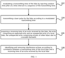
- FIG. 1 is a schematic flowchart of an anti-inference method for the lidar in an embodiment. Please refer to FIG. 1 , the method comprises steps 102 to 108:
- a transmitting time of the lidar is modulated by injecting random time jitter at a time interval in a sequence of the transmitting time.
- FIG. 2 shows a certain transmitting time point of the lidar, and the transmitting time point is the 50th ms.
- the transmitting time of the lidar can be a time sequence, that is, there are more than two transmitting time points, and the injection of pseudo-random time jitter is to insert time points at each time interval in the sequence of the transmitting time.
- the corresponding jitter amounts of these inserted time points at the original transmitting time points are defined as the pseudo-random time jitter.
- the transmitting time interval may be fixed.
- the step 102 comprises: establish a transmission timing strategy of the lidar to determine the transmitting time of the lidar; then establish a pseudo-random jitter strategy of the lidar based on the transmission timing strategy; and then modulate the transmitting time of the lidar by injecting pseudo-random time jitter at the time interval in the sequence of the transmitting time of the lidar, so as to re-determine the transmitting time of the lidar.
- Subsequent lidars transmit lasers according to the transmitting time injected with pseudo-random time jitter, that is, the lidar also transmits lasers at each pseudo-random time point.
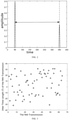
- 3 is a pseudo-random time jitter strategy established based on the 1st to Nth transmitting times of the lidar in a specific embodiment, and the vertical ordinate indicates the injected pseudo-random time jitter amount, that is, how much time it leads or lags relative to the corresponding transmitting time, where the time unit can be milliseconds. For example, -20 milliseconds indicates that the injected pseudo-random time amount is 20 milliseconds ahead of a certain transmitting time, and 20 milliseconds indicates that the injected pseudo-random time jitter is delayed relative to a certain transmitting time by 20 milliseconds.
- the lidar For the lidar to perform anti-interference in the embodiment of the present application; there can be more than two lidars provided in the same scenario, that is, each lidar in the same scenario must counteract interference of other lidars.
- the same scenario can specifically refer to more than two lidars located in the same geographic area, or refer to more than two lidars performing ranging on the same object.
- random jitter patterns therefor are different or seeds for generating random numbers are different, that is, the injected pseudo-random time jitters of different lidar are different.
- a subsequent step is to make each lidar transmit laser according to the transmitting time injected with a respective pseudo-random time jitter, and can achieve that more than two lidars in the same scenario counteract the interference of multiple lidars at the same time. For example, in the case that there are Device A, Device B and Device C in the same scenario, where Device A counteracts the crosstalk of Device B and Device C, Device B counteracts the crosstalk of Device A and Device C, and Device C counteracts the crosstalk of Device A and Device B.
- the jitter of the local lidar regarding transmitting time of each device is different from the jitter of the echo times of other lidars, as such, for each device, the correlation of transmitting time of the local lidar and the echo time of other lidars is disrupted. Accordingly, it is possible to make the three lidars counteract interference from multiple lidars simultaneously.
- the pseudo-random sequence would also be different, therefore, in this embodiment: different seeds can be selected to implement injection of different pseudo-random time jitter. Compared with typical random jitters, a pseudo-random time jitter is easier to achieve different transmitting jitter amounts for different lidars.
- the laser pulses are transmitted by the lidar according to a modulated transmitting time.
- the transmitting time injected with pseudo-random time jitter is the re-determined transmitting time.
- a receiving time of an echo received by the lidar is acquired, the echo comprising an expected echo and an unexpected echo of the local lidar, the unexpected echo comprising echoes of other lidars due to crosstalk therewith.
- the unexpected echo may further comprise echoes received correspondingly when the local lidar transmits laser due to sporadic interference thereof.
- the local lidar is the one that needs to remove the interference echo, for example, where there are Device A, Device B and Device C in the same scenario, the lidar that needs to counteract interference is Device A, then the local lidar is Device A, and the Device B and Device C are other lidars.
- the echo receiving time of local lidar is the receiving time corresponding to the laser transmitting time of the local lidar
- the receiving time of echoes of other lidars is the receiving time of the echoes of other lidars received by the local lidar.
- the received echoes are all meaningful echoes. Meaningful echoes may be echoes satisfying certain amplitudes or certain pulse widths, and the receiving time of each echo may be the time when each echo peak appears.
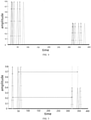
- FIG.4 is a schematic diagram showing part of transmitting times and local lidar echo receiving times after transmission of laser pulses, in the case that the time interval in the lidar transmitting time sequence is injected with the pseudo-random time jitter as shown in FIG.3 .
- the lines in different formats show different times of receiving and transmitting laser pulses. Because transmitting time of the lidar is injected with pseudo-random time jitter, there would also be a corresponding pseudo-random time jitter for the receiving time of the echo of the local lidar.
- FIG. 5 is also a schematic diagram showing part of transmitting times and local lidar echo receiving times after transmission of laser pulses, in the case that the time interval in the lidar transmitting time sequence is injected with the pseudo-random time jitter as shown in FIG.3 .
- the lines in different formats indicate different times of receiving and transmitting laser pulses. It can be seen from FIG.5 that, difference between each laser receiving time and laser transmitting time remain unchanged. As such, regarding transmitting time of the lidar and the echo receiving time of the local lidar, the schematic diagram of the transmitting and receiving effects can be equalized to FIG.2 .
- interference echoes are identified and removed according to correlation between a transmitting time of the local lidar and a receiving time of an echo received by the local lidar.
- the interference echoes removed in this step comprise at least interference echoes of other lidars.
- the interference echoes removed in this step comprise interference echoes of other lidars and a sporadic interference echo of the local lidar.
- an abnormal point detection algorithm may be used to identify the interference echo.
- a removal algorithm may be used to remove the interference echo.
- the step 108 comprises: acquiring a sequence of time differences based on the transmitting time of the local lidar and the receiving time of the received echo, statistically analyzing the time differences to acquire a spatial correlation thereof, and identifying an echo corresponding to an interference time difference whose spatial correlation is lower than a preset value as an interference echo;
- the time difference sequence comprises an inherent time difference between the transmitting time of the local lidar and the receiving time of the local lidar echo, and an interference time difference between the transmitting time of the local lidar and the receiving times of the echoes of other lidars, and even comprises an interference time difference between the transmitting time of the local lidar and the sporadic interference echo time of the local lidar.
- the transmitting time of the local lidar is injected with the pseudo-random time jitter
- the time difference sequence of the transmitting time of the local lidar and the receiving time of the echo of the local lidar is still fixed; however, because the transmitting time of the local lidar is injected with pseudo-random jitter, the distribution of time difference between the transmitting time of the local lidar and the receiving time of the echo of the local lidar is at random.
- the pseudo-random time jitter has disrupted the correlation of the time difference between the transmitting time of the local lidar and the receiving times of the echoes of other lidars.
- the transmitting time of the lidar has jitter, and for the same reason, the receiving time for a corresponding echo of the local lidar also has a corresponding jitter. If an object to be ranged keeps non-moving, the time difference between each group of transmitting time and receiving time of the local lidar will be fixed, and the correlation is high; otherwise, if the time difference between the transmitting time of the local lidar and the receiving times of the echoes of other lidars will be non-fixed, and the correlation between the transmitting time of the local lidar and the receiving times of the echoes of other lidars is disrupted.
- the step 108 comprises: performing ranging on the basis of the transmitting time of the local lidar and the receiving time of echoes received by the local lidar to acquire a ranging sequence, statistically analyzing the ranging sequence to acquire a spatial correlation thereof, identifying an interference ranging sequence whose spatial correlation is lower than a preset value, and identifying an echo corresponding to the interference ranging sequence as an interference echo and removing the interference echo.
- the transmitting time is injected with pseudo-random time jitter, distribution of the time difference between the transmitting time and the receiving times of the echoes of other lidars is at random, the correlation of the interference time difference between the transmitting time of the local lidar and the receiving time of the echo of the other lidar is disrupted, accordingly, the correlation of the interference ranging sequence obtained on the basis of the interference time difference is also disrupted, and thus the obtained ranging sequence also include ranging sequences with a low correlation.
- the present embodiment identifies interference of other lidars on the basis of correlation of time differences.
- N-times Ranging Sequence Result Diagrams as shown in FIG.6 and FIG.7 are respectively acquired by not injected with pseudo-random time jitter and injected with pseudo-random time jitter. It can be seen from FIG. 6 that the time intervals in the sequence of the transmitting time are not injected with pseudo-random time jitter, and the ranging sequences acquired are all correlated, and thus it is difficult to determine which interference ranging sequences are resulted from interference echoes of other lidars.
- the acquired ranging sequences also include ranging sequences with a low correlation.
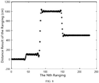
- These ranging sequence with a low correlation include interference ranging sequences resulted from interference echoes of other lidars. Then, these ranging sequence with a low correlation are removed, and a ranging sequence as shown in FIG.8 is acquired.
- the lidar comprises more than two lidars in the same scenario
- the above mentioned modes can let time differences between transmitting time of the local lidar and receiving time of echoes of other lidars be non-fixed, and the correlation of time difference between the transmitting time of the local lidar and the receiving time of the echo of other lidars is disrupted; then, the time difference whose correlation has been disrupted is identified, and the echoes corresponding to the time difference are determined as the interference echoes of other lidars.
- the anti-interference method in the embodiment of the present application further comprises the step of performing laser pulse coding on the lidar to modulate the laser pulse of the lidar, wherein said injecting random time jitter at a transmitting time interval is used to modulate the transmitting time of the lidar after the coding.
- the step of transmitting a laser pulse by the lidar according to the modulated transmitting time is to use a multiple pulses transmitting mechanism to transmit the laser pulse.
- the anti-interference method for the lidar in the embodiment of the present application modulates the transmitting time of the lidar by injecting random time jitter at the time interval in the sequence of the transmitting time, and then let the lidar transmit laser pulses according to the modulated transmitting time.
- the transmitting time and the receiving time of the expected echo are correlated no matter whether the laser transmission pulse of the local lidar is injected with random time jitter or not, but the correlation between the transmitting time of the local lidar and the receiving time of echoes of other lidars may be disrupted by the injection of random time jitter at the transmitting time of the lidar; therefore, in the case where crosstalk occur due to multiple lidars are used in the same scenario, the crosstalk can be counteracted to a certain extent with the above mentioned anti-interference method for the lidar.
- FIG. 9 is a schematic structural diagram of a lidar in an embodiment. Please refer to FIG. 9 , the lidar comprises a controller 910, a transmitting module 920, and a receiving module 930; the controller 910 is respectively connected to the transmitting module 920 and the receiving module 930;
- the controller 910 is configured to modulate a transmitting time of the lidar by injecting random time jitter at a time interval in a sequence of the transmitting time, and cause the transmitting module 920 to transmit laser according to a modulated transmitting time;
- the receiving module 930 is configured to acquire a receiving time of an echo received by the lidar, the echo comprising an expected echo and an unexpected echo of the local lidar, the unexpected echo comprising echoes of other lidars due to crosstalk therewith;
- the controller 910 controller is further configured to identify and remove interference echoes according to correlation between a transmitting time of the local lidar and a receiving time of an echo received by the local lidar.
- the lidar further comprises an analog-to-digital converter 940, and the controller 910 is connected to the receiving module 930 via the analog-to-digital converter 940.
- the receiving module 930 acquires the echo received by the lidar, and transforms the receiving time of the echo into a numerical sequence, and forwards the same to the controller 910.
- the controller 910 comprises a Field Programmable Gate Array (FPGA for short) or an Application Specific Integrated Circuit (ASIC for short).
- the controller 910 further comprises an ARMCPU (Advanced RISC Machines Central Processing Unit, an embedded processor), a PC (personal computer), a DSP (Digital Signal Processing, digital signal processor), or an MCU (Micro controller Unit, micro controller unit).
- ARMCPU Advanced RISC Machines Central Processing Unit, an embedded processor
- PC personal computer
- DSP Digital Signal Processing, digital signal processor
- MCU Micro controller Unit, micro controller unit
- the controller 910 modulates the transmitting time of the lidar by injecting random time jitter at the time interval in the sequence of the transmitting time; and then makes the transmitting module 920 transmit laser pulses according to the modulated transmitting time.
- the transmitting time and the receiving time of the expected echo are correlated no matter whether the laser transmission pulse of the local lidar is injected with random time jitter or not, but the correlation between the transmitting time of the local lidar and the receiving time of echoes of other lidars may be disrupted by the injection of random time jitter at the transmitting time of the lidar; therefore, in the case where crosstalk occur due to multiple lidars are used in the same scenario, the crosstalk can be counteracted to a certain extent with the above mentioned anti-interference method for the lidar.
Landscapes
- Engineering & Computer Science (AREA)
- Physics & Mathematics (AREA)
- Computer Networks & Wireless Communication (AREA)
- General Physics & Mathematics (AREA)
- Radar, Positioning & Navigation (AREA)
- Remote Sensing (AREA)
- Electromagnetism (AREA)
- Optics & Photonics (AREA)
- Optical Radar Systems And Details Thereof (AREA)
Abstract
Description
- The present application claims priority from Chinese Patent Application No.
CN 201910410468.0 filed before the CNIPA on May 17th, 2019 - The present invention relates to the technical field of lidar, in particular to a lidar and an anti-interference method for the lidar.
- Lidar ranging is based mainly on analysis of return time of pulses transmitted from the lidar itself, for example in the case of a pulsed lidar. In order to ensure safety of human eyes and detection efficiency of lidars, a designed pulse is typically a unified single pulse or a finite sequence of encoded pulse. However, when a plurality of lidars are used in the same scenario, especially when they all use a single pulse to transmit laser, all these devices would transmit pulses with similar or even identical profiles, making it difficult to distinguish from each other and easy to cause crosstalk.
- In view of the above, it is necessary to provide a lidar and an anti-interference method therefor.
- An anti-interference method for lidar comprises:
- Modulating a transmitting time of the lidar by injecting random time jitter at a time interval in a sequence of the transmitting time;
- Transmitting a laser pulse by the lidar according to a modulated transmitting time;
- Acquiring a receiving time of an echo received by the lidar, the echo comprising an expected echo and an unexpected echo of the local lidar, the unexpected echo comprising echoes of other lidars due to crosstalk therewith; and
- Identifying and removing interference echoes according to correlation between a transmitting time of the local lidar and a receiving time of an echo received by the local lidar.
- In one of the embodiments, the random time jitter as injected is pseudo-random time jitter.
- In one of the embodiments, the step of modulating a transmitting time of the lidar by injecting random time jitter at a time interval in a sequence of the transmitting time comprises:
- Establishing a transmission timing strategy of the lidar, to determine the transmitting time of the lidar;
- Establishing a pseudo-random jitter strategy of the lidar based on the transmission timing strategy; and
- Modulating the transmitting time of the lidar by injecting pseudo-random time jitter at the time interval in the sequence of the transmitting time of the lidar, so as to re-determine the transmitting time of the lidar.
- In one of the embodiments, the lidar comprises more than two lidars and are all used in the same scenario;
- The step of injecting random time jitter at the time interval in the sequence of the transmitting time is to inject pseudo-random time jitter at time intervals in sequences of transmitting times of each lidar, and the pseudo-random time jitters as injected for each lidar are different.
- In one of the embodiments, the unexpected echoes further comprise echoes received correspondingly when the local lidar transmits laser due to sporadic interference thereof.
- In one of the embodiments, the step of identifying interference echoes according to correlation between a transmitting time of the local lidar and a receiving time of an echo received by the local lidar comprises:
- Performing ranging on the basis of the transmitting time of the local lidar and the receiving time of echoes received by the local lidar; and
- Statistically analyzing a ranging sequence to acquire a spatial correlation thereof, and identifying an interference ranging sequence whose spatial correlation is lower than a preset value and identifying an echo corresponding to the interference ranging sequence as an interference echo.
- In one of the embodiments, it further comprises the step of performing laser pulse coding on the lidar to modulate the laser pulse of the lidar, wherein the injecting random time jitter at a time interval in a sequence of the transmitting time is used to modulate the transmitting time of the lidar after the coding.
- In one of the embodiments, the step of transmitting a laser pulse by the lidar according to a modulated transmitting time is to use a multiple pulses transmitting mechanism to transmit the laser pulse.
- The anti-interference method for the lidar as mentioned above modulates a transmitting time of the lidar by injecting random time jitter at a time interval in a sequence of the transmitting time, and causes the lidar to transmit a laser pulse according to a modulated transmitting time. As such, regarding the case when an echo received by the lidar comprises an expected echo of the local lidar and an unexpected echo from other lidars: because the transmitting time and the expected receiving time of the echo are always in correlation, no matter whether random time jitter is injected or not, and injecting random time jitter in the transmitting time of the lidar may disrupt the correlation between the transmitting time of the local lidar and the transmitting time of other lidars; accordingly, in the case that a plurality of lasers are used together in one scenario and causes crosstalk, the anti-interference method for the lidar above can be used to fight against crosstalk to some extent.
- Also provided is A lidar, wherein the lidar comprises: a controller, a transmitting module and a receiving module; wherein the controller is respectively connected to the transmitting module and the receiving module;
- The controller is configured to modulate a transmitting time of the lidar by injecting random time jitter at a time interval in a sequence of the transmitting time, and cause the transmitting module to transmit a laser pulse according to a modulated transmitting time;
- The receiving module is configured to acquire a receiving time of an echo received by the lidar, the echo comprising an expected echo and an unexpected echo of the local lidar, the unexpected echo comprising echoes of other lidars due to crosstalk therewith; and
- The controller is further configured to identify and remove interference echoes according to correlation between a transmitting time of the local lidar and a receiving time of an echo received by the local lidar.
- In an embodiment, the controller comprises an FPGA or an ASIC.
- The lidar as mentioned above modulates a transmitting time of the lidar by injecting random time jitter at a time interval in a sequence of the transmitting time, and causes the lidar to transmit a laser pulse according to a modulated transmitting time. As such, regarding the case when an echo received by the lidar comprises an expected echo of the local lidar and an unexpected echo from other lidars: because the transmitting time and the expected receiving time of the echo are always in correlation no matter whether random time jitter is injected or not, and injecting random time jitter in the transmitting time of the lidar may disrupt the correlation between the transmitting time of the local lidar and the transmitting time of other lidars; accordingly, in the case that a plurality of lasers are used together in one scenario and causes crosstalk, the lidar above can be used to fight against crosstalk to some extent.
-
-
FIG. 1 is a schematic flowchart of an anti-inference method of lidar in an embodiment; -
FIG. 2 is a schematic diagram of transmitting and receiving effects of a lidar in a specific embodiment; -
FIG. 3 is a schematic diagram of a pseudo-random time jitter sequence generated in a specific embodiment; -
FIG. 4 is a schematic diagram of transmitting and receiving effects of laser pulses after a transmitting time is injected with a pseudo-random time jitter in a specific embodiment; -
FIG. 5 is a schematic diagram of transmitting and receiving effects of laser pulses after a transmitting time is injected with a pseudo-random time jitter in another specific embodiment; -
FIG. 6 is a schematic diagram of ranging effects in the case where a transmitting time interval in a lidar is not injected with a pseudo-random time jitter in a specific embodiment; -
FIG. 7 is a schematic diagram of ranging effects in the case where a transmitting time interval in a lidar is injected with a pseudo-random time jitter in a specific embodiment; -
FIG. 8 is a schematic diagram of ranging effects after ranging sequences with lower correlation are removed in a specific embodiment; -
FIG. 9 is a structural schematic diagram of a lidar in an embodiment; -
FIG. 10 is a structural schematic diagram of a lidar in another embodiment. - In order to make the objectives, technical solutions and advantages of the present invention clear and definite, the present invention will be further described in detail below in conjunction with the accompanying drawings and embodiments. It should be understood that the specific embodiments described herein are only used to explain the present invention, and are not intended to limit the present invention.
- An embodiment of the present application provides an anti-interference method for a lidar. The lidar may be a pulsed lidar, such as a TOF (Time Of Flight) lidar. The following uses injected pseudo-random time jitter as an example to describe the anti-interference method for the lidar in the embodiment of the present application.
FIG. 1 is a schematic flowchart of an anti-inference method for the lidar in an embodiment. Please refer toFIG. 1 , the method comprisessteps 102 to 108: - At
step 102, a transmitting time of the lidar is modulated by injecting random time jitter at a time interval in a sequence of the transmitting time. - As shown in
FIG. 2, FIG. 2 shows a certain transmitting time point of the lidar, and the transmitting time point is the 50th ms. The transmitting time of the lidar can be a time sequence, that is, there are more than two transmitting time points, and the injection of pseudo-random time jitter is to insert time points at each time interval in the sequence of the transmitting time. The corresponding jitter amounts of these inserted time points at the original transmitting time points are defined as the pseudo-random time jitter. Specifically, the transmitting time interval may be fixed. - In one of the embodiments, the
step 102 comprises: establish a transmission timing strategy of the lidar to determine the transmitting time of the lidar; then establish a pseudo-random jitter strategy of the lidar based on the transmission timing strategy; and then modulate the transmitting time of the lidar by injecting pseudo-random time jitter at the time interval in the sequence of the transmitting time of the lidar, so as to re-determine the transmitting time of the lidar. Subsequent lidars transmit lasers according to the transmitting time injected with pseudo-random time jitter, that is, the lidar also transmits lasers at each pseudo-random time point.FIG. 3 is a pseudo-random time jitter strategy established based on the 1st to Nth transmitting times of the lidar in a specific embodiment, and the vertical ordinate indicates the injected pseudo-random time jitter amount, that is, how much time it leads or lags relative to the corresponding transmitting time, where the time unit can be milliseconds. For example, -20 milliseconds indicates that the injected pseudo-random time amount is 20 milliseconds ahead of a certain transmitting time, and 20 milliseconds indicates that the injected pseudo-random time jitter is delayed relative to a certain transmitting time by 20 milliseconds. - For the lidar to perform anti-interference in the embodiment of the present application; there can be more than two lidars provided in the same scenario, that is, each lidar in the same scenario must counteract interference of other lidars. "The same scenario" can specifically refer to more than two lidars located in the same geographic area, or refer to more than two lidars performing ranging on the same object. For different lidars, when establishing a pseudo-random jitter strategy, random jitter patterns therefor are different or seeds for generating random numbers are different, that is, the injected pseudo-random time jitters of different lidar are different. A subsequent step is to make each lidar transmit laser according to the transmitting time injected with a respective pseudo-random time jitter, and can achieve that more than two lidars in the same scenario counteract the interference of multiple lidars at the same time. For example, in the case that there are Device A, Device B and Device C in the same scenario, where Device A counteracts the crosstalk of Device B and Device C, Device B counteracts the crosstalk of Device A and Device C, and Device C counteracts the crosstalk of Device A and Device B. Because the injected pseudo-random time jitter of each device is different, the jitter of the local lidar regarding transmitting time of each device is different from the jitter of the echo times of other lidars, as such, for each device, the correlation of transmitting time of the local lidar and the echo time of other lidars is disrupted. Accordingly, it is possible to make the three lidars counteract interference from multiple lidars simultaneously.
- If the selected seeds are different, the pseudo-random sequence would also be different, therefore, in this embodiment: different seeds can be selected to implement injection of different pseudo-random time jitter. Compared with typical random jitters, a pseudo-random time jitter is easier to achieve different transmitting jitter amounts for different lidars.
- At
step 104, the laser pulses are transmitted by the lidar according to a modulated transmitting time. - In this step, the transmitting time injected with pseudo-random time jitter is the re-determined transmitting time.
- At
step 106, a receiving time of an echo received by the lidar is acquired, the echo comprising an expected echo and an unexpected echo of the local lidar, the unexpected echo comprising echoes of other lidars due to crosstalk therewith. In particular, the unexpected echo may further comprise echoes received correspondingly when the local lidar transmits laser due to sporadic interference thereof. The local lidar is the one that needs to remove the interference echo, for example, where there are Device A, Device B and Device C in the same scenario, the lidar that needs to counteract interference is Device A, then the local lidar is Device A, and the Device B and Device C are other lidars. - For each lidar, the echo receiving time of local lidar is the receiving time corresponding to the laser transmitting time of the local lidar, and the receiving time of echoes of other lidars is the receiving time of the echoes of other lidars received by the local lidar.
- Specifically, the received echoes are all meaningful echoes. Meaningful echoes may be echoes satisfying certain amplitudes or certain pulse widths, and the receiving time of each echo may be the time when each echo peak appears.
- Referring to
FIG.4 , which is a schematic diagram showing part of transmitting times and local lidar echo receiving times after transmission of laser pulses, in the case that the time interval in the lidar transmitting time sequence is injected with the pseudo-random time jitter as shown inFIG.3 . InFig.4 , the lines in different formats show different times of receiving and transmitting laser pulses. Because transmitting time of the lidar is injected with pseudo-random time jitter, there would also be a corresponding pseudo-random time jitter for the receiving time of the echo of the local lidar. As such, the time-difference between the transmitting time of the lidar and the echo receiving time of the local lidar remains unchanged, as compared with the case where the pseudo-random time jitter is not added.FIG. 5 is also a schematic diagram showing part of transmitting times and local lidar echo receiving times after transmission of laser pulses, in the case that the time interval in the lidar transmitting time sequence is injected with the pseudo-random time jitter as shown inFIG.3 . InFIG. 5 , the lines in different formats indicate different times of receiving and transmitting laser pulses. It can be seen fromFIG.5 that, difference between each laser receiving time and laser transmitting time remain unchanged. As such, regarding transmitting time of the lidar and the echo receiving time of the local lidar, the schematic diagram of the transmitting and receiving effects can be equalized toFIG.2 . - At
step 108, interference echoes are identified and removed according to correlation between a transmitting time of the local lidar and a receiving time of an echo received by the local lidar. - The interference echoes removed in this step comprise at least interference echoes of other lidars. For the case where the unexpected echoes further comprise echoes received correspondingly when the local lidar transmits laser due to sporadic interference thereof, the interference echoes removed in this step comprise interference echoes of other lidars and a sporadic interference echo of the local lidar.
- Specifically, an abnormal point detection algorithm may be used to identify the interference echo. Specifically, a removal algorithm may be used to remove the interference echo.
- In one of the embodiments, the
step 108 comprises: acquiring a sequence of time differences based on the transmitting time of the local lidar and the receiving time of the received echo, statistically analyzing the time differences to acquire a spatial correlation thereof, and identifying an echo corresponding to an interference time difference whose spatial correlation is lower than a preset value as an interference echo; the time difference sequence comprises an inherent time difference between the transmitting time of the local lidar and the receiving time of the local lidar echo, and an interference time difference between the transmitting time of the local lidar and the receiving times of the echoes of other lidars, and even comprises an interference time difference between the transmitting time of the local lidar and the sporadic interference echo time of the local lidar. In the present embodiment, although the transmitting time of the local lidar is injected with the pseudo-random time jitter, the time difference sequence of the transmitting time of the local lidar and the receiving time of the echo of the local lidar is still fixed; however, because the transmitting time of the local lidar is injected with pseudo-random jitter, the distribution of time difference between the transmitting time of the local lidar and the receiving time of the echo of the local lidar is at random. As such, the pseudo-random time jitter has disrupted the correlation of the time difference between the transmitting time of the local lidar and the receiving times of the echoes of other lidars. - In this embodiment, the transmitting time of the lidar has jitter, and for the same reason, the receiving time for a corresponding echo of the local lidar also has a corresponding jitter. If an object to be ranged keeps non-moving, the time difference between each group of transmitting time and receiving time of the local lidar will be fixed, and the correlation is high; otherwise, if the time difference between the transmitting time of the local lidar and the receiving times of the echoes of other lidars will be non-fixed, and the correlation between the transmitting time of the local lidar and the receiving times of the echoes of other lidars is disrupted.
- In one of the embodiments, the
step 108 comprises: performing ranging on the basis of the transmitting time of the local lidar and the receiving time of echoes received by the local lidar to acquire a ranging sequence, statistically analyzing the ranging sequence to acquire a spatial correlation thereof, identifying an interference ranging sequence whose spatial correlation is lower than a preset value, and identifying an echo corresponding to the interference ranging sequence as an interference echo and removing the interference echo. In the present embodiment, because the transmitting time is injected with pseudo-random time jitter, distribution of the time difference between the transmitting time and the receiving times of the echoes of other lidars is at random, the correlation of the interference time difference between the transmitting time of the local lidar and the receiving time of the echo of the other lidar is disrupted, accordingly, the correlation of the interference ranging sequence obtained on the basis of the interference time difference is also disrupted, and thus the obtained ranging sequence also include ranging sequences with a low correlation. In essential, the present embodiment identifies interference of other lidars on the basis of correlation of time differences. - N-times Ranging Sequence Result Diagrams as shown in
FIG.6 and FIG.7 are respectively acquired by not injected with pseudo-random time jitter and injected with pseudo-random time jitter. It can be seen fromFIG. 6 that the time intervals in the sequence of the transmitting time are not injected with pseudo-random time jitter, and the ranging sequences acquired are all correlated, and thus it is difficult to determine which interference ranging sequences are resulted from interference echoes of other lidars. InFIG.7 , because the time intervals in the sequence of the transmitting time are injected with the pseudo-random time jitter, the correlation of the time difference between the transmitting time of the local lidar and the receiving time of echoes of other lidars is disrupted, therefore, the acquired ranging sequences also include ranging sequences with a low correlation. These ranging sequence with a low correlation include interference ranging sequences resulted from interference echoes of other lidars. Then, these ranging sequence with a low correlation are removed, and a ranging sequence as shown inFIG.8 is acquired. - In the case that the lidar comprises more than two lidars in the same scenario, if it is aware that only one of the lidars needs anti-interference, then it may be configured that time intervals of the sequences of transmitting times of each lidar are all injected with pseudo-random time jitter and the injected pseudo-random time jitters of each lidar are different. It may also be configured that only time intervals of a sequence of transmitting time of the lidar(s) which needs anti-interference are injected with pseudo-random time jitter, while time-intervals of sequences of transmitting times of other lidars are not injected with pseudo-random time jitter. It may also be configured that only time intervals of a sequence of transmitting time of one lidar are not injected with pseudo-random time jitter, while time-intervals of sequences of transmitting times of other lidars are injected with pseudo-random time jitters, wherein the pseudo-random time jitters injected by other lidars are different. The above mentioned modes can let time differences between transmitting time of the local lidar and receiving time of echoes of other lidars be non-fixed, and the correlation of time difference between the transmitting time of the local lidar and the receiving time of the echo of other lidars is disrupted; then, the time difference whose correlation has been disrupted is identified, and the echoes corresponding to the time difference are determined as the interference echoes of other lidars.
- Traditional interference countermeasure strategies for multiple lidars adopt pulse code transmitting strategy or multiple pulses transmitting strategy. Regarding the pulse code transmitting strategy, however, due to hardware limitation of the lidar itself, it cannot guarantee that pulse code transmitted laser reach a light output threshold, and light output efficiency and ranging efficiency of the lidar might be reduced. Regarding the multiple pulses transmitting strategy, it takes more time to transmit and would reduce ranging efficiency, and the lidar is required to have a high performance. By contrast, the anti-interference method of the embodiments of the present invention uses pseudo-random time jitter to fight against interference, has no conflict with the transmission mechanisms such as laser pulse coding and multiple pulse transmitting, and it is even possible to use along with laser pulse coding or multiple pulse transmitting to fight against interference. In the following, embodiments that are used along with laser pulse coding or with multiple pulse transmitting mechanisms to fight against interference will be described.
- In one of the embodiments, the anti-interference method in the embodiment of the present application further comprises the step of performing laser pulse coding on the lidar to modulate the laser pulse of the lidar, wherein said injecting random time jitter at a transmitting time interval is used to modulate the transmitting time of the lidar after the coding. In another embodiment, in the anti-interference method in the embodiment of the present application, the step of transmitting a laser pulse by the lidar according to the modulated transmitting time is to use a multiple pulses transmitting mechanism to transmit the laser pulse.
- In these two embodiments, when injection of the pseudo-random jitter into the transmitting time is adopted and laser pulse coding or multiple pulse transmitting mechanisms are used at the same time to fight against interference, although the detection accuracy and detection efficiency of the lidar are compromised to a certain extent, the anti-interference performance of the lidar can be further improved.
- In conclusion, the anti-interference method for the lidar in the embodiment of the present application modulates the transmitting time of the lidar by injecting random time jitter at the time interval in the sequence of the transmitting time, and then let the lidar transmit laser pulses according to the modulated transmitting time. As such, in the case that the echo received by the lidar comprise the expected echo of the local lidar and the unexpected echo of other lidar, the transmitting time and the receiving time of the expected echo are correlated no matter whether the laser transmission pulse of the local lidar is injected with random time jitter or not, but the correlation between the transmitting time of the local lidar and the receiving time of echoes of other lidars may be disrupted by the injection of random time jitter at the transmitting time of the lidar; therefore, in the case where crosstalk occur due to multiple lidars are used in the same scenario, the crosstalk can be counteracted to a certain extent with the above mentioned anti-interference method for the lidar.
- An embodiment of the present application also proposes a lidar. The lidar may be a pulsed lidar, such as a TOF (Time Of Flight) lidar.
FIG. 9 is a schematic structural diagram of a lidar in an embodiment. Please refer toFIG. 9 , the lidar comprises acontroller 910, a transmittingmodule 920, and areceiving module 930; thecontroller 910 is respectively connected to thetransmitting module 920 and the receivingmodule 930; - The
controller 910 is configured to modulate a transmitting time of the lidar by injecting random time jitter at a time interval in a sequence of the transmitting time, and cause thetransmitting module 920 to transmit laser according to a modulated transmitting time; - The receiving
module 930 is configured to acquire a receiving time of an echo received by the lidar, the echo comprising an expected echo and an unexpected echo of the local lidar, the unexpected echo comprising echoes of other lidars due to crosstalk therewith; and - The
controller 910 controller is further configured to identify and remove interference echoes according to correlation between a transmitting time of the local lidar and a receiving time of an echo received by the local lidar. - Specifically, please refer to
FIG. 10 , the lidar further comprises an analog-to-digital converter 940, and thecontroller 910 is connected to the receivingmodule 930 via the analog-to-digital converter 940. The receivingmodule 930 acquires the echo received by the lidar, and transforms the receiving time of the echo into a numerical sequence, and forwards the same to thecontroller 910. - Specifically, the
controller 910 comprises a Field Programmable Gate Array (FPGA for short) or an Application Specific Integrated Circuit (ASIC for short). In other embodiments, thecontroller 910 further comprises an ARMCPU (Advanced RISC Machines Central Processing Unit, an embedded processor), a PC (personal computer), a DSP (Digital Signal Processing, digital signal processor), or an MCU (Micro controller Unit, micro controller unit). - For the lidar in the embodiment of the present application, the
controller 910 modulates the transmitting time of the lidar by injecting random time jitter at the time interval in the sequence of the transmitting time; and then makes the transmittingmodule 920 transmit laser pulses according to the modulated transmitting time. As such, in the case that the echo received by the lidar comprise the expected echo of the local lidar and the unexpected echo of other lidar, the transmitting time and the receiving time of the expected echo are correlated no matter whether the laser transmission pulse of the local lidar is injected with random time jitter or not, but the correlation between the transmitting time of the local lidar and the receiving time of echoes of other lidars may be disrupted by the injection of random time jitter at the transmitting time of the lidar; therefore, in the case where crosstalk occur due to multiple lidars are used in the same scenario, the crosstalk can be counteracted to a certain extent with the above mentioned anti-interference method for the lidar. - The technical features of the above-mentioned embodiments can be arbitrarily combined. For simplicity of the description, not all possible combinations of the technical features in the above-mentioned embodiments are described. However, as long as there is no contradiction in the combinations of these technical features, all of them should be considered as within the scope of this description.
- Although only a few implementations of the present invention are described in the embodiments above in a specific and detailed way, they are not to be construed as limiting the patent scope of the invention. It should be noted that, those of ordinary skill in the art can also make several modifications and improvements without departing from the concept of the present invention, which all fall within the protection scope of the present invention. Therefore, the protection scope of the invention patent shall be subject to the appended claims.
Claims (10)
- An anti-interference method for a lidar, comprising:modulating a transmitting time of the lidar by injecting a random time jitter at a time interval in a transmitting time sequence;transmitting a laser pulse by the lidar according to a modulated transmitting time;acquiring a receiving time of an echo received by the lidar, the echo comprising an expected echo and an unexpected echo of a local lidar, the unexpected echo comprising echoes of other lidars due to crosstalks; andidentifying and removing interference echoes according to a correlation between a transmitting time of the local lidar and a receiving time of an echo received by the local lidar.
- The method of claim 1, wherein the random time jitter as injected is pseudo-random time jitter.
- The method of claim 1, wherein the step of modulating a transmitting time of the lidar by injecting a random time jitter at a time interval in a transmitting time sequence comprises:establishing a transmission timing strategy of the lidar to determine the transmitting time of the lidar;establishing a pseudo-random jitter strategy of the lidar based on the transmission timing strategy; andmodulating the transmitting time of the lidar by injecting a pseudo-random time jitter at the time interval in the transmitting time sequence of the lidar, so as to re-determine the transmitting time of the lidar.
- The method of claim 1, wherein a lidar assembly comprises more than two lidars all used in the same scenario, and the step of injecting the random time jitter at the time interval in the transmitting time sequence comprises injecting a pseudo-random time jitter at a time interval in the transmitting time sequence of each lidar, the pseudo-random time jitters as injected for the lidars being different from one another.
- The method of claim 2, wherein the unexpected echoes further comprise echoes received correspondingly when the local lidar transmits laser due to sporadic interference thereof.
- The method of any one of claims 1 to 5, wherein the step of identifying interference echoes according to a correlation between a transmitting time of the local lidar and a receiving time of an echo received by the local lidar comprises:performing ranging on the basis of the transmitting time of the local lidar and the receiving time of echoes received by the local lidar; andstatistically analyzing a ranging sequence to acquire a spatial correlation thereof, identifying an interference ranging sequence whose spatial correlation is lower than a preset value, and identifying an echo corresponding to the interference ranging sequence as an interference echo.
- The method of claim 6, further comprising performing laser pulse coding on the lidar to modulate the laser pulse of the lidar, wherein the step of injecting a random time jitter at a time interval in a transmitting time sequence is performed to modulate the transmitting time of the lidar after the coding.
- The method of claim 6, wherein the step of transmitting a laser pulse by the lidar according to a modulated transmitting time comprises using a multiple-pulse transmitting mechanism to transmit the laser pulse.
- A lidar, comprising: a transmitting module, a receiving module, and a controller respectively connected to the transmitting module and the receiving module, wherein:the controller is configured to modulate a transmitting time of the lidar by injecting a random time jitter at a time interval in a transmitting time sequence and cause the transmitting module to transmit a laser pulse according to a modulated transmitting time;the receiving module is configured to acquire a receiving time of an echo received by the lidar, the echo comprising an expected echo and an unexpected echo of the local lidar, the unexpected echo comprising echoes of other lidars due to crosstalks; andthe controller is further configured to identify and remove interference echoes according to a correlation between a transmitting time of the local lidar and a receiving time of an echo received by the local lidar.
- The lidar of claim 9, wherein the controller comprises a Field Programmable Gate Array, FPGA, or an Application Specific Integrated Circuit, ASIC.
Applications Claiming Priority (2)
| Application Number | Priority Date | Filing Date | Title |
|---|---|---|---|
| CN201910410468.0A CN110208814B (en) | 2019-05-17 | 2019-05-17 | Laser radar and anti-interference method thereof |
| PCT/CN2020/089140 WO2020233415A1 (en) | 2019-05-17 | 2020-05-08 | Laser radar, and anti-jamming method therefor |
Publications (4)
| Publication Number | Publication Date |
|---|---|
| EP3964867A1 true EP3964867A1 (en) | 2022-03-09 |
| EP3964867A4 EP3964867A4 (en) | 2022-06-22 |
| EP3964867B1 EP3964867B1 (en) | 2026-01-28 |
| EP3964867C0 EP3964867C0 (en) | 2026-01-28 |
Family
ID=67787381
Family Applications (1)
| Application Number | Title | Priority Date | Filing Date |
|---|---|---|---|
| EP20809106.6A Active EP3964867B1 (en) | 2019-05-17 | 2020-05-08 | Laser radar, and anti-jamming method therefor |
Country Status (4)
| Country | Link |
|---|---|
| US (1) | US12265178B2 (en) |
| EP (1) | EP3964867B1 (en) |
| CN (1) | CN110208814B (en) |
| WO (1) | WO2020233415A1 (en) |
Families Citing this family (27)
| Publication number | Priority date | Publication date | Assignee | Title |
|---|---|---|---|---|
| CN110208814B (en) * | 2019-05-17 | 2022-07-08 | 深圳市速腾聚创科技有限公司 | Laser radar and anti-interference method thereof |
| CN110609267B (en) * | 2019-09-19 | 2022-07-08 | 深圳奥锐达科技有限公司 | Laser radar system and anti-interference method thereof |
| CN110764097B (en) * | 2019-11-14 | 2023-03-21 | 深圳市镭神智能系统有限公司 | Anti-interference method and device for laser radar, laser radar and storage medium |
| CN110780306B (en) * | 2019-11-19 | 2023-03-21 | 深圳市镭神智能系统有限公司 | Anti-interference method for laser radar and laser radar |
| CN111837053B (en) | 2020-03-25 | 2024-04-26 | 深圳市汇顶科技股份有限公司 | Distance measurement method and distance measurement system based on time of flight |
| CN114391112A (en) * | 2020-08-21 | 2022-04-22 | 深圳市大疆创新科技有限公司 | Laser ranging method, ranging device and movable platform |
| CN112711004B (en) * | 2020-12-18 | 2022-12-02 | 上海星秒光电科技有限公司 | Anti-interference method and device for laser ranging, laser ranging equipment and readable storage medium |
| CN112904312B (en) * | 2021-01-25 | 2024-01-30 | 深圳煜炜光学科技有限公司 | Anti-interference method and device for laser radar |
| WO2022213659A1 (en) * | 2021-04-07 | 2022-10-13 | 上海禾赛科技有限公司 | Laser radar and distance measuring method |
| CN115166760A (en) * | 2021-04-07 | 2022-10-11 | 上海禾赛科技有限公司 | Laser radar and ranging method |
| CN115248427A (en) * | 2021-04-27 | 2022-10-28 | 上海禾赛科技有限公司 | Laser radar control method and laser radar |
| CN114924256A (en) * | 2021-04-29 | 2022-08-19 | 深圳阜时科技有限公司 | Optical sensing device, electronic device and interference suppression method of optical sensing device |
| CN114942423B (en) * | 2021-04-29 | 2026-05-01 | 阜时科技有限公司 | Optical sensing device and interference suppression method thereof |
| CN121878649A (en) * | 2021-06-30 | 2026-04-17 | 深圳市速腾聚创科技有限公司 | Signal processing method and device and terminal equipment |
| CN117730264A (en) * | 2021-07-28 | 2024-03-19 | 深圳市速腾聚创科技有限公司 | Lidar anti-interference method, device, readable storage medium and terminal equipment |
| CN113805191A (en) * | 2021-09-16 | 2021-12-17 | 梁平 | Laser radar multi-machine crosstalk prevention method and device and storage medium |
| CN114089358B (en) * | 2021-11-04 | 2026-02-17 | 深圳市灵明光子科技有限公司 | Distance calculating method, distance measuring system and storage medium |
| CN113759340B (en) * | 2021-11-10 | 2022-02-18 | 北京一径科技有限公司 | Echo signal processing method and device, laser radar and storage medium |
| CN115825930B (en) * | 2021-12-31 | 2023-12-12 | 深圳市速腾聚创科技有限公司 | Laser radar anti-interference method and device, storage medium and laser radar |
| CN116338649B (en) * | 2021-12-23 | 2024-11-05 | 深圳市速腾聚创科技有限公司 | Laser radar anti-interference method, laser radar anti-interference device and electronic equipment |
| CN114814789B (en) * | 2022-04-13 | 2025-08-01 | 浙江大学 | Pulse control signal design method based on laser radar target point cloud |
| CN117434539B (en) * | 2022-07-15 | 2025-08-15 | 深圳市速腾聚创科技有限公司 | Control method, device and computer readable storage medium for multichannel laser emission |
| CN115079145B (en) * | 2022-08-18 | 2022-11-11 | 深圳煜炜光学科技有限公司 | Method and device for improving anti-interference capability of laser radar |
| CN118731912B (en) * | 2023-03-31 | 2025-03-28 | 深圳市镭神智能系统有限公司 | Laser radar anti-interference method, device, laser radar and readable storage medium |
| CN117169845B (en) * | 2023-09-06 | 2026-07-17 | 厦门新诺电子有限公司 | Single-pulse radar echo signal processing method, device and storage medium |
| KR20260102067A (en) * | 2024-12-24 | 2026-07-01 | 엘지이노텍 주식회사 | Depth information generating apparatus and depth information generating method of the same |
| CN119581983A (en) * | 2025-02-07 | 2025-03-07 | 长春理工大学 | A fast-start random jitter delay laser emission device and output method |
Family Cites Families (27)
| Publication number | Priority date | Publication date | Assignee | Title |
|---|---|---|---|---|
| US5075863A (en) * | 1988-02-09 | 1991-12-24 | Nkk Corporation | Distance measuring method and apparatus therefor |
| US5790475A (en) * | 1996-10-28 | 1998-08-04 | Multispec Corporation | Process and apparatus for improved interference suppression in echo-location and imaging systems |
| US6522644B2 (en) * | 1998-06-25 | 2003-02-18 | Telefonaktiebolaget Lm Ericsson (Publ) | Method for decorrelating background interference in a time-synchronized mobile communications system |
| JP3899708B2 (en) * | 1998-10-16 | 2007-03-28 | 株式会社デンソー | Distance measuring device |
| JP2005017143A (en) * | 2003-06-26 | 2005-01-20 | Toshiba Corp | Weather radar signal processor |
| CN101236253B (en) * | 2008-03-07 | 2010-07-07 | 中国科学院上海光学精密机械研究所 | High-precision speed and distance measuring laser radar system and speed and distance measuring method |
| CN103926590B (en) * | 2014-04-01 | 2016-03-30 | 中国科学院合肥物质科学研究院 | A kind of laser multiple-pulse distance-finding method of unequal-interval and distance measuring equipment thereof |
| CN104457452A (en) * | 2014-10-20 | 2015-03-25 | 上海电机学院 | Pseudo-random code system-based laser fuze system and target identification method thereof |
| US10215847B2 (en) * | 2015-05-07 | 2019-02-26 | GM Global Technology Operations LLC | Pseudo random sequences in array lidar systems |
| CN104931973B (en) * | 2015-06-17 | 2017-05-10 | 浙江理工大学 | Asymmetric phase encoding ranging method applied to laser radar system |
| US10908287B2 (en) * | 2016-05-10 | 2021-02-02 | Texas Instruments Incorporated | Methods and apparatus for LIDAR operation with narrowband intensity modulation |
| US20180059220A1 (en) * | 2016-08-30 | 2018-03-01 | Qualcomm Incorporated | Laser ranging device with beam signature and signature recognition |
| US20180081041A1 (en) * | 2016-09-22 | 2018-03-22 | Apple Inc. | LiDAR with irregular pulse sequence |
| JP7177065B2 (en) * | 2017-01-05 | 2022-11-22 | イノビュージョン インコーポレイテッド | Methods and systems for encoding and decoding lidar |
| CN107300705B (en) * | 2017-06-11 | 2020-04-03 | 宁波飞芯电子科技有限公司 | Lidar ranging system and ranging method based on carrier modulation |
| US10754033B2 (en) * | 2017-06-30 | 2020-08-25 | Waymo Llc | Light detection and ranging (LIDAR) device range aliasing resilience by multiple hypotheses |
| JP6860459B2 (en) * | 2017-09-19 | 2021-04-14 | 株式会社東芝 | Distance measuring device |
| CN107728156B (en) * | 2017-09-29 | 2019-11-22 | 西安知微传感技术有限公司 | A kind of method and system enhancing laser radar anti-interference |
| CN109683171A (en) * | 2017-10-19 | 2019-04-26 | 上海禾赛光电科技有限公司 | Laser radar and its distance measuring method |
| CN108717182B (en) * | 2018-05-02 | 2023-10-31 | 深圳市速腾聚创科技有限公司 | Anti-interference method of laser radar and anti-interference laser radar |
| CN108519604B (en) * | 2018-03-08 | 2021-08-10 | 北京理工大学 | Solid-state area array laser radar ranging method based on pseudo-random code modulation and demodulation |
| CN108919281A (en) * | 2018-04-10 | 2018-11-30 | 中国科学院上海技术物理研究所 | Quantum laser radar based on wavelength time quantum state random interleaving light pulse sequence |
| CN109116331B (en) * | 2018-06-27 | 2020-04-24 | 上海禾赛光电科技有限公司 | Coding laser transceiver, distance measuring device and laser radar system |
| CN109164454B (en) * | 2018-08-23 | 2020-10-30 | 武汉大学 | Pseudo-random code modulation-based medium-long range high-frequency laser radar ranging ambiguity solving method |
| CN109490851B (en) * | 2018-11-27 | 2021-05-28 | 重庆秦嵩科技有限公司 | Anti-interference method based on inter-pulse pseudo-random code |
| JP7541030B2 (en) * | 2019-05-01 | 2024-08-27 | アウスター インコーポレイテッド | Temporal Jitter in LIDAR Systems |
| CN110208814B (en) * | 2019-05-17 | 2022-07-08 | 深圳市速腾聚创科技有限公司 | Laser radar and anti-interference method thereof |
-
2019
- 2019-05-17 CN CN201910410468.0A patent/CN110208814B/en active Active
-
2020
- 2020-05-08 EP EP20809106.6A patent/EP3964867B1/en active Active
- 2020-05-08 WO PCT/CN2020/089140 patent/WO2020233415A1/en not_active Ceased
- 2020-11-13 US US17/098,233 patent/US12265178B2/en active Active
Also Published As
| Publication number | Publication date |
|---|---|
| CN110208814A (en) | 2019-09-06 |
| EP3964867A4 (en) | 2022-06-22 |
| US12265178B2 (en) | 2025-04-01 |
| US20210063538A1 (en) | 2021-03-04 |
| CN110208814B (en) | 2022-07-08 |
| EP3964867B1 (en) | 2026-01-28 |
| WO2020233415A1 (en) | 2020-11-26 |
| EP3964867C0 (en) | 2026-01-28 |
Similar Documents
| Publication | Publication Date | Title |
|---|---|---|
| US12265178B2 (en) | Lidar and anti-interference method therefor | |
| US11947047B2 (en) | Method and system for encoding and decoding LiDAR | |
| CN103675793B (en) | The countercheck of Active laser interference | |
| US5719579A (en) | Virtual noise radar waveform for reduced radar detectability | |
| US20130116971A1 (en) | Method for generating a signal for a distance measurement and method and system for distance measurement between a transmitter and a receiver | |
| CN110361715A (en) | A pulse coding device, coding method and lidar system | |
| CN112596042B (en) | Laser radar device and method for eliminating crosstalk | |
| CN112929157B (en) | Quantum key distribution device, method and system | |
| EP4276491A1 (en) | Anti-interference method and device for lidar | |
| MX2021003066A (en) | Improving return signal detection in a light ranging and detection system with pulse encoding. | |
| US20210080544A1 (en) | Operating method and control unit for a lidar system, lidar system, and working device | |
| US20060020857A1 (en) | Disable/enable control for laser driver eye safety | |
| CN112881984B (en) | A radar signal anti-interference processing method, device and storage medium | |
| CN113759340B (en) | Echo signal processing method and device, laser radar and storage medium | |
| Tsay et al. | Generations of chaos-modulated pulses based on a gain-switched semiconductor laser subject to delay-synchronized optical feedback for pulsed chaos lidar applications | |
| CN114325658A (en) | Laser radar interference resisting method, device, equipment and storage medium | |
| Ma et al. | Comparison of jamming methods for underwater acoustic DSSS communication systems | |
| CN110764097A (en) | Anti-interference method and device for laser radar, laser radar and storage medium | |
| CN116743369A (en) | Quantum key distribution method, sender, receiver and quantum key distribution system | |
| EP3869230B1 (en) | Distance measurement device and distance measurement method | |
| CN116973927A (en) | Laser ranging and laser coding modulation methods, systems, devices and electronic equipment | |
| RU2525749C2 (en) | Method of preventing message transmission delay when resolving access conflicts and system therefor | |
| Chen et al. | Novel multipulses technology for pulse laser radar | |
| RU2491570C1 (en) | Quadrature pulsed noise compensator | |
| US12379457B2 (en) | Radar system and a radar method for replay resistant radar operations |
Legal Events
| Date | Code | Title | Description |
|---|---|---|---|
| STAA | Information on the status of an ep patent application or granted ep patent |
Free format text: STATUS: THE INTERNATIONAL PUBLICATION HAS BEEN MADE |
|
| PUAI | Public reference made under article 153(3) epc to a published international application that has entered the european phase |
Free format text: ORIGINAL CODE: 0009012 |
|
| STAA | Information on the status of an ep patent application or granted ep patent |
Free format text: STATUS: REQUEST FOR EXAMINATION WAS MADE |
|
| 17P | Request for examination filed |
Effective date: 20211201 |
|
| AK | Designated contracting states |
Kind code of ref document: A1 Designated state(s): AL AT BE BG CH CY CZ DE DK EE ES FI FR GB GR HR HU IE IS IT LI LT LU LV MC MK MT NL NO PL PT RO RS SE SI SK SM TR |
|
| RAP3 | Party data changed (applicant data changed or rights of an application transferred) |
Owner name: SUTENG INNOVATION TECHNOLOGY CO., LTD. |
|
| A4 | Supplementary search report drawn up and despatched |
Effective date: 20220520 |
|
| RIC1 | Information provided on ipc code assigned before grant |
Ipc: G01S 7/48 20060101ALI20220516BHEP Ipc: G01S 7/487 20060101ALI20220516BHEP Ipc: G01S 17/14 20200101ALI20220516BHEP Ipc: G01S 17/08 20060101AFI20220516BHEP |
|
| DAV | Request for validation of the european patent (deleted) | ||
| DAX | Request for extension of the european patent (deleted) | ||
| GRAP | Despatch of communication of intention to grant a patent |
Free format text: ORIGINAL CODE: EPIDOSNIGR1 |
|
| STAA | Information on the status of an ep patent application or granted ep patent |
Free format text: STATUS: GRANT OF PATENT IS INTENDED |
|
| INTG | Intention to grant announced |
Effective date: 20250822 |
|
| GRAS | Grant fee paid |
Free format text: ORIGINAL CODE: EPIDOSNIGR3 |
|
| GRAA | (expected) grant |
Free format text: ORIGINAL CODE: 0009210 |
|
| STAA | Information on the status of an ep patent application or granted ep patent |
Free format text: STATUS: THE PATENT HAS BEEN GRANTED |
|
| AK | Designated contracting states |
Kind code of ref document: B1 Designated state(s): AL AT BE BG CH CY CZ DE DK EE ES FI FR GB GR HR HU IE IS IT LI LT LU LV MC MK MT NL NO PL PT RO RS SE SI SK SM TR |
|
| REG | Reference to a national code |
Ref country code: CH Ref legal event code: F10 Free format text: ST27 STATUS EVENT CODE: U-0-0-F10-F00 (AS PROVIDED BY THE NATIONAL OFFICE) Effective date: 20260128 Ref country code: GB Ref legal event code: FG4D |
|
| REG | Reference to a national code |
Ref country code: DE Ref legal event code: R096 Ref document number: 602020066092 Country of ref document: DE |
|
| REG | Reference to a national code |
Ref country code: IE Ref legal event code: FG4D |
|
| U01 | Request for unitary effect filed |
Effective date: 20260218 |
|
| U07 | Unitary effect registered |
Designated state(s): AT BE BG DE DK EE FI FR IT LT LU LV MT NL PT RO SE SI Effective date: 20260223 |
|
| U20 | Renewal fee for the european patent with unitary effect paid |
Year of fee payment: 7 Effective date: 20260428 |
|
| PG25 | Lapsed in a contracting state [announced via postgrant information from national office to epo] |
Ref country code: RS Free format text: LAPSE BECAUSE OF FAILURE TO SUBMIT A TRANSLATION OF THE DESCRIPTION OR TO PAY THE FEE WITHIN THE PRESCRIBED TIME-LIMIT Effective date: 20260428 |
|
| PG25 | Lapsed in a contracting state [announced via postgrant information from national office to epo] |
Ref country code: ES Free format text: LAPSE BECAUSE OF FAILURE TO SUBMIT A TRANSLATION OF THE DESCRIPTION OR TO PAY THE FEE WITHIN THE PRESCRIBED TIME-LIMIT Effective date: 20260128 |
|
| PG25 | Lapsed in a contracting state [announced via postgrant information from national office to epo] |
Ref country code: PL Free format text: LAPSE BECAUSE OF FAILURE TO SUBMIT A TRANSLATION OF THE DESCRIPTION OR TO PAY THE FEE WITHIN THE PRESCRIBED TIME-LIMIT Effective date: 20260128 |
|
| PG25 | Lapsed in a contracting state [announced via postgrant information from national office to epo] |
Ref country code: GR Free format text: LAPSE BECAUSE OF FAILURE TO SUBMIT A TRANSLATION OF THE DESCRIPTION OR TO PAY THE FEE WITHIN THE PRESCRIBED TIME-LIMIT Effective date: 20260429 |
|
| PG25 | Lapsed in a contracting state [announced via postgrant information from national office to epo] |
Ref country code: NO Free format text: LAPSE BECAUSE OF FAILURE TO SUBMIT A TRANSLATION OF THE DESCRIPTION OR TO PAY THE FEE WITHIN THE PRESCRIBED TIME-LIMIT Effective date: 20260428 |
|
| PG25 | Lapsed in a contracting state [announced via postgrant information from national office to epo] |
Ref country code: HR Free format text: LAPSE BECAUSE OF FAILURE TO SUBMIT A TRANSLATION OF THE DESCRIPTION OR TO PAY THE FEE WITHIN THE PRESCRIBED TIME-LIMIT Effective date: 20260128 |
|
| PG25 | Lapsed in a contracting state [announced via postgrant information from national office to epo] |
Ref country code: IS Free format text: LAPSE BECAUSE OF FAILURE TO SUBMIT A TRANSLATION OF THE DESCRIPTION OR TO PAY THE FEE WITHIN THE PRESCRIBED TIME-LIMIT Effective date: 20260528 |