EP3964848A1 - Contact arrangement having a measuring device for determining a contacting state of the contact arrangement by means of an acoustic signal - Google Patents
Contact arrangement having a measuring device for determining a contacting state of the contact arrangement by means of an acoustic signal Download PDFInfo
- Publication number
- EP3964848A1 EP3964848A1 EP21192378.4A EP21192378A EP3964848A1 EP 3964848 A1 EP3964848 A1 EP 3964848A1 EP 21192378 A EP21192378 A EP 21192378A EP 3964848 A1 EP3964848 A1 EP 3964848A1
- Authority
- EP
- European Patent Office
- Prior art keywords
- contact
- contacts
- signal
- acoustic signal
- contact arrangement
- Prior art date
- Legal status (The legal status is an assumption and is not a legal conclusion. Google has not performed a legal analysis and makes no representation as to the accuracy of the status listed.)
- Granted
Links
Images
Classifications
-
- G—PHYSICS
- G01—MEASURING; TESTING
- G01R—MEASURING ELECTRIC VARIABLES; MEASURING MAGNETIC VARIABLES
- G01R31/00—Arrangements for testing electric properties; Arrangements for locating electric faults; Arrangements for electrical testing characterised by what is being tested not provided for elsewhere
- G01R31/327—Testing of circuit interrupters, switches or circuit-breakers
- G01R31/3271—Testing of circuit interrupters, switches or circuit-breakers of high voltage or medium voltage devices
- G01R31/3272—Apparatus, systems or circuits therefor
- G01R31/3274—Details related to measuring, e.g. sensing, displaying or computing; Measuring of variables related to the contact pieces, e.g. wear, position or resistance
-
- G—PHYSICS
- G01—MEASURING; TESTING
- G01R—MEASURING ELECTRIC VARIABLES; MEASURING MAGNETIC VARIABLES
- G01R31/00—Arrangements for testing electric properties; Arrangements for locating electric faults; Arrangements for electrical testing characterised by what is being tested not provided for elsewhere
- G01R31/50—Testing of electric apparatus, lines, cables or components for short-circuits, continuity, leakage current or incorrect line connections
- G01R31/66—Testing of connections, e.g. of plugs or non-disconnectable joints
-
- G—PHYSICS
- G01—MEASURING; TESTING
- G01R—MEASURING ELECTRIC VARIABLES; MEASURING MAGNETIC VARIABLES
- G01R1/00—Details of instruments or arrangements of the types included in groups G01R5/00 - G01R13/00 and G01R31/00
- G01R1/02—General constructional details
- G01R1/06—Measuring leads; Measuring probes
- G01R1/067—Measuring probes
- G01R1/073—Multiple probes
-
- G—PHYSICS
- G01—MEASURING; TESTING
- G01H—MEASUREMENT OF MECHANICAL VIBRATIONS OR ULTRASONIC, SONIC OR INFRASONIC WAVES
- G01H11/00—Measuring mechanical vibrations or ultrasonic, sonic or infrasonic waves by detecting changes in electric or magnetic properties
- G01H11/06—Measuring mechanical vibrations or ultrasonic, sonic or infrasonic waves by detecting changes in electric or magnetic properties by electric means
- G01H11/08—Measuring mechanical vibrations or ultrasonic, sonic or infrasonic waves by detecting changes in electric or magnetic properties by electric means using piezoelectric devices
-
- G—PHYSICS
- G01—MEASURING; TESTING
- G01R—MEASURING ELECTRIC VARIABLES; MEASURING MAGNETIC VARIABLES
- G01R1/00—Details of instruments or arrangements of the types included in groups G01R5/00 - G01R13/00 and G01R31/00
- G01R1/02—General constructional details
- G01R1/04—Housings; Supporting members; Arrangements of terminals
- G01R1/0408—Test fixtures or contact fields; Connectors or connecting adaptors; Test clips; Test sockets
-
- G—PHYSICS
- G08—SIGNALLING
- G08C—TRANSMISSION SYSTEMS FOR MEASURED VALUES, CONTROL OR SIMILAR SIGNALS
- G08C19/00—Electric signal transmission systems
- G08C19/16—Electric signal transmission systems in which transmission is by pulses
-
- G—PHYSICS
- G08—SIGNALLING
- G08C—TRANSMISSION SYSTEMS FOR MEASURED VALUES, CONTROL OR SIMILAR SIGNALS
- G08C23/00—Non-electrical signal transmission systems, e.g. optical systems
- G08C23/02—Non-electrical signal transmission systems, e.g. optical systems using infrasonic, sonic or ultrasonic waves
-
- H—ELECTRICITY
- H01—ELECTRIC ELEMENTS
- H01R—ELECTRICALLY-CONDUCTIVE CONNECTIONS; STRUCTURAL ASSOCIATIONS OF A PLURALITY OF MUTUALLY-INSULATED ELECTRICAL CONNECTING ELEMENTS; COUPLING DEVICES; CURRENT COLLECTORS
- H01R13/00—Details of coupling devices of the kinds covered by groups H01R12/70 or H01R24/00 - H01R33/00
- H01R13/66—Structural association with built-in electrical component
- H01R13/665—Structural association with built-in electrical component with built-in electronic circuit
- H01R13/6683—Structural association with built-in electrical component with built-in electronic circuit with built-in sensor
Definitions
- the invention relates to a contact arrangement having a measuring device and to a method for measuring a contacting state, in particular a contact arrangement for the high-voltage and/or high-current range.
- Such contact arrangements have two contacts which are electrically conductively connected to each other in a closed position and electrically isolated from each other in an isolated position.
- the contact arrangements can comprise a detector which allows to determine whether the contacts are isolated or closed. In this case, the contacting state is only measured indirectly via the position of an actuating element. However, this means that a state of failure in which, for example, one of the contacts is welded to the contact bridge cannot be detected or falsely declared as open or closed. Consequently, such contact arrangements are unsafe. Detectors registering changes in the electric and/or magnetic field are mostly also dependent on the level and type of the switched voltage and therefore cannot be used arbitrarily for different contact arrangements.
- the object of the invention is to provide a solution which can detect the contacting state of two contacts more reliably and in a versatile manner.
- a contact arrangement having a measuring device for detecting a contacting state of the contact arrangement and having at least two electrical contacts which are electrically isolated from one another in a first, open, contacting state and are electrically connected to one another in a second, closed, contacting state.
- the measuring device comprises an acoustic signal generator, which is adapted to couple an acoustic signal, in particular a sound wave, into a first of the at least two contacts, and a signal receiver, which is connected to a second of the at least two contacts in a sound-conducting manner.
- this is solved by coupling an acoustic signal into a first contact of the at least two contacts and receiving the acoustic signal at a second contact of the at least two contacts.
- the invention further relates to a computer-implemented method comprising, according to the invention, the following steps:
- the acoustic signal is conducted by means of structure-borne sound via the contacts of the contact arrangement from the signal transmitter to the signal receiver. Because the signal transmitter couples the acoustic signal into one contact and the signal receiver receives the signal at another contact, a measurement based on transmission takes place. In contrast to an indirect measurement based on reflection, in which the signal transmitter and signal receiver are arranged on the same contact and the reflection of the acoustic signal is registered on an actuating element, a higher level of safety is ensured.
- the acoustic signal in contrast to a magnetic or electrical signal, is independent of the type and level of voltage, failures caused, for example, by light bridges, short circuits and/or welding can be reliably detected. Furthermore, the measuring device and the method can be applied to different contact devices without undue effort.
- signal transmitters and/or signal receivers can be directly connected to the respective contacts. This allows the acoustic signal to be coupled directly into the contact or to be received by the contact without greatly influencing the parameters of the acoustic signal, which can further simplify the evaluation or provision of the measurement signal.
- signal transmitter and/or signal receiver can be indirectly connected to the respective contact via at least one electrical isolator, in particular a galvanic isolator, such as a ceramic plate. Consequently, a short circuit can be prevented by a contact between the electrical components of the signal transmitter and/or signal receiver and the respective electrical contact.
- electrical isolator in particular a galvanic isolator, such as a ceramic plate.
- the electrical isolator can be made of a material that has a similar, in particular the same, sound conduction as the material of the respective contact.
- the sound conduction depends on the density, transverse contraction coefficient, elastic modulus and shear modulus of the material.
- the signal transmitter and/or signal receiver can be adapted in particular to couple or receive an acoustic signal in the ultrasonic range, in particular from 16 kHz. Since an ultrasonic wave lies above the range audible to humans, undesirable noise pollution can thus be prevented by the measuring device.
- the signal transmitter and/or signal receiver can in particular be a piezoelectric element, which can provide high precision and reliability over large measuring ranges. Furthermore, these piezoelectric elements are long-term stable and compact.
- the device in particular the measuring device, can be adapted to output a measurement signal representative of at least one of the following parameters: running time; sound pressure; sound energy; and sound intensity.
- a measurement signal that is representative of the sound intensity can be particularly advantageous in order to obtain the most accurate possible measurement of the contacting state with low vulnerability to error.
- the presence of an air path or a layer of dirt leads to an attenuation of the sound intensity. Consequently, it is possible to detect a distance between the contacts or a contact inhibiting layer occurring between contacts which are in contact with each other.
- the zero crossing, i.e. the phase change, of the sound wave can be considered as a reference point for the running time.
- the zero crossing of the sound wave is not influenced or at least less influenced by disturbances, e.g. sound reflection, transmission, absorption and dissipation. Therefore, when considering the duration required for the sound wave to travel from the signal transmitter to the signal receiver via the at least two contacts, a very accurate measurement signal can be output. This accuracy not only allows a conclusion to be drawn about the contacting state of the contact arrangement, but also about the distance between two contacts which are adapted to be in abutment against each other.
- the measuring device can be adapted to output a measurement signal representative of the running time of the sound wave and a measurement signal representative of the sound intensity.
- the measurement signal representative of the sound intensity can be used to generate an output value representative of the contacting state with little effort, which can also be used to implement a circuit, for example. If a more precise analysis of the distance is required, an output value can be generated via the measurement signal representative of the running time of the sound wave.
- the measurement can preferably take place continuously so that failures can be registered at any time.
- this enables the detection of the onset of levitation, i.e. the brief isolation of the contacts due to a short circuit, which can result in an electric arc with a high voltage. This signals that the contact arrangement should be replaced to ensure safe operation.
- the measurement can also be done at time intervals, in particular at uniform time intervals.
- the signal transmitter can couple the acoustic signal into the first of the at least two contacts as a function of a switching signal.
- a command unit can be provided for this purpose, for example, via which the switching signal can be controlled.
- the contact arrangement may comprise two contacts that are movable relative to each other.
- the contact arrangement can be a switching arrangement, as in a relay.
- the contacts may comprise contacting ends with which they abut against each other in the closed contacting state.
- one contact can be held stationary in the contact arrangement and the other contact can be movable.
- the movable contact can be moved, for example, by an actuator.
- the contact arrangement can comprise three contacts, wherein one contact can be adapted as a bridge contact which is movable relative to the two other contacts, or at least one of them, and via which the two other contacts are electrically connected to each other in the closed contacting state. Consequently, the structure-borne sound is conducted from one contact to the other contact via the bridge contact.
- the signal transmitter is connected to a contact arranged at the first position in a switching row of the contact arrangement in a sound-conducting manner and the signal receiver is connected to a contact arranged at the last position in the switching row in a sound-conducting manner. Consequently, the acoustic signal can be conducted directly from the signal transmitter to the signal receiver via all contacts present in the switching row.
- the contact arranged in the first position and the contact arranged in the last position can both be held stationary in the contact arrangement.
- the intermediate contacts can be movable relative to the two stationary contacts and serve as bridging contacts.
- all contacts of the switching row can be formed from the same material, or at least have approximately the same sound conduction, which can facilitate the evaluation of the measurement signal, since the characteristics of the propagation of the structure-borne sound remain essentially constant over the entire switching row.
- An electrically isolating damping element can be arranged between the at least two contacts so that a structure-borne sound can be conducted from the first of the at least two contacts to the second of the at least two contacts via the damping element even in the isolated state.
- an acoustic signal can be recorded by the signal receiver even in the completely isolated state, allowing a measurement signal representative of a parameter, for example, the sound intensity, to be determined, which can correspond to a reference signal for the open contacting state. This reference signal can be used to ensure that the measuring device is functioning properly.
- the damping element can preferably have a lower sound conductivity than the at least two contacts so that at least in the closed contacting state the structure-borne sound conducted via the contacts overlaps the structure-borne sound conducted via the damping element.
- the structure-borne sound conducted via the damping element can also be used, for example, to calibrate the measuring device.
- the damping element can be realized as a carrier in which the at least two contacts are rigidly fixed.
- the damping element can be a housing wall, for example.
- the at least two contacts can each comprise a contacting end which is adapted to abut against a further contact at least in the closed position and thus to establish an electrical connection.
- the signal transmitter and/or signal receiver is connected to the respective contact at an end of the contact facing away from the contacting end.
- the measurement signal can be evaluated in the computer-implemented method, for example.
- an evaluation unit can be provided which uses the measurement signal to determine an output value representative of the contacting state and/or the distance between the contacts to be contacted, in particular the contacts to be contacted directly.
- an output unit can be provided which outputs the output value determined by the evaluation unit.
- a system for data processing comprising a processor, in particular a signal processor, configured to execute the computer-implemented method.
- a computer-readable storage medium may store instructions which, when executed by a computer, cause the computer to execute the computer-implemented method.
- the computer-implemented method can in particular be executed continuously during operation, and the evaluation unit can be connected to the signal transmitter and/or signal receiver.
- a storage unit can be provided on which the measurement signal or even its course can be stored. This storage unit can be read out if required, for example, by means of a readout unit coupled to the evaluation unit.
- a measuring device may be adapted as a retrofit kit, wherein the measuring device is configured to be integrated into a contact arrangement comprising at least two contacts.
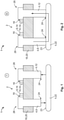
- Figures 1 and 2 show a first exemplary embodiment of a contact arrangement 1.
- the contact arrangement 1 includes a measuring device 2 for detecting a contacting state of the contact arrangement 1 and at least two electrical contacts 4, which are electrically isolated from one another in a first, open contacting state T (see Fig. 1 ) and are electrically connected to one another in a second, closed contacting state K (see Fig. 2 ).
- the measuring device 2 comprises an acoustic signal transmitter 6, which is adapted to couple an acoustic signal, in particular a sound wave, into a first contact 8 of the at least two contacts 4, and a signal receiver 10, which is connected to a second contact 12 of the at least two contacts 4 in a sound-conducting manner.
- the sound wave can be transmitted directly via the contacts.
- the acoustic signal is conducted from the signal transmitter to the signal receiver via the structure-borne sound via the contacts of the contact arrangement. Since the acoustic signal, in contrast to a magnetic or electrical signal, is independent of the type and level of voltage, failures caused, for example, by light bridges, short circuits and/or welding can be reliably detected. Furthermore, the measuring device 2 and the method can be used in different contact arrangements without undue effort.
- the signal transmitter 6 and signal receiver 10 can be adapted to couple an acoustic signal in the ultrasonic range from about 16 kHz into the first contact 8 or to receive it from the second contact 12.
- signal transmitter 6 and signal receiver 10 can preferably be piezoelectric elements 14, with which a compact and low-wear measuring device 2 can be provided.
- An electrical isolator 16 in particular a galvanic isolator, can be arranged between the signal transmitter 6 and the first contact 8 and between the signal receiver 10 and the second contact 12 to ensure reliable electrical isolation between the contacts and the signal transmitter or signal receiver.
- the electrical isolator 16 may, for example, be made of a ceramic material comprising at least a similar sound conduction as the material of the electrical contacts 4. Consequently, the acoustic signal can be coupled from the signal transmitter 6 into the first contact 8 via the electrical isolator 16, or the acoustic signal can be received by the signal receiver 10 from the second contact 12 via the electrical isolator 16, without any major fluctuations in its parameters.
- first contact 8 and second contact 12 may be held stationary in the contact arrangement 1.
- the first and second contacts 8, 12 may be held on a common carrier 18, for example a housing wall.
- the carrier 18 may serve as a damping element 20, which has a lower acoustic conductivity than the material of the contacts 4.
- the acoustic signal may be transmitted between the first and second contacts 8, 12 via the damping element 20, thereby verifying that the measuring device 2 is ready for operation.
- a further electrical contact 4 serving as a bridging contact 22 can be provided.
- the bridging contact 22 can be held movably relative to the first and second contacts 8, 12, wherein the bridging contact 22 comprises an abutment surface 23 facing the respective first and second contacts 8, 12, which abutment surface is spaced apart from at least one of the first and second contacts 8, 12 in the open contacting state T and abuts a respective contacting end 24 of the first and second contacts 8, 12 in the closed contacting state K. Consequently, not only is transmission of the electric current via the bridging contact 22 ensured, but also transmission of the structure-borne sound.
- the sound wave can be conducted from the signal transmitter 6 to the signal receiver 10 with the least resistance.
- the closed contacting state K is dissolved by moving the bridging contact 22 away from at least one of the first and second contacts 8, 12, an air bridge is generated between the contacting end 24 and the abutment surface 23, which has a damping effect on the sound wave, particularly in the ultrasonic range. Furthermore, the distance the sound wave has to travel to get from the signal transmitter to the signal receiver is increased.
- Signal transmitter 6 and/or signal receiver 10 can preferably be arranged at an end 26 of the respective contact 8, 12 facing away from the contacting end 24 so that the acoustic signal propagates directionally over the entire contact and measurement errors can be avoided.
- the contact arrangement 1 may also comprise two contacts which are movable relative to each other and which directly abut against each other in the closed contacting state K.
- the contact arrangement 1 can be part of an electrical switching device 27.
- a retrofit kit may comprise a measuring device 2 which can be integrated in a contact arrangement comprising at least two contacts.
- the measuring device 2 may be adapted to output a representative signal for at least one of the following parameters: running time; sound pressure; sound energy; and sound intensity.
- the measuring device 2 may be adapted to output a measurement signal representative of the acoustic intensity and a measurement signal representative of the running time of the acoustic signal.
- the sound intensity can be dampened by air or a contact-inhibiting layer of dirt located between the abutment surface 23 and the contacting end 24, it is possible to reflect whether or not electrical contacting is taking place by considering the measurement signal representative of the sound intensity.
- the measurement of the running time of the acoustic signal can in particular be related to the zero crossings, i.e. the phase change, of the acoustic signal. Consequently, the zero crossing of the acoustic signal at the signal transmitter 6 is considered the starting point and the zero crossing of the acoustic signal at the signal receiver 10 is considered the end point. This is preferred because the phase change of the acoustic signal is less influenced by disturbances, for example, sound reflection, in contrast to the other sound parameters. Since the running time of the acoustic signal is proportional to the travel path of the acoustic signal, the distance between the contacts 4, which are adapted to abut directly against each other, can be determined when considering the measurement signal representative of the running time.
- failures can be avoided or at least detected.
- the onset of levitation can be detected at high short-circuit currents, which can cause arcing resulting in two contacts welding together.
- the measurement can preferably take place continuously so that changes in the contacting state can be registered at any time. However, if continuous operation of the measuring device is to be avoided, the measurement can also take place in a pulsed manner, for example as a function of a switching signal.
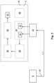
- Fig. 3 shows a schematic sketch of a block diagram of an exemplary configuration of a measuring device.
- At least one of the two measurement signals can be read out and the contacting state of the contact arrangement can be determined on the basis of its measurement parameter.
- the block diagram shows the signal transmitter 6, which couples the acoustic signal 28 into the first contact, and the signal receiver 10, which receives the acoustic signal 28 with a sound intensity I and after a running time t. Based on the acoustic signal 28 received by the signal receiver 10, a measurement signal 30 representative of the sound intensity I of the acoustic signal 28 and a measurement signal 32 representative of the running time t of the acoustic signal 28 can be output.
- the storage unit 34 can be integrated in a computer system C or at least can be read out by a computer system C.
- the computer system C may have a readout unit 36 which can access the measurement signals 30, 32 stored on the storage unit 34.
- the read out measurement signals 30, 32 can be evaluated via an evaluation unit 38 and the corresponding contacting state can be determined.
- the evaluation unit 38 can be coupled to an output unit 40 which outputs the contacting state and/or the distance between two contacts which abut against each other at least in the closed contacting state on the basis of an output value 42.
- the computer system C may be a data processing system and comprise a processor 44 configured such that it executes the computer-implemented method.
- Commands for executing the method may be stored on a computer-readable storage medium 46, for example, the commands causing the computer system C to execute the method.
- the computer system can be integrated in the contact arrangement or decoupled from it. If the computer system C is decoupled from the contact arrangement, a connection can be provided via which the measurement signals can be accessed.
- the computer system may also include a command unit (not shown) that may be coupled to the signal transmitter 6 and may cause the signal transmitter to couple the acoustic signal into the first contact 8.
- a command unit (not shown) that may be coupled to the signal transmitter 6 and may cause the signal transmitter to couple the acoustic signal into the first contact 8.
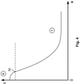
- Fig. 4 shows an exemplary sketch of a diagram showing the course of the sound intensity as a function of the contacting distance.
- the sound intensity I is on the ordinate and the distance x of the contacts to be contacted is on the abscissa.
- the sound intensity of the acoustic signal at the signal receiver reaches its maximum. If the contacts are now moved away from each other, the sound intensity decreases continuously due to the air bridge between the contacts, wherein the contacting state is changed from closed K to open T when the value falls below a threshold value 50.
- the threshold value 50 is only schematically drawn in the diagram and can vary depending on the contact arrangement.
- the threshold value can, for example, be stored in the system by means of calibration and represent the value at which no current flow occurs between the contacts to be contacted. Consequently, for any value of sound intensity I above the threshold 50, an output value representative of the closed contacting state K can be output.
- the consideration of the sound intensity is less suitable, since this is exposed to additional fluctuations by the reflection and the like. If a statement about the exact distance between the contacts is to be made, a consideration of the running time is better suited, since this is exposed to smaller fluctuations in comparison to the remaining sound quantities and can be combined simply with the sound intensity.
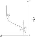
- FIG. 5 A diagram showing the course of the running time t as a function of the contacting distance x is shown in Fig. 5 .
- a threshold value 50 can be specified, with any value below the threshold value 50 suggesting a closed contacting state K and any value above the threshold value 50 suggesting an open contacting state T.
Landscapes
- Physics & Mathematics (AREA)
- General Physics & Mathematics (AREA)
- Engineering & Computer Science (AREA)
- Theoretical Computer Science (AREA)
- Microelectronics & Electronic Packaging (AREA)
- Measurement Of Mechanical Vibrations Or Ultrasonic Waves (AREA)
- Investigating Or Analyzing Materials By The Use Of Ultrasonic Waves (AREA)
- A Measuring Device Byusing Mechanical Method (AREA)
Abstract
Description
- The invention relates to a contact arrangement having a measuring device and to a method for measuring a contacting state, in particular a contact arrangement for the high-voltage and/or high-current range.
- Such contact arrangements have two contacts which are electrically conductively connected to each other in a closed position and electrically isolated from each other in an isolated position. The contact arrangements can comprise a detector which allows to determine whether the contacts are isolated or closed. In this case, the contacting state is only measured indirectly via the position of an actuating element. However, this means that a state of failure in which, for example, one of the contacts is welded to the contact bridge cannot be detected or falsely declared as open or closed. Consequently, such contact arrangements are unsafe. Detectors registering changes in the electric and/or magnetic field are mostly also dependent on the level and type of the switched voltage and therefore cannot be used arbitrarily for different contact arrangements.
- The object of the invention is to provide a solution which can detect the contacting state of two contacts more reliably and in a versatile manner.
- According to the invention, this is solved by a contact arrangement having a measuring device for detecting a contacting state of the contact arrangement and having at least two electrical contacts which are electrically isolated from one another in a first, open, contacting state and are electrically connected to one another in a second, closed, contacting state. The measuring device comprises an acoustic signal generator, which is adapted to couple an acoustic signal, in particular a sound wave, into a first of the at least two contacts, and a signal receiver, which is connected to a second of the at least two contacts in a sound-conducting manner.
- In a method according to the invention for measuring a contacting state of a contact arrangement having at least two contacts, this is solved by coupling an acoustic signal into a first contact of the at least two contacts and receiving the acoustic signal at a second contact of the at least two contacts.
- The invention further relates to a computer-implemented method comprising, according to the invention, the following steps:
- providing a measurement signal representative of an acoustic signal transmitted from one contact of a contact arrangement to another contact of the contact arrangement, wherein the measurement signal includes at least one measurement parameter representative of at least one of the following parameters of the acoustic signal:
- running time;
- sound pressure;
- sound energy; and
- sound intensity;
- determining a contacting state of the contact arrangement based on the at least one measurement parameter.
- By the solution according to the invention, it is ensured that the contacting state is measured directly via the contacts. The acoustic signal is conducted by means of structure-borne sound via the contacts of the contact arrangement from the signal transmitter to the signal receiver. Because the signal transmitter couples the acoustic signal into one contact and the signal receiver receives the signal at another contact, a measurement based on transmission takes place. In contrast to an indirect measurement based on reflection, in which the signal transmitter and signal receiver are arranged on the same contact and the reflection of the acoustic signal is registered on an actuating element, a higher level of safety is ensured. In the reflective measurement of the position of the actuating element for moving one contact relative to the other contact, for example, welding of the contacts cannot be detected, because the actuating element remains unaffected by the welding. Since the acoustic signal, in contrast to a magnetic or electrical signal, is independent of the type and level of voltage, failures caused, for example, by light bridges, short circuits and/or welding can be reliably detected. Furthermore, the measuring device and the method can be applied to different contact devices without undue effort.
- The solution according to the invention can be further improved with the following further developments and configurations, each of which is advantageous in itself and can be arbitrarily combined with one another.
- In a first preferred configuration, signal transmitters and/or signal receivers can be directly connected to the respective contacts. This allows the acoustic signal to be coupled directly into the contact or to be received by the contact without greatly influencing the parameters of the acoustic signal, which can further simplify the evaluation or provision of the measurement signal.
- Preferably, however, signal transmitter and/or signal receiver can be indirectly connected to the respective contact via at least one electrical isolator, in particular a galvanic isolator, such as a ceramic plate. Consequently, a short circuit can be prevented by a contact between the electrical components of the signal transmitter and/or signal receiver and the respective electrical contact.
- The electrical isolator can be made of a material that has a similar, in particular the same, sound conduction as the material of the respective contact. The sound conduction depends on the density, transverse contraction coefficient, elastic modulus and shear modulus of the material. By selecting a suitable material of the electrical isolator, fluctuations in the parameters of the sound wave, in particular of the structure-borne sound, are avoided at the transitions between the isolator and the contact.
- The signal transmitter and/or signal receiver can be adapted in particular to couple or receive an acoustic signal in the ultrasonic range, in particular from 16 kHz. Since an ultrasonic wave lies above the range audible to humans, undesirable noise pollution can thus be prevented by the measuring device.
- The signal transmitter and/or signal receiver can in particular be a piezoelectric element, which can provide high precision and reliability over large measuring ranges. Furthermore, these piezoelectric elements are long-term stable and compact.
- In a preferred configuration, the device, in particular the measuring device, can be adapted to output a measurement signal representative of at least one of the following parameters: running time; sound pressure; sound energy; and sound intensity.
- A measurement signal that is representative of the sound intensity can be particularly advantageous in order to obtain the most accurate possible measurement of the contacting state with low vulnerability to error. Thus, in particular in the case of an ultrasonic wave, the presence of an air path or a layer of dirt leads to an attenuation of the sound intensity. Consequently, it is possible to detect a distance between the contacts or a contact inhibiting layer occurring between contacts which are in contact with each other.
- If the measurement signal is to be representative of the propagation time of the sound wave from the signal transmitter to the signal receiver, the zero crossing, i.e. the phase change, of the sound wave can be considered as a reference point for the running time. Compared to the remaining sound parameters of the sound wave, the zero crossing of the sound wave is not influenced or at least less influenced by disturbances, e.g. sound reflection, transmission, absorption and dissipation. Therefore, when considering the duration required for the sound wave to travel from the signal transmitter to the signal receiver via the at least two contacts, a very accurate measurement signal can be output. This accuracy not only allows a conclusion to be drawn about the contacting state of the contact arrangement, but also about the distance between two contacts which are adapted to be in abutment against each other.
- In a further preferred configuration, the measuring device can be adapted to output a measurement signal representative of the running time of the sound wave and a measurement signal representative of the sound intensity. The measurement signal representative of the sound intensity can be used to generate an output value representative of the contacting state with little effort, which can also be used to implement a circuit, for example. If a more precise analysis of the distance is required, an output value can be generated via the measurement signal representative of the running time of the sound wave.
- The measurement can preferably take place continuously so that failures can be registered at any time. In particular, this enables the detection of the onset of levitation, i.e. the brief isolation of the contacts due to a short circuit, which can result in an electric arc with a high voltage. This signals that the contact arrangement should be replaced to ensure safe operation.
- As an alternative to continuous measurement, the measurement can also be done at time intervals, in particular at uniform time intervals. For example, the signal transmitter can couple the acoustic signal into the first of the at least two contacts as a function of a switching signal. By avoiding continuous operation, the wear of the measuring device can be reduced. In a computer-implemented method, a command unit can be provided for this purpose, for example, via which the switching signal can be controlled.
- The contact arrangement may comprise two contacts that are movable relative to each other. Thus, for example, the contact arrangement can be a switching arrangement, as in a relay. The contacts may comprise contacting ends with which they abut against each other in the closed contacting state. For example, one contact can be held stationary in the contact arrangement and the other contact can be movable. The movable contact can be moved, for example, by an actuator.
- According to a further preferred configuration, more than two contacts can also be provided in the contact arrangement. For example, the contact arrangement can comprise three contacts, wherein one contact can be adapted as a bridge contact which is movable relative to the two other contacts, or at least one of them, and via which the two other contacts are electrically connected to each other in the closed contacting state. Consequently, the structure-borne sound is conducted from one contact to the other contact via the bridge contact.
- If more than two contacts are provided in the contact arrangement, it is preferred if the signal transmitter is connected to a contact arranged at the first position in a switching row of the contact arrangement in a sound-conducting manner and the signal receiver is connected to a contact arranged at the last position in the switching row in a sound-conducting manner. Consequently, the acoustic signal can be conducted directly from the signal transmitter to the signal receiver via all contacts present in the switching row.
- The contact arranged in the first position and the contact arranged in the last position can both be held stationary in the contact arrangement. The intermediate contacts can be movable relative to the two stationary contacts and serve as bridging contacts.
- Preferably, all contacts of the switching row can be formed from the same material, or at least have approximately the same sound conduction, which can facilitate the evaluation of the measurement signal, since the characteristics of the propagation of the structure-borne sound remain essentially constant over the entire switching row.
- An electrically isolating damping element can be arranged between the at least two contacts so that a structure-borne sound can be conducted from the first of the at least two contacts to the second of the at least two contacts via the damping element even in the isolated state. Thus, an acoustic signal can be recorded by the signal receiver even in the completely isolated state, allowing a measurement signal representative of a parameter, for example, the sound intensity, to be determined, which can correspond to a reference signal for the open contacting state. This reference signal can be used to ensure that the measuring device is functioning properly.
- The damping element can preferably have a lower sound conductivity than the at least two contacts so that at least in the closed contacting state the structure-borne sound conducted via the contacts overlaps the structure-borne sound conducted via the damping element. The structure-borne sound conducted via the damping element can also be used, for example, to calibrate the measuring device.
- In a further preferred configuration, the damping element can be realized as a carrier in which the at least two contacts are rigidly fixed. The damping element can be a housing wall, for example. The at least two contacts can each comprise a contacting end which is adapted to abut against a further contact at least in the closed position and thus to establish an electrical connection. In order to conduct the acoustic signal in a directed manner over the entire contact, it is preferred if the signal transmitter and/or signal receiver is connected to the respective contact at an end of the contact facing away from the contacting end.
- The measurement signal can be evaluated in the computer-implemented method, for example. For this purpose, an evaluation unit can be provided which uses the measurement signal to determine an output value representative of the contacting state and/or the distance between the contacts to be contacted, in particular the contacts to be contacted directly. Preferably, an output unit can be provided which outputs the output value determined by the evaluation unit.
- Preferably, a system for data processing may be provided comprising a processor, in particular a signal processor, configured to execute the computer-implemented method.
- A computer-readable storage medium may store instructions which, when executed by a computer, cause the computer to execute the computer-implemented method.
- The computer-implemented method can in particular be executed continuously during operation, and the evaluation unit can be connected to the signal transmitter and/or signal receiver. Alternatively, a storage unit can be provided on which the measurement signal or even its course can be stored. This storage unit can be read out if required, for example, by means of a readout unit coupled to the evaluation unit.
- A measuring device according to any of the foregoing configurations may be adapted as a retrofit kit, wherein the measuring device is configured to be integrated into a contact arrangement comprising at least two contacts.
- In the following, the invention is explained in more detail by means of preferred configurations with reference to the drawings. The preferred further developments and configurations shown are independent of each other and can be combined with each other as required in an application case.
- It is shown by:
- Fig. 1
- a schematic front view of an exemplary configuration of a contact arrangement according to the invention in a first, open contacting state;
- Fig. 2
- a schematic front view of the exemplary configuration of
Fig. 1 in a second, closed contacting state; - Fig. 3
- a schematic sketch of a block diagram of an exemplary configuration of a contact arrangement according to the invention;
- Fig. 4
- a schematic sketch of the course of the sound intensity with increasing distance between the contacts to be contacted; and
- Fig. 5
- a schematic sketch of the course of the running time with increasing distance between the contacts to be contacted.
-
Figures 1 and 2 show a first exemplary embodiment of acontact arrangement 1. - The
contact arrangement 1 includes ameasuring device 2 for detecting a contacting state of thecontact arrangement 1 and at least two electrical contacts 4, which are electrically isolated from one another in a first, open contacting state T (seeFig. 1 ) and are electrically connected to one another in a second, closed contacting state K (seeFig. 2 ). The measuringdevice 2 comprises anacoustic signal transmitter 6, which is adapted to couple an acoustic signal, in particular a sound wave, into a first contact 8 of the at least two contacts 4, and asignal receiver 10, which is connected to a second contact 12 of the at least two contacts 4 in a sound-conducting manner. - By coupling the
signal transmitter 6 and thesignal receiver 10 at different contacts of the contact arrangement, the sound wave can be transmitted directly via the contacts. The acoustic signal is conducted from the signal transmitter to the signal receiver via the structure-borne sound via the contacts of the contact arrangement. Since the acoustic signal, in contrast to a magnetic or electrical signal, is independent of the type and level of voltage, failures caused, for example, by light bridges, short circuits and/or welding can be reliably detected. Furthermore, the measuringdevice 2 and the method can be used in different contact arrangements without undue effort. - The
signal transmitter 6 and signalreceiver 10 can be adapted to couple an acoustic signal in the ultrasonic range from about 16 kHz into the first contact 8 or to receive it from the second contact 12. For this purpose,signal transmitter 6 and signalreceiver 10 can preferably be piezoelectric elements 14, with which a compact and low-wear measuring device 2 can be provided. - An
electrical isolator 16, in particular a galvanic isolator, can be arranged between thesignal transmitter 6 and the first contact 8 and between thesignal receiver 10 and the second contact 12 to ensure reliable electrical isolation between the contacts and the signal transmitter or signal receiver. Theelectrical isolator 16 may, for example, be made of a ceramic material comprising at least a similar sound conduction as the material of the electrical contacts 4. Consequently, the acoustic signal can be coupled from thesignal transmitter 6 into the first contact 8 via theelectrical isolator 16, or the acoustic signal can be received by thesignal receiver 10 from the second contact 12 via theelectrical isolator 16, without any major fluctuations in its parameters. - As can be seen in
Figures 1 and 2 , first contact 8 and second contact 12 may be held stationary in thecontact arrangement 1. The first and second contacts 8, 12 may be held on a common carrier 18, for example a housing wall. The carrier 18 may serve as a damping element 20, which has a lower acoustic conductivity than the material of the contacts 4. Thus, in the open state T, the acoustic signal may be transmitted between the first and second contacts 8, 12 via the damping element 20, thereby verifying that the measuringdevice 2 is ready for operation. - For opening or closing the electrical contacts 4, in particular the first and second contacts 8, 12, a further electrical contact 4 serving as a bridging contact 22 can be provided. The bridging contact 22 can be held movably relative to the first and second contacts 8, 12, wherein the bridging contact 22 comprises an
abutment surface 23 facing the respective first and second contacts 8, 12, which abutment surface is spaced apart from at least one of the first and second contacts 8, 12 in the open contacting state T and abuts a respective contactingend 24 of the first and second contacts 8, 12 in the closed contacting state K. Consequently, not only is transmission of the electric current via the bridging contact 22 ensured, but also transmission of the structure-borne sound. - If the first and second contacts 8, 12 are connected to each other, a continuous path for the propagation of the structure-borne sound from the signal transmitter to the signal receiver is ensured. Therefore, in the closed contacting state K, the sound wave can be conducted from the
signal transmitter 6 to thesignal receiver 10 with the least resistance. However, if the closed contacting state K is dissolved by moving the bridging contact 22 away from at least one of the first and second contacts 8, 12, an air bridge is generated between the contactingend 24 and theabutment surface 23, which has a damping effect on the sound wave, particularly in the ultrasonic range. Furthermore, the distance the sound wave has to travel to get from the signal transmitter to the signal receiver is increased. -
Signal transmitter 6 and/orsignal receiver 10 can preferably be arranged at anend 26 of the respective contact 8, 12 facing away from the contactingend 24 so that the acoustic signal propagates directionally over the entire contact and measurement errors can be avoided. - Of course, the
contact arrangement 1 may also comprise two contacts which are movable relative to each other and which directly abut against each other in the closed contacting state K. - The
contact arrangement 1 can be part of an electrical switching device 27. - Furthermore, a retrofit kit may comprise a
measuring device 2 which can be integrated in a contact arrangement comprising at least two contacts. - The measuring
device 2 may be adapted to output a representative signal for at least one of the following parameters: running time; sound pressure; sound energy; and sound intensity. - According to this exemplary configuration, the measuring
device 2 may be adapted to output a measurement signal representative of the acoustic intensity and a measurement signal representative of the running time of the acoustic signal. - Since the sound intensity can be dampened by air or a contact-inhibiting layer of dirt located between the
abutment surface 23 and the contactingend 24, it is possible to reflect whether or not electrical contacting is taking place by considering the measurement signal representative of the sound intensity. - The measurement of the running time of the acoustic signal can in particular be related to the zero crossings, i.e. the phase change, of the acoustic signal. Consequently, the zero crossing of the acoustic signal at the
signal transmitter 6 is considered the starting point and the zero crossing of the acoustic signal at thesignal receiver 10 is considered the end point. This is preferred because the phase change of the acoustic signal is less influenced by disturbances, for example, sound reflection, in contrast to the other sound parameters. Since the running time of the acoustic signal is proportional to the travel path of the acoustic signal, the distance between the contacts 4, which are adapted to abut directly against each other, can be determined when considering the measurement signal representative of the running time. - By combining the two measurement signals, failures can be avoided or at least detected. For example, the onset of levitation can be detected at high short-circuit currents, which can cause arcing resulting in two contacts welding together.
- The measurement can preferably take place continuously so that changes in the contacting state can be registered at any time. However, if continuous operation of the measuring device is to be avoided, the measurement can also take place in a pulsed manner, for example as a function of a switching signal.
-
Fig. 3 shows a schematic sketch of a block diagram of an exemplary configuration of a measuring device. - In the computer-implemented method, at least one of the two measurement signals can be read out and the contacting state of the contact arrangement can be determined on the basis of its measurement parameter.
- The block diagram shows the
signal transmitter 6, which couples theacoustic signal 28 into the first contact, and thesignal receiver 10, which receives theacoustic signal 28 with a sound intensity I and after a running time t. Based on theacoustic signal 28 received by thesignal receiver 10, ameasurement signal 30 representative of the sound intensity I of theacoustic signal 28 and ameasurement signal 32 representative of the running time t of theacoustic signal 28 can be output. - These measurement signals 30, 32 can be stored on a
storage unit 34. Thestorage unit 34 can be integrated in a computer system C or at least can be read out by a computer system C. For this purpose, the computer system C may have areadout unit 36 which can access the measurement signals 30, 32 stored on thestorage unit 34. - The read out measurement signals 30, 32 can be evaluated via an
evaluation unit 38 and the corresponding contacting state can be determined. Theevaluation unit 38 can be coupled to anoutput unit 40 which outputs the contacting state and/or the distance between two contacts which abut against each other at least in the closed contacting state on the basis of anoutput value 42. - In particular, the computer system C may be a data processing system and comprise a processor 44 configured such that it executes the computer-implemented method.
- Commands for executing the method may be stored on a computer-
readable storage medium 46, for example, the commands causing the computer system C to execute the method. - The computer system can be integrated in the contact arrangement or decoupled from it. If the computer system C is decoupled from the contact arrangement, a connection can be provided via which the measurement signals can be accessed.
- The computer system may also include a command unit (not shown) that may be coupled to the
signal transmitter 6 and may cause the signal transmitter to couple the acoustic signal into the first contact 8. -
Fig. 4 shows an exemplary sketch of a diagram showing the course of the sound intensity as a function of the contacting distance. - In the diagram, the sound intensity I is on the ordinate and the distance x of the contacts to be contacted is on the abscissa.
- At a contact distance of 0, i.e. when the contacts abut each other, the sound intensity of the acoustic signal at the signal receiver reaches its maximum. If the contacts are now moved away from each other, the sound intensity decreases continuously due to the air bridge between the contacts, wherein the contacting state is changed from closed K to open T when the value falls below a
threshold value 50. Thethreshold value 50 is only schematically drawn in the diagram and can vary depending on the contact arrangement. The threshold value can, for example, be stored in the system by means of calibration and represent the value at which no current flow occurs between the contacts to be contacted. Consequently, for any value of sound intensity I above thethreshold 50, an output value representative of the closed contacting state K can be output. - In particular for an analysis of the exact distance between the contacts, the consideration of the sound intensity is less suitable, since this is exposed to additional fluctuations by the reflection and the like. If a statement about the exact distance between the contacts is to be made, a consideration of the running time is better suited, since this is exposed to smaller fluctuations in comparison to the remaining sound quantities and can be combined simply with the sound intensity.
- A diagram showing the course of the running time t as a function of the contacting distance x is shown in
Fig. 5 . - Here, too, a
threshold value 50 can be specified, with any value below thethreshold value 50 suggesting a closed contacting state K and any value above thethreshold value 50 suggesting an open contacting state T. -
- 1
- contact arrangement
- 2
- measuring device
- 4
- electrical contact
- 6
- signal transmitter
- 8
- first electrical contact
- 10
- signal receiver
- 12
- second electrical contact
- 14
- piezoelectric element
- 16
- electrical isolator
- 18
- carrier
- 20
- damping element
- 22
- bridging contact
- 23
- abutment surface
- 24
- contacting end
- 26
- end facing away from the contacting end
- 27
- electrical switching device
- 28
- acoustic signal
- 30
- measurement signal
- 32
- measurement signal
- 34
- storage unit
- 36
- readout unit
- 38
- evaluation unit
- 40
- output unit
- 42
- output value
- 44
- processor
- 46
- storage medium
- 50
- threshold value
- C
- computer system
- I
- sound intensity
- K
- closed contacting state
- T
- open contacting state
- t
- running time
- x
- distance
Claims (15)
- Contact arrangement (1) comprising a measuring device (2) for determining a contacting state of the contact arrangement (1) and at least two electrical contacts (4), which in a first, open contacting state (T) are electrically isolated from one another and in a second, closed contacting state (K) are electrically connected to one another, wherein the measuring device (2) comprises an acoustic signal transmitter (6), which is configured to couple an acoustic signal (28) into a first contact (8) of the at least two contacts (4), and a signal receiver (10), which is connected to a second contact (12) of the at least two contacts (4) in a sound-conducting manner.
- Contact arrangement (1) according to claim 1, wherein the acoustic signal transmitter (6) is adapted to couple the acoustic signal (28) in the ultrasonic range.
- Contact arrangement (1) according to claim 1 or 2, wherein the measuring device (2) is adapted to output a measurement signal (30, 32) representative of at least one of the following parameters of the acoustic signal (28):- running time (t);- sound pressure;- sound energy; and- sound intensity (I).
- Contact arrangement (1) according to claim 3, wherein the measuring device (2) is adapted to output a first measurement signal (30) representative of the sound intensity (I) of the acoustic signal (28) and a second measurement signal (32) representative of the running time (t) of the acoustic signal (28).
- Contact arrangement (1) according to one of claims 1 to 4, wherein an electrically isolating damping element (20) extending between the at least two contacts (4) is arranged at least in the open contacting state (T).
- Contact arrangement (1) according to one of claims 1 to 5, wherein the contact arrangement (1) comprises a bridge contact (22) which is movable relative to the first and/or second contact (8, 12) and via which the first and second contacts (8, 12) are electrically connected to one another in the closed contacting state (K).
- Contact arrangement (1) according to one of claims 1 to 6, wherein signal transmitter (6) and/or signal receiver (10) is arranged at an end (26) of the respective contact (8, 12) arranged opposite a contacting end (24).
- Method for measuring a contacting state in a contact arrangement (1) comprising at least two electrical contacts (4) which are electrically isolated from each other in a first, open, contacting state (T) and electrically connected to each other in a second, closed, contacting state (K), comprising the following steps:- coupling an acoustic signal (28) into a first electrical contact (8) of the at least two electrical contacts (4); and- receiving the acoustic signal (28) at a second electrical contact (12) of the at least two electrical contacts (4).
- Method according to claim 8, wherein an acoustic signal (28) is continuously coupled into the first electrical contact (8).
- Method according to claim 8, wherein the acoustic signal (28) is coupled into the first electrical contact (8) in response to a switching signal.
- Computer-implemented method comprising the steps of:- providing a measurement signal (30, 32) representative of an acoustic signal (28) transmitted from one electrical contact (4) of a contact arrangement (1) to another contact (4) of the contact arrangement (1), wherein the measurement signal (30, 32) includes at least one measurement parameter representative of at least one of the following parameters of the acoustic signal (28):- running time (t);- sound pressure;- sound energy; and- sound intensity (I);- determining a contacting state (K, T) of the contact arrangement (1) by means of the at least one measurement parameter.
- System for processing data (C) comprising a processor (44) configured such that it executes the method according to claim 11.
- Computer-readable storage medium (46) comprising commands which, when executed by a computer, cause the computer to execute the method according to claim 11.
- Electrical switching device (27) comprising a contact arrangement (1) according to one of claims 1 to 7.
- Retrofit kit for a contact arrangement (1) comprising at least two electrical contacts (4) which, in a first, open contacting state (T), are electrically isolated from one another and, in a second, closed contacting state (K), are electrically connected to one another, wherein the retrofit kit comprises a measuring device (2) having an acoustic signal transmitter (6) adapted to couple a sound wave (28) into a first electrical contact (8) of said at least two electrical contacts (4), and a signal receiver (10) adapted to be connected to a second electrical contact (12) of said at least two electrical contacts (4) in a sound conducting manner.
Applications Claiming Priority (1)
| Application Number | Priority Date | Filing Date | Title |
|---|---|---|---|
| DE102020122065.0A DE102020122065B4 (en) | 2020-08-24 | 2020-08-24 | Contact arrangement with a measuring device for detecting a contacting state of the contact arrangement by means of an acoustic signal |
Publications (2)
| Publication Number | Publication Date |
|---|---|
| EP3964848A1 true EP3964848A1 (en) | 2022-03-09 |
| EP3964848B1 EP3964848B1 (en) | 2024-08-07 |
Family
ID=77431208
Family Applications (1)
| Application Number | Title | Priority Date | Filing Date |
|---|---|---|---|
| EP21192378.4A Active EP3964848B1 (en) | 2020-08-24 | 2021-08-20 | Contact arrangement having a measuring device for determining a contacting state of the contact arrangement by means of an acoustic signal |
Country Status (6)
| Country | Link |
|---|---|
| US (1) | US12007443B2 (en) |
| EP (1) | EP3964848B1 (en) |
| JP (1) | JP7183359B2 (en) |
| KR (1) | KR102708394B1 (en) |
| CN (1) | CN114089225A (en) |
| DE (1) | DE102020122065B4 (en) |
Citations (6)
| Publication number | Priority date | Publication date | Assignee | Title |
|---|---|---|---|---|
| US5629864A (en) * | 1992-05-22 | 1997-05-13 | Siemens Aktiengesellschaft | Testing process for the quality control of electromagnetically actuated switching devices |
| US20050237064A1 (en) * | 2004-04-26 | 2005-10-27 | Kwark Young H | Apparatus and method for determining contact dynamics |
| US20130342292A1 (en) * | 2012-06-26 | 2013-12-26 | Hyundai Motor Company | Relay module for vehicle battery system |
| US20140191767A1 (en) * | 2013-01-08 | 2014-07-10 | Eaton Corporation | Detection and location of electrical connections having a micro-interface abnormality in an electrical system |
| US20160153847A1 (en) * | 2013-07-05 | 2016-06-02 | Torque And More (Tam) Gmbh | Solid borne sound wave phase delay comparison |
| US20200194191A1 (en) * | 2018-12-13 | 2020-06-18 | Eaton Intelligent Power Limited | Circuit interrupters with non-contact sensor systems for evaluating erosion of electrical contacts and related methods |
Family Cites Families (28)
| Publication number | Priority date | Publication date | Assignee | Title |
|---|---|---|---|---|
| US3560844A (en) | 1968-10-14 | 1971-02-02 | Teletype Corp | Method and apparatus for measuring the operating-time of an electromagnet,utilizing a piezoelectric device |
| JPS5588988A (en) * | 1978-12-27 | 1980-07-05 | Toshiba Corp | Ultrasonic detecting device for resistance welding |
| JPS58156851A (en) * | 1982-03-15 | 1983-09-17 | Toshiba Corp | Diagnosing device for damage of contact |
| JPH03261879A (en) * | 1990-03-12 | 1991-11-21 | Nec Corp | Substrate tester |
| US5566041A (en) | 1995-04-17 | 1996-10-15 | Houston Industries Incorporated | Zero-sequence opening of power distribution |
| EP0847110A4 (en) * | 1995-08-11 | 1998-11-11 | Shoshin Idosaka | Method and apparatus for signal generation to check for electric connection, and safety connector |
| JPH0961486A (en) * | 1995-08-28 | 1997-03-07 | Nec Corp | Soldering inspecting instrument |
| US6936008B2 (en) * | 1999-08-20 | 2005-08-30 | Zonare Medical Systems, Inc. | Ultrasound system with cableless coupling assembly |
| DE19945059A1 (en) * | 1999-09-20 | 2001-03-22 | Moeller Gmbh | Arrangement with a switching device and an evaluation device for determining the remaining service life |
| JP2001242211A (en) * | 2000-02-29 | 2001-09-07 | Hioki Ee Corp | Circuit board inspection equipment |
| US7411403B2 (en) * | 2005-05-10 | 2008-08-12 | Eaton Corporation | Electrical switching apparatus and method employing active acoustic sensing to detect an electrical conductivity fault of a power circuit |
| JP4294632B2 (en) * | 2005-10-26 | 2009-07-15 | 富士通メディアデバイス株式会社 | Surface acoustic wave device |
| JP4842041B2 (en) * | 2006-07-27 | 2011-12-21 | 富士通株式会社 | switch |
| JP5046609B2 (en) * | 2006-10-16 | 2012-10-10 | Hoya株式会社 | Ultrasonic diagnostic equipment |
| JP2010074938A (en) * | 2008-09-18 | 2010-04-02 | Nippon Telegr & Teleph Corp <Ntt> | Cable searching method and cable searching apparatus |
| EP2315229A1 (en) | 2009-10-20 | 2011-04-27 | ABB Research Ltd. | Status detection for a low voltage distribution board |
| DE102010008159A1 (en) | 2010-02-16 | 2011-09-08 | Autoliv Development Ab | Horn activation device |
| MX2012010864A (en) * | 2010-03-22 | 2013-04-03 | Mattel Inc | Electronic device and the input and output of data. |
| CN201935975U (en) * | 2010-10-15 | 2011-08-17 | 珠海共创电力安全技术股份有限公司 | State detection device of closing pressing plate switch |
| US8671551B2 (en) | 2011-02-01 | 2014-03-18 | The United States Of America As Represented By The Administrator Of The National Aeronautics And Space Administration | Process for nondestructive evaluation of the quality of a crimped wire connector |
| US20130096853A1 (en) * | 2011-10-14 | 2013-04-18 | General Electric Company | Systems and methods for monitoring electrical contacts |
| DE102011119306A1 (en) * | 2011-11-24 | 2013-05-29 | Daimler Ag | Contact pairing with a double contact point for an electrical switching device |
| KR101332184B1 (en) * | 2013-05-29 | 2013-11-22 | 유비벨록스(주) | System and method for manufacturing combi-type ic card |
| DE102014212132A1 (en) | 2014-06-25 | 2015-12-31 | Te Connectivity Germany Gmbh | switching arrangement |
| JP2017530383A (en) | 2014-07-30 | 2017-10-12 | コーニング インコーポレイテッド | High contrast glass-based writable / erasable front projection screen |
| CN104792869B (en) * | 2015-04-03 | 2018-01-05 | 上海和伍精密仪器股份有限公司 | The Ultrasonic Nondestructive system of low-voltage electrical apparatus electrical contact brazing quality |
| US9952184B2 (en) * | 2015-12-17 | 2018-04-24 | Schneider Electric It Corporation | Ultrasonic monitoring of electrical connections |
| JP6902447B2 (en) * | 2017-09-29 | 2021-07-14 | タツタ電線株式会社 | Inspection device and cable with inspection device |
-
2020
- 2020-08-24 DE DE102020122065.0A patent/DE102020122065B4/en active Active
-
2021
- 2021-08-19 JP JP2021133730A patent/JP7183359B2/en active Active
- 2021-08-20 EP EP21192378.4A patent/EP3964848B1/en active Active
- 2021-08-20 CN CN202110959226.4A patent/CN114089225A/en active Pending
- 2021-08-20 KR KR1020210110109A patent/KR102708394B1/en active Active
- 2021-08-24 US US17/410,377 patent/US12007443B2/en active Active
Patent Citations (6)
| Publication number | Priority date | Publication date | Assignee | Title |
|---|---|---|---|---|
| US5629864A (en) * | 1992-05-22 | 1997-05-13 | Siemens Aktiengesellschaft | Testing process for the quality control of electromagnetically actuated switching devices |
| US20050237064A1 (en) * | 2004-04-26 | 2005-10-27 | Kwark Young H | Apparatus and method for determining contact dynamics |
| US20130342292A1 (en) * | 2012-06-26 | 2013-12-26 | Hyundai Motor Company | Relay module for vehicle battery system |
| US20140191767A1 (en) * | 2013-01-08 | 2014-07-10 | Eaton Corporation | Detection and location of electrical connections having a micro-interface abnormality in an electrical system |
| US20160153847A1 (en) * | 2013-07-05 | 2016-06-02 | Torque And More (Tam) Gmbh | Solid borne sound wave phase delay comparison |
| US20200194191A1 (en) * | 2018-12-13 | 2020-06-18 | Eaton Intelligent Power Limited | Circuit interrupters with non-contact sensor systems for evaluating erosion of electrical contacts and related methods |
Non-Patent Citations (1)
| Title |
|---|
| ULTRAN GROUP: "Ultrasonic Transducers", 31 December 2018 (2018-12-31), pages 1 - 32, XP055881928, Retrieved from the Internet <URL:http://ultrangroup.com/wp-content/uploads/transducer-catalog.pdf> * |
Also Published As
| Publication number | Publication date |
|---|---|
| DE102020122065B4 (en) | 2022-12-01 |
| KR102708394B1 (en) | 2024-09-20 |
| DE102020122065A1 (en) | 2022-02-24 |
| CN114089225A (en) | 2022-02-25 |
| US12007443B2 (en) | 2024-06-11 |
| KR20220025675A (en) | 2022-03-03 |
| JP7183359B2 (en) | 2022-12-05 |
| JP2022036921A (en) | 2022-03-08 |
| EP3964848B1 (en) | 2024-08-07 |
| US20220057450A1 (en) | 2022-02-24 |
Similar Documents
| Publication | Publication Date | Title |
|---|---|---|
| EP2960923B1 (en) | Switching arrangement | |
| US20060090563A1 (en) | Ultrasonic fluid level sensor | |
| US20200194191A1 (en) | Circuit interrupters with non-contact sensor systems for evaluating erosion of electrical contacts and related methods | |
| US9625305B2 (en) | Ultrasonic transit-time flowmeter and method for detecting a failure in an ultrasonic transit-time flowmeter | |
| JPH01122530A (en) | Breaking performance deterioration predicting device for vacuum breaker | |
| US5204633A (en) | Electromagnetic contactor with closure fault indicator | |
| EP3964848B1 (en) | Contact arrangement having a measuring device for determining a contacting state of the contact arrangement by means of an acoustic signal | |
| US11170956B2 (en) | Switching arrangement | |
| CN101438363A (en) | System and method for monitoring displacement within an energized tap changer compartment | |
| HRP20241261T1 (en) | Level gauge with selectable quality level of a monitoring function | |
| JP7286724B2 (en) | Switching assembly and method for measuring the position of the contact bridge of the switching assembly | |
| JP2005172817A (en) | Throttle position sensor | |
| JP3445353B2 (en) | Operation monitoring device for power switchgear | |
| JPH08241653A (en) | Switch position detector | |
| EP4401105A1 (en) | Acoustic sensing of thomson coil based vacuum circuit interrupter operation | |
| JPH01232628A (en) | Breaker opening/closing abnormality detection device | |
| KR20250096225A (en) | Insulation monitoring device to reduce measurement error of insulation resistance | |
| US12498439B2 (en) | Inductive conductivity sensor circuit, inductive conductivity sensor and method of operating the circuit | |
| KR102888961B1 (en) | Electrical arrangement with redundant electrical transmission path and means for detecting error state of the same, and method for detecting error state of redundant electrical transmission path of electrical arrangement | |
| JPH09282981A (en) | Switch position detector | |
| JPH08251739A (en) | Power switchgear operation monitoring device | |
| SU752180A1 (en) | Microwave power meter | |
| JPH1095337A (en) | Transmitter trouble detector for atc device | |
| CN113125815A (en) | Electronic component testing device and probe | |
| JP2024114032A (en) | Outlet device |
Legal Events
| Date | Code | Title | Description |
|---|---|---|---|
| PUAI | Public reference made under article 153(3) epc to a published international application that has entered the european phase |
Free format text: ORIGINAL CODE: 0009012 |
|
| STAA | Information on the status of an ep patent application or granted ep patent |
Free format text: STATUS: THE APPLICATION HAS BEEN PUBLISHED |
|
| AK | Designated contracting states |
Kind code of ref document: A1 Designated state(s): AL AT BE BG CH CY CZ DE DK EE ES FI FR GB GR HR HU IE IS IT LI LT LU LV MC MK MT NL NO PL PT RO RS SE SI SK SM TR |
|
| STAA | Information on the status of an ep patent application or granted ep patent |
Free format text: STATUS: REQUEST FOR EXAMINATION WAS MADE |
|
| 17P | Request for examination filed |
Effective date: 20220325 |
|
| RBV | Designated contracting states (corrected) |
Designated state(s): AL AT BE BG CH CY CZ DE DK EE ES FI FR GB GR HR HU IE IS IT LI LT LU LV MC MK MT NL NO PL PT RO RS SE SI SK SM TR |
|
| RIC1 | Information provided on ipc code assigned before grant |
Ipc: G01R 31/327 20060101AFI20240229BHEP |
|
| GRAP | Despatch of communication of intention to grant a patent |
Free format text: ORIGINAL CODE: EPIDOSNIGR1 |
|
| STAA | Information on the status of an ep patent application or granted ep patent |
Free format text: STATUS: GRANT OF PATENT IS INTENDED |
|
| INTG | Intention to grant announced |
Effective date: 20240411 |
|
| GRAS | Grant fee paid |
Free format text: ORIGINAL CODE: EPIDOSNIGR3 |
|
| GRAA | (expected) grant |
Free format text: ORIGINAL CODE: 0009210 |
|
| STAA | Information on the status of an ep patent application or granted ep patent |
Free format text: STATUS: THE PATENT HAS BEEN GRANTED |
|
| AK | Designated contracting states |
Kind code of ref document: B1 Designated state(s): AL AT BE BG CH CY CZ DE DK EE ES FI FR GB GR HR HU IE IS IT LI LT LU LV MC MK MT NL NO PL PT RO RS SE SI SK SM TR |
|
| REG | Reference to a national code |
Ref country code: GB Ref legal event code: FG4D |
|
| REG | Reference to a national code |
Ref country code: CH Ref legal event code: EP |
|
| REG | Reference to a national code |
Ref country code: DE Ref legal event code: R096 Ref document number: 602021016712 Country of ref document: DE |
|
| REG | Reference to a national code |
Ref country code: IE Ref legal event code: FG4D |
|
| REG | Reference to a national code |
Ref country code: LT Ref legal event code: MG9D |
|
| REG | Reference to a national code |
Ref country code: NL Ref legal event code: MP Effective date: 20240807 |
|
| PG25 | Lapsed in a contracting state [announced via postgrant information from national office to epo] |
Ref country code: NO Free format text: LAPSE BECAUSE OF FAILURE TO SUBMIT A TRANSLATION OF THE DESCRIPTION OR TO PAY THE FEE WITHIN THE PRESCRIBED TIME-LIMIT Effective date: 20241107 |
|
| REG | Reference to a national code |
Ref country code: AT Ref legal event code: MK05 Ref document number: 1711518 Country of ref document: AT Kind code of ref document: T Effective date: 20240807 |
|
| PG25 | Lapsed in a contracting state [announced via postgrant information from national office to epo] |
Ref country code: NL Free format text: LAPSE BECAUSE OF FAILURE TO SUBMIT A TRANSLATION OF THE DESCRIPTION OR TO PAY THE FEE WITHIN THE PRESCRIBED TIME-LIMIT Effective date: 20240807 Ref country code: PL Free format text: LAPSE BECAUSE OF FAILURE TO SUBMIT A TRANSLATION OF THE DESCRIPTION OR TO PAY THE FEE WITHIN THE PRESCRIBED TIME-LIMIT Effective date: 20240807 Ref country code: PT Free format text: LAPSE BECAUSE OF FAILURE TO SUBMIT A TRANSLATION OF THE DESCRIPTION OR TO PAY THE FEE WITHIN THE PRESCRIBED TIME-LIMIT Effective date: 20241209 Ref country code: GR Free format text: LAPSE BECAUSE OF FAILURE TO SUBMIT A TRANSLATION OF THE DESCRIPTION OR TO PAY THE FEE WITHIN THE PRESCRIBED TIME-LIMIT Effective date: 20241108 Ref country code: FI Free format text: LAPSE BECAUSE OF FAILURE TO SUBMIT A TRANSLATION OF THE DESCRIPTION OR TO PAY THE FEE WITHIN THE PRESCRIBED TIME-LIMIT Effective date: 20240807 |
|
| PG25 | Lapsed in a contracting state [announced via postgrant information from national office to epo] |
Ref country code: BG Free format text: LAPSE BECAUSE OF FAILURE TO SUBMIT A TRANSLATION OF THE DESCRIPTION OR TO PAY THE FEE WITHIN THE PRESCRIBED TIME-LIMIT Effective date: 20240807 |
|
| PG25 | Lapsed in a contracting state [announced via postgrant information from national office to epo] |
Ref country code: LV Free format text: LAPSE BECAUSE OF FAILURE TO SUBMIT A TRANSLATION OF THE DESCRIPTION OR TO PAY THE FEE WITHIN THE PRESCRIBED TIME-LIMIT Effective date: 20240807 |
|
| PG25 | Lapsed in a contracting state [announced via postgrant information from national office to epo] |
Ref country code: AT Free format text: LAPSE BECAUSE OF FAILURE TO SUBMIT A TRANSLATION OF THE DESCRIPTION OR TO PAY THE FEE WITHIN THE PRESCRIBED TIME-LIMIT Effective date: 20240807 Ref country code: IS Free format text: LAPSE BECAUSE OF FAILURE TO SUBMIT A TRANSLATION OF THE DESCRIPTION OR TO PAY THE FEE WITHIN THE PRESCRIBED TIME-LIMIT Effective date: 20241207 |
|
| PG25 | Lapsed in a contracting state [announced via postgrant information from national office to epo] |
Ref country code: HR Free format text: LAPSE BECAUSE OF FAILURE TO SUBMIT A TRANSLATION OF THE DESCRIPTION OR TO PAY THE FEE WITHIN THE PRESCRIBED TIME-LIMIT Effective date: 20240807 |
|
| PG25 | Lapsed in a contracting state [announced via postgrant information from national office to epo] |
Ref country code: ES Free format text: LAPSE BECAUSE OF FAILURE TO SUBMIT A TRANSLATION OF THE DESCRIPTION OR TO PAY THE FEE WITHIN THE PRESCRIBED TIME-LIMIT Effective date: 20240807 Ref country code: RS Free format text: LAPSE BECAUSE OF FAILURE TO SUBMIT A TRANSLATION OF THE DESCRIPTION OR TO PAY THE FEE WITHIN THE PRESCRIBED TIME-LIMIT Effective date: 20241107 |
|
| PG25 | Lapsed in a contracting state [announced via postgrant information from national office to epo] |
Ref country code: RS Free format text: LAPSE BECAUSE OF FAILURE TO SUBMIT A TRANSLATION OF THE DESCRIPTION OR TO PAY THE FEE WITHIN THE PRESCRIBED TIME-LIMIT Effective date: 20241107 Ref country code: PT Free format text: LAPSE BECAUSE OF FAILURE TO SUBMIT A TRANSLATION OF THE DESCRIPTION OR TO PAY THE FEE WITHIN THE PRESCRIBED TIME-LIMIT Effective date: 20241209 Ref country code: PL Free format text: LAPSE BECAUSE OF FAILURE TO SUBMIT A TRANSLATION OF THE DESCRIPTION OR TO PAY THE FEE WITHIN THE PRESCRIBED TIME-LIMIT Effective date: 20240807 Ref country code: NO Free format text: LAPSE BECAUSE OF FAILURE TO SUBMIT A TRANSLATION OF THE DESCRIPTION OR TO PAY THE FEE WITHIN THE PRESCRIBED TIME-LIMIT Effective date: 20241107 Ref country code: NL Free format text: LAPSE BECAUSE OF FAILURE TO SUBMIT A TRANSLATION OF THE DESCRIPTION OR TO PAY THE FEE WITHIN THE PRESCRIBED TIME-LIMIT Effective date: 20240807 Ref country code: LV Free format text: LAPSE BECAUSE OF FAILURE TO SUBMIT A TRANSLATION OF THE DESCRIPTION OR TO PAY THE FEE WITHIN THE PRESCRIBED TIME-LIMIT Effective date: 20240807 Ref country code: IS Free format text: LAPSE BECAUSE OF FAILURE TO SUBMIT A TRANSLATION OF THE DESCRIPTION OR TO PAY THE FEE WITHIN THE PRESCRIBED TIME-LIMIT Effective date: 20241207 Ref country code: HR Free format text: LAPSE BECAUSE OF FAILURE TO SUBMIT A TRANSLATION OF THE DESCRIPTION OR TO PAY THE FEE WITHIN THE PRESCRIBED TIME-LIMIT Effective date: 20240807 Ref country code: GR Free format text: LAPSE BECAUSE OF FAILURE TO SUBMIT A TRANSLATION OF THE DESCRIPTION OR TO PAY THE FEE WITHIN THE PRESCRIBED TIME-LIMIT Effective date: 20241108 Ref country code: FI Free format text: LAPSE BECAUSE OF FAILURE TO SUBMIT A TRANSLATION OF THE DESCRIPTION OR TO PAY THE FEE WITHIN THE PRESCRIBED TIME-LIMIT Effective date: 20240807 Ref country code: ES Free format text: LAPSE BECAUSE OF FAILURE TO SUBMIT A TRANSLATION OF THE DESCRIPTION OR TO PAY THE FEE WITHIN THE PRESCRIBED TIME-LIMIT Effective date: 20240807 Ref country code: BG Free format text: LAPSE BECAUSE OF FAILURE TO SUBMIT A TRANSLATION OF THE DESCRIPTION OR TO PAY THE FEE WITHIN THE PRESCRIBED TIME-LIMIT Effective date: 20240807 Ref country code: AT Free format text: LAPSE BECAUSE OF FAILURE TO SUBMIT A TRANSLATION OF THE DESCRIPTION OR TO PAY THE FEE WITHIN THE PRESCRIBED TIME-LIMIT Effective date: 20240807 |
|
| REG | Reference to a national code |
Ref country code: CH Ref legal event code: PL |
|
| PG25 | Lapsed in a contracting state [announced via postgrant information from national office to epo] |
Ref country code: DK Free format text: LAPSE BECAUSE OF FAILURE TO SUBMIT A TRANSLATION OF THE DESCRIPTION OR TO PAY THE FEE WITHIN THE PRESCRIBED TIME-LIMIT Effective date: 20240807 Ref country code: SM Free format text: LAPSE BECAUSE OF FAILURE TO SUBMIT A TRANSLATION OF THE DESCRIPTION OR TO PAY THE FEE WITHIN THE PRESCRIBED TIME-LIMIT Effective date: 20240807 |
|
| PG25 | Lapsed in a contracting state [announced via postgrant information from national office to epo] |
Ref country code: LU Free format text: LAPSE BECAUSE OF NON-PAYMENT OF DUE FEES Effective date: 20240820 |
|
| PG25 | Lapsed in a contracting state [announced via postgrant information from national office to epo] |
Ref country code: CH Free format text: LAPSE BECAUSE OF NON-PAYMENT OF DUE FEES Effective date: 20240831 Ref country code: EE Free format text: LAPSE BECAUSE OF FAILURE TO SUBMIT A TRANSLATION OF THE DESCRIPTION OR TO PAY THE FEE WITHIN THE PRESCRIBED TIME-LIMIT Effective date: 20240807 |
|
| PG25 | Lapsed in a contracting state [announced via postgrant information from national office to epo] |
Ref country code: CZ Free format text: LAPSE BECAUSE OF FAILURE TO SUBMIT A TRANSLATION OF THE DESCRIPTION OR TO PAY THE FEE WITHIN THE PRESCRIBED TIME-LIMIT Effective date: 20240807 |
|
| PG25 | Lapsed in a contracting state [announced via postgrant information from national office to epo] |
Ref country code: SK Free format text: LAPSE BECAUSE OF FAILURE TO SUBMIT A TRANSLATION OF THE DESCRIPTION OR TO PAY THE FEE WITHIN THE PRESCRIBED TIME-LIMIT Effective date: 20240807 |
|
| REG | Reference to a national code |
Ref country code: DE Ref legal event code: R097 Ref document number: 602021016712 Country of ref document: DE |
|
| PLBE | No opposition filed within time limit |
Free format text: ORIGINAL CODE: 0009261 |
|
| STAA | Information on the status of an ep patent application or granted ep patent |
Free format text: STATUS: NO OPPOSITION FILED WITHIN TIME LIMIT |
|
| REG | Reference to a national code |
Ref country code: BE Ref legal event code: MM Effective date: 20240831 |
|
| PG25 | Lapsed in a contracting state [announced via postgrant information from national office to epo] |
Ref country code: MC Free format text: LAPSE BECAUSE OF FAILURE TO SUBMIT A TRANSLATION OF THE DESCRIPTION OR TO PAY THE FEE WITHIN THE PRESCRIBED TIME-LIMIT Effective date: 20240807 |
|
| PG25 | Lapsed in a contracting state [announced via postgrant information from national office to epo] |
Ref country code: BE Free format text: LAPSE BECAUSE OF NON-PAYMENT OF DUE FEES Effective date: 20240831 |
|
| 26N | No opposition filed |
Effective date: 20250508 |
|
| PGFP | Annual fee paid to national office [announced via postgrant information from national office to epo] |
Ref country code: FR Payment date: 20250610 Year of fee payment: 5 |
|
| PG25 | Lapsed in a contracting state [announced via postgrant information from national office to epo] |
Ref country code: IE Free format text: LAPSE BECAUSE OF NON-PAYMENT OF DUE FEES Effective date: 20240820 |
|
| PG25 | Lapsed in a contracting state [announced via postgrant information from national office to epo] |
Ref country code: SE Free format text: LAPSE BECAUSE OF FAILURE TO SUBMIT A TRANSLATION OF THE DESCRIPTION OR TO PAY THE FEE WITHIN THE PRESCRIBED TIME-LIMIT Effective date: 20240807 |
|
| PGFP | Annual fee paid to national office [announced via postgrant information from national office to epo] |
Ref country code: DE Payment date: 20250624 Year of fee payment: 5 |
|
| PG25 | Lapsed in a contracting state [announced via postgrant information from national office to epo] |
Ref country code: RO Free format text: LAPSE BECAUSE OF FAILURE TO SUBMIT A TRANSLATION OF THE DESCRIPTION OR TO PAY THE FEE WITHIN THE PRESCRIBED TIME-LIMIT Effective date: 20240807 |
|
| PG25 | Lapsed in a contracting state [announced via postgrant information from national office to epo] |
Ref country code: IT Free format text: LAPSE BECAUSE OF NON-PAYMENT OF DUE FEES Effective date: 20240820 |
|
| PG25 | Lapsed in a contracting state [announced via postgrant information from national office to epo] |
Ref country code: CY Free format text: LAPSE BECAUSE OF FAILURE TO SUBMIT A TRANSLATION OF THE DESCRIPTION OR TO PAY THE FEE WITHIN THE PRESCRIBED TIME-LIMIT; INVALID AB INITIO Effective date: 20210820 |
|
| PG25 | Lapsed in a contracting state [announced via postgrant information from national office to epo] |
Ref country code: HU Free format text: LAPSE BECAUSE OF FAILURE TO SUBMIT A TRANSLATION OF THE DESCRIPTION OR TO PAY THE FEE WITHIN THE PRESCRIBED TIME-LIMIT; INVALID AB INITIO Effective date: 20210820 |
|
| PG25 | Lapsed in a contracting state [announced via postgrant information from national office to epo] |
Ref country code: IT Free format text: LAPSE BECAUSE OF NON-PAYMENT OF DUE FEES Effective date: 20240820 |
|
| PGFP | Annual fee paid to national office [announced via postgrant information from national office to epo] |
Ref country code: IT Payment date: 20250722 Year of fee payment: 5 |
|
| PGRI | Patent reinstated in contracting state [announced from national office to epo] |
Ref country code: IT Effective date: 20240831 |
|
| GBPC | Gb: european patent ceased through non-payment of renewal fee |
Effective date: 20250820 |