EP3964783A1 - Vaporizer - Google Patents
Vaporizer Download PDFInfo
- Publication number
- EP3964783A1 EP3964783A1 EP20805415.5A EP20805415A EP3964783A1 EP 3964783 A1 EP3964783 A1 EP 3964783A1 EP 20805415 A EP20805415 A EP 20805415A EP 3964783 A1 EP3964783 A1 EP 3964783A1
- Authority
- EP
- European Patent Office
- Prior art keywords
- trough
- heat exchange
- slit
- vaporizer
- side wall
- Prior art date
- Legal status (The legal status is an assumption and is not a legal conclusion. Google has not performed a legal analysis and makes no representation as to the accuracy of the status listed.)
- Granted
Links
Images


Classifications
-
- F—MECHANICAL ENGINEERING; LIGHTING; HEATING; WEAPONS; BLASTING
- F17—STORING OR DISTRIBUTING GASES OR LIQUIDS
- F17C—VESSELS FOR CONTAINING OR STORING COMPRESSED, LIQUEFIED OR SOLIDIFIED GASES; FIXED-CAPACITY GAS-HOLDERS; FILLING VESSELS WITH, OR DISCHARGING FROM VESSELS, COMPRESSED, LIQUEFIED, OR SOLIDIFIED GASES
- F17C9/00—Methods or apparatus for discharging liquefied or solidified gases from vessels not under pressure
- F17C9/02—Methods or apparatus for discharging liquefied or solidified gases from vessels not under pressure with change of state, e.g. vaporisation
-
- F—MECHANICAL ENGINEERING; LIGHTING; HEATING; WEAPONS; BLASTING
- F28—HEAT EXCHANGE IN GENERAL
- F28D—HEAT-EXCHANGE APPARATUS, NOT PROVIDED FOR IN ANOTHER SUBCLASS, IN WHICH THE HEAT-EXCHANGE MEDIA DO NOT COME INTO DIRECT CONTACT
- F28D3/00—Heat-exchange apparatus having stationary conduit assemblies for one heat-exchange medium only, the media being in contact with different sides of the conduit wall, in which the other heat-exchange medium flows in a continuous film, or trickles freely, over the conduits
- F28D3/04—Distributing arrangements
-
- B—PERFORMING OPERATIONS; TRANSPORTING
- B63—SHIPS OR OTHER WATERBORNE VESSELS; RELATED EQUIPMENT
- B63B—SHIPS OR OTHER WATERBORNE VESSELS; EQUIPMENT FOR SHIPPING
- B63B25/00—Load-accommodating arrangements, e.g. stowing, trimming; Vessels characterised thereby
- B63B25/02—Load-accommodating arrangements, e.g. stowing, trimming; Vessels characterised thereby for bulk goods
- B63B25/08—Load-accommodating arrangements, e.g. stowing, trimming; Vessels characterised thereby for bulk goods fluid
- B63B25/12—Load-accommodating arrangements, e.g. stowing, trimming; Vessels characterised thereby for bulk goods fluid closed
- B63B25/16—Load-accommodating arrangements, e.g. stowing, trimming; Vessels characterised thereby for bulk goods fluid closed heat-insulated
-
- F—MECHANICAL ENGINEERING; LIGHTING; HEATING; WEAPONS; BLASTING
- F28—HEAT EXCHANGE IN GENERAL
- F28D—HEAT-EXCHANGE APPARATUS, NOT PROVIDED FOR IN ANOTHER SUBCLASS, IN WHICH THE HEAT-EXCHANGE MEDIA DO NOT COME INTO DIRECT CONTACT
- F28D3/00—Heat-exchange apparatus having stationary conduit assemblies for one heat-exchange medium only, the media being in contact with different sides of the conduit wall, in which the other heat-exchange medium flows in a continuous film, or trickles freely, over the conduits
- F28D3/02—Heat-exchange apparatus having stationary conduit assemblies for one heat-exchange medium only, the media being in contact with different sides of the conduit wall, in which the other heat-exchange medium flows in a continuous film, or trickles freely, over the conduits with tubular conduits
-
- F—MECHANICAL ENGINEERING; LIGHTING; HEATING; WEAPONS; BLASTING
- F28—HEAT EXCHANGE IN GENERAL
- F28D—HEAT-EXCHANGE APPARATUS, NOT PROVIDED FOR IN ANOTHER SUBCLASS, IN WHICH THE HEAT-EXCHANGE MEDIA DO NOT COME INTO DIRECT CONTACT
- F28D5/00—Heat-exchange apparatus having stationary conduit assemblies for one heat-exchange medium only, the media being in contact with different sides of the conduit wall, using the cooling effect of natural or forced evaporation
- F28D5/02—Heat-exchange apparatus having stationary conduit assemblies for one heat-exchange medium only, the media being in contact with different sides of the conduit wall, using the cooling effect of natural or forced evaporation in which the evaporating medium flows in a continuous film or trickles freely over the conduits
-
- F—MECHANICAL ENGINEERING; LIGHTING; HEATING; WEAPONS; BLASTING
- F28—HEAT EXCHANGE IN GENERAL
- F28F—DETAILS OF HEAT-EXCHANGE AND HEAT-TRANSFER APPARATUS, OF GENERAL APPLICATION
- F28F25/00—Component parts of trickle coolers
- F28F25/02—Component parts of trickle coolers for distributing, circulating, and accumulating liquid
- F28F25/04—Distributing or accumulator troughs
-
- F—MECHANICAL ENGINEERING; LIGHTING; HEATING; WEAPONS; BLASTING
- F28—HEAT EXCHANGE IN GENERAL
- F28F—DETAILS OF HEAT-EXCHANGE AND HEAT-TRANSFER APPARATUS, OF GENERAL APPLICATION
- F28F9/00—Casings; Header boxes; Auxiliary supports for elements; Auxiliary members within casings
- F28F9/02—Header boxes; End plates
- F28F9/026—Header boxes; End plates with static flow control means, e.g. with means for uniformly distributing heat exchange media into conduits
- F28F9/027—Header boxes; End plates with static flow control means, e.g. with means for uniformly distributing heat exchange media into conduits in the form of distribution pipes
- F28F9/0275—Header boxes; End plates with static flow control means, e.g. with means for uniformly distributing heat exchange media into conduits in the form of distribution pipes with multiple branch pipes
-
- F—MECHANICAL ENGINEERING; LIGHTING; HEATING; WEAPONS; BLASTING
- F17—STORING OR DISTRIBUTING GASES OR LIQUIDS
- F17C—VESSELS FOR CONTAINING OR STORING COMPRESSED, LIQUEFIED OR SOLIDIFIED GASES; FIXED-CAPACITY GAS-HOLDERS; FILLING VESSELS WITH, OR DISCHARGING FROM VESSELS, COMPRESSED, LIQUEFIED, OR SOLIDIFIED GASES
- F17C2265/00—Effects achieved by gas storage or gas handling
- F17C2265/05—Regasification
-
- F—MECHANICAL ENGINEERING; LIGHTING; HEATING; WEAPONS; BLASTING
- F28—HEAT EXCHANGE IN GENERAL
- F28D—HEAT-EXCHANGE APPARATUS, NOT PROVIDED FOR IN ANOTHER SUBCLASS, IN WHICH THE HEAT-EXCHANGE MEDIA DO NOT COME INTO DIRECT CONTACT
- F28D21/00—Heat-exchange apparatus not covered by any of the groups F28D1/00 - F28D20/00
- F28D2021/0019—Other heat exchangers for particular applications; Heat exchange systems not otherwise provided for
- F28D2021/0061—Other heat exchangers for particular applications; Heat exchange systems not otherwise provided for for phase-change applications
- F28D2021/0064—Vaporizers, e.g. evaporators
-
- F—MECHANICAL ENGINEERING; LIGHTING; HEATING; WEAPONS; BLASTING
- F28—HEAT EXCHANGE IN GENERAL
- F28F—DETAILS OF HEAT-EXCHANGE AND HEAT-TRANSFER APPARATUS, OF GENERAL APPLICATION
- F28F9/00—Casings; Header boxes; Auxiliary supports for elements; Auxiliary members within casings
- F28F9/02—Header boxes; End plates
- F28F2009/0285—Other particular headers or end plates
- F28F2009/0297—Side headers, e.g. for radiators having conduits laterally connected to common header
Definitions
- the technique disclosed herein relates to a vaporizer.
- Patent Document 1 describes a liquefied gas vaporizer mounted on, e.g., a ship.
- This vaporizer is a so-called open rack vaporizer.
- the open rack vaporizer includes heat exchange panels and troughs.
- the heat exchange panel is configured such that a plurality of heat transfer pipes is arrayed in a first direction.
- the heat exchange panel vaporizes liquefied gas in each heat transfer pipe.
- the heat exchange panels are arranged next to each other in a second direction perpendicular to the first direction.
- the trough extends in the first direction between adjacent ones of the heat exchange panels.
- the trough supplies a heat medium to an outer surface of the heat exchange panel.
- the heat medium in the trough overflows from an opening of an upper end of the trough because a water surface of the heat medium reaches a position higher than an edge of the opening.
- the vaporizer described in Patent Document 1 is placed on a swinging location.
- the trough has, at the center thereof, a partition plate higher than the edge of the opening.
- PATENT DOCUMENT 1 Japanese Patent No. 6053389
- the vaporizer described in Patent Document 1 is also configured such that the inside of the trough is divided into a plurality of spaces in the first direction so that the heat medium can be supplied to the entirety of the heat exchange panel even in a case where the vaporizer tilts to the first direction, i.e., a longitudinal direction of the trough.
- the technique disclosed herein can supply a heat medium to a heat exchange panel from the entirety of a trough even in a case where a vaporizer tilts to a longitudinal direction thereof.
- the technique described herein relates to a vaporizer.
- the vaporizer includes
- the trough extends in the first direction, and a slit extending in the first direction is formed at an intermediate position of a side wall, which faces the heat exchange panel, of the trough in a height direction.
- the heat medium accumulated in the trough flows to the outer surface of the heat exchange panel through the slit.
- the slit extending in the first direction is formed at the intermediate position of the side wall of the trough in the height direction.
- the heat medium accumulated in the trough flows to the outer surface of the heat exchange panel through the slit.
- the amount of heat medium to be supplied to the heat exchange panel corresponds to the upper-lower width of the slit.
- the "intermediate position" is an optional position between an upper end and a lower end of the side wall and the slit may be provided at an optional height so that the heat medium can be stably supplied to the heat exchange panel.
- the amount of heat medium to be supplied is an amount corresponding to the upper-lower width of the slit.
- the trough may have a supply port for supplying the heat medium into the trough and a baffle plate arranged between the supply port and the side wall.
- the heat medium may flow from the supply port to the slit through a position lower than the slit to flow around the baffle plate.
- the heat medium supplied into the trough through the supply port flows, by due to the baffle plate, into a space between the side wall and the baffle plate through the position lower than the slit. While the heat medium is flowing around the baffle plate, the heat medium flows to expand in the first direction.
- the heat medium is distributed equally or substantially equally across the entirety of the inside of the trough in the first direction.
- the trough can supply the heat medium equally or substantially equally to the entirety of the heat exchange panel.
- the baffle plate may be arranged with a clearance from the side wall in the second direction, and may extend in the first direction.
- the trough may have a guide plate configured to divide the space between the side wall and the baffle plate into a plurality of spaces in the first direction.
- the guide plate described herein may completely divide two adjacent spaces with respect to the guide plate, or may divide these two spaces such that these two spaces are not completely separated from each other, but are partially connected to each other.
- the heat medium flowing into the space between the side wall and the baffle plate through the position lower than the slit is distributed equally or substantially equally to the plurality of spaces divided by the guide plate.
- the trough can supply the heat medium equally or substantially equally across the entirety of the heat exchange panel in the first direction.
- the guide plate prevents the heat medium from flowing in the first direction in the trough. Even in a case where the vaporizer tilts to the first direction, the trough can supply the heat medium equally or substantially equally across the entirety of the heat exchange panel in the first direction.
- the trough may have a partition plate configured to divide a space in the trough into a plurality of spaces in the first direction.
- the partition plate described herein may completely divide two adjacent spaces with respect to the partition plate, thereby blocking the flow of heat medium in the first direction between the spaces sandwiching the partition plate.
- the partition plate does not completely divide two spaces from each other, but may divide two spaces such that these spaces are partially connected to each other.
- the trough is long in the first direction.
- the partition plate prevents or suppresses the heat medium from flowing in the first direction in the trough. An uneven flow of heat medium to one side in the first direction in the trough is reduced.
- the trough divided into the plurality of spaces by the partition plate can supply the heat medium equally or substantially equally across the entirety of the heat exchange panel in the first direction.
- the number of guide plates may be greater than the number of partition plates.
- the partition plate may divide the inside of the trough into the plurality of spaces, and the guide plate may further divide each of the plurality of spaces into a plurality of spaces.
- the trough may have a trough body and a restriction plate detachably attached to the trough body and forming part of the side wall.
- the slit may be formed between the trough body and the restriction plate.
- part of the slit might be clogged with, e.g., trash or shells in seawater.
- the restriction plate is detached from the trough body so that the trash etc. can be easily removed. Maintenance of the vaporizer is facilitated.
- the upper-lower width of the slit may be adjusted in such a manner that an attachment position of the restriction plate is changed.
- the upper-lower width of the slit is changed so that the amount of heat medium to be supplied from the trough to the heat exchange panel can be adjusted. In some cases, a great amount of trash etc. is contained in seawater as the heat medium.
- the upper-lower width of the slit is expanded according to use environment of the vaporizer so that clogging of the slit with the trash etc. can be reduced.
- the vaporizer may be placed on a floating body on water.
- the vaporizer can supply the heat medium from the entirety of the trough to the heat exchange panel even in a case where the vaporizer tilts to the longitudinal direction.
- the vaporizer is suitable as a vaporizer placed on a floating body (including a ship, a tied-up float, etc.) on water.
- the above-described vaporizer can supply the heat medium from the entirety of the trough to the heat exchange panel even in a case where the vaporizer tilts.
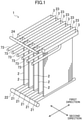
- FIG. 1 schematically illustrates an entire configuration of the vaporizer.
- the vaporizer is a so-called open rack vaporizer (ORV) 1.
- ORV 1 is placed on a floating body on water.
- the ORV 1 is, for example, mounted on a liquefied gas carrier.
- the ORV 1 exchanges heat between carried liquefied gas and seawater as a heat medium, thereby turning the liquefied gas into gaseous gas.
- the ORV 1 may be placed on a floating storage and regasification unit (FSRU) or a floating production storage and offloading (FPSO).
- FSRU floating storage and regasification unit
- FPSO floating production storage and offloading
- the ORV 1 includes a plurality of heat exchange panels 2.
- the heat exchange panels 2 includes five heat exchange panels. Note that the number of heat exchange panels 2 may be an optional number.
- each heat exchange panel 2 is configured such that a plurality of heat transfer pipes is arrayed in a first direction and adjacent ones of the heat transfer pipes are joined to each other.
- the five heat exchange panels 2 are arranged in a second direction perpendicular to the first direction.
- the first direction described herein corresponds to a direction in which the bow and stern of a ship on which the ORV 1 is mounted are connected to each other.
- the second direction corresponds to a direction in which the port and starboard sides of the ship are connected to each other.
- a lower header tank 21 is arranged below each heat exchange panel 2.
- the single lower header tank 21 is provided for the single heat exchange panel 2.
- the lower header tank 21 extends in the first direction.
- a lower end of each heat transfer pipe is connected to the lower header tank 21.
- the lower header tank 21 distributes liquefied gas into each heat transfer pipe.
- Ends of the lower header tanks 21 arranged in the second direction are connected to an inlet manifold 22 extending in the second direction.
- the inlet manifold 22 distributes liquefied gas into each lower header tank 21.
- Liquefied gas is supplied into each heat transfer pipe through the inlet manifold 22 and the lower header tanks 21, and is vaporized while flowing upward in the heat transfer pipes.
- An upper header tank 23 is arranged above each heat exchange panel 2.
- the single upper header tank 23 is provided for the single heat exchange panel 2.
- the upper header tank 23 extends in the first direction.
- An upper end of each heat transfer pipe is connected to the upper header tank 23.
- the upper header tank 23 collects gaseous gas from each heat transfer pipe.
- Ends of the upper header tanks 23 arranged in the second direction are connected to an outlet manifold 24 extending in the second direction.
- the outlet manifold 24 collects and sends out gas from each upper header tank 23.
- liquefied gas may be supplied into each heat transfer pipe through the upper header tanks 23 and may be vaporized while flowing downward in the heat transfer pipes.
- Troughs 3 are arranged on both sides of each heat exchange panel 2 in the second direction.
- the trough 3 stores seawater, and supplies the stored seawater to an outer surface of the heat exchange panel 2.
- the trough 3 extends in the first direction in the vicinity of an upper portion of the heat exchange panel 2.
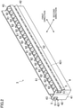
- FIG. 2 is a perspective view illustrating, as an example, an entire configuration of the trough 3.
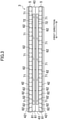
- FIG. 3 is a plan view of the trough 3
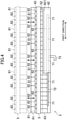
- FIG. 4 is a side view of the trough 3.
- FIG. 5 is a cutaway sectional view of the trough 3. Note that FIG. 5 illustrates two heat exchange panels 2 and illustrates three troughs 3 corresponding to these two heat exchange panels 2.
- the trough 3 at the left end of FIG. 5 is the trough 3 arranged on the leftmost side on the far side as viewed in FIG. 1 , and is the trough 3 at an end of the ORV 1.
- the trough 3 at the right end of FIG. 5 is the trough 3 arranged on the rightmost side on the near side as viewed in FIG. 1 , and is the trough 3 at an end of the ORV 1.
- the trough 3 arranged between adjacent ones of the heat exchange panels 2 has such a sectional shape that two troughs 3 arranged at the ends
- the trough 3 has a trough body 4 and a restriction plate 5 attached to the trough body 4.
- the trough body 4 has a bottom wall 41, two side walls 42, and two end walls 43. The trough body 4 opens upward.
- the bottom wall 41 extends in the first direction.
- the side walls 42 are connected to edges of the bottom wall 41 in the second direction. Each side wall 42 extends in the first direction.
- the two side walls 42 are arranged facing each other in the second direction.
- Each side wall 42 faces the heat exchange panel 2.
- the end walls 43 are connected to ends of the bottom wall 41 in the first direction.
- the side wall 42 connects the two opposing side walls 42 to each other.
- the height of the end wall 43 is higher than the height of the side wall 42.
- An edge portion 421 is provided at an upper end of the side wall 42.
- the edge portion 421 is formed in such a manner that an upper portion of the side wall 42 is folded back to the outside in the second direction.
- the edge portion 421 tilts diagonally downward.
- the edge portion 421 is continuous across the entirety of the side wall 42 extending in the first direction. Seawater in the trough 3 flows toward the heat exchange panel 2 along the edge portion 421.
- the restriction plate 5 is positioned above the side wall 42, and therefore, forms part of a side portion of the trough 3.
- the restriction plate 5 extends in the first direction. Both end portions of the restriction plate 5 in the first direction are bent. Both end portions of the restriction plate 5 are each fixed to the end walls 43.
- the restriction plate 5 is attached to the end walls 43 with bolts 51.
- the restriction plate 5 is detachable from the trough body 4.
- a clearance is provided between the restriction plate 5 and the side wall 42.
- a slit 52 extending in the first direction is formed at an intermediate position of the side wall of the trough 3 in a height direction thereof. More specifically, the slit 52 is positioned above a center position of the side wall of the trough 3 having an entire height from an upper end of the restriction plate 5 to a lower end of the side wall 42. Note that the height position of the slit 52 is not limited to that of the illustrated example and may be an optional position. Moreover, the slit 52 is continuous from an end to an end of the trough 3 in the first direction.
- bolt holes 53 for attachment of the restriction plate 5 are elongated in an upper-lower direction.
- the restriction plate 5 is configured so that the position of attachment to the trough body 4 can be changed in the upper-lower direction.
- the upper-lower width W1 of the slit 52 is narrowed.
- the upper-lower width W2 of the slit 52 is expanded.
- a partition wall 61 is arranged in the trough 3.
- the partition wall 61 extends in the first direction at a center position in the second direction.
- the partition wall 61 contacts the bottom wall 41.
- the height of the partition wall 61 is higher than the height of the end wall 43.
- the partition wall 61 divides the inside of the trough 3 into two spaces in the second direction.
- one side wall 42 is formed higher than the height of the end wall 43.
- the side wall 42 higher than the height of the end wall 43 performs a function similar to that of the partition wall 61.
- a plurality of partition plates 62 is arranged.
- the plurality of partition plates 62 is arranged at equal intervals in the first direction in each of the two spaces divided by the partition wall 61 in the trough 3.
- Each partition plate 62 contacts the bottom wall 41, the side walls 42, and the partition wall 61.
- An upper end of each partition plate 62 is positioned at the same position or the substantially same position as that of an upper end of the end wall 43.
- four partition plates 62 divide the inside of the trough 3 into five spaces in the first direction. Note that the number of divisions in the first direction by the partition plates 62 is not limited to five.
- the inside of the trough 3 may be divided into an optional number in the first direction.
- the inside of the trough 3 is not necessarily divided in the first direction.
- the partition plates 62 can be omitted.
- the trough 3 has supply ports 71 for supplying seawater into the trough 3.
- the supply ports 71 are each separately provided at the total of 10 spaces divided by the partition wall 61 and the partition plates 62. More specifically, the supply ports 71 are provided at a distribution pipe 72 arranged in the trough 3.
- the distribution pipe 72 includes a pipe closed at both ends.
- the distribution pipe 72 is arranged to extend in the first direction in each of the two spaces divided by the partition wall 61.
- the distribution pipe 72 penetrates the partition plates 62.
- the supply ports 71 provided at predetermined positions of the distribution pipe 72 are each positioned in the spaces divided in the first direction.
- the supply port 71 is formed at a lower portion of the distribution pipe 72, and opens downward.
- supply pipes 73 are each connected to the distribution pipe 72 (also see FIG. 1 ). Seawater supplied into the distribution pipe 72 through the supply pipes 73 is discharged into the trough 3 through the supply ports 71.
- a baffle plate 81 is interposed among the supply ports 71 and the side wall 42.
- the baffle plate 81 restricts the flow of seawater in the trough 3.
- the baffle plate 81 is arranged in parallel with the side wall 42 with a predetermined clearance from the side wall 42 in the second direction.
- a lower end of the baffle plate 81 is separated from the bottom wall 41 of the trough 3.
- the lower end of the baffle plate 81 is positioned lower than the slit 52.
- seawater flows around the baffle plate 81. More specifically, seawater flows from the supply ports 71 to a space between the side wall 42 and the baffle plate 81 through a position lower than the slit 52.
- Guide plates 82 are arranged in the space between the side wall 42 and the baffle plate 81.
- the guide plates 82 divide the space between the side wall 42 and the baffle plate 81 into a plurality of spaces in the first direction.
- four guide plates 82 are arranged at equal intervals in the first direction in each space divided by the partition plates 62. Such a space is divided into five spaces by the guide plates 82.
- the number of guide plates 82 is greater than the number of partition plates 62.
- Each guide plate 82 is fixed to the baffle plate 81, and is fixed to the restriction plate 5.
- the baffle plate 81 is fixed to the restriction plate 5 through the guide plates 82.
- a lower end of the guide plate 82 is, in the illustrated example, set to the same position as that of the lower end of the baffle plate 81.
- the guide plate 82 does not divide two adjacent spaces with respect to the guide plate 82 in the vicinity of the bottom wall 41 of the trough 3. Note that although not shown in the figure, the lower end of the guide plate 82 may contact the bottom wall 41 of the trough 3.
- seawater flows from the supply ports 71 to the space between the side wall 42 and the baffle plate 81 through the position lower than the slit 52 to flow around the baffle plate 81.
- the guide plates 82 distribute, in the space between the side wall 42 and the baffle plate 81, seawater equally or substantially equally to the spaces divided by the guide plates 82.
- An upper end of the guide plate 82 tilts diagonally to connect an upper end of the baffle plate 81 and the upper end of the restriction plate 5 to each other. Note that unlike the illustrated example, the upper end of the guide plate 82 may be formed horizontally straight.
- the restriction plate 5, the baffle plate 81, and the guide plates 82 are integrally fixed to each other.
- the stiffness of the restriction plate 5 and the baffle plate 81 elongated in the first direction is enhanced.
- the restriction plate 5 is detachably attached to the trough body 4.
- the restriction plate 5, the baffle plate 81, and the guide plates 82 can be detached from the trough body 4 (see chain lines in FIGS. 4 and 5 ).
- seawater stored in the trough 3 flows through the slit 52, but in some cases, the slit 52 is clogged with, e.g., trash or shells in seawater.
- the restriction plate 5, the baffle plate 81, and the guide plates 82 are detached from the trough body 4 so that an operator can easily remove the trash etc. accumulated in the slit 52.
- the configuration for detaching the restriction plate 5, the baffle plate 81, and the guide plates 82 improves maintenance performance of the trough 3.
- the trough 3 having the above-described configuration supplies seawater in the trough 3 to the outer surface of the heat exchange panel 2 through the slit 52 provided at the intermediate position of the side wall 42. As illustrated as an example in FIG. 5 , seawater flows toward the outer surface of the heat exchange panel 2 along the edge portion 421.
- the slit 52 extends with the same width in the first direction.
- the trough 3 can supply seawater equally or substantially equally across the entirety of the heat exchange panel 2 in the first direction.
- the ORV 1 tilts to the first direction when the ship swings in a pitching direction in response to influence of wind or wave, and tilts to the second direction when the ship swings in a rolling direction.
- the trough 3 tilts to the first direction in association with tilting of the ORV 1 to the first direction (see ⁇ in FIG. 7 )
- one end portion of the trough 3 in the first direction moves upward, and the other end portion moves downward.
- a typical trough is configured such that seawater overflows from an upper end of a side wall. For this reason, when the upper end of the side wall moves upward relative to a water surface in response to tilting of the trough 3 in the first direction, a height difference between the upper end of the side wall and the water surface decreases, and accordingly, no seawater overflows or seawater is less likely to overflow.
- the trough 3 having the above-described trough 3 supplies seawater to the outer surface of the heat exchange panel 2 through the slit 52 provided at the intermediate position of the side wall 42. Even when the trough 3 tilts to the first direction, if a water surface WL in the trough 3 is at a position higher than the slit 52 as indicated by chain double-dashed lines as an example in FIG. 7 , the amount of seawater corresponding to the upper-lower width of the slit 52 can be supplied to the heat exchange panel 2 across the entirety thereof in the first direction. A situation where no seawater is supplied to part of the ORV 1 can be avoided, and the ORV 1 can favorably vaporize liquefied gas.
- the ORV 1 mounted on the ship as described herein is, for example, operated while the ship is in harbor.
- the ship in harbor has a relatively-small swing angle in the pitching direction.
- the tilting angle ⁇ of the trough 3 in the first direction is about several degrees, for example.
- the trough 3 is divided into the plurality of spaces in the first direction by the partition plates 62. This suppresses the water surface from reaching a position lower than the slit 52 in each space divided by the partition plates 62 even in a case where the trough 3 tilts to the first direction.
- the trough 3 can supply seawater to the heat exchange panel 2 across the entirety thereof in the first direction.
- the plurality of guide plates 82 is provided between the side wall 42 and the baffle plate 81, and therefore, in a case where the trough 3 tilts to the first direction, the flow of seawater in the first direction in the space between the side wall 42 and the baffle plate 81 is blocked by the guide plates 82.
- the trough 3 can supply seawater equally or substantially equally across the entirety of the heat exchange panel 2 in the first direction.
- the baffle plate 81 restricts the flow of seawater in the trough 3, and therefore, seawater supplied into the trough 3 through the supply ports 71 can be distributed equally or substantially equally in the first direction in the trough 3.
- seawater flows equally or substantially equally to the heat exchange panel 2 in the first direction through the slit 52 not only in a case where the trough 3 is in the horizontal direction but also in a case where the trough 3 tilts.
- the guide plates 82 between the side wall 42 and the baffle plate 81 contribute not only to blocking of movement of seawater in a case where the trough 3 tilts in the first direction but also equal or substantially equal distribution of seawater, which flows around the baffle plate 81 to flow into the space between the side wall 42 and the baffle plate 81, in the first direction.
- the partition plates 62 dividing the trough 3 elongated in the first direction into the plurality of spaces in the first direction and the guide plates 82 further dividing the inside of the spaces divided by the partition plates 62 into the plurality of spaces are provided at the trough 3.
- the upper-lower width of the slit 52 When the upper-lower width of the slit 52 is expanded, such expansion can suppress the trash etc. in seawater from clogging the slit 52.
- the upper-lower width of the slit 52 is changed according to use environment of the ORV 1 so that the ORV 1 can be stably operated.
- seawater can be, as illustrated in FIG. 8 , supplied to the heat exchange panels 2 on both sides of the trough 3 when the ORV 1 tilts to the second direction.
- the rolling angle of the ship in harbor tends to be greater than the pitching angle.
- the trough 3 having the above-described configuration can continuously supply seawater to the heat exchange panels 2 on both sides of the trough 3 even when the ship rolls with a relatively-great angle.
- the troughs 3 positioned at the ends in the second direction can supply, by the high side walls 42, seawater to the heat exchange panels 2 at the sides of the troughs 3 when the ORV 1 tilts to the second direction.
- the high side wall 42 fulfills the same function as that of the partition wall 61.
- the configuration of the vaporizer 1 is not limited to the above-described configuration of the ORV 1.
- a configuration other than the above-described configuration in which the distribution pipe 72 is provided in the trough 3 may be employed as the mechanism for supplying seawater to each space divided by the partition wall 61 and/or the partition plates 62 in the trough 3.
- a supply pipe may be separately connected to each space in the trough 3.
- the number of guide plates 82 is not limited to that of the above-described configuration example.
- the number of guide plates 82 may be an optional number.
- the guide plates 82 may be omitted.
- the baffle plate 81 can be omitted.
- the slit 52 is not necessarily formed continuously from the end to the end of the trough 3 in the first direction.
- the slit may be divided into a plurality of slits in the first direction.
Landscapes
- Engineering & Computer Science (AREA)
- Mechanical Engineering (AREA)
- General Engineering & Computer Science (AREA)
- Physics & Mathematics (AREA)
- Thermal Sciences (AREA)
- Chemical & Material Sciences (AREA)
- Combustion & Propulsion (AREA)
- Ocean & Marine Engineering (AREA)
- Heat-Exchange Devices With Radiators And Conduit Assemblies (AREA)
- Filling Or Discharging Of Gas Storage Vessels (AREA)
Abstract
Description
- The technique disclosed herein relates to a vaporizer.
-
Patent Document 1 describes a liquefied gas vaporizer mounted on, e.g., a ship. This vaporizer is a so-called open rack vaporizer. The open rack vaporizer includes heat exchange panels and troughs. The heat exchange panel is configured such that a plurality of heat transfer pipes is arrayed in a first direction. The heat exchange panel vaporizes liquefied gas in each heat transfer pipe. The heat exchange panels are arranged next to each other in a second direction perpendicular to the first direction. The trough extends in the first direction between adjacent ones of the heat exchange panels. The trough supplies a heat medium to an outer surface of the heat exchange panel. The heat medium in the trough overflows from an opening of an upper end of the trough because a water surface of the heat medium reaches a position higher than an edge of the opening. - The vaporizer described in
Patent Document 1 is placed on a swinging location. The trough has, at the center thereof, a partition plate higher than the edge of the opening. With this configuration, even in a case where the vaporizer tilts to the second direction, the heat medium overflows from the opening, and therefore, the trough can supply the heat medium to the heat exchange panel. - PATENT DOCUMENT 1:
Japanese Patent No. 6053389 - The vaporizer described in
Patent Document 1 is also configured such that the inside of the trough is divided into a plurality of spaces in the first direction so that the heat medium can be supplied to the entirety of the heat exchange panel even in a case where the vaporizer tilts to the first direction, i.e., a longitudinal direction of the trough. - However, there are concerns that when the vaporizer described in
Patent Document 1 greatly tilts to the first direction, the heat medium is less likely to overflow or no heat medium overflows at end portions of the trough in the first direction. - The technique disclosed herein can supply a heat medium to a heat exchange panel from the entirety of a trough even in a case where a vaporizer tilts to a longitudinal direction thereof.
- The technique described herein relates to a vaporizer.
- The vaporizer includes
- a heat exchange panel including a plurality of heat transfer pipes arrayed in a first direction and configured to vaporize liquefied gas flowing in each heat transfer pipe, and
- a trough arranged adjacent to the heat exchange panel in a second direction perpendicular to the first direction and configured to supply a heat medium to an outer surface of the heat exchange panel.
- The trough extends in the first direction, and a slit extending in the first direction is formed at an intermediate position of a side wall, which faces the heat exchange panel, of the trough in a height direction.
- The heat medium accumulated in the trough flows to the outer surface of the heat exchange panel through the slit.
- According to the vaporizer having this configuration, the slit extending in the first direction is formed at the intermediate position of the side wall of the trough in the height direction. When a water surface in the trough is at a position higher than the slit, the heat medium accumulated in the trough flows to the outer surface of the heat exchange panel through the slit. The amount of heat medium to be supplied to the heat exchange panel corresponds to the upper-lower width of the slit. Note that the "intermediate position" is an optional position between an upper end and a lower end of the side wall and the slit may be provided at an optional height so that the heat medium can be stably supplied to the heat exchange panel.
- When the vaporizer tilts to the first direction, one end portion of the trough in the first direction moves upward, and the other end portion moves downward. At the end portion of the trough having moved upward, a height difference between the upper end of the side wall of the trough and the water surface decreases. However, this trough is not configured such that the heat medium overflows. This trough supplies the heat medium to the heat exchange panel through the slit formed at the intermediate position of the side wall in the height direction. In a case where the vaporizer tilts to the first direction, if the water surface in the trough is at a position higher than the slit, the heat medium flows to the outer surface of the heat exchange panel through the slit. At this point, the amount of heat medium to be supplied is an amount corresponding to the upper-lower width of the slit. Thus, even in a case where the vaporizer having the above-described configuration tilts to the first direction, the trough can supply the heat medium equally or substantially equally across the entirety of the heat exchange panel in the first direction.
- The trough may have a supply port for supplying the heat medium into the trough and a baffle plate arranged between the supply port and the side wall.
- The heat medium may flow from the supply port to the slit through a position lower than the slit to flow around the baffle plate.
- With this configuration, the heat medium supplied into the trough through the supply port flows, by due to the baffle plate, into a space between the side wall and the baffle plate through the position lower than the slit. While the heat medium is flowing around the baffle plate, the heat medium flows to expand in the first direction. The heat medium is distributed equally or substantially equally across the entirety of the inside of the trough in the first direction. Not only in a case where the vaporizer is in the horizontal direction, but also in a case where the vaporizer tilts to the first direction, the trough can supply the heat medium equally or substantially equally to the entirety of the heat exchange panel.
- The baffle plate may be arranged with a clearance from the side wall in the second direction, and may extend in the first direction.
- The trough may have a guide plate configured to divide the space between the side wall and the baffle plate into a plurality of spaces in the first direction.
- The guide plate described herein may completely divide two adjacent spaces with respect to the guide plate, or may divide these two spaces such that these two spaces are not completely separated from each other, but are partially connected to each other.
- The heat medium flowing into the space between the side wall and the baffle plate through the position lower than the slit is distributed equally or substantially equally to the plurality of spaces divided by the guide plate. The trough can supply the heat medium equally or substantially equally across the entirety of the heat exchange panel in the first direction.
- In a case where the vaporizer tilts to the first direction, the guide plate prevents the heat medium from flowing in the first direction in the trough. Even in a case where the vaporizer tilts to the first direction, the trough can supply the heat medium equally or substantially equally across the entirety of the heat exchange panel in the first direction.
- The trough may have a partition plate configured to divide a space in the trough into a plurality of spaces in the first direction.
- The partition plate described herein may completely divide two adjacent spaces with respect to the partition plate, thereby blocking the flow of heat medium in the first direction between the spaces sandwiching the partition plate. Alternatively, the partition plate does not completely divide two spaces from each other, but may divide two spaces such that these spaces are partially connected to each other.
- The trough is long in the first direction. In a case where the vaporizer tilts to the first direction, the partition plate prevents or suppresses the heat medium from flowing in the first direction in the trough. An uneven flow of heat medium to one side in the first direction in the trough is reduced. The trough divided into the plurality of spaces by the partition plate can supply the heat medium equally or substantially equally across the entirety of the heat exchange panel in the first direction.
- The number of guide plates may be greater than the number of partition plates.
- That is, the partition plate may divide the inside of the trough into the plurality of spaces, and the guide plate may further divide each of the plurality of spaces into a plurality of spaces. With both of the guide plate and the partition plate in the trough, even in a case where the vaporizer tilts to the first direction, the heat medium is supplied equally or substantially equally across the entirety of the heat exchange panel in the first direction.
- The trough may have a trough body and a restriction plate detachably attached to the trough body and forming part of the side wall.
- The slit may be formed between the trough body and the restriction plate.
- In a case where the heat medium is seawater, part of the slit might be clogged with, e.g., trash or shells in seawater. The restriction plate is detached from the trough body so that the trash etc. can be easily removed. Maintenance of the vaporizer is facilitated.
- The upper-lower width of the slit may be adjusted in such a manner that an attachment position of the restriction plate is changed.
- The upper-lower width of the slit is changed so that the amount of heat medium to be supplied from the trough to the heat exchange panel can be adjusted. In some cases, a great amount of trash etc. is contained in seawater as the heat medium. The upper-lower width of the slit is expanded according to use environment of the vaporizer so that clogging of the slit with the trash etc. can be reduced.
- The vaporizer may be placed on a floating body on water.
- As described above, the vaporizer can supply the heat medium from the entirety of the trough to the heat exchange panel even in a case where the vaporizer tilts to the longitudinal direction. Thus, the vaporizer is suitable as a vaporizer placed on a floating body (including a ship, a tied-up float, etc.) on water.
- As described above, the above-described vaporizer can supply the heat medium from the entirety of the trough to the heat exchange panel even in a case where the vaporizer tilts.
-
- [
FIG. 1] FIG. 1 is a perspective view schematically illustrating, as an example, an entire configuration of a vaporizer. - [
FIG. 2] FIG. 2 is a perspective view illustrating, as an example, the configuration of a trough. - [
FIG. 3] FIG. 3 is a plan view of the trough. - [
FIG. 4] FIG. 4 is a side view of the trough. - [
FIG. 5] FIG. 5 is a partial cutaway sectional view of the trough. - [
FIG. 6] FIG. 6 is a view illustrating, as an example, a restriction plate attachment structure. - [
FIG. 7] FIG. 7 is a side view illustrating, as an example, a state in which the vaporizer tilts to a first direction. - [
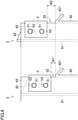
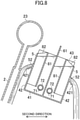
FIG. 8] FIG. 8 is a side view illustrating, as an example, a state in which the vaporizer tilts to a second direction. - Hereinafter, an embodiment of a vaporizer will be described with reference to the drawings. The vaporizer described herein is an example.
FIG. 1 schematically illustrates an entire configuration of the vaporizer. The vaporizer is a so-called open rack vaporizer (ORV) 1. TheORV 1 is placed on a floating body on water. TheORV 1 is, for example, mounted on a liquefied gas carrier. TheORV 1 exchanges heat between carried liquefied gas and seawater as a heat medium, thereby turning the liquefied gas into gaseous gas. TheORV 1 may be placed on a floating storage and regasification unit (FSRU) or a floating production storage and offloading (FPSO). - The
ORV 1 includes a plurality ofheat exchange panels 2. In the illustrated example, theheat exchange panels 2 includes five heat exchange panels. Note that the number ofheat exchange panels 2 may be an optional number. Although detailed illustration is omitted, eachheat exchange panel 2 is configured such that a plurality of heat transfer pipes is arrayed in a first direction and adjacent ones of the heat transfer pipes are joined to each other. The fiveheat exchange panels 2 are arranged in a second direction perpendicular to the first direction. The first direction described herein corresponds to a direction in which the bow and stern of a ship on which theORV 1 is mounted are connected to each other. The second direction corresponds to a direction in which the port and starboard sides of the ship are connected to each other. - A
lower header tank 21 is arranged below eachheat exchange panel 2. The singlelower header tank 21 is provided for the singleheat exchange panel 2. Thelower header tank 21 extends in the first direction. A lower end of each heat transfer pipe is connected to thelower header tank 21. Thelower header tank 21 distributes liquefied gas into each heat transfer pipe. Ends of thelower header tanks 21 arranged in the second direction are connected to aninlet manifold 22 extending in the second direction. Theinlet manifold 22 distributes liquefied gas into eachlower header tank 21. - Liquefied gas is supplied into each heat transfer pipe through the
inlet manifold 22 and thelower header tanks 21, and is vaporized while flowing upward in the heat transfer pipes. - An
upper header tank 23 is arranged above eachheat exchange panel 2. The singleupper header tank 23 is provided for the singleheat exchange panel 2. Theupper header tank 23 extends in the first direction. An upper end of each heat transfer pipe is connected to theupper header tank 23. Theupper header tank 23 collects gaseous gas from each heat transfer pipe. Ends of theupper header tanks 23 arranged in the second direction are connected to anoutlet manifold 24 extending in the second direction. Theoutlet manifold 24 collects and sends out gas from eachupper header tank 23. - Note that liquefied gas may be supplied into each heat transfer pipe through the
upper header tanks 23 and may be vaporized while flowing downward in the heat transfer pipes. -
Troughs 3 are arranged on both sides of eachheat exchange panel 2 in the second direction. Thetrough 3 stores seawater, and supplies the stored seawater to an outer surface of theheat exchange panel 2. Thetrough 3 extends in the first direction in the vicinity of an upper portion of theheat exchange panel 2. -
FIG. 2 is a perspective view illustrating, as an example, an entire configuration of thetrough 3.FIG. 3 is a plan view of thetrough 3, andFIG. 4 is a side view of thetrough 3.FIG. 5 is a cutaway sectional view of thetrough 3. Note thatFIG. 5 illustrates twoheat exchange panels 2 and illustrates threetroughs 3 corresponding to these twoheat exchange panels 2. Thetrough 3 at the left end ofFIG. 5 is thetrough 3 arranged on the leftmost side on the far side as viewed inFIG. 1 , and is thetrough 3 at an end of theORV 1. Thetrough 3 at the right end ofFIG. 5 is thetrough 3 arranged on the rightmost side on the near side as viewed inFIG. 1 , and is thetrough 3 at an end of theORV 1. Thetrough 3 arranged between adjacent ones of theheat exchange panels 2 has such a sectional shape that twotroughs 3 arranged at the ends are arranged back to back. - The
trough 3 has atrough body 4 and arestriction plate 5 attached to thetrough body 4. Thetrough body 4 has abottom wall 41, twoside walls 42, and twoend walls 43. Thetrough body 4 opens upward. - The
bottom wall 41 extends in the first direction. Theside walls 42 are connected to edges of thebottom wall 41 in the second direction. Eachside wall 42 extends in the first direction. The twoside walls 42 are arranged facing each other in the second direction. Eachside wall 42 faces theheat exchange panel 2. Theend walls 43 are connected to ends of thebottom wall 41 in the first direction. Theside wall 42 connects the two opposingside walls 42 to each other. The height of theend wall 43 is higher than the height of theside wall 42. - An
edge portion 421 is provided at an upper end of theside wall 42. Theedge portion 421 is formed in such a manner that an upper portion of theside wall 42 is folded back to the outside in the second direction. Theedge portion 421 tilts diagonally downward. Theedge portion 421 is continuous across the entirety of theside wall 42 extending in the first direction. Seawater in thetrough 3 flows toward theheat exchange panel 2 along theedge portion 421. - The
restriction plate 5 is positioned above theside wall 42, and therefore, forms part of a side portion of thetrough 3. Therestriction plate 5 extends in the first direction. Both end portions of therestriction plate 5 in the first direction are bent. Both end portions of therestriction plate 5 are each fixed to theend walls 43. Therestriction plate 5 is attached to theend walls 43 withbolts 51. Therestriction plate 5 is detachable from thetrough body 4. - A clearance is provided between the
restriction plate 5 and theside wall 42. With this configuration, aslit 52 extending in the first direction is formed at an intermediate position of the side wall of thetrough 3 in a height direction thereof. More specifically, theslit 52 is positioned above a center position of the side wall of thetrough 3 having an entire height from an upper end of therestriction plate 5 to a lower end of theside wall 42. Note that the height position of theslit 52 is not limited to that of the illustrated example and may be an optional position. Moreover, theslit 52 is continuous from an end to an end of thetrough 3 in the first direction. - As illustrated in
FIG. 6 , bolt holes 53 for attachment of therestriction plate 5 are elongated in an upper-lower direction. Therestriction plate 5 is configured so that the position of attachment to thetrough body 4 can be changed in the upper-lower direction. As illustrated on the left side inFIG. 6 , when therestriction plate 5 is attached to the lower side, the upper-lower width W1 of theslit 52 is narrowed. As illustrated on the right side inFIG. 6 , when therestriction plate 5 is attached to the upper side, the upper-lower width W2 of theslit 52 is expanded. - In the
trough 3, apartition wall 61 is arranged. Thepartition wall 61 extends in the first direction at a center position in the second direction. Thepartition wall 61 contacts thebottom wall 41. The height of thepartition wall 61 is higher than the height of theend wall 43. Thepartition wall 61 divides the inside of thetrough 3 into two spaces in the second direction. Although details will be described later, thepartition wall 61 allows stable supply of seawater to theheat exchange panels 2 on both sides of thetrough 3 in a case where thevaporizer 1 tilts to the second direction. - Note that as illustrated in
FIG. 5 , at thetroughs 3 arranged at the ends in the second direction, i.e., thetroughs 3 at the right and left ends as viewed inFIG. 5 , oneside wall 42 is formed higher than the height of theend wall 43. Theside wall 42 higher than the height of theend wall 43 performs a function similar to that of thepartition wall 61. - In the
trough 3, a plurality ofpartition plates 62 is arranged. The plurality ofpartition plates 62 is arranged at equal intervals in the first direction in each of the two spaces divided by thepartition wall 61 in thetrough 3. Eachpartition plate 62 contacts thebottom wall 41, theside walls 42, and thepartition wall 61. An upper end of eachpartition plate 62 is positioned at the same position or the substantially same position as that of an upper end of theend wall 43. In the illustrated example, in each of the two spaces divided by thepartition wall 61 in thetrough 3, fourpartition plates 62 divide the inside of thetrough 3 into five spaces in the first direction. Note that the number of divisions in the first direction by thepartition plates 62 is not limited to five. The inside of thetrough 3 may be divided into an optional number in the first direction. The inside of thetrough 3 is not necessarily divided in the first direction. Thepartition plates 62 can be omitted. - The
trough 3 hassupply ports 71 for supplying seawater into thetrough 3. Thesupply ports 71 are each separately provided at the total of 10 spaces divided by thepartition wall 61 and thepartition plates 62. More specifically, thesupply ports 71 are provided at adistribution pipe 72 arranged in thetrough 3. Thedistribution pipe 72 includes a pipe closed at both ends. Thedistribution pipe 72 is arranged to extend in the first direction in each of the two spaces divided by thepartition wall 61. Thedistribution pipe 72 penetrates thepartition plates 62. Thesupply ports 71 provided at predetermined positions of thedistribution pipe 72 are each positioned in the spaces divided in the first direction. Thesupply port 71 is formed at a lower portion of thedistribution pipe 72, and opens downward. - Although not illustrated in detail,
supply pipes 73 are each connected to the distribution pipe 72 (also seeFIG. 1 ). Seawater supplied into thedistribution pipe 72 through thesupply pipes 73 is discharged into thetrough 3 through thesupply ports 71. - A
baffle plate 81 is interposed among thesupply ports 71 and theside wall 42. Thebaffle plate 81 restricts the flow of seawater in thetrough 3. Specifically, thebaffle plate 81 is arranged in parallel with theside wall 42 with a predetermined clearance from theside wall 42 in the second direction. A lower end of thebaffle plate 81 is separated from thebottom wall 41 of thetrough 3. The lower end of thebaffle plate 81 is positioned lower than theslit 52. As indicated by an arrow inFIG. 5 , seawater flows around thebaffle plate 81. More specifically, seawater flows from thesupply ports 71 to a space between theside wall 42 and thebaffle plate 81 through a position lower than theslit 52. -
Guide plates 82 are arranged in the space between theside wall 42 and thebaffle plate 81. Theguide plates 82 divide the space between theside wall 42 and thebaffle plate 81 into a plurality of spaces in the first direction. In the illustrated example, fourguide plates 82 are arranged at equal intervals in the first direction in each space divided by thepartition plates 62. Such a space is divided into five spaces by theguide plates 82. The number ofguide plates 82 is greater than the number ofpartition plates 62. - Each
guide plate 82 is fixed to thebaffle plate 81, and is fixed to therestriction plate 5. Thebaffle plate 81 is fixed to therestriction plate 5 through theguide plates 82. - A lower end of the
guide plate 82 is, in the illustrated example, set to the same position as that of the lower end of thebaffle plate 81. Theguide plate 82 does not divide two adjacent spaces with respect to theguide plate 82 in the vicinity of thebottom wall 41 of thetrough 3. Note that although not shown in the figure, the lower end of theguide plate 82 may contact thebottom wall 41 of thetrough 3. - As described above, seawater flows from the
supply ports 71 to the space between theside wall 42 and thebaffle plate 81 through the position lower than theslit 52 to flow around thebaffle plate 81. Theguide plates 82 distribute, in the space between theside wall 42 and thebaffle plate 81, seawater equally or substantially equally to the spaces divided by theguide plates 82. - An upper end of the
guide plate 82 tilts diagonally to connect an upper end of thebaffle plate 81 and the upper end of therestriction plate 5 to each other. Note that unlike the illustrated example, the upper end of theguide plate 82 may be formed horizontally straight. - The
restriction plate 5, thebaffle plate 81, and theguide plates 82 are integrally fixed to each other. The stiffness of therestriction plate 5 and thebaffle plate 81 elongated in the first direction is enhanced. - The
restriction plate 5 is detachably attached to thetrough body 4. When therestriction plate 5 is detached from thetrough body 4, therestriction plate 5, thebaffle plate 81, and theguide plates 82 can be detached from the trough body 4 (see chain lines inFIGS. 4 and5 ). As described later, seawater stored in thetrough 3 flows through theslit 52, but in some cases, theslit 52 is clogged with, e.g., trash or shells in seawater. Therestriction plate 5, thebaffle plate 81, and theguide plates 82 are detached from thetrough body 4 so that an operator can easily remove the trash etc. accumulated in theslit 52. The configuration for detaching therestriction plate 5, thebaffle plate 81, and theguide plates 82 improves maintenance performance of thetrough 3. - The
trough 3 having the above-described configuration supplies seawater in thetrough 3 to the outer surface of theheat exchange panel 2 through theslit 52 provided at the intermediate position of theside wall 42. As illustrated as an example inFIG. 5 , seawater flows toward the outer surface of theheat exchange panel 2 along theedge portion 421. Theslit 52 extends with the same width in the first direction. Thetrough 3 can supply seawater equally or substantially equally across the entirety of theheat exchange panel 2 in the first direction. - Since the
ORV 1 is mounted on the ship in this configuration example, theORV 1 tilts to the first direction when the ship swings in a pitching direction in response to influence of wind or wave, and tilts to the second direction when the ship swings in a rolling direction. As illustrated as an example inFIG. 7 , when thetrough 3 tilts to the first direction in association with tilting of theORV 1 to the first direction (see θ inFIG. 7 ), one end portion of thetrough 3 in the first direction moves upward, and the other end portion moves downward. - A typical trough is configured such that seawater overflows from an upper end of a side wall. For this reason, when the upper end of the side wall moves upward relative to a water surface in response to tilting of the
trough 3 in the first direction, a height difference between the upper end of the side wall and the water surface decreases, and accordingly, no seawater overflows or seawater is less likely to overflow. - On the other hand, the
trough 3 having the above-describedtrough 3 supplies seawater to the outer surface of theheat exchange panel 2 through theslit 52 provided at the intermediate position of theside wall 42. Even when thetrough 3 tilts to the first direction, if a water surface WL in thetrough 3 is at a position higher than theslit 52 as indicated by chain double-dashed lines as an example inFIG. 7 , the amount of seawater corresponding to the upper-lower width of theslit 52 can be supplied to theheat exchange panel 2 across the entirety thereof in the first direction. A situation where no seawater is supplied to part of theORV 1 can be avoided, and theORV 1 can favorably vaporize liquefied gas. - The
ORV 1 mounted on the ship as described herein is, for example, operated while the ship is in harbor. The ship in harbor has a relatively-small swing angle in the pitching direction. The tilting angle θ of thetrough 3 in the first direction is about several degrees, for example. As described above, thetrough 3 is divided into the plurality of spaces in the first direction by thepartition plates 62. This suppresses the water surface from reaching a position lower than theslit 52 in each space divided by thepartition plates 62 even in a case where thetrough 3 tilts to the first direction. Thetrough 3 can supply seawater to theheat exchange panel 2 across the entirety thereof in the first direction. - The plurality of
guide plates 82 is provided between theside wall 42 and thebaffle plate 81, and therefore, in a case where thetrough 3 tilts to the first direction, the flow of seawater in the first direction in the space between theside wall 42 and thebaffle plate 81 is blocked by theguide plates 82. Thetrough 3 can supply seawater equally or substantially equally across the entirety of theheat exchange panel 2 in the first direction. - The
baffle plate 81 restricts the flow of seawater in thetrough 3, and therefore, seawater supplied into thetrough 3 through thesupply ports 71 can be distributed equally or substantially equally in the first direction in thetrough 3. As a result of reduction in an uneven flow of seawater in thetrough 3, seawater flows equally or substantially equally to theheat exchange panel 2 in the first direction through theslit 52 not only in a case where thetrough 3 is in the horizontal direction but also in a case where thetrough 3 tilts. - The
guide plates 82 between theside wall 42 and thebaffle plate 81 contribute not only to blocking of movement of seawater in a case where thetrough 3 tilts in the first direction but also equal or substantially equal distribution of seawater, which flows around thebaffle plate 81 to flow into the space between theside wall 42 and thebaffle plate 81, in the first direction. - The
partition plates 62 dividing thetrough 3 elongated in the first direction into the plurality of spaces in the first direction and theguide plates 82 further dividing the inside of the spaces divided by thepartition plates 62 into the plurality of spaces are provided at thetrough 3. With this configuration, not only a case where thetrough 3 is in the horizontal direction, but also in a case where thetrough 3 tilts, seawater can be supplied equally or substantially equally across the entirety of theheat exchange panel 2 in the first direction. - When the upper-lower width of the
slit 52 is changed in such a manner that the attachment position of therestriction plate 5 is changed, the amount of seawater to be supplied to theheat exchange panel 2 from thetrough 3 can be easily adjusted. - When the upper-lower width of the
slit 52 is expanded, such expansion can suppress the trash etc. in seawater from clogging theslit 52. The upper-lower width of theslit 52 is changed according to use environment of theORV 1 so that theORV 1 can be stably operated. - Since the
trough 3 is divided into the two spaces in the second direction by thehigh partition wall 61, seawater can be, as illustrated inFIG. 8 , supplied to theheat exchange panels 2 on both sides of thetrough 3 when theORV 1 tilts to the second direction. The rolling angle of the ship in harbor tends to be greater than the pitching angle. However, thetrough 3 having the above-described configuration can continuously supply seawater to theheat exchange panels 2 on both sides of thetrough 3 even when the ship rolls with a relatively-great angle. - Note that although not shown in the figure, the
troughs 3 positioned at the ends in the second direction can supply, by thehigh side walls 42, seawater to theheat exchange panels 2 at the sides of thetroughs 3 when theORV 1 tilts to the second direction. Thehigh side wall 42 fulfills the same function as that of thepartition wall 61. - Note that the configuration of the
vaporizer 1 is not limited to the above-described configuration of theORV 1. For example, a configuration other than the above-described configuration in which thedistribution pipe 72 is provided in thetrough 3 may be employed as the mechanism for supplying seawater to each space divided by thepartition wall 61 and/or thepartition plates 62 in thetrough 3. For example, a supply pipe may be separately connected to each space in thetrough 3. - The number of
guide plates 82 is not limited to that of the above-described configuration example. The number ofguide plates 82 may be an optional number. Theguide plates 82 may be omitted. - The
baffle plate 81 can be omitted. - The
slit 52 is not necessarily formed continuously from the end to the end of thetrough 3 in the first direction. The slit may be divided into a plurality of slits in the first direction. -
- 1
- ORV (Vaporizer)
- 2
- Heat Exchange Panel
- 3
- Trough
- 4
- Trough Body
- 42
- Side Wall
- 5
- Restriction Plate
- 52
- Slit
- 62
- Partition Plate
- 71
- Supply Port
- 81
- Baffle Plate
- 82
- Guide Plate
Claims (8)
- A vaporizer comprising:a heat exchange panel including a plurality of heat transfer pipes arrayed in a first direction and configured to vaporize liquefied gas flowing in each heat transfer pipe; anda trough arranged adjacent to the heat exchange panel in a second direction perpendicular to the first direction and configured to supply a heat medium to an outer surface of the heat exchange panel,wherein the trough extends in the first direction, and a slit extending in the first direction is formed at an intermediate position of a side wall, which faces the heat exchange panel, of the trough in a height direction, andthe heat medium accumulated in the trough flows to the outer surface of the heat exchange panel through the slit.
- The vaporizer according to claim 1, whereinthe trough has a supply port for supplying the heat medium into the trough and a baffle plate arranged between the supply port and the side wall, andthe heat medium flows from the supply port to the slit through a position lower than the slit to flow around the baffle plate.
- The vaporizer according to claim 2, whereinthe baffle plate is arranged with a clearance from the side wall in the second direction, and extends in the first direction, andthe trough has a guide plate configured to divide a space between the side wall and the baffle plate into a plurality of spaces in the first direction.
- The vaporizer according to any one of claims 1 to 3, wherein
the trough has a partition plate configured to divide a space in the trough into a plurality of spaces in the first direction. - The vaporizer according to claim 3, whereinthe trough has a partition plate configured to divide a space in the trough into a plurality of spaces in the first direction, andthe number of guide plates is greater than the number of partition plates.
- The vaporizer according to any one of claims 1 to 5, whereinthe trough has a trough body and a restriction plate detachably attached to the trough body and forming part of the side wall, andthe slit is formed between the trough body and the restriction plate.
- The vaporizer according to claim 6, wherein
an upper-lower width of the slit is adjusted in such a manner that an attachment position of the restriction plate is changed. - The vaporizer according to any one of claims 1 to 7, wherein
the vaporizer is placed on a floating body on water.
Applications Claiming Priority (2)
| Application Number | Priority Date | Filing Date | Title |
|---|---|---|---|
| JP2019092417A JP7495780B2 (en) | 2019-05-15 | 2019-05-15 | Vaporizer |
| PCT/JP2020/019413 WO2020230883A1 (en) | 2019-05-15 | 2020-05-15 | Vaporizer |
Publications (3)
| Publication Number | Publication Date |
|---|---|
| EP3964783A1 true EP3964783A1 (en) | 2022-03-09 |
| EP3964783A4 EP3964783A4 (en) | 2022-07-06 |
| EP3964783B1 EP3964783B1 (en) | 2023-08-02 |
Family
ID=73222370
Family Applications (1)
| Application Number | Title | Priority Date | Filing Date |
|---|---|---|---|
| EP20805415.5A Active EP3964783B1 (en) | 2019-05-15 | 2020-05-15 | Vaporizer |
Country Status (5)
| Country | Link |
|---|---|
| EP (1) | EP3964783B1 (en) |
| JP (1) | JP7495780B2 (en) |
| KR (1) | KR102601142B1 (en) |
| CN (1) | CN113811733B (en) |
| WO (1) | WO2020230883A1 (en) |
Family Cites Families (11)
| Publication number | Priority date | Publication date | Assignee | Title |
|---|---|---|---|---|
| JPS6053389B2 (en) | 1979-05-02 | 1985-11-25 | 日本コロムビア株式会社 | digital disk |
| JPS5824078Y2 (en) * | 1981-01-29 | 1983-05-23 | 東京瓦斯株式会社 | Water sprinkler for vaporization equipment |
| JPS6053389U (en) | 1983-09-16 | 1985-04-15 | 株式会社 日立工機原町工場 | Dust collector for woodworking |
| JPS6256990U (en) * | 1985-09-25 | 1987-04-08 | ||
| JPH067277Y2 (en) * | 1987-02-25 | 1994-02-23 | 東京瓦斯株式会社 | Sprinkling drift prevention device |
| JP3051655B2 (en) * | 1994-08-26 | 2000-06-12 | 有限会社甲斐田産業 | Raw seaweed trash removal equipment |
| JP6053389B2 (en) * | 2012-08-10 | 2016-12-27 | 三菱重工業株式会社 | Ship equipped with liquefied gas vaporizer and liquefied gas vaporizer |
| JP6118534B2 (en) * | 2012-10-30 | 2017-04-19 | 住友精密工業株式会社 | Open rack type vaporizer |
| JP6249842B2 (en) * | 2014-03-19 | 2017-12-20 | 住友精密工業株式会社 | Water film height measuring method and water film height measuring device of watering mechanism of open rack type vaporizer |
| JP6280775B2 (en) * | 2014-03-19 | 2018-02-14 | 住友精密工業株式会社 | Sprinkling mechanism of open rack type vaporizer |
| JP6769715B2 (en) * | 2016-02-26 | 2020-10-14 | 株式会社神戸製鋼所 | Sprinkler |
-
2019
- 2019-05-15 JP JP2019092417A patent/JP7495780B2/en active Active
-
2020
- 2020-05-15 EP EP20805415.5A patent/EP3964783B1/en active Active
- 2020-05-15 CN CN202080034740.0A patent/CN113811733B/en active Active
- 2020-05-15 WO PCT/JP2020/019413 patent/WO2020230883A1/en not_active Ceased
- 2020-05-15 KR KR1020217039546A patent/KR102601142B1/en active Active
Also Published As
| Publication number | Publication date |
|---|---|
| EP3964783A4 (en) | 2022-07-06 |
| JP7495780B2 (en) | 2024-06-05 |
| KR20220006563A (en) | 2022-01-17 |
| WO2020230883A1 (en) | 2020-11-19 |
| EP3964783B1 (en) | 2023-08-02 |
| JP2020186867A (en) | 2020-11-19 |
| KR102601142B1 (en) | 2023-11-10 |
| CN113811733B (en) | 2024-03-08 |
| CN113811733A (en) | 2021-12-17 |
Similar Documents
| Publication | Publication Date | Title |
|---|---|---|
| KR101594819B1 (en) | Falling liquid film heat exchanger, absorption refrigeration system, ship, offshore structure, and underwater structure | |
| JP6053389B2 (en) | Ship equipped with liquefied gas vaporizer and liquefied gas vaporizer | |
| JP2019151191A (en) | Vessel | |
| JP6118534B2 (en) | Open rack type vaporizer | |
| EP3964783B1 (en) | Vaporizer | |
| JP2017150784A (en) | Sprinkler system | |
| KR20160147870A (en) | Hull support structure for liquefied gas tank, and liquefied gas carrier vessel | |
| CN111409776B (en) | Rhombic isolation empty cabin structure of liquefied gas carrier | |
| KR101031266B1 (en) | Ballast system | |
| KR20100127470A (en) | Floating structure with multi-row arrangement of storage tank | |
| GB2128141A (en) | Tanker ship | |
| KR20160068088A (en) | Storage tank for lng management offshore facility and hold structure including the same | |
| EP3922938B1 (en) | Vaporization device | |
| KR102690371B1 (en) | Reinforced structure of ship | |
| KR101556199B1 (en) | Apparatus for liquefied gas vaporization | |
| CN113401285A (en) | Liquefied gas carrier | |
| CN111232147A (en) | Marine high-mounted anti-roll tank | |
| EP3922937A1 (en) | Vaporization device | |
| CN215891955U (en) | Trough for open rack type gasification device and open rack type gasification device | |
| JP7439355B2 (en) | Trough for open rack type vaporizer and open rack type vaporizer | |
| CN118560633A (en) | LNG-FSRU ship fuel tank arrangement modification method and fuel tank arrangement structure | |
| KR20250125254A (en) | Liquified Gas Carrier | |
| KR20200112690A (en) | Fence structure of ship | |
| CN104039643A (en) | Oil tank of tanker | |
| KR20110140022A (en) | Offshore Structure with Central Ballast Tank |
Legal Events
| Date | Code | Title | Description |
|---|---|---|---|
| STAA | Information on the status of an ep patent application or granted ep patent |
Free format text: STATUS: THE INTERNATIONAL PUBLICATION HAS BEEN MADE |
|
| PUAI | Public reference made under article 153(3) epc to a published international application that has entered the european phase |
Free format text: ORIGINAL CODE: 0009012 |
|
| STAA | Information on the status of an ep patent application or granted ep patent |
Free format text: STATUS: REQUEST FOR EXAMINATION WAS MADE |
|
| 17P | Request for examination filed |
Effective date: 20211130 |
|
| AK | Designated contracting states |
Kind code of ref document: A1 Designated state(s): AL AT BE BG CH CY CZ DE DK EE ES FI FR GB GR HR HU IE IS IT LI LT LU LV MC MK MT NL NO PL PT RO RS SE SI SK SM TR |
|
| A4 | Supplementary search report drawn up and despatched |
Effective date: 20220603 |
|
| RIC1 | Information provided on ipc code assigned before grant |
Ipc: F28F 25/04 20060101ALI20220530BHEP Ipc: F17C 9/02 20060101ALI20220530BHEP Ipc: F28D 3/02 20060101AFI20220530BHEP |
|
| DAV | Request for validation of the european patent (deleted) | ||
| DAX | Request for extension of the european patent (deleted) | ||
| GRAP | Despatch of communication of intention to grant a patent |
Free format text: ORIGINAL CODE: EPIDOSNIGR1 |
|
| STAA | Information on the status of an ep patent application or granted ep patent |
Free format text: STATUS: GRANT OF PATENT IS INTENDED |
|
| INTG | Intention to grant announced |
Effective date: 20230321 |
|
| GRAS | Grant fee paid |
Free format text: ORIGINAL CODE: EPIDOSNIGR3 |
|
| GRAA | (expected) grant |
Free format text: ORIGINAL CODE: 0009210 |
|
| STAA | Information on the status of an ep patent application or granted ep patent |
Free format text: STATUS: THE PATENT HAS BEEN GRANTED |
|
| AK | Designated contracting states |
Kind code of ref document: B1 Designated state(s): AL AT BE BG CH CY CZ DE DK EE ES FI FR GB GR HR HU IE IS IT LI LT LU LV MC MK MT NL NO PL PT RO RS SE SI SK SM TR |
|
| REG | Reference to a national code |
Ref country code: GB Ref legal event code: FG4D |
|
| REG | Reference to a national code |
Ref country code: CH Ref legal event code: EP |
|
| REG | Reference to a national code |
Ref country code: DE Ref legal event code: R096 Ref document number: 602020015141 Country of ref document: DE |
|
| REG | Reference to a national code |
Ref country code: IE Ref legal event code: FG4D |
|
| REG | Reference to a national code |
Ref country code: NO Ref legal event code: T2 Effective date: 20230802 |
|
| REG | Reference to a national code |
Ref country code: LT Ref legal event code: MG9D |
|
| REG | Reference to a national code |
Ref country code: NL Ref legal event code: MP Effective date: 20230802 |
|
| REG | Reference to a national code |
Ref country code: AT Ref legal event code: MK05 Ref document number: 1595223 Country of ref document: AT Kind code of ref document: T Effective date: 20230802 |
|
| PG25 | Lapsed in a contracting state [announced via postgrant information from national office to epo] |
Ref country code: GR Free format text: LAPSE BECAUSE OF FAILURE TO SUBMIT A TRANSLATION OF THE DESCRIPTION OR TO PAY THE FEE WITHIN THE PRESCRIBED TIME-LIMIT Effective date: 20231103 |
|
| PG25 | Lapsed in a contracting state [announced via postgrant information from national office to epo] |
Ref country code: IS Free format text: LAPSE BECAUSE OF FAILURE TO SUBMIT A TRANSLATION OF THE DESCRIPTION OR TO PAY THE FEE WITHIN THE PRESCRIBED TIME-LIMIT Effective date: 20231202 |
|
| PG25 | Lapsed in a contracting state [announced via postgrant information from national office to epo] |
Ref country code: SE Free format text: LAPSE BECAUSE OF FAILURE TO SUBMIT A TRANSLATION OF THE DESCRIPTION OR TO PAY THE FEE WITHIN THE PRESCRIBED TIME-LIMIT Effective date: 20230802 Ref country code: RS Free format text: LAPSE BECAUSE OF FAILURE TO SUBMIT A TRANSLATION OF THE DESCRIPTION OR TO PAY THE FEE WITHIN THE PRESCRIBED TIME-LIMIT Effective date: 20230802 Ref country code: PT Free format text: LAPSE BECAUSE OF FAILURE TO SUBMIT A TRANSLATION OF THE DESCRIPTION OR TO PAY THE FEE WITHIN THE PRESCRIBED TIME-LIMIT Effective date: 20231204 Ref country code: NL Free format text: LAPSE BECAUSE OF FAILURE TO SUBMIT A TRANSLATION OF THE DESCRIPTION OR TO PAY THE FEE WITHIN THE PRESCRIBED TIME-LIMIT Effective date: 20230802 Ref country code: LV Free format text: LAPSE BECAUSE OF FAILURE TO SUBMIT A TRANSLATION OF THE DESCRIPTION OR TO PAY THE FEE WITHIN THE PRESCRIBED TIME-LIMIT Effective date: 20230802 Ref country code: LT Free format text: LAPSE BECAUSE OF FAILURE TO SUBMIT A TRANSLATION OF THE DESCRIPTION OR TO PAY THE FEE WITHIN THE PRESCRIBED TIME-LIMIT Effective date: 20230802 Ref country code: IS Free format text: LAPSE BECAUSE OF FAILURE TO SUBMIT A TRANSLATION OF THE DESCRIPTION OR TO PAY THE FEE WITHIN THE PRESCRIBED TIME-LIMIT Effective date: 20231202 Ref country code: HR Free format text: LAPSE BECAUSE OF FAILURE TO SUBMIT A TRANSLATION OF THE DESCRIPTION OR TO PAY THE FEE WITHIN THE PRESCRIBED TIME-LIMIT Effective date: 20230802 Ref country code: GR Free format text: LAPSE BECAUSE OF FAILURE TO SUBMIT A TRANSLATION OF THE DESCRIPTION OR TO PAY THE FEE WITHIN THE PRESCRIBED TIME-LIMIT Effective date: 20231103 Ref country code: FI Free format text: LAPSE BECAUSE OF FAILURE TO SUBMIT A TRANSLATION OF THE DESCRIPTION OR TO PAY THE FEE WITHIN THE PRESCRIBED TIME-LIMIT Effective date: 20230802 Ref country code: AT Free format text: LAPSE BECAUSE OF FAILURE TO SUBMIT A TRANSLATION OF THE DESCRIPTION OR TO PAY THE FEE WITHIN THE PRESCRIBED TIME-LIMIT Effective date: 20230802 |
|
| PG25 | Lapsed in a contracting state [announced via postgrant information from national office to epo] |
Ref country code: PL Free format text: LAPSE BECAUSE OF FAILURE TO SUBMIT A TRANSLATION OF THE DESCRIPTION OR TO PAY THE FEE WITHIN THE PRESCRIBED TIME-LIMIT Effective date: 20230802 |
|
| PG25 | Lapsed in a contracting state [announced via postgrant information from national office to epo] |
Ref country code: ES Free format text: LAPSE BECAUSE OF FAILURE TO SUBMIT A TRANSLATION OF THE DESCRIPTION OR TO PAY THE FEE WITHIN THE PRESCRIBED TIME-LIMIT Effective date: 20230802 |
|
| PG25 | Lapsed in a contracting state [announced via postgrant information from national office to epo] |
Ref country code: SM Free format text: LAPSE BECAUSE OF FAILURE TO SUBMIT A TRANSLATION OF THE DESCRIPTION OR TO PAY THE FEE WITHIN THE PRESCRIBED TIME-LIMIT Effective date: 20230802 Ref country code: RO Free format text: LAPSE BECAUSE OF FAILURE TO SUBMIT A TRANSLATION OF THE DESCRIPTION OR TO PAY THE FEE WITHIN THE PRESCRIBED TIME-LIMIT Effective date: 20230802 Ref country code: ES Free format text: LAPSE BECAUSE OF FAILURE TO SUBMIT A TRANSLATION OF THE DESCRIPTION OR TO PAY THE FEE WITHIN THE PRESCRIBED TIME-LIMIT Effective date: 20230802 Ref country code: EE Free format text: LAPSE BECAUSE OF FAILURE TO SUBMIT A TRANSLATION OF THE DESCRIPTION OR TO PAY THE FEE WITHIN THE PRESCRIBED TIME-LIMIT Effective date: 20230802 Ref country code: DK Free format text: LAPSE BECAUSE OF FAILURE TO SUBMIT A TRANSLATION OF THE DESCRIPTION OR TO PAY THE FEE WITHIN THE PRESCRIBED TIME-LIMIT Effective date: 20230802 Ref country code: CZ Free format text: LAPSE BECAUSE OF FAILURE TO SUBMIT A TRANSLATION OF THE DESCRIPTION OR TO PAY THE FEE WITHIN THE PRESCRIBED TIME-LIMIT Effective date: 20230802 Ref country code: SK Free format text: LAPSE BECAUSE OF FAILURE TO SUBMIT A TRANSLATION OF THE DESCRIPTION OR TO PAY THE FEE WITHIN THE PRESCRIBED TIME-LIMIT Effective date: 20230802 |
|
| REG | Reference to a national code |
Ref country code: DE Ref legal event code: R097 Ref document number: 602020015141 Country of ref document: DE |
|
| PG25 | Lapsed in a contracting state [announced via postgrant information from national office to epo] |
Ref country code: IT Free format text: LAPSE BECAUSE OF FAILURE TO SUBMIT A TRANSLATION OF THE DESCRIPTION OR TO PAY THE FEE WITHIN THE PRESCRIBED TIME-LIMIT Effective date: 20230802 |
|
| PLBE | No opposition filed within time limit |
Free format text: ORIGINAL CODE: 0009261 |
|
| STAA | Information on the status of an ep patent application or granted ep patent |
Free format text: STATUS: NO OPPOSITION FILED WITHIN TIME LIMIT |
|
| 26N | No opposition filed |
Effective date: 20240503 |
|
| PG25 | Lapsed in a contracting state [announced via postgrant information from national office to epo] |
Ref country code: SI Free format text: LAPSE BECAUSE OF FAILURE TO SUBMIT A TRANSLATION OF THE DESCRIPTION OR TO PAY THE FEE WITHIN THE PRESCRIBED TIME-LIMIT Effective date: 20230802 |
|
| PG25 | Lapsed in a contracting state [announced via postgrant information from national office to epo] |
Ref country code: BG Free format text: LAPSE BECAUSE OF FAILURE TO SUBMIT A TRANSLATION OF THE DESCRIPTION OR TO PAY THE FEE WITHIN THE PRESCRIBED TIME-LIMIT Effective date: 20230802 |
|
| PG25 | Lapsed in a contracting state [announced via postgrant information from national office to epo] |
Ref country code: BG Free format text: LAPSE BECAUSE OF FAILURE TO SUBMIT A TRANSLATION OF THE DESCRIPTION OR TO PAY THE FEE WITHIN THE PRESCRIBED TIME-LIMIT Effective date: 20230802 |
|
| REG | Reference to a national code |
Ref country code: DE Ref legal event code: R119 Ref document number: 602020015141 Country of ref document: DE |
|
| REG | Reference to a national code |
Ref country code: CH Ref legal event code: PL |
|
| PG25 | Lapsed in a contracting state [announced via postgrant information from national office to epo] |
Ref country code: MC Free format text: LAPSE BECAUSE OF FAILURE TO SUBMIT A TRANSLATION OF THE DESCRIPTION OR TO PAY THE FEE WITHIN THE PRESCRIBED TIME-LIMIT Effective date: 20230802 |
|
| PG25 | Lapsed in a contracting state [announced via postgrant information from national office to epo] |
Ref country code: LU Free format text: LAPSE BECAUSE OF NON-PAYMENT OF DUE FEES Effective date: 20240515 |
|
| GBPC | Gb: european patent ceased through non-payment of renewal fee |
Effective date: 20240515 |
|
| PG25 | Lapsed in a contracting state [announced via postgrant information from national office to epo] |
Ref country code: MC Free format text: LAPSE BECAUSE OF FAILURE TO SUBMIT A TRANSLATION OF THE DESCRIPTION OR TO PAY THE FEE WITHIN THE PRESCRIBED TIME-LIMIT Effective date: 20230802 Ref country code: LU Free format text: LAPSE BECAUSE OF NON-PAYMENT OF DUE FEES Effective date: 20240515 Ref country code: CH Free format text: LAPSE BECAUSE OF NON-PAYMENT OF DUE FEES Effective date: 20240531 |
|
| REG | Reference to a national code |
Ref country code: BE Ref legal event code: MM Effective date: 20240531 |
|
| PG25 | Lapsed in a contracting state [announced via postgrant information from national office to epo] |
Ref country code: DE Free format text: LAPSE BECAUSE OF NON-PAYMENT OF DUE FEES Effective date: 20241203 |
|
| PG25 | Lapsed in a contracting state [announced via postgrant information from national office to epo] |
Ref country code: IE Free format text: LAPSE BECAUSE OF NON-PAYMENT OF DUE FEES Effective date: 20240515 |
|
| PG25 | Lapsed in a contracting state [announced via postgrant information from national office to epo] |
Ref country code: BE Free format text: LAPSE BECAUSE OF NON-PAYMENT OF DUE FEES Effective date: 20240531 |
|
| PG25 | Lapsed in a contracting state [announced via postgrant information from national office to epo] |
Ref country code: FR Free format text: LAPSE BECAUSE OF NON-PAYMENT OF DUE FEES Effective date: 20240531 |
|
| PG25 | Lapsed in a contracting state [announced via postgrant information from national office to epo] |
Ref country code: GB Free format text: LAPSE BECAUSE OF NON-PAYMENT OF DUE FEES Effective date: 20240515 |
|
| PGFP | Annual fee paid to national office [announced via postgrant information from national office to epo] |
Ref country code: NO Payment date: 20250523 Year of fee payment: 6 |
|
| PG25 | Lapsed in a contracting state [announced via postgrant information from national office to epo] |
Ref country code: CY Free format text: LAPSE BECAUSE OF FAILURE TO SUBMIT A TRANSLATION OF THE DESCRIPTION OR TO PAY THE FEE WITHIN THE PRESCRIBED TIME-LIMIT; INVALID AB INITIO Effective date: 20200515 |
|
| PG25 | Lapsed in a contracting state [announced via postgrant information from national office to epo] |
Ref country code: HU Free format text: LAPSE BECAUSE OF FAILURE TO SUBMIT A TRANSLATION OF THE DESCRIPTION OR TO PAY THE FEE WITHIN THE PRESCRIBED TIME-LIMIT; INVALID AB INITIO Effective date: 20200515 |